Download to read offline


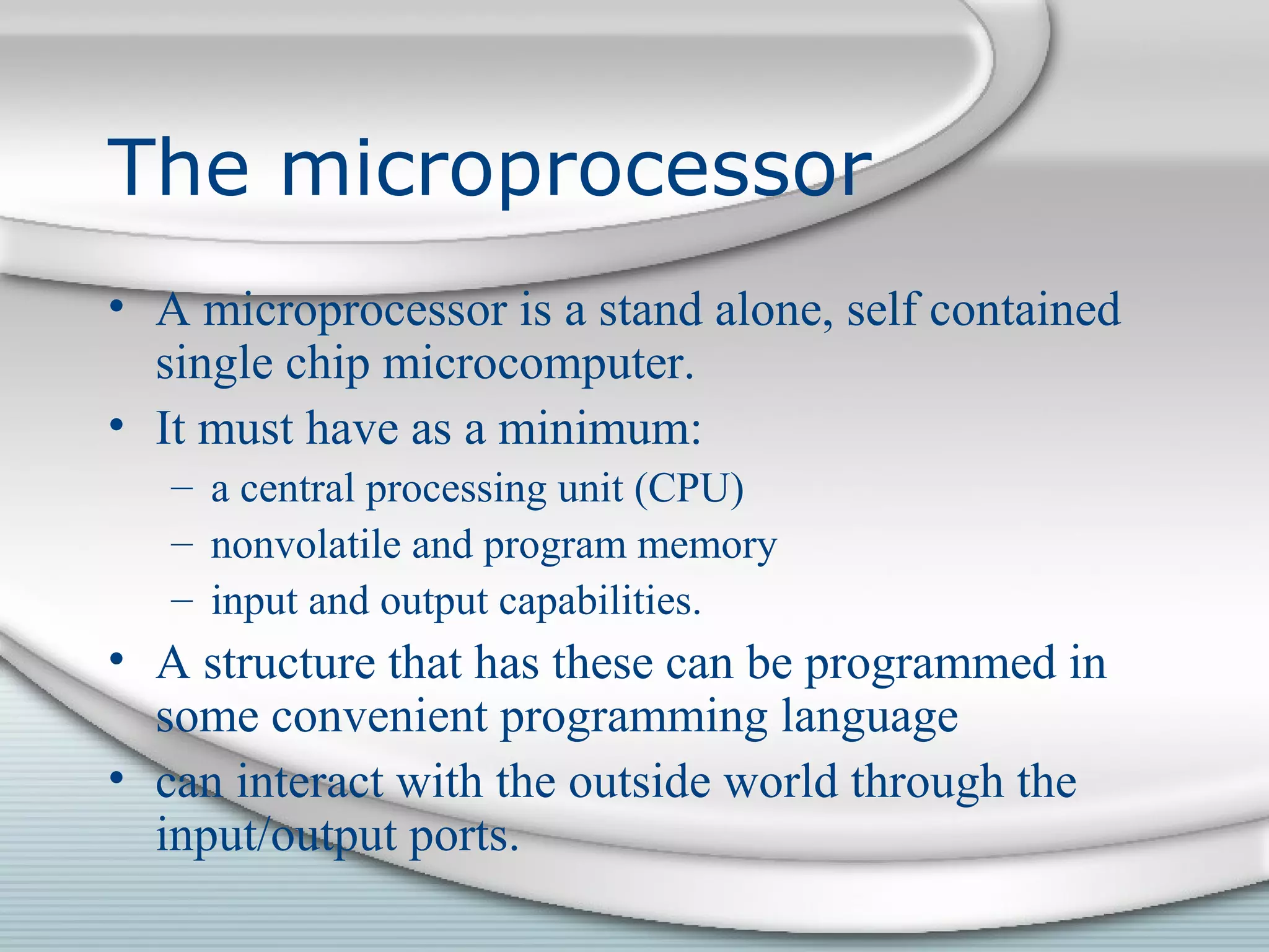


This document discusses interfacing microprocessors to sensors and actuators. It begins by defining what constitutes a controller and focuses on microprocessors. It describes the basic components and architecture of microprocessors, including the CPU, memory, I/O capabilities, addressing, and instruction sets. It discusses interfacing requirements such as signal levels, impedance matching, response times, and conditioning inputs. It also addresses interfacing outputs, power requirements, and programming microprocessors. Examples are provided to illustrate microprocessor components, capabilities, and interfacing challenges.