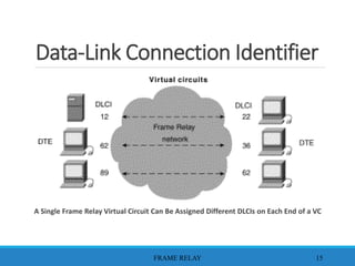
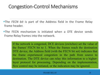
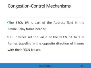
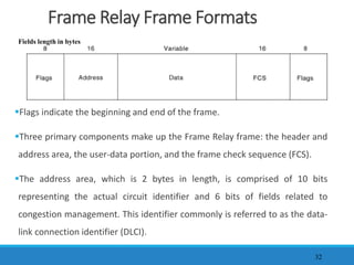
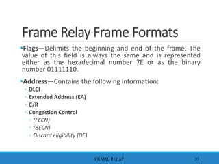
(ANJALI) Dange Chowk Call Girls Just Call 7001035870 [ Cash on Delivery ] Pun...
presentation detaillé parfaitement a propos du frameRelay
1. Lecture 7:
Data Link Layer Protocols (Part2):
Frame Relay
RISANURI HIDAYAT
FRAME RELAY 1
2. Frame Relay
Frame Relay is a high-performance WAN protocol
that operates at the physical and data link layers of
the OSI reference model.
Frame Relay originally was designed for use across
Integrated Services Digital Network (ISDN)
interfaces
FRAME RELAY 2
3. Packet Switching
Frame Relay is based on packet-switched
technology.
The following two techniques are used in
packet-switching technology:
◦ Variable-length packets
◦ Statistical multiplexing
FRAME RELAY 3
4. Frame Relay Devices
Devices attached to a Frame Relay WAN fall into the
following two general categories:
◦ Data terminal equipment (DTE)
◦ Data circuit-terminating equipment (DCE)
Examples of DTE devices are terminals, personal computers,
routers, and bridges.
FRAME RELAY 4
5. DCEs are carrier-owned internetworking devices.
The purpose of DCE equipment is to provide
clocking and switching services in a network, which
are the devices that actually transmit data through
the WAN.
In most cases, these are packet switches
FRAME RELAY 5
Packet Switching
7. Frame Relay Virtual Circuits
Frame Relay provides connection-oriented data link
layer communication.
This service is implemented by using a Frame Relay
virtual circuit, which is a logical connection created
between two data terminal equipment (DTE) devices
across a Frame Relay packet-switched network (PSN).
FRAME RELAY 7
8. Frame Relay Virtual Circuits
Virtual circuits provide a bidirectional communication path
from one DTE device to another and are uniquely identified
by a data-link connection identifier (DLCI).
A number of virtual circuits can be multiplexed into a single
physical circuit for transmission across the network.
FRAME RELAY 8
9. Frame Relay Virtual Circuits
A virtual circuit can pass through any number of
intermediate DCE devices (switches) located within the
Frame Relay Packet Switched Network (PSN).
Frame Relay virtual circuits fall into two categories:
1. Switched virtual circuits (SVCs)
2. Permanent virtual circuits (PVCs).
FRAME RELAY 9
10. Switched Virtual Circuits
Switched virtual circuits (SVCs) are temporary connections used in
situations requiring only interrupted data transfer between DTE
devices across the Frame Relay network.
◦ Call setup—VC between two Frame Relay DTE devices is established.
◦ Data transfer—Data is transmitted between the DTE devices over the VC.
◦ Idle—The connection between DTE devices is still active, but no data is transferred. If
an SVC remains in an idle state for a defined period of time, the call can be terminated.
◦ Call termination—The virtual circuit between DTE devices is terminated.
FRAME RELAY 10
11. Switched Virtual Circuits
Few manufacturers of Frame Relay DCE equipment support
switched virtual circuit connections. Therefore, their actual
deployment is minimal in today's Frame Relay networks.
Previously not widely supported by Frame Relay
equipment, SVCs are now the norm.
Companies have found that SVCs save money in the end
because the circuit is not open all the time
FRAME RELAY 11
12. Permanent Virtual Circuits
Permanent virtual circuits (PVCs) are permanently
established connections that are used for frequent and
consistent data transfers between DTE devices across the
Frame Relay network.
DTE devices can begin transferring data whenever they are
ready because the circuit is permanently established.
FRAME RELAY 12
13. Permanent Virtual Circuits
Communication across a PVC does not require
the call setup and termination states that are
used with SVCs.
◦ Data transfer—Data is transmitted between the DTE devices over the
virtual circuit.
◦ Idle—The connection between DTE devices is active, but no data is
transferred. Unlike SVCs, PVCs will not be terminated under any
circumstances when in an idle state.
FRAME RELAY 13
14. Data-Link Connection Identifier
Frame Relay virtual circuits are identified by data-link
connection identifiers (DLCIs).
DLCI values typically are assigned by the Frame Relay service
provider (for example, the telephone company).
Frame Relay DLCIs have local significance, which means that
their values are unique in the LAN, but not necessarily in the
Frame Relay WAN
FRAME RELAY 14
15. Data-Link Connection Identifier
A Single Frame Relay Virtual Circuit Can Be Assigned Different DLCIs on Each End of a VC
FRAME RELAY 15
16. Congestion-Control Mechanisms
Frame Relay reduces network overhead by implementing
simple congestion-notification mechanisms rather than
explicit, per-virtual-circuit flow control.
Frame Relay implements two congestion-notification
mechanisms:
1. Forward-explicit congestion notification (FECN)
2. Backward-explicit congestion notification (BECN)
FRAME RELAY 16
17. Congestion-Control Mechanisms
FECN and BECN each is controlled by a single bit
contained in the Frame Relay frame header.
The Frame Relay frame header also contains a
Discard Eligibility (DE) bit, which is used to identify
less important traffic that can be dropped during
periods of congestion.
FRAME RELAY 17
18. Congestion-Control Mechanisms
The FECN bit is part of the Address field in the Frame Relay
frame header.
The FECN mechanism is initiated when a DTE device sends
Frame Relay frames into the network.
FRAME RELAY 18
If the network is congested, DCE devices (switches) set the value of
the frames' FECN bit to 1. When the frames reach the destination
DTE device, the Address field (with the FECN bit set) indicates that
the frame experienced congestion in the path from source to
destination. The DTE device can relay this information to a higher-
layer protocol for processing. Depending on the implementation,
flow control may be initiated, or the indication may be ignored.
19. Congestion-Control Mechanisms
The BECN bit is part of the Address field in the
Frame Relay frame header.
DCE devices set the value of the BECN bit to 1 in
frames traveling in the opposite direction of frames
with their FECN bit set.
FRAME RELAY 19
20. This informs the receiving DTE device that a
particular path through the network is congested.
The DTE device then can relay this information to a
higher-layer protocol for processing.
Depending on the implementation, flow-control may
be initiated, or the indication may be ignored
FRAME RELAY 20
Congestion-Control Mechanisms
21. Frame Relay Discard Eligibility
The DE bit is part of the Address field in the Frame
Relay frame header.
The Discard Eligibility (DE) bit is used to indicate that
a frame has lower importance than other frames.
FRAME RELAY 21
22. Frame Relay Discard Eligibility
DTE devices can set the value of the DE bit of a
frame to 1 to indicate that the frame has lower
importance than other frames.
When the network becomes congested, DCE devices
will discard frames with the DE bit set.
FRAME RELAY 22
23. Frame Relay Error Checking
Frame Relay uses a common error-checking mechanism
known as the cyclic redundancy check (CRC).
The CRC compares two calculated values to determine
whether errors occurred during the transmission from source
to destination.
Frame Relay reduces network overhead by implementing
error checking rather than error correction.
FRAME RELAY 23
24. Frame Relay
Local Management Interface
The Local Management Interface (LMI) is a set of
enhancements to the basic Frame Relay specification
The LMI global addressing extension gives Frame Relay
(DLCI) values global rather than local significance.
DLCI values become DTE addresses that are unique in
the Frame Relay WAN.
FRAME RELAY 24
25. Frame Relay
Local Management Interface
LMI virtual circuit status messages provide
communication and synchronization between Frame
Relay DTE and DCE devices.
These messages are used to periodically report on
the status of PVCs.
FRAME RELAY 25
26. Frame Relay Network Implementation
A common private Frame Relay network
implementation is to equip a T1 multiplexer with
both Frame Relay and non-Frame Relay interfaces.
Frame Relay traffic is forwarded out the Frame Relay
interface and onto the data network.
FRAME RELAY 26
27. Frame Relay Network Implementation
Non-Frame Relay traffic is forwarded to the
appropriate application or service, such as a private
branch exchange (PBX) for telephone service or to a
video-teleconferencing application.
FRAME RELAY 27
29. Public Carrier-Provided Networks
In public carrier-provided Frame Relay networks, the
Frame Relay switching equipment is located in the
central offices of a telecommunications carrier.
Subscribers are charged based on their network use
but are relieved from administering and maintaining
the Frame Relay network equipment and service.
FRAME RELAY 29
30. Public Carrier-Provided Networks
DCE equipment either will be customer-owned or perhaps
will be owned by the telecommunications provider as a
service to the customer. Generally, the DCE equipment also is
owned by the telecommunications provider.
The majority of today's Frame Relay networks are public
carrier-provided networks.
FRAME RELAY 30
31. Private Enterprise Networks
More frequently, organizations worldwide are deploying
private Frame Relay networks.
In private Frame Relay networks, the administration and
maintenance of the network are the responsibilities of the
enterprise (a private company).
All the equipment, including the switching equipment, is
owned by the customer
FRAME RELAY 31
32. Frame Relay Frame Formats
Flags indicate the beginning and end of the frame.
Three primary components make up the Frame Relay frame: the header and
address area, the user-data portion, and the frame check sequence (FCS).
The address area, which is 2 bytes in length, is comprised of 10 bits
representing the actual circuit identifier and 6 bits of fields related to
congestion management. This identifier commonly is referred to as the data-
link connection identifier (DLCI).
32
Fields length in bytes
33. Frame Relay Frame Formats
Flags—Delimits the beginning and end of the frame. The
value of this field is always the same and is represented
either as the hexadecimal number 7E or as the binary
number 01111110.
Address—Contains the following information:
◦ DLCI
◦ Extended Address (EA)
◦ C/R
◦ Congestion Control
◦ (FECN)
◦ (BECN)
◦ Discard eligibility (DE)
FRAME RELAY 33
34. Frame Relay Frame Formats
DLCI—The 10-bit DLCI is the essence of the Frame Relay
header.
◦ This value represents the virtual connection between the DTE
device and the switch.
◦ Each virtual connection that is multiplexed onto the physical
channel will be represented by a unique DLCI.
◦ The DLCI values have local significance only, which means that
they are unique only to the physical channel on which they
reside.
FRAME RELAY 34
35. Frame Relay Frame Formats
Extended Address (EA)—The EA is used to indicate whether
the byte in which the EA value is 1 is the last addressing
field.
◦ If the value is 1, then the current byte is determined to be the
last DLCI octet.
◦ .The eighth bit of each byte of the Address field is used to
indicate the EA.
FRAME RELAY 35
36. Frame Relay Frame Formats
C/R—The C/R is the bit that follows the most significant
DLCI byte in the Address field. The C/R bit is not currently
defined.
Congestion Control—This consists of the 3 bits that control
the Frame Relay congestion-notification mechanisms.
◦ These are the FECN, BECN, and DE bits, which are the last 3
bits in the Address field.
FRAME RELAY 36
37. Frame Relay Frame Formats
Forward-explicit congestion notification (FECN)
◦ A single-bit field that can be set to a value of 1 by a switch to
indicate to an end DTE device, such as a router, that congestion
happened in the direction of the frame transmission from
source to destination.
◦ The primary benefit of the use of the FECN and BECN fields is
the capability of higher-layer protocols to react intelligently to
these congestion indicators.
FRAME RELAY 37
38. Frame Relay Frame Formats
• Backward-explicit congestion notification (BECN)
• Single-bit field that, when set to a value of 1 by a switch, indicates that
congestion happened in the network in the direction opposite of the
frame transmission from source to destination.
• Discard eligibility (DE)
• Set by the DTE device, such as a router, to indicate that the marked
frame is of lesser importance relative to other frames being
transmitted.
• Frames that are marked as "discard eligible" should be discarded before
other frames in a congested network.
FRAME RELAY 38
39. Frame Relay Frame Formats
Data—
◦ Contains encapsulated upper-layer data.
◦ Each frame in this variable-length field includes a user data or
payload field that will vary in length up to 16,000 octets.
◦ This field serves to transport the higher-layer protocol packet
(PDU) through a Frame Relay network.
Frame Check Sequence—
◦ Ensures the integrity of transmitted data.
◦ This value is computed by the source device.
◦ Verified by the receiver to ensure integrity of transmission.
FRAME RELAY 39