Download to read offline

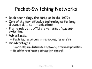
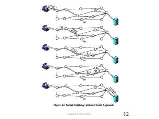
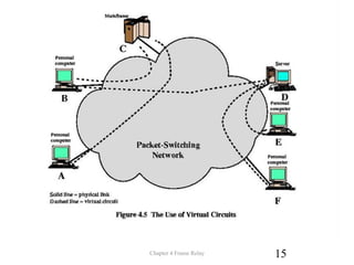
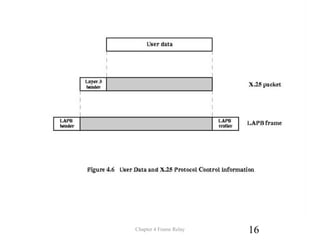
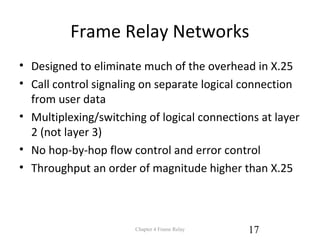
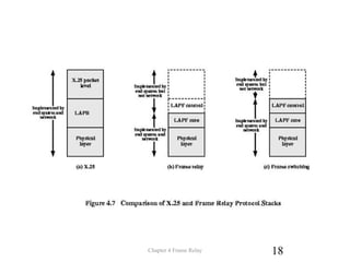
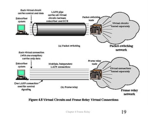

Frame Relay is a packet switching technology that was developed to improve on X.25 networks. It uses virtual circuits to transfer user data in frames more efficiently than X.25 by eliminating much of the overhead and removing hop-by-hop flow and error control. Frame Relay networks operate at the data link layer and use logical connections identified by a Data Link Connection Identifier to multiplex and switch user data frames, while call setup and teardown is handled on a separate control channel.