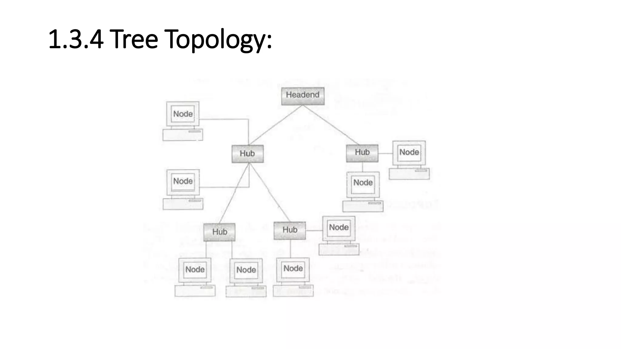
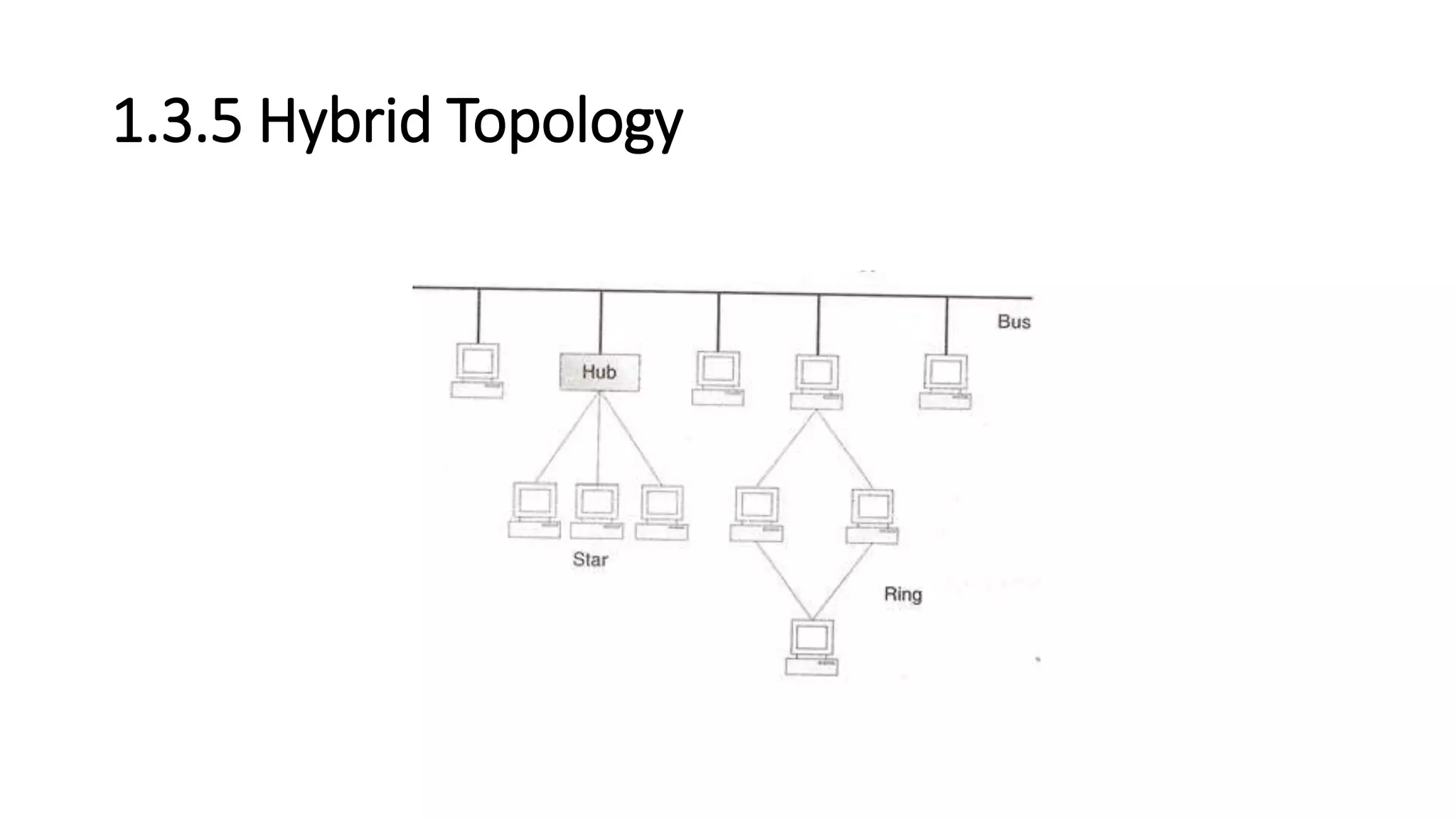
CHAPTER 1
INTRODUCTION TO COMPUTER NETWORKS
Objective :
• To understand networking concepts,
• connection oriented and connection less communication,
• network topologies, concept of LAN, MAN, WAN ,
• lastly and Analysis & comparison of OSI and TCP/IP reference model
for data communication.
1.1 Introduction
• Earlier, computer networks consisted of mainframes in an enclosure. Input was in the form of
punch cards read by card readers and output was in the form of printed results via local printers.
• Local terminals were mostly used for control and programming input.
• In parallel to the development of data networking, the computers began to change. Computers
became more powerful as processor speeds increased with the development of faster
microprocessors on silicon chips.
• Memory became more available as chip technology and hard drive technology improved.
• Additionally, computers became smaller and less expensive, to the point that the typical desktop
PC is equivalent to an early mainframe that would have filled a moderate-size office building.
• As a result, all of this computing power and storage capability on all of these desktops would lead
to a need to network those devices within the workplace.
• It has been estimated that majority of data transfer is confined to the workplace, while only small
percentage travels to remote places. Therefore, it is clear that PC users need to share access to
hosts, databases, printers, etc. LANs provide a solution to that requirement.
1.2 History (Development) of Computer
Networks
• Each of the past three centuries has been dominated by a single technology.
• The 18th century was the era of the great mechanical systems accompanying the
Industrial Revolution.
• The 19th century was the age' of the steam engine.
• During the 20th century, the key technology was information gathering,
processing, and distribution.
• Among other developments, we saw the installation of worldwide telephone
networks, the invention of radio and television, the birth and unprecedented
growth of the computer industry, and the launching of communication satellites.
• As a result of rapid technological progress, these areas are rapidly converging and
the differences between collecting, transporting, storing, and processing
information are quickly disappearing.
1.1.1 What is Network ?
• Network is defined as an interconnected collection of autonomous
computers.
• Two computers are said to be interconnected if they are capable of
exchanging information.
• Central to this definition is the fact that the computers are
autonomous.
• This means that no computer on the network can start, stop, or
control another.
1.3 Network Topologies
• Def: The pattern of interconnection of nodes in a network is called
the TOPOLOGY.
• The selection of a topology for a network cannot be done in isolation
as it affects the choice of media and the access method used. There
are a number of factors to consider in making this choice, the most
important of which are setout below:
• 1. Cost:
• 2. Flexibility
• 3. Reliability
1.3.1 The Star Topology
1.3.1 The Star Topology (cont..)
• This topology consists of a central node to which all other nodes are
connected by a single path.
• It is the topology used in most existing information networks
involving data processing or voice communications.
• The most common example of this is IBM 370 installations.
• In this case multiple 3270 terminals are connected to either a host
system or a terminal controller.
Advantages of the Star Topology
• 1. Ease of service: The star topology has a number of concentration points (where
connections are joined). These provide easy access for service or reconfiguration of the
network.
• 2. One device per connection: Connection points in any network are inherently prone to
failure in the star topology, failure of a single connection typically involves disconnecting
one node from an otherwise fully functional network.
• 3. Centralized control/problem diagnosis: The fact that the 'central node is connected
directly to every other node in the network means that faults are easily detected and
isolated. It is a simple matter to disconnect failing nodes from the system.
• 4. Simple access protocols: Any given connection in a star network involves only the
central node. In this situation, contention for who has control of the medium for the
transmission purposes is easily solved. Thus in a star network, access protocols are very
simple.
Disadvantages of the Star Topology.
• 1. Long cable length: Because each node is directly connected to the
center, the star topology necessitates a large quantity of cable as the
cost of cable is often small, congestion in cable ducts and
maintenance and installation problems can increase cost
considerably.
• 2. Difficult to expand: The addition of a new node to a star network
involves a connection all the way to the central node.
• 3. Central node dependency: If the central node in a star network
fails, the entire network is rendered inoperable. This introduces heavy
reliability and redundancy constraints on this node.
Examples of Star Topology
• Asynchronous Transmission Mode (ATM): ATM is the emerging
standard for communications.
• It can provide medium to high bandwidth and a virtual dedicated link
between ends for the delivery of real-time voice, data and video.
• Today, in most instances, separate networks are used to carry voice,
data and video information mostly because these traffic types have
different characteristics.
• For instance, data traffic tends to be "bursty". Bursty means that data
traffic does not need to communicate for an extended period of time
and whenever it needs, it communicates large quantities of
information as fast as possible
1.3.2 The Bus or Linear Topology
1.3.2 The Bus or Linear Topology(conti..)
• Another popular topology for data networks is the linear. This consists
of a single length of the transmission medium (normally coaxial cable)
onto which the various nodes are attached.
• The topology is used in traditional data communication network
where the host at one end of the bus communicates with several
terminals attached along its length.
• The transmission from any station travels the length of the bus, in
both directions, and can be received by another stations.
• The bus has terminators at either end which absorb the signal,
removing it from the bus.
• Data is transmitted in small blocks, known as packets.
• Each packet has some data bits, plus a header containing its
destination address.
• A station wanting to transmit some data sends it in packets along the
bus.
• The destination device, on identifying the address on the packets,
copies the data onto its disk.
Advantages of the Linear Topology
• 1. Short cable length and simple wiring layout: Because there is a
single common data path connecting all nodes, the linear topology
allows a very short cable length to be used.
• This decreases the installation cost, and also leads to a simple, easy to
maintain wiring layout.
• 2. Resilient Architecture: The LINEAR architecture has an inherent
simplicity that makes it very reliable from a hardware point of view.
• There is a single cable through which all the data propagates and to
which all nodes are connected.
• 3. Easy to extend: Additional nodes can be connected to an existing
bus network at any point along its length. More extensive additions
can be achieved by adding extra segments connected by a type of
signal amplifier known as repeater.
Disadvantages of the Bus (Linear) Topology
• 1. Fault diagnosis is difficult: Although simplicity of the bus topology means that
there is very little to go wrong, fault detection is not a simple matter.
• Control of the network is not centralized in any particular node. This means that
detection of a fault may have to .be performed from many points in the network.
• 2. Fault isolation is difficult: In the star topology, a defective node can easily be
isolated from the network by removing its connection at the center.
• If a node is faulty on the bus, it must be rectified at the point where the node is
connected to the network.
• 3. Repeater configuration: When BUS type network has its backbone extended
using repeaters, reconfiguration may be necessary.
• 4. Nodes must be intelligent: Each node on the network is directly connected to
the central bus.
• This means that some way of deciding who can use the network at any given
time must be performed in each node.
Examples of Bus Topology
• Ethernet: Ethernet is the least expensive high-speed LAN alternative.
It transmits and receives data at a speed of 10 million bits per second.
• Data is transferred between wiring closets using either a heavy coaxial
cable (thick net) or fiber optic cable. Thick net coaxial is still used for
medium-long distances where medium levels of reliability are
needed.
• Fiber goes farther and has greater reliability but a higher cost.
1.3.3 The Ring or Circular Topology
• The third topology that we will consider is the ring or circular. In this
case, each node is connected to two and only two neighboring nodes.
• Data is accepted from one of the neighboring nodes and is
transmitted onwards to another.
• Thus data travels in one direction only, from node to node around the
ring. After passing through each node, it returns to the sending node,
which removes it.
• It is important to note that data 'passed through' rather than 'travels
past‘ each node. This means that the signal may be amplified before
being 'repeated‘ on the out ward channel.
Advantages of the Ring Topology
• 1. Short cable length. The amount of cabling involved in a ring
topology is comparable to that of a bus and is small relative to that of
a star. This means that less connections will be needed, which will in
turn increase network reliability.
• 2. No wiring closet space required. Since there is only one cable
connecting each node to its immediate neighbors, it is not necessary
to allocate space in the building for wiring closets.
• 3. Suitable for optical fibers. Using optical fibers offers the possibility
of very high speed transmission. Because traffic on a ring travels in
one direction, it is easy to use optical fibers as a medium of
transmission.
Disadvantages of the Ring Topology
• 1. Node failure causes network failure. The transmission of data on a ring
goes through every connected node on the ring before returning to the
sender.
• If one node fails to pass data through itself, the entire network has failed
and. No traffic can flow until the defective node has been removed from
the ring.
• 2. Difficult to diagnose faults. The fact that failure of one node will affect
all others has serious implications for fault diagnosis.
• It may be necessary to examine a series of adjacent nodes to determine
the faulty one. This operation may also require diagnostic facilities to be
built into each node.
• 3. Network reconfiguration is difficult. It is not possible to shut down a
small section of the ring while keeping the majority of it working normally.
1.3.4 Tree Topology:
1.3.4 Tree Topology (conti..)
• The central hub contains a repeater, which looks at the incoming bits
and regenerates them afresh as the full blown signals for 0 or 1 as
required.
• This allows the digital signals to traverse over longer distances.
Therefore, the central hub is also called active hubs. The tree
topology also contains many secondary hubs, which may be active
hubs or passive hubs.
• The merits and demerits of tree topology are almost similar to those
of the star topology
1.3.5 Hybrid Topology
• Hybrid topology is one that uses two or more of the topologies
mentioned above together,
• In this case, the bus, star and ring topologies are used to create this
hybrid topology.
• There are multiple ways in which this can be created.
• In practice, many networks are quite complex but they can be
reduced to some form of hybrid topology.
1.6 The OSI Reference Model
• The OSI model is based on a proposal developed by the International
Standards Organization (ISO) as a first step toward international
standardization of the protocols used in the various layers.
• The model is called the ISO OSI (Open Systems Interconnection)
Reference Model because it deals with connecting open systems-that
is, systems that are open for communication with other systems
The OSI Reference Model
• The OSI model has seven layers. The principles that were applied to
arrive at the seven layers can be briefly summarized as follows:
• 1. A layer should be created where a different abstraction is needed.
• 2. Each layer should perform a well-defined function.
• 3. The function of each layer should be chosen with an eye toward defining
internationally standardized protocols.
• 4. The layer boundaries should be chosen to minimize the information flow
across the interfaces.
• 5. The number of layers should be large enough that distinct functions
need not be thrown together in the same layer out of necessity and small
enough that the architecture does not become unwieldy.
The Physical Layer:
• The physical layer is concerned with transmitting raw bits over a
communication channel.
• The design issues have to do with making sure that when one side
sends a 1 bit, it is received by the other side as a 1 bit, not as a 0 bit.
• The design issues here largely deal with mechanical, electrical, and
timing interfaces.
The physical layer has to take into account the
following factors:
• Signal encoding : How are the bits 0 and 1 to be represented ?
• Medium: What is the medium used, and what are its properties ?
• Bit synchronization: Is the transmission asynchronous or synchronous?
• Transmission type: Is the transmission serial or parallel ?
• Transmission mode : Is the transmission simplex, half-duplex or full
duplex ?
• Topology: What is the topology (mesh, star ring, bus or hybrid) used?
• Multiplexing: Is multiplexing used, and if so, what is its type (FDM, TDM)?
• Interface: How are the two closely linked devices connected ?
• Bandwidth: Which of the two baseband or broadband communication is
being used?
• Signal type: Are analog signals or digital ?
The Data Link Layer:
• The main task of the data link layer is to transform a raw transmission
facility into a line that appears free of undetected transmission errors
to the network layer.
• It accomplishes this task by having the sender break up the input
data into data frames.
• If the service is reliable, the receiver confirms correct receipt of each
frame by sending back an acknowledgement frame.
• issue that arises in the data link layer:
• how to keep a fast transmitter from drowning a slow receiver in data?
Broadcast networks have an additional issue
in the data link layer:
• How to control access to the shared channel?
• A special sublayer of the data link layer, the medium access control
sublayer, deals with this problem.

Chapter 1 ppt by dmb

  • 1.
    CHAPTER 1 INTRODUCTION TOCOMPUTER NETWORKS
  • 2.
    Objective : • Tounderstand networking concepts, • connection oriented and connection less communication, • network topologies, concept of LAN, MAN, WAN , • lastly and Analysis & comparison of OSI and TCP/IP reference model for data communication.
  • 3.
    1.1 Introduction • Earlier,computer networks consisted of mainframes in an enclosure. Input was in the form of punch cards read by card readers and output was in the form of printed results via local printers. • Local terminals were mostly used for control and programming input. • In parallel to the development of data networking, the computers began to change. Computers became more powerful as processor speeds increased with the development of faster microprocessors on silicon chips. • Memory became more available as chip technology and hard drive technology improved. • Additionally, computers became smaller and less expensive, to the point that the typical desktop PC is equivalent to an early mainframe that would have filled a moderate-size office building. • As a result, all of this computing power and storage capability on all of these desktops would lead to a need to network those devices within the workplace. • It has been estimated that majority of data transfer is confined to the workplace, while only small percentage travels to remote places. Therefore, it is clear that PC users need to share access to hosts, databases, printers, etc. LANs provide a solution to that requirement.
  • 4.
    1.2 History (Development)of Computer Networks • Each of the past three centuries has been dominated by a single technology. • The 18th century was the era of the great mechanical systems accompanying the Industrial Revolution. • The 19th century was the age' of the steam engine. • During the 20th century, the key technology was information gathering, processing, and distribution. • Among other developments, we saw the installation of worldwide telephone networks, the invention of radio and television, the birth and unprecedented growth of the computer industry, and the launching of communication satellites. • As a result of rapid technological progress, these areas are rapidly converging and the differences between collecting, transporting, storing, and processing information are quickly disappearing.
  • 5.
    1.1.1 What isNetwork ? • Network is defined as an interconnected collection of autonomous computers. • Two computers are said to be interconnected if they are capable of exchanging information. • Central to this definition is the fact that the computers are autonomous. • This means that no computer on the network can start, stop, or control another.
  • 6.
    1.3 Network Topologies •Def: The pattern of interconnection of nodes in a network is called the TOPOLOGY. • The selection of a topology for a network cannot be done in isolation as it affects the choice of media and the access method used. There are a number of factors to consider in making this choice, the most important of which are setout below: • 1. Cost: • 2. Flexibility • 3. Reliability
  • 7.
  • 8.
    1.3.1 The StarTopology (cont..) • This topology consists of a central node to which all other nodes are connected by a single path. • It is the topology used in most existing information networks involving data processing or voice communications. • The most common example of this is IBM 370 installations. • In this case multiple 3270 terminals are connected to either a host system or a terminal controller.
  • 9.
    Advantages of theStar Topology • 1. Ease of service: The star topology has a number of concentration points (where connections are joined). These provide easy access for service or reconfiguration of the network. • 2. One device per connection: Connection points in any network are inherently prone to failure in the star topology, failure of a single connection typically involves disconnecting one node from an otherwise fully functional network. • 3. Centralized control/problem diagnosis: The fact that the 'central node is connected directly to every other node in the network means that faults are easily detected and isolated. It is a simple matter to disconnect failing nodes from the system. • 4. Simple access protocols: Any given connection in a star network involves only the central node. In this situation, contention for who has control of the medium for the transmission purposes is easily solved. Thus in a star network, access protocols are very simple.
  • 10.
    Disadvantages of theStar Topology. • 1. Long cable length: Because each node is directly connected to the center, the star topology necessitates a large quantity of cable as the cost of cable is often small, congestion in cable ducts and maintenance and installation problems can increase cost considerably. • 2. Difficult to expand: The addition of a new node to a star network involves a connection all the way to the central node. • 3. Central node dependency: If the central node in a star network fails, the entire network is rendered inoperable. This introduces heavy reliability and redundancy constraints on this node.
  • 11.
    Examples of StarTopology • Asynchronous Transmission Mode (ATM): ATM is the emerging standard for communications. • It can provide medium to high bandwidth and a virtual dedicated link between ends for the delivery of real-time voice, data and video. • Today, in most instances, separate networks are used to carry voice, data and video information mostly because these traffic types have different characteristics. • For instance, data traffic tends to be "bursty". Bursty means that data traffic does not need to communicate for an extended period of time and whenever it needs, it communicates large quantities of information as fast as possible
  • 12.
    1.3.2 The Busor Linear Topology
  • 13.
    1.3.2 The Busor Linear Topology(conti..) • Another popular topology for data networks is the linear. This consists of a single length of the transmission medium (normally coaxial cable) onto which the various nodes are attached. • The topology is used in traditional data communication network where the host at one end of the bus communicates with several terminals attached along its length. • The transmission from any station travels the length of the bus, in both directions, and can be received by another stations. • The bus has terminators at either end which absorb the signal, removing it from the bus.
  • 14.
    • Data istransmitted in small blocks, known as packets. • Each packet has some data bits, plus a header containing its destination address. • A station wanting to transmit some data sends it in packets along the bus. • The destination device, on identifying the address on the packets, copies the data onto its disk.
  • 15.
    Advantages of theLinear Topology • 1. Short cable length and simple wiring layout: Because there is a single common data path connecting all nodes, the linear topology allows a very short cable length to be used. • This decreases the installation cost, and also leads to a simple, easy to maintain wiring layout. • 2. Resilient Architecture: The LINEAR architecture has an inherent simplicity that makes it very reliable from a hardware point of view. • There is a single cable through which all the data propagates and to which all nodes are connected. • 3. Easy to extend: Additional nodes can be connected to an existing bus network at any point along its length. More extensive additions can be achieved by adding extra segments connected by a type of signal amplifier known as repeater.
  • 16.
    Disadvantages of theBus (Linear) Topology • 1. Fault diagnosis is difficult: Although simplicity of the bus topology means that there is very little to go wrong, fault detection is not a simple matter. • Control of the network is not centralized in any particular node. This means that detection of a fault may have to .be performed from many points in the network. • 2. Fault isolation is difficult: In the star topology, a defective node can easily be isolated from the network by removing its connection at the center. • If a node is faulty on the bus, it must be rectified at the point where the node is connected to the network. • 3. Repeater configuration: When BUS type network has its backbone extended using repeaters, reconfiguration may be necessary. • 4. Nodes must be intelligent: Each node on the network is directly connected to the central bus. • This means that some way of deciding who can use the network at any given time must be performed in each node.
  • 17.
    Examples of BusTopology • Ethernet: Ethernet is the least expensive high-speed LAN alternative. It transmits and receives data at a speed of 10 million bits per second. • Data is transferred between wiring closets using either a heavy coaxial cable (thick net) or fiber optic cable. Thick net coaxial is still used for medium-long distances where medium levels of reliability are needed. • Fiber goes farther and has greater reliability but a higher cost.
  • 18.
    1.3.3 The Ringor Circular Topology
  • 19.
    1.3.3 The Ringor Circular Topology • The third topology that we will consider is the ring or circular. In this case, each node is connected to two and only two neighboring nodes. • Data is accepted from one of the neighboring nodes and is transmitted onwards to another. • Thus data travels in one direction only, from node to node around the ring. After passing through each node, it returns to the sending node, which removes it. • It is important to note that data 'passed through' rather than 'travels past‘ each node. This means that the signal may be amplified before being 'repeated‘ on the out ward channel.
  • 20.
    Advantages of theRing Topology • 1. Short cable length. The amount of cabling involved in a ring topology is comparable to that of a bus and is small relative to that of a star. This means that less connections will be needed, which will in turn increase network reliability. • 2. No wiring closet space required. Since there is only one cable connecting each node to its immediate neighbors, it is not necessary to allocate space in the building for wiring closets. • 3. Suitable for optical fibers. Using optical fibers offers the possibility of very high speed transmission. Because traffic on a ring travels in one direction, it is easy to use optical fibers as a medium of transmission.
  • 21.
    Disadvantages of theRing Topology • 1. Node failure causes network failure. The transmission of data on a ring goes through every connected node on the ring before returning to the sender. • If one node fails to pass data through itself, the entire network has failed and. No traffic can flow until the defective node has been removed from the ring. • 2. Difficult to diagnose faults. The fact that failure of one node will affect all others has serious implications for fault diagnosis. • It may be necessary to examine a series of adjacent nodes to determine the faulty one. This operation may also require diagnostic facilities to be built into each node. • 3. Network reconfiguration is difficult. It is not possible to shut down a small section of the ring while keeping the majority of it working normally.
  • 22.
  • 23.
    1.3.4 Tree Topology(conti..) • The central hub contains a repeater, which looks at the incoming bits and regenerates them afresh as the full blown signals for 0 or 1 as required. • This allows the digital signals to traverse over longer distances. Therefore, the central hub is also called active hubs. The tree topology also contains many secondary hubs, which may be active hubs or passive hubs. • The merits and demerits of tree topology are almost similar to those of the star topology
  • 24.
  • 25.
    1.3.5 Hybrid Topology •Hybrid topology is one that uses two or more of the topologies mentioned above together, • In this case, the bus, star and ring topologies are used to create this hybrid topology. • There are multiple ways in which this can be created. • In practice, many networks are quite complex but they can be reduced to some form of hybrid topology.
  • 26.
    1.6 The OSIReference Model • The OSI model is based on a proposal developed by the International Standards Organization (ISO) as a first step toward international standardization of the protocols used in the various layers. • The model is called the ISO OSI (Open Systems Interconnection) Reference Model because it deals with connecting open systems-that is, systems that are open for communication with other systems
  • 27.
    The OSI ReferenceModel • The OSI model has seven layers. The principles that were applied to arrive at the seven layers can be briefly summarized as follows: • 1. A layer should be created where a different abstraction is needed. • 2. Each layer should perform a well-defined function. • 3. The function of each layer should be chosen with an eye toward defining internationally standardized protocols. • 4. The layer boundaries should be chosen to minimize the information flow across the interfaces. • 5. The number of layers should be large enough that distinct functions need not be thrown together in the same layer out of necessity and small enough that the architecture does not become unwieldy.
  • 28.
    The Physical Layer: •The physical layer is concerned with transmitting raw bits over a communication channel. • The design issues have to do with making sure that when one side sends a 1 bit, it is received by the other side as a 1 bit, not as a 0 bit. • The design issues here largely deal with mechanical, electrical, and timing interfaces.
  • 29.
    The physical layerhas to take into account the following factors: • Signal encoding : How are the bits 0 and 1 to be represented ? • Medium: What is the medium used, and what are its properties ? • Bit synchronization: Is the transmission asynchronous or synchronous? • Transmission type: Is the transmission serial or parallel ? • Transmission mode : Is the transmission simplex, half-duplex or full duplex ? • Topology: What is the topology (mesh, star ring, bus or hybrid) used? • Multiplexing: Is multiplexing used, and if so, what is its type (FDM, TDM)? • Interface: How are the two closely linked devices connected ? • Bandwidth: Which of the two baseband or broadband communication is being used? • Signal type: Are analog signals or digital ?
  • 30.
    The Data LinkLayer: • The main task of the data link layer is to transform a raw transmission facility into a line that appears free of undetected transmission errors to the network layer. • It accomplishes this task by having the sender break up the input data into data frames. • If the service is reliable, the receiver confirms correct receipt of each frame by sending back an acknowledgement frame. • issue that arises in the data link layer: • how to keep a fast transmitter from drowning a slow receiver in data?
  • 31.
    Broadcast networks havean additional issue in the data link layer: • How to control access to the shared channel? • A special sublayer of the data link layer, the medium access control sublayer, deals with this problem.