Downloaded 120 times


![Need of Project Objectives Methodology CHT Case in OpenFOAM Server Case Preprocessing Results Conclusion Future Sco
Momentum Equation
The sum of all forces acting on a body is equal to the rate of
change of momentum of it
1) Body forces = gravitational, centrifugal
2)Surface forces acting on the surface of the body e.g. pressure or
viscous forces
∂ (ρu)
∂t
+ · (ρuu) = − p + · τ − ρg (4)
Energy Equation
∂(ρE)
∂t
+ · (ρuE) = · (α e) − · [u (p − ρgr)] + Sh (5)
α =
µCp
κ is the thermal diffusivity.
Sh is the thermal source term.
e is the specific internal energy.
E is the specific total energy of the gas defined as:
E = e + u2
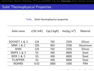
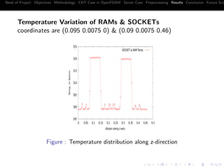
2](https://image.slidesharecdn.com/aee0f474-5b0a-42dd-941b-97a5a7f5f6f9-150626114941-lva1-app6892/85/Avinash_PPT-8-320.jpg)
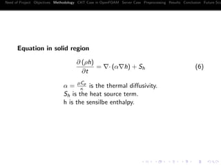
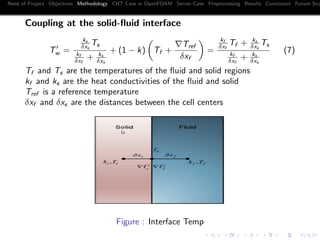

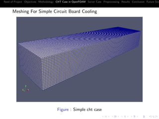
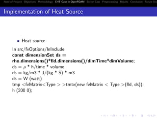


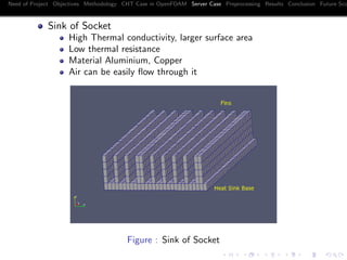
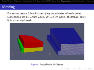
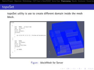

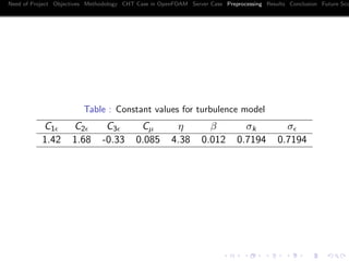


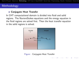
This document describes a conjugate heat transfer analysis of an electronics cooling system using OpenFOAM. It outlines the objectives to develop a CFD model for CHT analysis and validate it with experiments. The methodology section describes the governing equations solved for fluid and solid regions as well as the interface coupling. A simple circuit board cooling case is modeled and tested. Additionally, a server cooling case is proposed with details on geometry, meshing, boundary conditions and results showing temperature distributions.