Download to read offline

![G.Dinesh kumar, D.Gowri Shankar, D.Balaji / International Journal of Engineering Research
and Applications (IJERA) ISSN: 2248-9622 www.ijera.com
Vol. 3, Issue 1, January -February 2013, pp.1955-1960
made for computation. The following boundary In this project seeing all these analysis and
condition has been assigned. For modelling purpose numerical simulations we conclude that air breathing
oxygen velocity inlet boundary condition has been engine (scramjet engine) found to show better result
assigned for the inlet domain and pressure outlet using kerosene fuel at 8.8 Mach and 21500 Pascal
condition has been assigned to the outlet domain. when fuel injected by strut. The ejection velocity
Other boundary condition includes the default hard finally we got near 4400m/s, which comes around 13
interior of the wall created using Gambit. The Mach. This shows combustor is performing in Hyper-
boundary conditions are given in the table 4.1 for the sonic regimes
inlet and outlet.
V. FUTURE SCOPE OF WORK
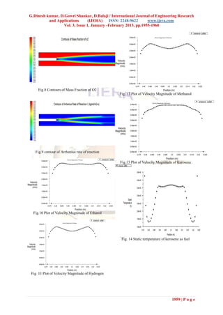
III. RESULTS AND DISCUSSIONS The work done gives a satisfactory result
A comparative histogram showing exit with present combustor model and for more concise
velocities of scramjet combustor for various fuels are dealing we can change some design parameters. The
shown fig 6.6e. In that plot kerosene found to be future scopes in this work are:
most efficient, the next lays ethanol, then methanol. The problem we solved is 2D and single
Hydrogen is pollution free fuel but not suitable for air plane mixing is analyzed. In future we can extend to
breathing engines at hypersonic velocities. The plots 3D, and double plane mixing is possible. We can
clearly show that kerosene is best efficient fuel for predict the flow at each nook and corner of
our combustor model. The exit velocity found to combustor.
increase with respect to time in fig .13 We analyzed for a fuel velocity of 660m/s. In
From the plot, the next efficient fuel is ethanol, future we shall do it by changing velocities of fuel
having 6 hydrogen bonds. Based the number of and air flow. It may give a better understanding of
hydrogen bond, the performance is rated. The fuel performance at various ranges.
numerical investigation also shows a similar result. New type of injector other than strut such as
Methanol having 4 hydrogen bonds showing results aerodynamic, ramp based or cantilever shall be
lesser than ethanol. Hydrogen stands last in the employed to see results.
analysis. The performance results of analysis shows a We defined our fuel temperature at injector.
very lower velocity magnitude for hydrogen fuel. In alternate we can specify the interior and exterior
wall temperature of the combustor.
IV. CONCLUSION
Designs for hypersonic engines have been REFERENCES
around since the early 1900’s. Ramjet technology [1] Ahmed, A., and Briec, E., ―Overview of
has been developing over the past eight decades and, CFD in automotive engine combustion‖,
except for marginal improvements, has been shown Network Newsletter, Vol-1, No.-3, Dept.of
to be suited for atmospheric flight speeds up to Mach Engine Engineering, Renault, January, 2002,
5. The desire for faster, more efficient engines gave pp. 17-20.
birth to the idea of a scramjet, utilizing supersonic [2] Ananias, T., ―A numerical approach for the
combustion and potentially expanding the speed simulation of non-premixed counter flow
envelope to the Mach 15 range. The promise of flames and reacting mixing layer‖,
covering the entire planet at high speed from Institution for Mathematics and it’s
horizontal takeoff for both civil and military aircraft Applications Publication,Vol-3, 1999-2000,
is an attractive prospect. However, along with new pp. 1-2.
technology and discoveries also come new obstacles [3] Arunajatesan, S., and Sinha, N., ―Large eddy
to be addressed. simulations of supersonic impinging jet flow
In order to study the establishment of the fields‖, AIAA 2002-4287, proceedings of 38
major flow features in a generic scramjet combustor AIAA/ASME/SAE/ASEE Joint Propulsion
several numerical simulations were carried out. A Conf. and Exhibit, Vol-1, July 7-10, 2002,
question still prevails in efficient fuel for hypersonic pp. 1-9.
regions. We considered 4 fuels for our analysis [4] Bai, H.C, Le, J.L, Zhang, Z.C, Goldfield,
(Hydrogen, kerosene, ethanol & methanol). M.A, Nestoulia, R.V., and Starov, A.V, “
On comparing performance of all the fuels, Methodical aspects of investigation of
we concluded that kerosene has higher ejection kerosene ignition and combustion in a
velocity. The reason is number of hydrogen bonds. scramjet model”,Report of Centre of
Breaking up of hydrogen bonds releases heat energy, Aerodynamic Research and
since kerosene has several hydrogen bonds (C12H23) Development,China, Vol-13,July, 2002, pp.
the energy released is much higher than other fuel 101-105.
under specified operating conditions. [5] Behera, and Chakraborty, D “Numerically
studied the flow field of a ramp cavity based
1957 | P a g e](https://image.slidesharecdn.com/kr3119551960-130219230900-phpapp02/85/Kr3119551960-3-320.jpg)
![G.Dinesh kumar, D.Gowri Shankar, D.Balaji / International Journal of Engineering Research
and Applications (IJERA) ISSN: 2248-9622 www.ijera.com
Vol. 3, Issue 1, January -February 2013, pp.1955-1960
scramjet combustor”, AIAA Paper No.
2006–3895 2010.
[6] Bhatia, R., and Sirignano, W.A., “One-
dimensional analysis of liquid fuelled
combustion instability”, Jr. of Prop. and
Power, Vol. 7, No. 6, November-December,
1991, pp. 652-660.
[7] Bogdanoff, D.W., “Advanced injection and
mixing techniques for scramjet
combustors”, Jr. of Prop. and Power, Vol.
10, No.2, March-April, 1994, pp. 183-187.
111
[8] Broadbent, E.G., “Calculation of inviscid 3- Fig.4 Contours of Velocity Magnitude after
d supersonic flows with heat and mass Combustion
addition”, Phil. Trans. Royal Soc. London,A
(1999) 357, 1999, pp. 2379- 2386
[9] Burkhardt, H., Sippel, M., Herbertz, A., and
Klevanski, J., “Comparative study of
kerosene and methane propellant engines
for reusable liquid booster stages”,
Proceedings of 4th Intl. Conf. on Launcher
Tech., December 3-6, 2002, pp. 1-12
[10] Charles. M., Gokhale, S.S, and Jayaraj, S.,
“The Nonreactive mixing study injector of a
scramjet swept-strut fuel injector”, Jr. of
Aerospace Sciences and Technologies , Vol
58, No 4, November, 2006, pp. 1-7
11. Table and Figure Fig.5 Contours of Velocity Magnitude after
Combustion
Fig.1 A generic scramjet combustor with centrally
located Fuel injector strut. (From NASA Contractor
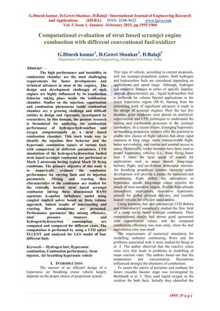
Fig.6 Contours of Mass Fraction of co2
Report 187467)
Fig.3 Combustor boundary conditions
Fig.7 Contours of Mass Fraction of H2 o
1958 | P a g e](https://image.slidesharecdn.com/kr3119551960-130219230900-phpapp02/85/Kr3119551960-4-320.jpg)


The document presents a computational analysis of strut-based scramjet engine combustion using various fuels, notably hydrogen and hydrocarbons, assessing their performance for hypersonic applications. Various computational fluid dynamics (CFD) simulations were conducted to evaluate combustion efficiency, fuel injection characteristics, and the overall performance of different fuels, revealing kerosene to be the most efficient due to its higher number of hydrogen bonds. The study concludes by highlighting future research avenues such as improving injector designs and extending simulations to three-dimensional models.


