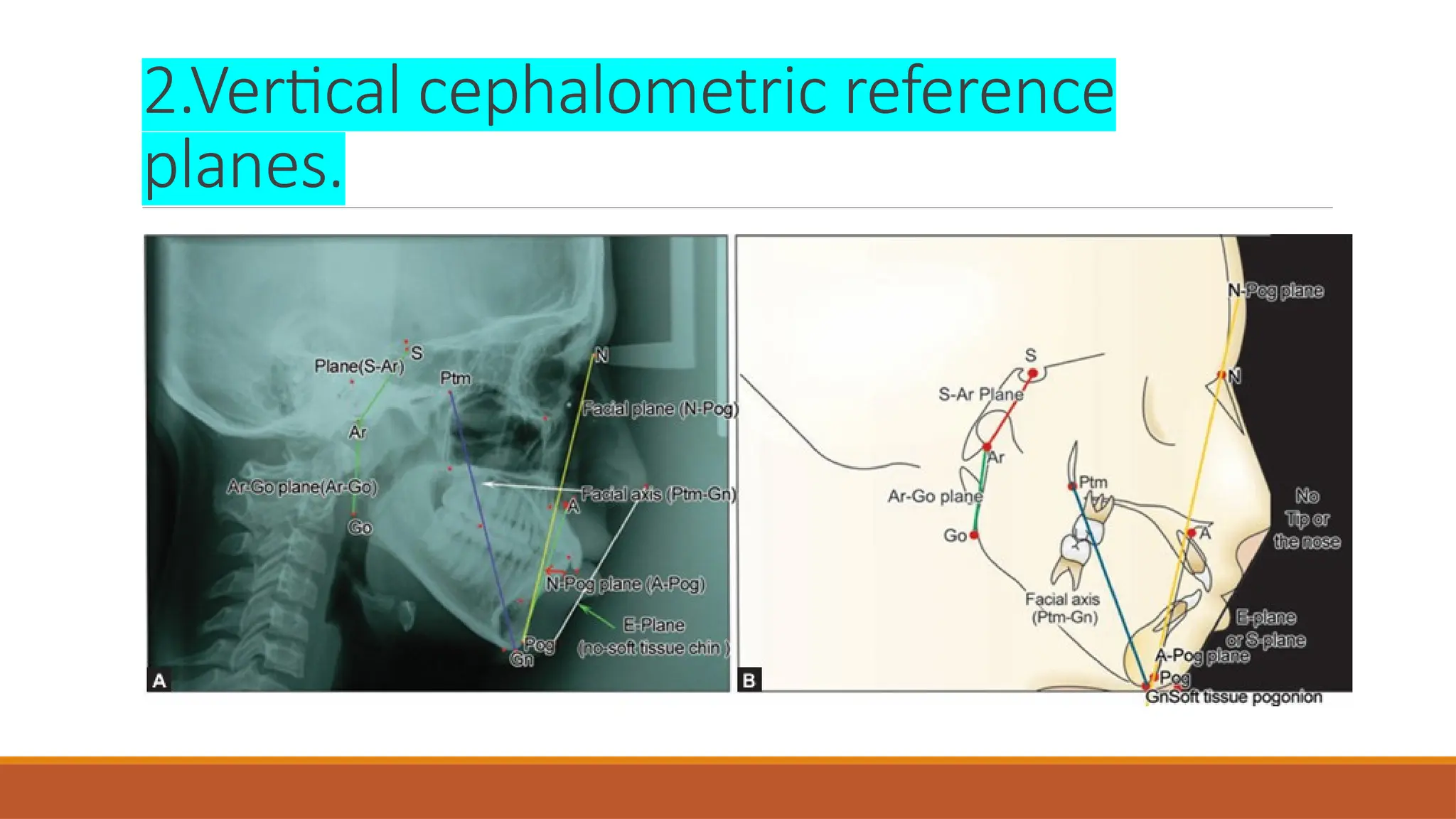
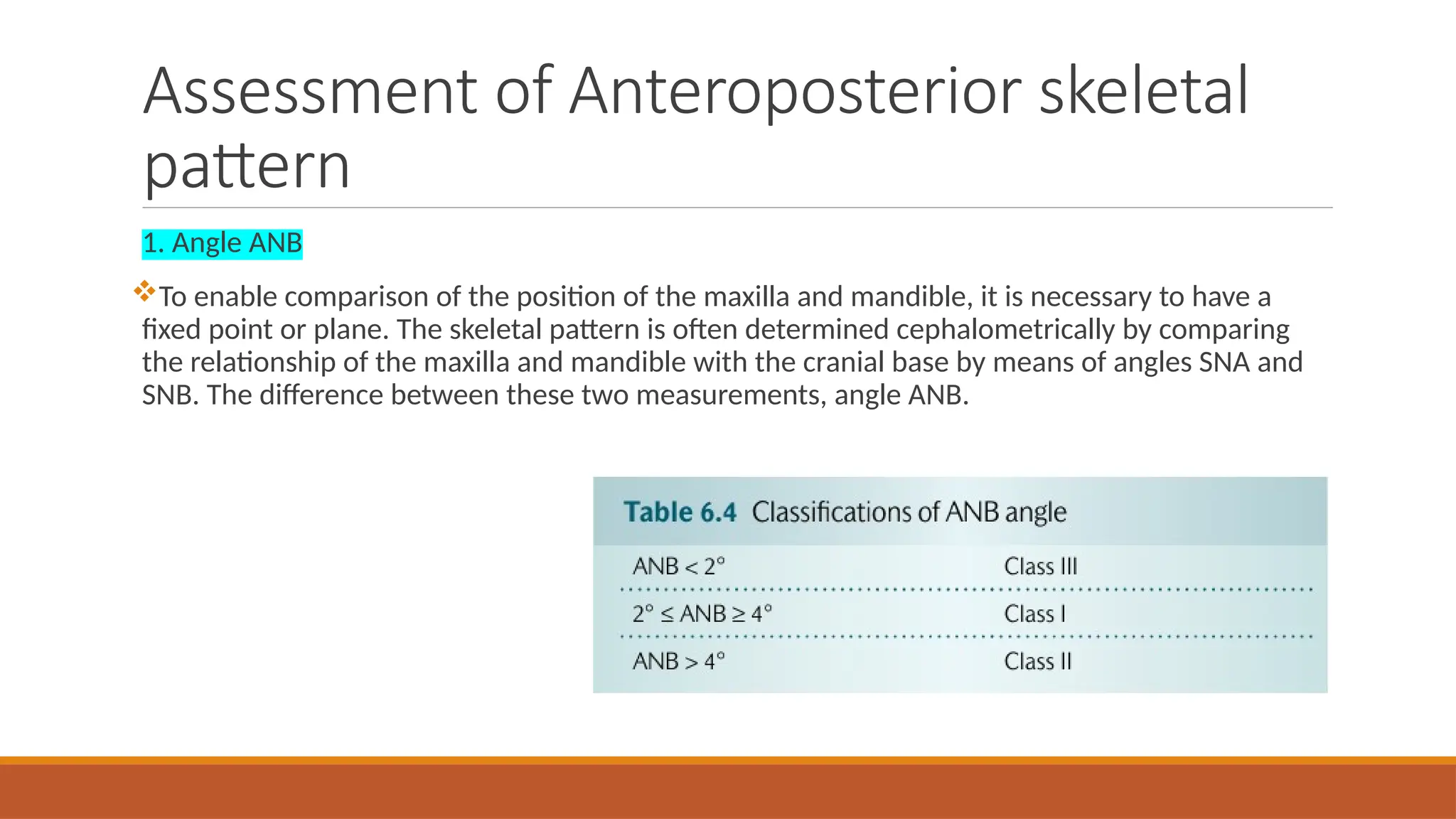
Cephalometric Radiograph:
Orthodontic Applications
BY: DR. MOHAMMED ALMOOSAWI
Cephalometric
Cephalometric radiographs are used in orthodontic diagnosis to evaluate the pretreatment
dental and facial relationship of the patient. They are also used to evaluate changes during
treatment and to assess tooth movement and facial growth at the end of the treatment.
On the cephalometric film, teeth can be related to one another, to the jaw in which they reside
and to cranial structures. Th e maxilla and mandible can be related to one another and to other
structures in the cranium. Th e soft tissue profile can also be evaluated.
Cephalometric analysis is one among various diagnostic aids. Orthodontic diagnosis is not
possible only on the basis of cephalometry. Cephalometric analysis is an important aid in
orthodontic diagnosis only if its findings are correctly and wisely interpreted with the help of
other diagnostic aids.
TYPES
There are two types of cephalograms:
1. Lateral Cephalogram : Lateral cephalogram provides a lateral view of the skull. It is taken
with the head in a standardized reproducible position at a specified distance from the source
of the X-ray. Lateral cephalogram is commonly used for cephalometric analysis.
2. Frontal Cephalogram : This provides an anteroposterior view of the skull. It is generally used
to assess symmetry of the face.
TYPES
The cephalostat
Standardization is required to enable comparison of cephalometric radiographs from one
patient at different time points or from different individuals. To achieve this, the cephalostat was
developed by B. Holly Broadbent in the period after the First World War.
The cephalostat consists of an X-ray machine set at a fixed distance from ear posts, which fit
into the patient’s external auditory meatus. The central beam of the machine is directed
towards the ear posts, which also serve to stabilize the patient’s head.
 The position of the head in the vertical axis is standardized by ensuring that the Frankfort
plane is horizontal. This can be done by manually positioning the patient or, alternatively, by
placing a mirror some distance away level with the patient’s head and asking him or her to look
into their own eyes. This is called the natural head position. It is normal practice to cone down
the area exposed so that the skull vault is not routinely included in the X-ray beam.
Difficulties in standardizing the distances from the tube to the patient (usually between 1.5 to
1.8 m) and from the patient to the film (usually around 30 cm) mean some magnification,
usually around 7–8%, is inevitable with a lateral cephalometric film.
To allow estimation of the magnification and thus the comparability of different films, it is
helpful if a scale is included in the view. It is essential that the magnification for a particular
cephalostat is standardized if comparison between radiographs is required. To give a better
definition of the soft tissue outline of the face an aluminium wedge is positioned to attenuate
the beam in that area, although this is required less frequently with newer digital systems.
The cephalostat
The cephalostat
Indications for cephalometric evaluation
1. Aid to diagnosis and treatment planning
It is possible to carry out successful orthodontic treatment without taking a cephalometric
radiograph, particularly in Class I malocclusions. However, cephalometric analysis may provide
useful information for assessing the aetiology of malocclusion and for planning treatment.
The benefit to the patient in terms of the additional information gained must be weighed against
the radiation dose.
 Pre-treatment lateral cephalometric radiographs may be best limited to patients with a skeletal
discrepancy and/or where anteroposterior movement of the incisors is planned.
In a small proportion of patients it may be helpful to monitor growth with serial cephalometric
radiographs to optimize the planning and timing of treatment. Again, the additional radiation
dosage to the patient must be justifiable and, where possible, other methods of growth monitor
ing that do not requireionising radiation should be used.
2. Pre-treatment record
A lateral cephalometric radiograph is useful in providing a baseline record prior to the
placement of appliances, particularly where growth modification or movement of the upper and
lower incisors is planned.
Indications for cephalometric evaluation
3. Monitoring treatment progress
In the management of severe malocclusions, where tooth movement is occurring in all three
planes of space (e.g. treatments involving functional appliances or upper and lower fixed
appliances), it may be helpful to take a lateral cephalometric radiograph during treatment to
monitor incisor inclinations and anchorage require ments.
A lateral cephalometric radiograph taken during treatment to assess treatment progress may
also provide information about the movement of unerupted teeth and upper incisor root
resorption. However, intra-oral images are preferred as greater detail is gained with lower
radiation dose
Indications for cephalometric evaluation
4.End of orthodontic treatment
For patients with severe malocclusions, a lateral cephalometric radiograph may be taken near
the end of active treatment to check all treatment objectives have been met and to aid planning
of retention.
Post-treatment lateral cephalometric radiographs are usually restricted to patients where there
is uncertainty around the stability of the out come as a result of the treatment methods used, or
a concern around future unfavourable growth.
Indications for cephalometric evaluation
5. Research purposes
A great deal of information has been obtained about growth and development by longitudinal
studies, which involved taking serial cephalometric radiographs from birth to the late teens or
beyond.
While the data provided by previous investigations are still used for reference purposes, it is no
longer ethically possible to repeat this type of study due to the risks associated with ionising
radiation.
However, views taken routinely during the course of orthodontic diagnosis and treatment for
clinical care may be used to study the effects of growth and treatment if the necessary consent
and ethical approval are obtained.
Indications for cephalometric evaluation
Evaluating a cephalometric radiograph
Before starting a tracing, it is important to examine the radiograph for any abnormalities or
pathology. For example, a pituitary tumour could result in an increase in the size of the sella
turcica.
There are two types of tracing:
1. Hand trace
2. Digitization
Hand tracing
In order to be able to derive meaningful information, an accurate and systematic approach is
required which also involves selecting the right conditions and equipment for the task.
The tracing should be carried out in a darkened room on a light viewing box. All but the area
being traced should be shielded to block out any extraneous light.
 Proprietary acetate sheets are the best medium as their transparency facilitates landmark
identification.
 A sharp pencil should be used. A 0.3 mm leaded propelling pencil is recommended to remove
the need for a pencil sharpener.
The acetate sheet should be secured onto the film with masking tape, which does not leave a
sticky residue when removed. The tracing should be oriented in the same position as the patient
was when the radiograph was taken, that is, with the Frankfort plane horizontal.
Stencils can be used to obtain a neat outline of the incisor and molar teeth. However, too much
artistic licence can lead to inaccuracies, particularly if the crown root angle of a tooth is not
‘average’.
 For landmarks which are bilateral, an average of the two should be taken unless they are
directly superimposed.
 With a careful technique, tracing errors should be of the order of ± 0.5 mm for linear
measurements and ± 0.5° for angular measurements.
 It is a valuable ‘learning experience’ to trace the same radiograph on two separate occasions
and compare the tracings. This helps to reduce the temptation to place undue emphasis upon
small variations from normal cephalometric values.
Hand tracing
Digitization
Information from a conventional hard copy lateral cephalometric film can be entered into a
computer by means of a digitizer, comprising an illuminated radiographic viewing screen
connected to the computer and a cursor to record the horizontal and vertical (x, y) coordinates
of cephalometric points and bony and soft tissue outlines.
 For digital radiographs the points can be entered directly by a mouse click. Specialized
software can then be employed to produce a tracing and/or the analysis of choice.
 Studies have shown digitizing to be as accurate as tracing a radiograph by hand and with the
increasing use of digital radiographs this has now become the norm. Digitizing is particularly
useful for research, as any number of radiographs can be entered, superimposed, and/or
compared statistically.
CEPHALOMETRIC LANDMARKS
Cephalometry makes use of certain landmarks or points on the skull, which are used for quantitative analysis
and measurements. The landmarks used in cephalometrics are of two broad categories:
1. hard tissue landmarks and
2. soft tissue landmarks.
The hard tissue landmarks can be anatomic or derived. Some of the hard tissue landmarks are unilateral while
others are bilateral. Cephalometric landmarks are classified as follows :
A. Anatomic cephalometric landmarks
B. Derived cephalometric landmarks.
Anatomic These landmarks represent the actual anatomic structures of the skull. They may be unilateral or
bilateral.
Derived These are landmarks that have been obtained secondarily from anatomic structures in a lateral
cephalogram.
CEPHALOMETRIC LANDMARKS
Hard Tissue Landmarks
Nasion (N)
Code/Abbreviation: Nasion is abbreviated as N (Capital alphabet)
Definition: Nasion is the most anterior point of frontonasal outline in the midline.
 Orbitale (Or)
Code/Abbreviation: Orbitale is abbreviated as Or (Capital alphabet O followed by small r)
 Definition: The lowest point on the inferior bony margin of the orbit.
Anterior Nasal Spine (ANS)
Code: Anterior nasal spine is abbreviated as ANS (all capital letters).
 Definition: Anterior nasal spine is the tip of bony anterior nasal spine in the midline or median plane.
Point A (A)
Code: Point A is abbreviated as point A itself.
Definition: Point A is the deepest point on the curved bony outline between the anterior nasal spine
(ANS) and prosthion.
Prosthion (Pr)
Code: Prosthion is abbreviated as Pr (Capital P followed by small r).
Definition: It is the lower most anterior point of alveolar process of pre-maxilla in the midline
between two central incisors
Hard Tissue Landmarks
Anterior Point of Occlusion (APOcc)
Code: APOcc (Capital APO followed by double small c).
Definition: Anterior point of occlusal plane is the midpoint in the incisors overbite in the occlusion.
Infradentale (Id)
Code: Infradentale is abbreviated as Id (Capital I followed by small d).
Definition: Infradentale is the highest anterior point of the alveolar process of mandible between two central
incisors in midline.
Point B
Code: Point B is abbreviated as point B itself.
Definition: It is the deepest point of curvature on the contour of mandibular alveolar process in the middle
between infradentale and pogonion.
Hard Tissue Landmarks
Pogonion (Pog)
Code: Pogonion is abbreviated as Pog (Capital P followed by small o and g).
Definition: Pogonion is the most anterior point of the bony chin in the midline.
Gnathion (Gn)
Code: Gnathion is abbreviated as Gn (Capital G followed by small n).
Definition: It is the most anterior and inferior point of the bony chin. It is constructed by intersecting a line drawn
perpendicularly to the line connecting menton and pogonion with bony outline.
According to Graig: Gnathion is the point of intersection of two planes.
According to Muzi and May: Gnathion is the lower point of the chin.
According to AM Schwarz: Gnathion is the lowest point of the chin.
According to Martin Saller: It is located in the midline of the mandible, where the anterior line in the outline of the chin
merges with the body of the mandible.
Hard Tissue Landmarks
Menton (Me)
Code: Menton is abbreviated as Me (Capital M followed by small e).
Definition: According to Krogman and Sassouni, Menton is the most caudal point in the outline of the
symphysis. It is regarded as the lowest point of the mandible.
Sella (S)
Code: Sella is abbreviated as S (capital letter ‘S’).
Definition: Sella is the midpoint of sella turcica or hypophyseal fossa or pituitary fossa.
Se
Code: Se is abbreviated as Se (Capital S followed by small e).
Definition: Se is the mid-entrance point of sella turcica or pituitary fossa.
Hard Tissue Landmarks
Pterygomaxillary Fissure (Ptm)
 Code: Pterygomaxillary fissure is abbreviated as Ptm (Capital P followed by small t and m).
 Definition: It is the intersection of the inferior border of the foramen rotundum with the
posterior wall of the pterygomaxillary fissure.
Posterior Nasal Spine (PNS)
Code: Posterior nasal spine is abbreviated as PNS (all capital letters).
Definition: It is the intersection of a continuation of the anterior wall of the pterygopalatine
fossa and the floor of the nose.
Hard Tissue Landmarks
Posterior Point of Occlusion (PPOcc)
Code: Posterior point of occlusion is abbreviated as PPOcc (capital PPO followed by small double c).
Definition: Posterior point for the occlusal plane is the most distal point of contact between the most
posterior molar in occlusion.
Articulare (Ar)
Code: Articulare is abbreviated as Ar (capital A followed by small r). It was introduced by Bjorio (1947).
Definition: Articulare is the point of intersection of the posterior margin of the ascending ramus and the outer
margin of the cranial base.
Condylion (Cd)
Code: Condylion is abbreviated as Cd (Capital C followed by small d).
Definition: It is the superior most point of the head of the condyle of the mandible.
Hard Tissue Landmarks
Gonion (Go)
Code: Gonion is abbreviated as Go (Capital G followed by small o).
Definition: Gonion is the intersection of the lines tangent to the posterior margin of the ascending ramus
and the mandibular base.
Porion (Po)
Code: Porion is abbreviated as Po (Capital P and small o)
Definition: It is the midpoint on the upper edge of the porus acusticus externus located by means of the
metal rods on the cephalometer.
Basion (Ba)
Code: Basion is abbreviated as Ba (Capital B followed by small a).
Definition: Basion is the lowest point on the anterior margin of the foramen magnum in the midline.
Hard Tissue Landmarks
Soft Tissue Landmarks
1.HORIZONTAL CEPHALOMETRIC REFERENCE
PLANES .
A. S-N plane
B. Se-N plane
C. F-H plane
D. Occlusal plane
E. Palatal plane
F. Mandibular plane.
2.VERTICAL CEPHALOMETRIC REFERENCE
PLANES.
A. A-Pog line
B. Facial plane
C. Facial axis
D. E-plane
E. S-Ar plane
F. Ar-Go plane.
Cephalometric Reference Planes
S-N Plane
 It is the plane formed by the line connecting sella turcica (midpoint of hypophyseal fossa) and
the nasion (anterior point of frontonasal suture).
Significance: It represents the anteroposterior extent of anterior cranial base.
Se-N Plane
It is the plane formed by the line connecting Se (mid entrance point of pituitary fossa) and the
nasion (anterior point of frontonasal suture).
Significance: As S-N plane, it also expresses the anteroposterior extent of anterior cranial base.
1.Horizontal cephalometric reference
planes .
F-H Plane
Frankfort-Horizontal plane is the plane that connects the lowest point of the orbit (orbitale) to
the superior point of the external auditory meatus (Porion).
Significance: It is horizontal cephalometric reference plane used to assess horizontal growth
during the analysis.
Occlusal Plane (APOcc–PPOcc)
Occlusal plane is formed by a line connecting anterior point of occlusion (APOcc) to the
posterior point of occlusion (PPOcc).
Significance: It has significant role in the assessment of horizontal growth pattern.
1.Horizontal cephalometric reference
planes .
Palatal Plane (ANS-PNS Plane)
 Palatal plane is formed by the line joining the point anterior nasal spine (ANS) to the posterior
nasal spine (PNS).
Significance: Growth pattern assessment.
Mandibular Plane/Me-Go Plane
It is the plane that connects the point Me (Menton) to the point Go (Gonion).
Significance: Growth pattern assessment.
1.Horizontal cephalometric reference
planes .
1.Horizontal cephalometric reference
planes .
A-Pog Line
It is a line from point A on the maxilla to pogonion on the mandible.
Facial Plane
It is a line from the anterior point of the frontonasal suture (nasion) to the most anterior point of
the mandible (pogonion).
Facial Axis
A line from Ptm point to cephalometric gnathion.
E-Plane
E-plane is also called esthetic plane and it is a line between the most anterior point of the soft
tissue nose and chin.
2.Vertical cephalometric reference
planes.
S-Ar Plane
It is the plane between the sella point (center of sella turcica) and the Ar (articulare) point.
 Significance: This plane represents the lateral extent of cranial base.
Ar-Go Plane
Ar-Go plane is formed by the line connecting from articulare (Ar) to the gonion (Go).
 Significance: This plane is important in the determination of length of ramus.
2.Vertical cephalometric reference
planes.
2.Vertical cephalometric reference
planes.
Assessment of Anteroposterior skeletal
pattern
1. Angle ANB
To enable comparison of the position of the maxilla and mandible, it is necessary to have a
fixed point or plane. The skeletal pattern is often determined cephalometrically by comparing
the relationship of the maxilla and mandible with the cranial base by means of angles SNA and
SNB. The difference between these two measurements, angle ANB.
1. Angle ANB
However, this approach has two assumptions: (1) the cranial base, as indicated by the line SN,
is a reliable basis for comparison; and (2) points A and B are indicative of maxillary and
mandibular basal bone.
As previously indicated, A and B points can be affected by changes in incisor root position and
this should be remembered when using SNA, SNB, and ANB to assess treatment changes.
 Variations in the position of nasion, particularly anteroposterior changes, affect angles SNA
and SNB and thus their relationship in ANB. Hence, an increase or reduction in SNA from the
average value could be due to either a discrepancy in the position of the maxilla (point A) or
nasion.
Assessment of Anteroposterior skeletal
pattern
1. Angle ANB
To compensate for the effect of an aberrant nasion position on ANB, a modification called the
‘Eastman correction’ is suggested (Fig. 6.7). This is only applied to cases with a change in the
position of the nasion, indicated by a normal angle between the maxillary plane and sella–
nasion line (8° ± 3°). An angle value outside this range indicates the position of the sella is at
fault and because this affects the SNA and SNB values to the same extent, the ANB value does
not require correction.
Assessment of Anteroposterior skeletal
pattern
1. Angle ANB
The ANB difference of 6° suggests a mild Class II skeletal pattern. However, if the ANB
difference is corrected, the new value of 5° suggests a Class I skeletal pattern based on the
Eastman Standard values.
To perform the correction:
 • If SNA is increased: for every degree that SNA is greater than 81°, subtract 0.5° from ANB.
• If SNA is reduced: for every degree that SNA is less than 81°, add 0.5° to ANB
Assessment of Anteroposterior skeletal
pattern
2. Nasion perpendicular
Another popular cephalometric method for assessing anteroposterior jaw relations arises from the
McNamara analysis. A line is drawn inferiorly from the nasion perpendicular to the Frankfort plane
(nasion–perpendicular) and this can be used to estimate maxillary and mandibular positions using
point A and pogonion respectively.
The method is as follows:
1. The nasion perpendicular is constructed by drawing a line perpendicular to the Frankfort plane,
extending inferiorly from the nasion.
2. The distance from the point A perpendicular to this line is measured to assess the maxillary
position.
3. The distance from the pogonion perpendicular to this line is measured to assess the mandibular
position.
Assessment of Anteroposterior skeletal
pattern
2. Nasion perpendicular
This method has similarities to the clinical assessment using the zero meridian.
 The main limitations in using the nasion perpendicular arise from location of the Frankfort
plane and the potential variation in the position of the nasion.
Alternatively, an approach that avoids the cranial base and nasion, for example, the Ballard
conversion or the Wits analysis can be used to supplement the above analyses, particularly
where the cephalometric findings are at variance with the clinical assessment.
3. Ballard conversion
Ballard’s method uses the incisors as indicators of the relative position of the maxilla and
mandible.
The aim is to tilt the teeth to their normal angles (thus eliminating any dento-alveolar
compensation) with the result that the residual overjet will indicate the relationship of the
maxilla to the mandible.
Assessment of Anteroposterior skeletal
pattern
3. Ballard conversion
The method is as follows:
1. Trace the outline of the maxilla, the mandibular symphysis, the incisors, and the maxillary
and mandibular planes
2. Mark the ‘rotation points’ of the incisors one-third of the root length away from the root
apex.
3. Rotating around the point marked, reposition the upper incisor at an angle of 109° to the
maxillary plane.
4. Repeat for the lower incisor—in this case, reposition lower incisor to 100° to allow for the
maxillary mandibular planes angle of 20° .
 The residual overjet reflects the underlying skeletal pattern.
In the case the lower incisor edge lies distal to the cingulum plateau of the uppers with an
increased overjet, indicating a mild Class II skeletal pattern.
The Ballard conversion should not be confused with a prognosis tracing , which aims to assess
the scope for orthodontic camouflage in patients with an underlying skeletal discrepancy.
3. Ballard conversion
4. Wits analysis
This analysis compares the relationship of the maxilla and mandible with the occlusal plane. There are
several definitions of the occlusal plane, but for the purposes of the Wits analysis it is taken to be a line
drawn between the cusp tips of the molars and premolars (or deciduous molars), known as the FOP.
Perpendicular lines from both point A and point B are drawn to the FOP to give points AO and BO. The
distance between AO and BO is then measured.
Assessment of Anteroposterior skeletal
pattern
4. Wits analysis
The method is as follows:
1. The FOP is constructed.
2. A perpendicular line is drawn from point A and point B to the FOP to give points AO and BO.
3. The distance between AO and BO is measured.
The average values are −1 mm (± 1.9 mm) for males and 0 mm (± 1.77 mm) for females.
The main drawback to the Wits analysis is that the FOP is not easy to locate, which affects the
accuracy and reproducibility of the Wits analysis. A slight difference in the angulation of the FOP
can have a marked effect on the relative positions of AO and BO.
Assessing the vertical skeletal
relationship
There are many different ways of assessing vertical skeletal proportions. The more commonly
used include the following.
1. The maxillary–mandibular planes angle (MMPA). The average MMPA is 27 ± 4°.
2. Frankfort mandibular planes angle (FMPA). The average angle is 28 ± 4°. However, the
maxillary plane is easier to locate accurately and is therefore more widely used.
3. 3- Anterior and posterior face heights .
Anterior and posterior face heights are also used as a measure of vertical facial relationships:
 Total anterior face height (TAFH) extends from nasion to menton, with both lines constructed perpendicular
to the maxillary plane (mean 119 mm in an adult male). TAFH is further subdivided into:
• Upper anterior face height (UAFH); nasion to maxillary plane (mean 54 mm);
• Lower anterior face height (LAFH); maxillary plane to menton (mean 65 mm); and
 Total posterior face height (TPFH) extends from sella to gonion, with both lines constructed perpendicular
to the maxillary plane (mean 79 mm in an adult male). TPFH is therefore subdivided into:
• Upper posterior face height (UPFH); sella to maxillary plane (mean 46 mm);
• Lower posterior face height (LPFH); maxillary plane to gonion (mean 33 mm);
The TPFH should be approximately 65% of the TAFH.
Assessing the vertical skeletal
relationship
3. The anterior facial proportion.
It should be noted that the TPFH (unlike the TAFH) is influenced by a particularly superior or
inferior position of sella and this will affect the TPFH/TAFH ratio. Referring to the SN–maxillary
plane angle can cheque the relative position of sella within the cranium.
 The LAFH should be approximately 55% of the TAFH.
Incisor relationship
The average value for the angle formed between the upper incisor and the maxillary plane is
109 ± 6°, and for the lower incisor and the mandibular plane is 93 ± 6° in Caucasians. It should
be remembered that there is ethnic variation in these norms and more proclination is expected
for other racial groups. The inter-incisal angle, formed by intersecting the lines through the
upper and lower incisors, is important for overbite correction.
The ‘normal’ value for the lower incisor angle is for an individual with an average MMPA of 27°.
It has been suggested that there is a relationship between the MMPA and the lower incisor
angle: as the MMPA increases, the lower incisors become more retroclined. As the sum of the
average MMPA (27°) and the average lower incisor angle (93°) equals 120°, an alternative way of
deriving the ‘average’ lower incisor angulation for an individual is to subtract the MMPA from
120°:
 Lower incisor angle = 120° – MMPA.
Prognosis tracing
Sometimes it is helpful to be able to determine the type and amount of incisor movement
required to correct an increased or reverse overjet. Although the skeletal pattern will give an
indication, on occasion, compensatory proclination or retroclination (known as dento-alveolar
compensation) of the incisors, can create challenges when determining the scope for tooth
movement. In such cases it may be helpful to carry out a prognosis tracing. This involves
‘moving’ the incisor(s) to mimic the movements achievable with different treatment approaches
to help determine the best course of action for that patient.
Prognosis tracing
Soft tissue analysis
Careful analysis of the soft tissues is important, particularly if changes to incisor position are
planned and in diagnosis and planning prior to orthognathic surgery.
 As with other elements of cephalometric analysis, there are a large number of different analyses
of varying complexity. Some of the more commonly used analyses include:
1- The Holdaway line: This is a line from the soft tissue chin to the upper lip. In a well-proportioned
face this line, if extended, should bisect the nose.
2- Rickett’s E-plane: This line joins the soft tissue chin and the tip of the nose. In a balanced face
the lower lip should lie 2 mm (± 2 mm) posterior to this line with the upper lip positioned a little
further posteriorly to the line.
3- Facial plane: The facial plane is a line between the soft tissue nasion and the soft tissue chin. In a
well-balanced face the Frankfort plane should bisect the facial plane at an angle of about 86° and
point A should lie on it.
Soft tissue analysis
REFERENCE
1. an introduction to orthodontics by Simon J. Littlewood and Loura Mitchell fifth edition
2. ORTHODONTICS Principles and Practice by Basavaraj Subhashchandra Phulari second edition
3. Baghdad university lectures
Cephalometric Radiograph : Orthodontic applications.pptx

Cephalometric Radiograph : Orthodontic applications.pptx

  • 1.
  • 2.
    Cephalometric Cephalometric radiographs areused in orthodontic diagnosis to evaluate the pretreatment dental and facial relationship of the patient. They are also used to evaluate changes during treatment and to assess tooth movement and facial growth at the end of the treatment. On the cephalometric film, teeth can be related to one another, to the jaw in which they reside and to cranial structures. Th e maxilla and mandible can be related to one another and to other structures in the cranium. Th e soft tissue profile can also be evaluated. Cephalometric analysis is one among various diagnostic aids. Orthodontic diagnosis is not possible only on the basis of cephalometry. Cephalometric analysis is an important aid in orthodontic diagnosis only if its findings are correctly and wisely interpreted with the help of other diagnostic aids.
  • 3.
    TYPES There are twotypes of cephalograms: 1. Lateral Cephalogram : Lateral cephalogram provides a lateral view of the skull. It is taken with the head in a standardized reproducible position at a specified distance from the source of the X-ray. Lateral cephalogram is commonly used for cephalometric analysis. 2. Frontal Cephalogram : This provides an anteroposterior view of the skull. It is generally used to assess symmetry of the face.
  • 4.
  • 5.
    The cephalostat Standardization isrequired to enable comparison of cephalometric radiographs from one patient at different time points or from different individuals. To achieve this, the cephalostat was developed by B. Holly Broadbent in the period after the First World War. The cephalostat consists of an X-ray machine set at a fixed distance from ear posts, which fit into the patient’s external auditory meatus. The central beam of the machine is directed towards the ear posts, which also serve to stabilize the patient’s head.  The position of the head in the vertical axis is standardized by ensuring that the Frankfort plane is horizontal. This can be done by manually positioning the patient or, alternatively, by placing a mirror some distance away level with the patient’s head and asking him or her to look into their own eyes. This is called the natural head position. It is normal practice to cone down the area exposed so that the skull vault is not routinely included in the X-ray beam.
  • 6.
    Difficulties in standardizingthe distances from the tube to the patient (usually between 1.5 to 1.8 m) and from the patient to the film (usually around 30 cm) mean some magnification, usually around 7–8%, is inevitable with a lateral cephalometric film. To allow estimation of the magnification and thus the comparability of different films, it is helpful if a scale is included in the view. It is essential that the magnification for a particular cephalostat is standardized if comparison between radiographs is required. To give a better definition of the soft tissue outline of the face an aluminium wedge is positioned to attenuate the beam in that area, although this is required less frequently with newer digital systems. The cephalostat
  • 7.
  • 8.
    Indications for cephalometricevaluation 1. Aid to diagnosis and treatment planning It is possible to carry out successful orthodontic treatment without taking a cephalometric radiograph, particularly in Class I malocclusions. However, cephalometric analysis may provide useful information for assessing the aetiology of malocclusion and for planning treatment. The benefit to the patient in terms of the additional information gained must be weighed against the radiation dose.  Pre-treatment lateral cephalometric radiographs may be best limited to patients with a skeletal discrepancy and/or where anteroposterior movement of the incisors is planned. In a small proportion of patients it may be helpful to monitor growth with serial cephalometric radiographs to optimize the planning and timing of treatment. Again, the additional radiation dosage to the patient must be justifiable and, where possible, other methods of growth monitor ing that do not requireionising radiation should be used.
  • 9.
    2. Pre-treatment record Alateral cephalometric radiograph is useful in providing a baseline record prior to the placement of appliances, particularly where growth modification or movement of the upper and lower incisors is planned. Indications for cephalometric evaluation
  • 10.
    3. Monitoring treatmentprogress In the management of severe malocclusions, where tooth movement is occurring in all three planes of space (e.g. treatments involving functional appliances or upper and lower fixed appliances), it may be helpful to take a lateral cephalometric radiograph during treatment to monitor incisor inclinations and anchorage require ments. A lateral cephalometric radiograph taken during treatment to assess treatment progress may also provide information about the movement of unerupted teeth and upper incisor root resorption. However, intra-oral images are preferred as greater detail is gained with lower radiation dose Indications for cephalometric evaluation
  • 11.
    4.End of orthodontictreatment For patients with severe malocclusions, a lateral cephalometric radiograph may be taken near the end of active treatment to check all treatment objectives have been met and to aid planning of retention. Post-treatment lateral cephalometric radiographs are usually restricted to patients where there is uncertainty around the stability of the out come as a result of the treatment methods used, or a concern around future unfavourable growth. Indications for cephalometric evaluation
  • 12.
    5. Research purposes Agreat deal of information has been obtained about growth and development by longitudinal studies, which involved taking serial cephalometric radiographs from birth to the late teens or beyond. While the data provided by previous investigations are still used for reference purposes, it is no longer ethically possible to repeat this type of study due to the risks associated with ionising radiation. However, views taken routinely during the course of orthodontic diagnosis and treatment for clinical care may be used to study the effects of growth and treatment if the necessary consent and ethical approval are obtained. Indications for cephalometric evaluation
  • 13.
    Evaluating a cephalometricradiograph Before starting a tracing, it is important to examine the radiograph for any abnormalities or pathology. For example, a pituitary tumour could result in an increase in the size of the sella turcica. There are two types of tracing: 1. Hand trace 2. Digitization
  • 14.
    Hand tracing In orderto be able to derive meaningful information, an accurate and systematic approach is required which also involves selecting the right conditions and equipment for the task. The tracing should be carried out in a darkened room on a light viewing box. All but the area being traced should be shielded to block out any extraneous light.  Proprietary acetate sheets are the best medium as their transparency facilitates landmark identification.  A sharp pencil should be used. A 0.3 mm leaded propelling pencil is recommended to remove the need for a pencil sharpener. The acetate sheet should be secured onto the film with masking tape, which does not leave a sticky residue when removed. The tracing should be oriented in the same position as the patient was when the radiograph was taken, that is, with the Frankfort plane horizontal.
  • 15.
    Stencils can beused to obtain a neat outline of the incisor and molar teeth. However, too much artistic licence can lead to inaccuracies, particularly if the crown root angle of a tooth is not ‘average’.  For landmarks which are bilateral, an average of the two should be taken unless they are directly superimposed.  With a careful technique, tracing errors should be of the order of ± 0.5 mm for linear measurements and ± 0.5° for angular measurements.  It is a valuable ‘learning experience’ to trace the same radiograph on two separate occasions and compare the tracings. This helps to reduce the temptation to place undue emphasis upon small variations from normal cephalometric values. Hand tracing
  • 16.
    Digitization Information from aconventional hard copy lateral cephalometric film can be entered into a computer by means of a digitizer, comprising an illuminated radiographic viewing screen connected to the computer and a cursor to record the horizontal and vertical (x, y) coordinates of cephalometric points and bony and soft tissue outlines.  For digital radiographs the points can be entered directly by a mouse click. Specialized software can then be employed to produce a tracing and/or the analysis of choice.  Studies have shown digitizing to be as accurate as tracing a radiograph by hand and with the increasing use of digital radiographs this has now become the norm. Digitizing is particularly useful for research, as any number of radiographs can be entered, superimposed, and/or compared statistically.
  • 17.
    CEPHALOMETRIC LANDMARKS Cephalometry makesuse of certain landmarks or points on the skull, which are used for quantitative analysis and measurements. The landmarks used in cephalometrics are of two broad categories: 1. hard tissue landmarks and 2. soft tissue landmarks. The hard tissue landmarks can be anatomic or derived. Some of the hard tissue landmarks are unilateral while others are bilateral. Cephalometric landmarks are classified as follows : A. Anatomic cephalometric landmarks B. Derived cephalometric landmarks. Anatomic These landmarks represent the actual anatomic structures of the skull. They may be unilateral or bilateral. Derived These are landmarks that have been obtained secondarily from anatomic structures in a lateral cephalogram.
  • 18.
  • 19.
    Hard Tissue Landmarks Nasion(N) Code/Abbreviation: Nasion is abbreviated as N (Capital alphabet) Definition: Nasion is the most anterior point of frontonasal outline in the midline.  Orbitale (Or) Code/Abbreviation: Orbitale is abbreviated as Or (Capital alphabet O followed by small r)  Definition: The lowest point on the inferior bony margin of the orbit.
  • 20.
    Anterior Nasal Spine(ANS) Code: Anterior nasal spine is abbreviated as ANS (all capital letters).  Definition: Anterior nasal spine is the tip of bony anterior nasal spine in the midline or median plane. Point A (A) Code: Point A is abbreviated as point A itself. Definition: Point A is the deepest point on the curved bony outline between the anterior nasal spine (ANS) and prosthion. Prosthion (Pr) Code: Prosthion is abbreviated as Pr (Capital P followed by small r). Definition: It is the lower most anterior point of alveolar process of pre-maxilla in the midline between two central incisors Hard Tissue Landmarks
  • 21.
    Anterior Point ofOcclusion (APOcc) Code: APOcc (Capital APO followed by double small c). Definition: Anterior point of occlusal plane is the midpoint in the incisors overbite in the occlusion. Infradentale (Id) Code: Infradentale is abbreviated as Id (Capital I followed by small d). Definition: Infradentale is the highest anterior point of the alveolar process of mandible between two central incisors in midline. Point B Code: Point B is abbreviated as point B itself. Definition: It is the deepest point of curvature on the contour of mandibular alveolar process in the middle between infradentale and pogonion. Hard Tissue Landmarks
  • 22.
    Pogonion (Pog) Code: Pogonionis abbreviated as Pog (Capital P followed by small o and g). Definition: Pogonion is the most anterior point of the bony chin in the midline. Gnathion (Gn) Code: Gnathion is abbreviated as Gn (Capital G followed by small n). Definition: It is the most anterior and inferior point of the bony chin. It is constructed by intersecting a line drawn perpendicularly to the line connecting menton and pogonion with bony outline. According to Graig: Gnathion is the point of intersection of two planes. According to Muzi and May: Gnathion is the lower point of the chin. According to AM Schwarz: Gnathion is the lowest point of the chin. According to Martin Saller: It is located in the midline of the mandible, where the anterior line in the outline of the chin merges with the body of the mandible. Hard Tissue Landmarks
  • 23.
    Menton (Me) Code: Mentonis abbreviated as Me (Capital M followed by small e). Definition: According to Krogman and Sassouni, Menton is the most caudal point in the outline of the symphysis. It is regarded as the lowest point of the mandible. Sella (S) Code: Sella is abbreviated as S (capital letter ‘S’). Definition: Sella is the midpoint of sella turcica or hypophyseal fossa or pituitary fossa. Se Code: Se is abbreviated as Se (Capital S followed by small e). Definition: Se is the mid-entrance point of sella turcica or pituitary fossa. Hard Tissue Landmarks
  • 24.
    Pterygomaxillary Fissure (Ptm) Code: Pterygomaxillary fissure is abbreviated as Ptm (Capital P followed by small t and m).  Definition: It is the intersection of the inferior border of the foramen rotundum with the posterior wall of the pterygomaxillary fissure. Posterior Nasal Spine (PNS) Code: Posterior nasal spine is abbreviated as PNS (all capital letters). Definition: It is the intersection of a continuation of the anterior wall of the pterygopalatine fossa and the floor of the nose. Hard Tissue Landmarks
  • 25.
    Posterior Point ofOcclusion (PPOcc) Code: Posterior point of occlusion is abbreviated as PPOcc (capital PPO followed by small double c). Definition: Posterior point for the occlusal plane is the most distal point of contact between the most posterior molar in occlusion. Articulare (Ar) Code: Articulare is abbreviated as Ar (capital A followed by small r). It was introduced by Bjorio (1947). Definition: Articulare is the point of intersection of the posterior margin of the ascending ramus and the outer margin of the cranial base. Condylion (Cd) Code: Condylion is abbreviated as Cd (Capital C followed by small d). Definition: It is the superior most point of the head of the condyle of the mandible. Hard Tissue Landmarks
  • 26.
    Gonion (Go) Code: Gonionis abbreviated as Go (Capital G followed by small o). Definition: Gonion is the intersection of the lines tangent to the posterior margin of the ascending ramus and the mandibular base. Porion (Po) Code: Porion is abbreviated as Po (Capital P and small o) Definition: It is the midpoint on the upper edge of the porus acusticus externus located by means of the metal rods on the cephalometer. Basion (Ba) Code: Basion is abbreviated as Ba (Capital B followed by small a). Definition: Basion is the lowest point on the anterior margin of the foramen magnum in the midline. Hard Tissue Landmarks
  • 27.
  • 28.
  • 29.
    1.HORIZONTAL CEPHALOMETRIC REFERENCE PLANES. A. S-N plane B. Se-N plane C. F-H plane D. Occlusal plane E. Palatal plane F. Mandibular plane. 2.VERTICAL CEPHALOMETRIC REFERENCE PLANES. A. A-Pog line B. Facial plane C. Facial axis D. E-plane E. S-Ar plane F. Ar-Go plane. Cephalometric Reference Planes
  • 30.
    S-N Plane  Itis the plane formed by the line connecting sella turcica (midpoint of hypophyseal fossa) and the nasion (anterior point of frontonasal suture). Significance: It represents the anteroposterior extent of anterior cranial base. Se-N Plane It is the plane formed by the line connecting Se (mid entrance point of pituitary fossa) and the nasion (anterior point of frontonasal suture). Significance: As S-N plane, it also expresses the anteroposterior extent of anterior cranial base. 1.Horizontal cephalometric reference planes .
  • 31.
    F-H Plane Frankfort-Horizontal planeis the plane that connects the lowest point of the orbit (orbitale) to the superior point of the external auditory meatus (Porion). Significance: It is horizontal cephalometric reference plane used to assess horizontal growth during the analysis. Occlusal Plane (APOcc–PPOcc) Occlusal plane is formed by a line connecting anterior point of occlusion (APOcc) to the posterior point of occlusion (PPOcc). Significance: It has significant role in the assessment of horizontal growth pattern. 1.Horizontal cephalometric reference planes .
  • 32.
    Palatal Plane (ANS-PNSPlane)  Palatal plane is formed by the line joining the point anterior nasal spine (ANS) to the posterior nasal spine (PNS). Significance: Growth pattern assessment. Mandibular Plane/Me-Go Plane It is the plane that connects the point Me (Menton) to the point Go (Gonion). Significance: Growth pattern assessment. 1.Horizontal cephalometric reference planes .
  • 33.
  • 34.
    A-Pog Line It isa line from point A on the maxilla to pogonion on the mandible. Facial Plane It is a line from the anterior point of the frontonasal suture (nasion) to the most anterior point of the mandible (pogonion). Facial Axis A line from Ptm point to cephalometric gnathion. E-Plane E-plane is also called esthetic plane and it is a line between the most anterior point of the soft tissue nose and chin. 2.Vertical cephalometric reference planes.
  • 35.
    S-Ar Plane It isthe plane between the sella point (center of sella turcica) and the Ar (articulare) point.  Significance: This plane represents the lateral extent of cranial base. Ar-Go Plane Ar-Go plane is formed by the line connecting from articulare (Ar) to the gonion (Go).  Significance: This plane is important in the determination of length of ramus. 2.Vertical cephalometric reference planes.
  • 36.
  • 37.
    Assessment of Anteroposteriorskeletal pattern 1. Angle ANB To enable comparison of the position of the maxilla and mandible, it is necessary to have a fixed point or plane. The skeletal pattern is often determined cephalometrically by comparing the relationship of the maxilla and mandible with the cranial base by means of angles SNA and SNB. The difference between these two measurements, angle ANB.
  • 38.
    1. Angle ANB However,this approach has two assumptions: (1) the cranial base, as indicated by the line SN, is a reliable basis for comparison; and (2) points A and B are indicative of maxillary and mandibular basal bone. As previously indicated, A and B points can be affected by changes in incisor root position and this should be remembered when using SNA, SNB, and ANB to assess treatment changes.  Variations in the position of nasion, particularly anteroposterior changes, affect angles SNA and SNB and thus their relationship in ANB. Hence, an increase or reduction in SNA from the average value could be due to either a discrepancy in the position of the maxilla (point A) or nasion. Assessment of Anteroposterior skeletal pattern
  • 40.
    1. Angle ANB Tocompensate for the effect of an aberrant nasion position on ANB, a modification called the ‘Eastman correction’ is suggested (Fig. 6.7). This is only applied to cases with a change in the position of the nasion, indicated by a normal angle between the maxillary plane and sella– nasion line (8° ± 3°). An angle value outside this range indicates the position of the sella is at fault and because this affects the SNA and SNB values to the same extent, the ANB value does not require correction. Assessment of Anteroposterior skeletal pattern
  • 42.
    1. Angle ANB TheANB difference of 6° suggests a mild Class II skeletal pattern. However, if the ANB difference is corrected, the new value of 5° suggests a Class I skeletal pattern based on the Eastman Standard values. To perform the correction:  • If SNA is increased: for every degree that SNA is greater than 81°, subtract 0.5° from ANB. • If SNA is reduced: for every degree that SNA is less than 81°, add 0.5° to ANB Assessment of Anteroposterior skeletal pattern
  • 43.
    2. Nasion perpendicular Anotherpopular cephalometric method for assessing anteroposterior jaw relations arises from the McNamara analysis. A line is drawn inferiorly from the nasion perpendicular to the Frankfort plane (nasion–perpendicular) and this can be used to estimate maxillary and mandibular positions using point A and pogonion respectively. The method is as follows: 1. The nasion perpendicular is constructed by drawing a line perpendicular to the Frankfort plane, extending inferiorly from the nasion. 2. The distance from the point A perpendicular to this line is measured to assess the maxillary position. 3. The distance from the pogonion perpendicular to this line is measured to assess the mandibular position. Assessment of Anteroposterior skeletal pattern
  • 44.
    2. Nasion perpendicular Thismethod has similarities to the clinical assessment using the zero meridian.  The main limitations in using the nasion perpendicular arise from location of the Frankfort plane and the potential variation in the position of the nasion. Alternatively, an approach that avoids the cranial base and nasion, for example, the Ballard conversion or the Wits analysis can be used to supplement the above analyses, particularly where the cephalometric findings are at variance with the clinical assessment.
  • 46.
    3. Ballard conversion Ballard’smethod uses the incisors as indicators of the relative position of the maxilla and mandible. The aim is to tilt the teeth to their normal angles (thus eliminating any dento-alveolar compensation) with the result that the residual overjet will indicate the relationship of the maxilla to the mandible. Assessment of Anteroposterior skeletal pattern
  • 47.
    3. Ballard conversion Themethod is as follows: 1. Trace the outline of the maxilla, the mandibular symphysis, the incisors, and the maxillary and mandibular planes 2. Mark the ‘rotation points’ of the incisors one-third of the root length away from the root apex. 3. Rotating around the point marked, reposition the upper incisor at an angle of 109° to the maxillary plane. 4. Repeat for the lower incisor—in this case, reposition lower incisor to 100° to allow for the maxillary mandibular planes angle of 20° .  The residual overjet reflects the underlying skeletal pattern.
  • 48.
    In the casethe lower incisor edge lies distal to the cingulum plateau of the uppers with an increased overjet, indicating a mild Class II skeletal pattern. The Ballard conversion should not be confused with a prognosis tracing , which aims to assess the scope for orthodontic camouflage in patients with an underlying skeletal discrepancy. 3. Ballard conversion
  • 49.
  • 50.
    4. Wits analysis Thisanalysis compares the relationship of the maxilla and mandible with the occlusal plane. There are several definitions of the occlusal plane, but for the purposes of the Wits analysis it is taken to be a line drawn between the cusp tips of the molars and premolars (or deciduous molars), known as the FOP. Perpendicular lines from both point A and point B are drawn to the FOP to give points AO and BO. The distance between AO and BO is then measured. Assessment of Anteroposterior skeletal pattern
  • 51.
    4. Wits analysis Themethod is as follows: 1. The FOP is constructed. 2. A perpendicular line is drawn from point A and point B to the FOP to give points AO and BO. 3. The distance between AO and BO is measured. The average values are −1 mm (± 1.9 mm) for males and 0 mm (± 1.77 mm) for females. The main drawback to the Wits analysis is that the FOP is not easy to locate, which affects the accuracy and reproducibility of the Wits analysis. A slight difference in the angulation of the FOP can have a marked effect on the relative positions of AO and BO.
  • 52.
    Assessing the verticalskeletal relationship There are many different ways of assessing vertical skeletal proportions. The more commonly used include the following. 1. The maxillary–mandibular planes angle (MMPA). The average MMPA is 27 ± 4°. 2. Frankfort mandibular planes angle (FMPA). The average angle is 28 ± 4°. However, the maxillary plane is easier to locate accurately and is therefore more widely used.
  • 54.
    3. 3- Anteriorand posterior face heights . Anterior and posterior face heights are also used as a measure of vertical facial relationships:  Total anterior face height (TAFH) extends from nasion to menton, with both lines constructed perpendicular to the maxillary plane (mean 119 mm in an adult male). TAFH is further subdivided into: • Upper anterior face height (UAFH); nasion to maxillary plane (mean 54 mm); • Lower anterior face height (LAFH); maxillary plane to menton (mean 65 mm); and  Total posterior face height (TPFH) extends from sella to gonion, with both lines constructed perpendicular to the maxillary plane (mean 79 mm in an adult male). TPFH is therefore subdivided into: • Upper posterior face height (UPFH); sella to maxillary plane (mean 46 mm); • Lower posterior face height (LPFH); maxillary plane to gonion (mean 33 mm); The TPFH should be approximately 65% of the TAFH. Assessing the vertical skeletal relationship
  • 55.
    3. The anteriorfacial proportion. It should be noted that the TPFH (unlike the TAFH) is influenced by a particularly superior or inferior position of sella and this will affect the TPFH/TAFH ratio. Referring to the SN–maxillary plane angle can cheque the relative position of sella within the cranium.  The LAFH should be approximately 55% of the TAFH.
  • 57.
    Incisor relationship The averagevalue for the angle formed between the upper incisor and the maxillary plane is 109 ± 6°, and for the lower incisor and the mandibular plane is 93 ± 6° in Caucasians. It should be remembered that there is ethnic variation in these norms and more proclination is expected for other racial groups. The inter-incisal angle, formed by intersecting the lines through the upper and lower incisors, is important for overbite correction. The ‘normal’ value for the lower incisor angle is for an individual with an average MMPA of 27°. It has been suggested that there is a relationship between the MMPA and the lower incisor angle: as the MMPA increases, the lower incisors become more retroclined. As the sum of the average MMPA (27°) and the average lower incisor angle (93°) equals 120°, an alternative way of deriving the ‘average’ lower incisor angulation for an individual is to subtract the MMPA from 120°:  Lower incisor angle = 120° – MMPA.
  • 58.
    Prognosis tracing Sometimes itis helpful to be able to determine the type and amount of incisor movement required to correct an increased or reverse overjet. Although the skeletal pattern will give an indication, on occasion, compensatory proclination or retroclination (known as dento-alveolar compensation) of the incisors, can create challenges when determining the scope for tooth movement. In such cases it may be helpful to carry out a prognosis tracing. This involves ‘moving’ the incisor(s) to mimic the movements achievable with different treatment approaches to help determine the best course of action for that patient.
  • 59.
  • 60.
    Soft tissue analysis Carefulanalysis of the soft tissues is important, particularly if changes to incisor position are planned and in diagnosis and planning prior to orthognathic surgery.  As with other elements of cephalometric analysis, there are a large number of different analyses of varying complexity. Some of the more commonly used analyses include: 1- The Holdaway line: This is a line from the soft tissue chin to the upper lip. In a well-proportioned face this line, if extended, should bisect the nose. 2- Rickett’s E-plane: This line joins the soft tissue chin and the tip of the nose. In a balanced face the lower lip should lie 2 mm (± 2 mm) posterior to this line with the upper lip positioned a little further posteriorly to the line. 3- Facial plane: The facial plane is a line between the soft tissue nasion and the soft tissue chin. In a well-balanced face the Frankfort plane should bisect the facial plane at an angle of about 86° and point A should lie on it.
  • 61.
  • 62.
    REFERENCE 1. an introductionto orthodontics by Simon J. Littlewood and Loura Mitchell fifth edition 2. ORTHODONTICS Principles and Practice by Basavaraj Subhashchandra Phulari second edition 3. Baghdad university lectures