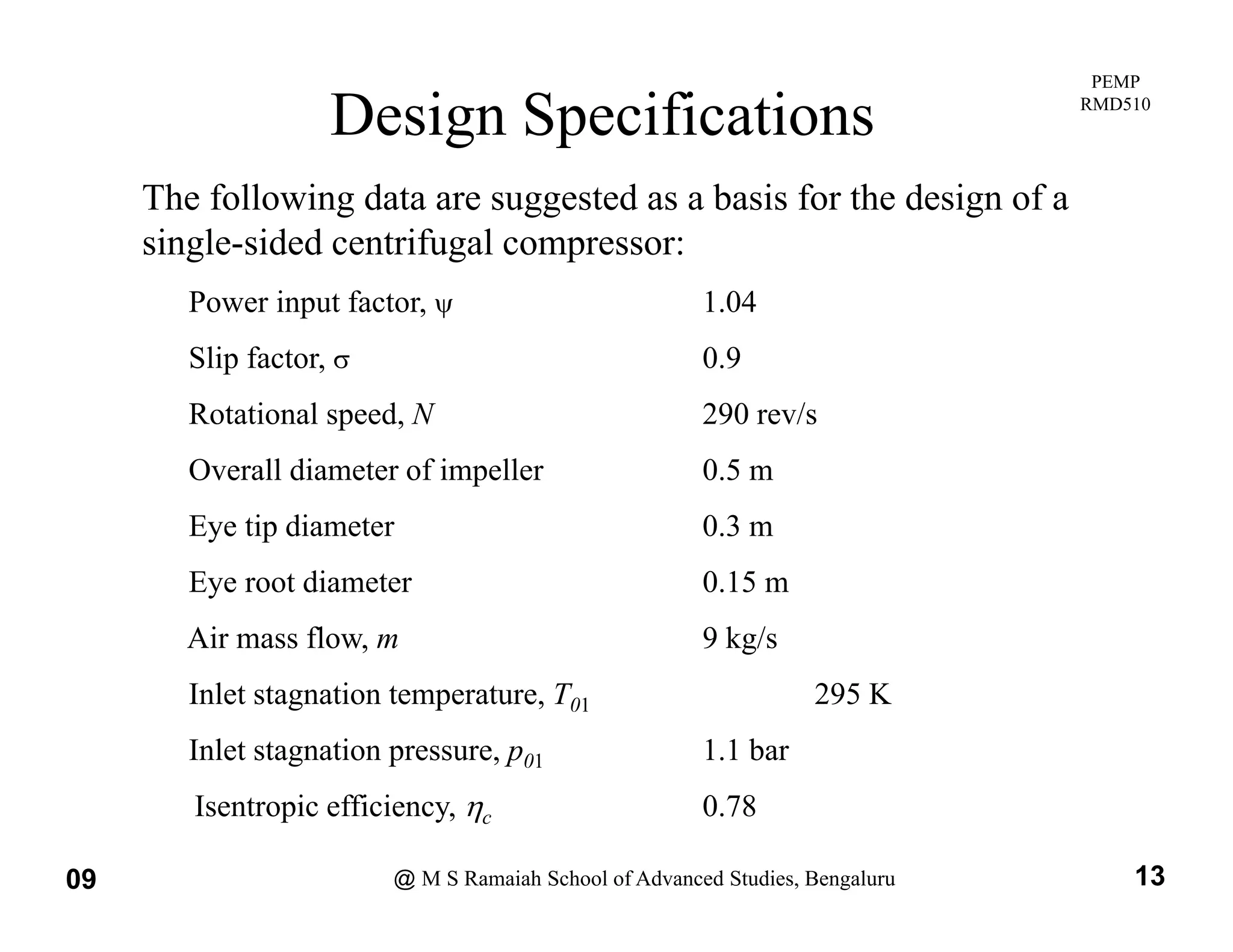
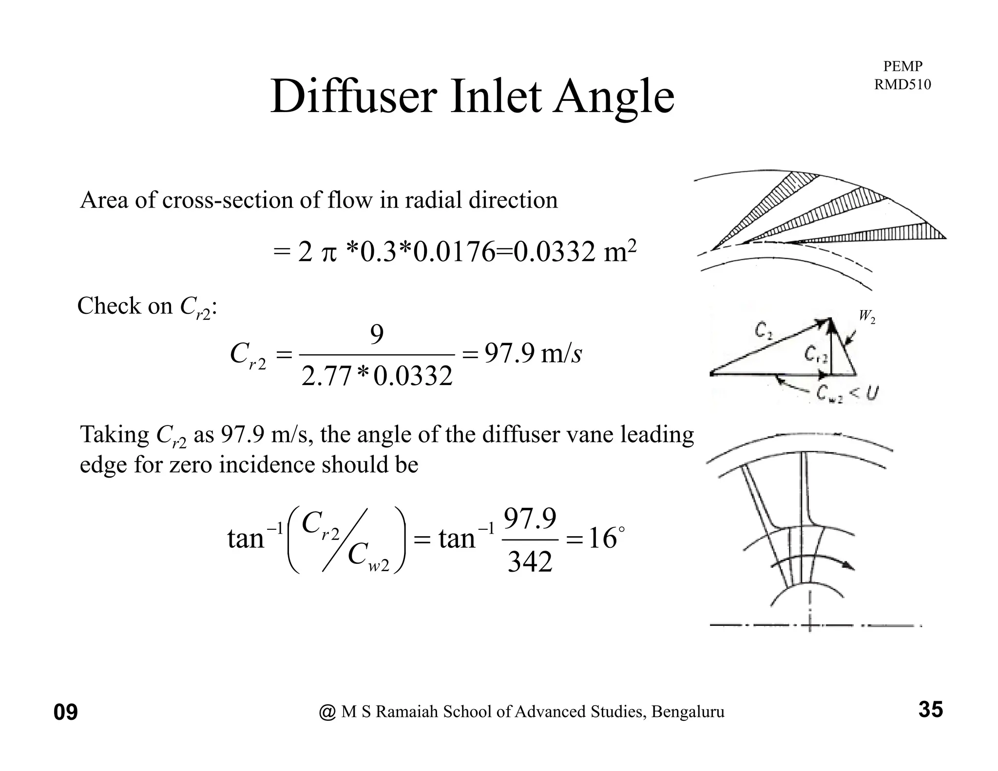
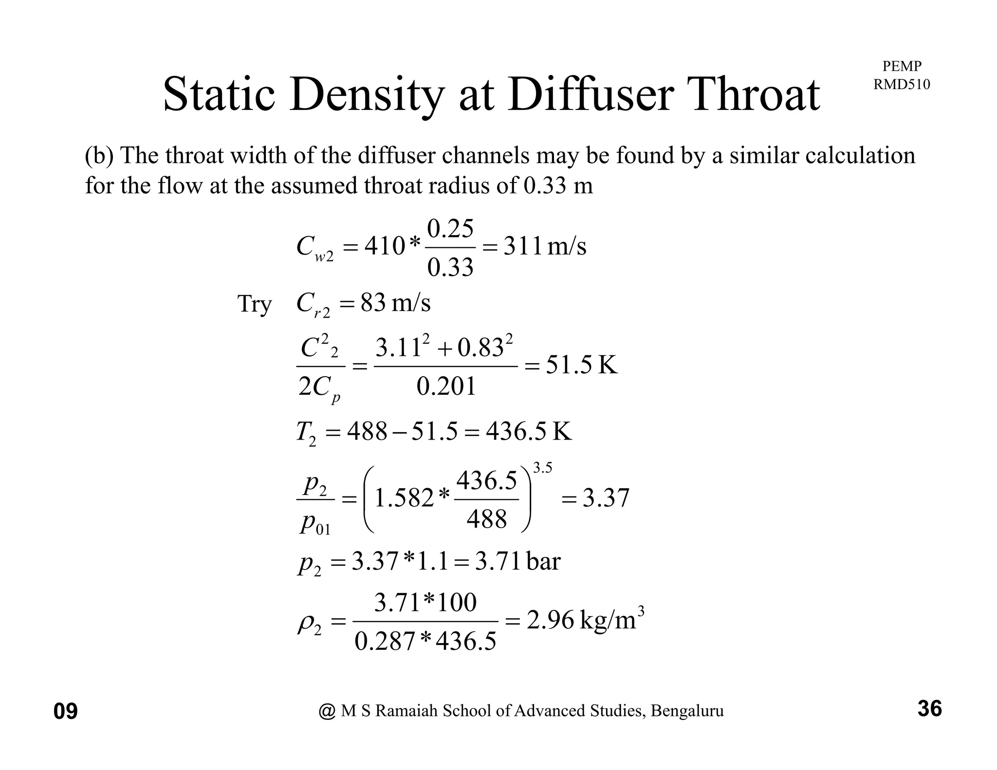
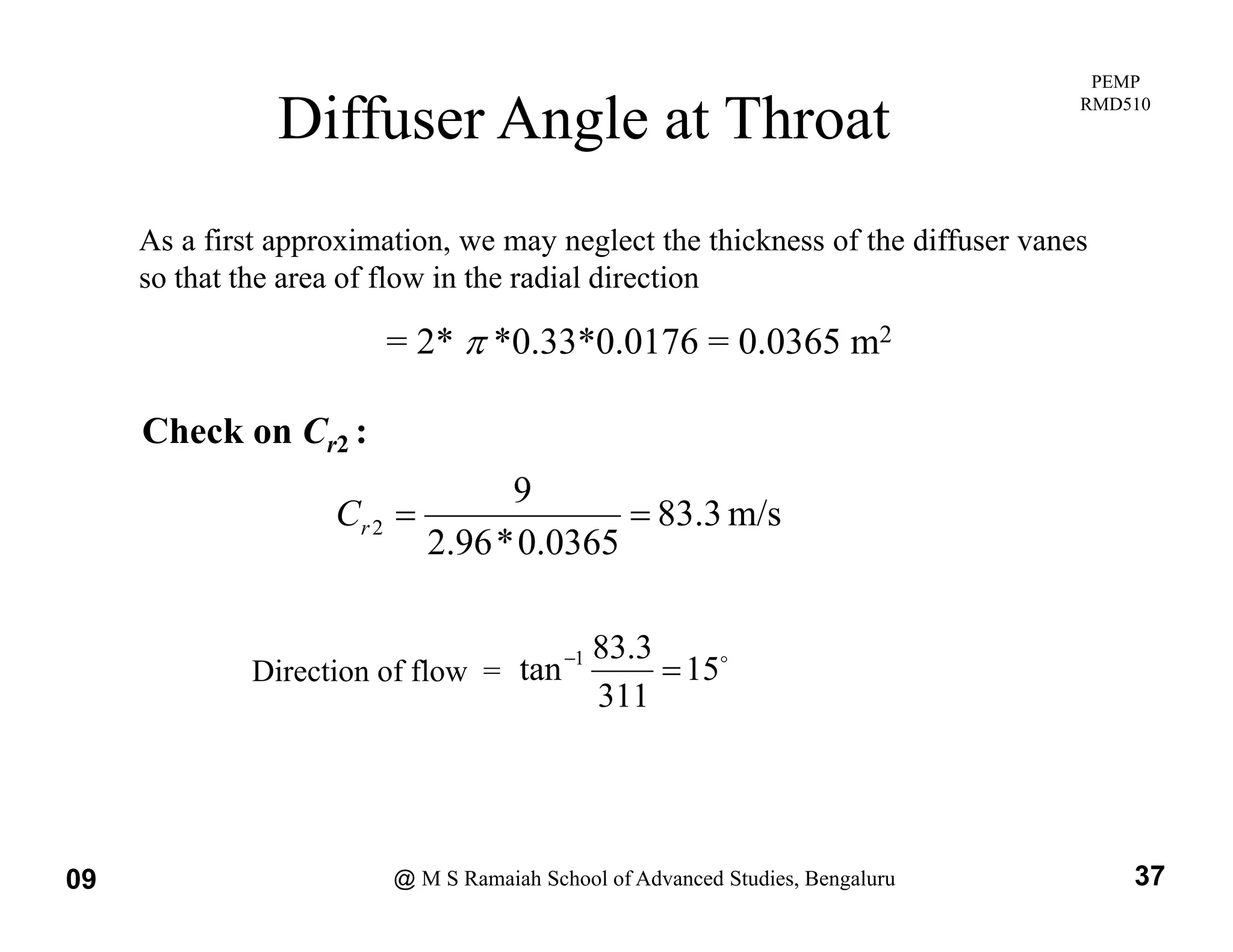
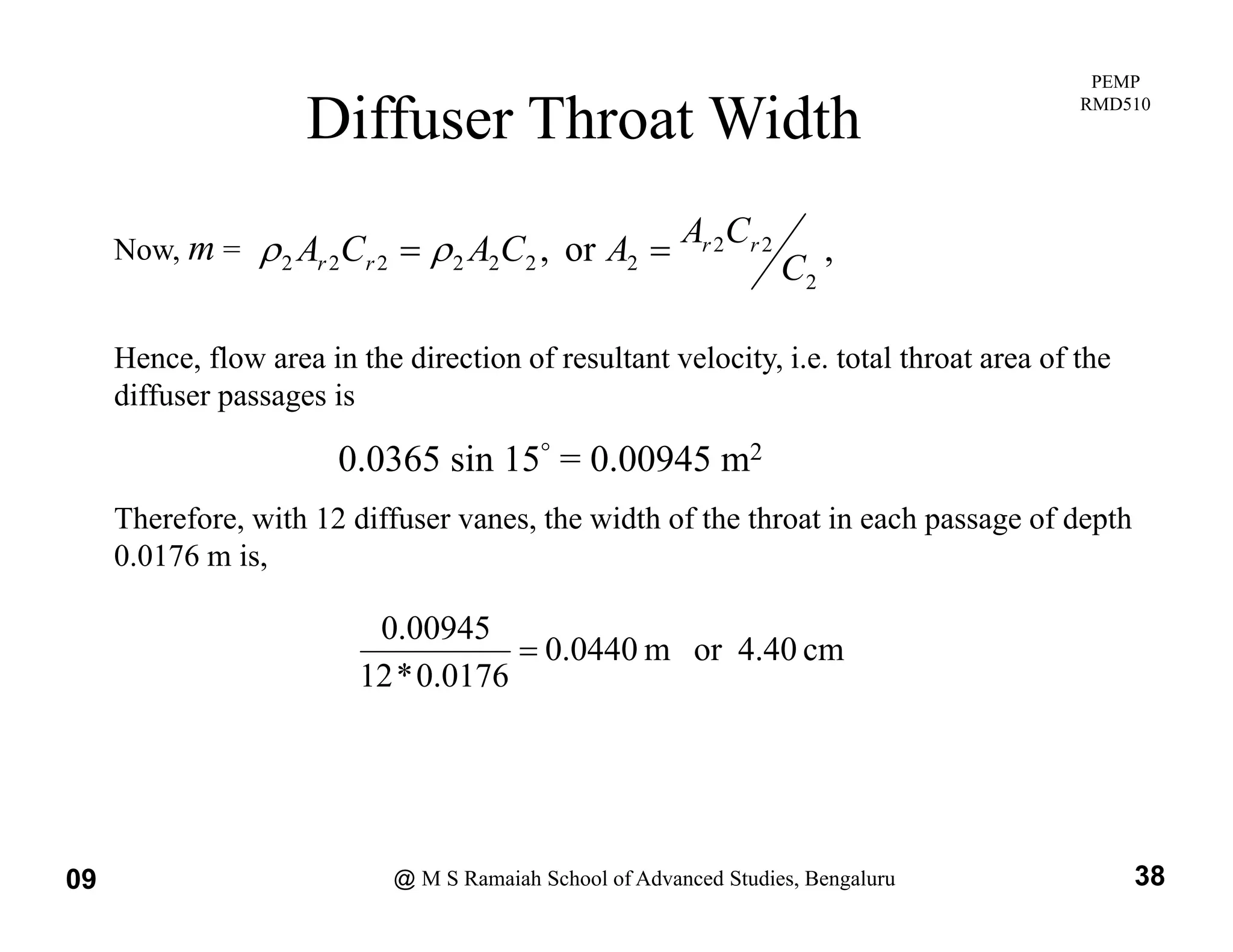
Introduction to Artificial Intelligence and History of AI
centrifugal-Compressor-stage-design for impeller, diffuser and volute
1. PEMP
RMD510
Design of Centrifugal Compressor-1
Session delivered by:
Prof Q H Nagpurwala
Prof Q H Nagpurwala
Prof. Q. H. Nagpurwala
09 @ M S Ramaiah School of Advanced Studies, Bengaluru 1
2. PEMP
RMD510
Session Objectives
To introduce the delegates to
g
• the procedure for aerodynamic design of centrifugal
compressors
• the methods for obtaining impeller geometry
• the procedure for the design of vaned and vaneless diffusers
the procedure for the design of vaned and vaneless diffusers
• Effect of geometric parameters on centrifugal compressor
performance
p
09 @ M S Ramaiah School of Advanced Studies, Bengaluru 2
3. PEMP
RMD510
Nomenclature
C Absol te elocit
C Absolute velocity
n Number of vanes
p pressure
N Rotational speed
N Rotational speed
r Radius
T Temperature
U Impeller speed at tip
p p p
Ue Impeller speed at mean radius of eye
V, W Relative velocity
Relative flow angle
Slip factor
Power input factor
Angular velocity
Suffixes
a, x Axial component
a Ambient
09 @ M S Ramaiah School of Advanced Studies, Bengaluru 3
r Radial component
w, Whirl component
4. PEMP
RMD510
Centrifugal Compressor
C1 = Ca1
Cw2
Ww2
09 @ M S Ramaiah School of Advanced Studies, Bengaluru 4
Centrifugal compressor stage and velocity diagrams at impeller entry and exit
5. PEMP
RMD510
Centrifugal Impeller with Vaned Diffuser
Without Splitter Blades With Splitter Blades
09 @ M S Ramaiah School of Advanced Studies, Bengaluru 5
Without Splitter Blades With Splitter Blades
6. PEMP
RMD510
Types of Impellers
C C C
Head – flow
characteristics
f i
for various
outlet blade
angles
09 @ M S Ramaiah School of Advanced Studies, Bengaluru 6
7. PEMP
RMD510
Components of Fluid Forces on Blades / Vanes
Fluid particles flowing through a rotor experience forces in axial,
radial and tangential directions
radial and tangential directions.
T i l
A i l Tangential component
Radial
Axial component
Radial
component
Shaft
09 @ M S Ramaiah School of Advanced Studies, Bengaluru 7
Shaft
8. PEMP
RMD510
Velocity Triangles
Approximate blade shapes can be obtained from velocity triangles.
C2 W2
Cw2
U
2
Cr2
W2
Outlet velocity triangle
Ue
Ca1=C1
W1
09 @ M S Ramaiah School of Advanced Studies, Bengaluru 8
Inlet Velocity Triangle
9. PEMP
RMD510
Design Formulae
From Euler turbine equation of energy exchange,
h
h
C
U
C
U
W
Specific work 01
03
1
2
2 h
h
C
U
C
U
W w
e
w
Specific work,
01
03 T
T
cp
Diffuser
p
Impeller
Vaneless
space
If the flow at inlet to the impeller is axial,
then Cw1 = 0, and
p
2
2 w
C
U
W
01
03 T
T
cp
09 @ M S Ramaiah School of Advanced Studies, Bengaluru 9
10. PEMP
RMD510
C
Design Formulae
C
,
'
2
2
w
w
C
C
Slip Factor
2
Then U
W
C’w2
impeller
radial
for
2
U
Cw
Then, U
W
Introducing power input factor,
2
U
W
Cw2
Cws
and temperature rise
U
W
U
T
T
2
Velocity triangle at
impeller exit
C
C
p
c
T
T 01
03
1
01
03
1
'
03
03
1
T
T
T
p c
w
C
C
01
01
03
01
03
01
03
1
T
T
p
p c
1
2
U
09 @ M S Ramaiah School of Advanced Studies, Bengaluru 10
01
1
T
c
U
p
c
11. PEMP
RMD510
Compression Process on h-s Diagram
The fluid is accelerated from
velocity C0 to velocity C1 and
the static pressure falls from
p0 to p1.
0 1
Since the stagnation enthalpy
is constant in steady, adiabatic
flow without shaft work then
h00 = h01
2
2 1
1
C
h
C
h
or 2
1
1
2
0
0
2
2
C
h
C
h
09 @ M S Ramaiah School of Advanced Studies, Bengaluru 11
12. PEMP
RMD510
Design Procedure
• Assume rotational speed, tip speed and air entry velocity
• Determine the pressure ratio of the compressor and the power
i d d i i i h h l i f h i i l i
required to drive it, assuming that the velocity of the air at inlet is
axial,
• Calculate the inlet angle of the impeller vanes at the root and tip
Calculate the inlet angle of the impeller vanes at the root and tip
radii of the eye assuming that the axial inlet velocity is constant
across the eye
• Estimate the number of vanes
• Estimate the axial depth of the impeller channels at the periphery of
the impeller
the impeller
• Estimate the inlet angle of the diffuser vanes, and
• the throat width of the diffuser passages which are assumed to be of
09 @ M S Ramaiah School of Advanced Studies, Bengaluru 12
• the throat width of the diffuser passages, which are assumed to be of
constant depth
13. PEMP
RMD510
Design Specifications
The following data are suggested as a basis for the design of a
single-sided centrifugal compressor:
P i t f t 1 04
Power input factor, 1.04
Slip factor, 0.9
Rotational speed N 290 rev/s
Rotational speed, N 290 rev/s
Overall diameter of impeller 0.5 m
Eye tip diameter 0.3 m
Eye root diameter 0.15 m
Air mass flow, m 9 kg/s
Inlet stagnation temperature, T01 295 K
Inlet stagnation pressure, p01 1.1 bar
09 @ M S Ramaiah School of Advanced Studies, Bengaluru 13
Isentropic efficiency, c 0.78
14. PEMP
RMD510
Design Requirements
Requirements are
(a) To determine the pressure ratio of the compressor
and the power required to drive it assuming that
the velocity of the air at inlet is axial
y
(b)To calculate the inlet angle of the impeller vanes
at the root and tip radii of the eye, assuming that
the axial inlet velocity is constant across the eye
(c) To estimate the axial depth of the impeller
channels at the periphery of the impeller
09 @ M S Ramaiah School of Advanced Studies, Bengaluru 14
15. PEMP
RMD510
Pressure Ratio and Power
(a) Impeller tip speed U = *0.5*290 = 455.5 m/s
Temperature equivalent of the work done on unit mass flow of air is
p q
193
5
.
455
*
9
.
0
*
04
.
1 2
2
K
U
T
T
193
*
78
0
193
10
*
005
.
1
5
.
3
1
3
01
03
T
T
K
c
T
T
p
23
.
4
295
193
*
78
.
0
1
1
1
01
01
03
01
03
T
T
T
p
p c
Power required = m cp( T03-T01) = 9*1.005*193 = 1746 kW
09 @ M S Ramaiah School of Advanced Studies, Bengaluru 15
16. PEMP
RMD510
Static Density at Inlet
(b) To find the inlet angle of the vanes it is necessary to determine the inlet
velocity, which in this case is axial, i.e. Ca1= C1.
Ca1 must satisfy the continuity equation m = 1 A1Ca1, where A1 is the flow
Ca1 must satisfy the continuity equation m 1 A1Ca1, where A1 is the flow
area at inlet.
Since the density 1 depends upon C1 and both are unknown, a trial and error
process is required
process is required.
09 @ M S Ramaiah School of Advanced Studies, Bengaluru 16
17. PEMP
RMD510
Design Procedure
• The iterative procedure is not critically dependent on the initial value
assumed for the axial velocity, but clearly it is desirable to have some rational
basis for obtaining an estimated value for starting the iteration.
• The simplest way of obtaining a reasonable estimate of the axial velocity is to
calculate the density on the basis of the known stagnation temperature and
pressure; in practice this will give a density that is too high and a velocity
that is too low.
• Having obtained an initial estimate of the axial velocity. The density can be
recalculated and hence the actual velocity from the continuity equation; if
the assumed and calculated velocities do not agree it is necessary to iterate
until agreement is reached.
• Note that it is normal to design for an axial velocity of about 150 m/s thus
• Note that it is normal to design for an axial velocity of about 150 m/s, thus
providing a suitable compromise between high flow per unit frontal area and
low frictional losses in the intake.
09 @ M S Ramaiah School of Advanced Studies, Bengaluru 17
18. PEMP
RMD510
2
2
)
15
0
3
0
(
Iteration on Ca1
m
kg
RT
p
/
30
.
1
295
*
287
0
100
*
1
.
1 3
01
1
Based on stagnation
diti
Annulus area of impeller eye, A1 =
2
2
2
053
.
0
4
)
15
.
0
3
.
0
(
m
s
m
A
m
C
RT
a /
131
053
.
0
*
30
.
1
9
295
287
.
0
1
1
1
01
conditions
C
K
c
C
p
5
.
8
201
.
0
31
.
1
10
*
005
.
1
*
2
131
2
1
2
2
3
2
1
2
Since C1= Ca1, the equivalent
dynamic temperature is
bar
T
T
p
p
K
c
C
T
T
p
992
.
0
5
.
286
295
1
.
1
5
.
286
5
.
8
295
2
5
.
3
1
1
01
01
1
1
01
1
m
kg
RT
p
/
21
.
1
5
.
286
*
287
.
0
100
*
992
.
0 3
1
1
1
1
01
09 @ M S Ramaiah School of Advanced Studies, Bengaluru 18
s
m
A
m
Ca /
140
053
.
0
*
21
.
1
9
1
1
1
Check on Ca1
19. PEMP
RMD510
Fi l t i l
Iteration on Ca1 (… contd.)
Final trial:
Try Ca1= C1=145 m/s
E i l t d i t t i
K
5
.
10
201
.
0
45
.
1
10
*
005
.
1
*
2
145
2
2
3
2
2
1
c
C
p
Equivalent dynamic temperature is
b
968
0
1
.
1
K
5
.
284
5
.
10
295
2
01
2
1
01
1
p
c
C
T
T
p
kg/m
185
.
1
5
.
284
*
287
.
0
100
*
968
.
0
bar
968
.
0
5
.
284
295
3
1
1
5
.
3
1
1
01
01
1
RT
m
T
T
p
p
m/s
143
053
0
*
185
1
9
5
.
284
287
.
0
1
1
A
m
C
RT
a
Check on Ca1:
09 @ M S Ramaiah School of Advanced Studies, Bengaluru 19
053
.
0
185
.
1
1
1 A
20. PEMP
RMD510
Flow Angles at Inducer
This is a good agreement and a further trial using Ca1= 143 m/s is
unnecessary because a small change in Ca1 has little effect upon
F hi i i h fi l l 143
. For this reason it is more accurate to use the final value 143
m/s, rather than the mean of 145 m/s (the trial value) and 143
m/s. The vane angles can now be calculated as follows:
Peripheral speed at the impeller eye tip radius
= * 0 3 * 290 = 273 m/s
0.3 290 273 m/s
and at eye root radius = 136.5 m/s
143
33
46
5
136
143
tan 1
.
.
65
27
273
143
tan 1
.
at root =
at tip =
09 @ M S Ramaiah School of Advanced Studies, Bengaluru 20
65
27
273
tan .
at tip
21. PEMP
RMD510
Radial Velocity and Static Density at Exit
(c) To calculate the required depth of the impeller channel at the
periphery we must make some assumptions regarding both
h di l f l i h i d h di i i f
the radial component of velocity at the tip and the division of
losses between the impeller and the diffuser so that the
density can be evaluated. The radial component of velocity
y p y
will be relatively small and can be chosen by the designer; a
suitable value is obtained by making it approximately equal to
the axial velocity at inlet to the eye
the axial velocity at inlet to the eye.
To estimate the density at the impeller tip, the static pressure
and temperature are found by calculating the absolute velocity
p y g y
at this point and using it in conjunction with the stagnation
pressure which is calculated from the assumed loss up to this
point
09 @ M S Ramaiah School of Advanced Studies, Bengaluru 21
point.
22. PEMP
RMD510
Absolute Velocity at Exit
Making the choice Cr2 = Ca1, we have Cr2 = 143 m/s
Cw2 = U = 0.9*455.5 = 410 m/s
K
8
.
93
201
.
0
10
.
4
43
.
1
2
2
2
2
2
2
2
2
2
2
p
w
r
p c
C
C
c
C
09 @ M S Ramaiah School of Advanced Studies, Bengaluru 22
23. PEMP
RMD510
Distribution of Total Loss
Assuming that half the total loss, i.e. 0.5(1- c) = 0.11, occurs in
the impeller, the effective efficiency of compression from p01 to p02
ill b 0 89 th t
5
.
3
5
.
3
02
582
.
1
193
*
89
.
0
1
p
will be 0.89 so that,
01 295
p
Now, (p2 /p02) = (T2 /T02)3.5
K
2
394
8
93
488
2
2
C
T
T
2 02 2 02
and T02 = T03 = 193+295 = 488 K
th t
5
.
3
2 2
.
394
p
K
2
.
394
8
.
93
488
2
2
02
2
p
c
T
T
so that
09 @ M S Ramaiah School of Advanced Studies, Bengaluru 23
02
2
488
p
24. PEMP
RMD510
Impeller Width at Exit
Since (p2 /p01) = (p2 /p02) (p02 /p01)
5
.
3
01
2
35
.
2
488
2
.
394
*
582
.
1
p
p
3
2
2
2
01
kg/m
28
.
2
2
394
*
287
0
100
*
58
.
2
58
.
2
1
.
1
*
35
.
2
488
RT
p
bar
p
p
2
2 g
2
.
394
*
287
.
0
RT
The required flow area normal to the radial direction at the impeller tip is
2
9
m 2
2
2
m
0276
.
0
143
*
28
.
2
9
r
C
m
A
Hence the depth of impeller channel at exit
5
.
0
*
0276
.
0
b = 0.0176 m or 1.76 cm
09 @ M S Ramaiah School of Advanced Studies, Bengaluru 24
(This result will be used when discussing the design of the
diffuser in the next section)
25. PEMP
RMD510
Estimation of Number of Blades
The number of impeller vanes can be obtained from the correlations for slip factor
Stanitz correlation Wiesner correlation
7
.
0
2
cos
1
Z
s
Stodola correlation
and ’2 is measured from radial direction.
2
In the present case, ’2 = 0
Hence, Stanitz correlation reduces to
Z
s
63
.
0
1
09 @ M S Ramaiah School of Advanced Studies, Bengaluru 25
Z
For s = 0.9, number of blades, Z = 19.79 ~ 20
26. PEMP
RMD510
Generation of Blade Profile
Impeller vane profiles can be generated
• by using softwares, like BLADEGEN
Profile A
• by trial and error process, using CAD and CFD tools
Profile A
Profile B
Final Profile D
09 @ M S Ramaiah School of Advanced Studies, Bengaluru 26
Profile C
27. PEMP
RMD510
Types of Diffusers
• Vaneless diffuser
C i l diff
Angular momentum is conserved in the vaneless
space; i.e. r.Cw = constant. Cr also varies in the
vaneless space because of the change in radius.
H ti ti f C d C ill i ld th
• Conical diffuser Hence, estimation of Cw and Cr will yield the
absolute velocity and flow angle at inlet to the
vaned /conical diffuser.
09 @ M S Ramaiah School of Advanced Studies, Bengaluru 27
28. PEMP
RMD510
Types of Diffusers
Uniform thickness
curved vanes
Aerofoil shape
vanes
Uniform thickness
Wedge shape
vanes
straight vanes
09 @ M S Ramaiah School of Advanced Studies, Bengaluru 28
29. PEMP
RMD510
Types of Diffusers
• Straight wedge type
• Aerofoil shaped vanes
(a) Straight wedge type (b) Aerofoil shaped vanes
09 @ M S Ramaiah School of Advanced Studies, Bengaluru 29
30. PEMP
RMD510
Types of Impellers and Diffusers
Impellers
• Radially ending
• Backswept
Diffusers
• Backswept
• Pre-swirl
• Above w/splitter blades
• Vaneless
• Vaned
Above w/splitter blades
– Radial
– Wedge
Di t
• Discrete-passage
09 @ M S Ramaiah School of Advanced Studies, Bengaluru 30
NASA Glenn Research Center
32. PEMP
RMD510
Diffuser Design
Radial width of vane less space = 5 cm
Approximate mean radius of diffuser throat = 0.33 m
Depth of diffuser passages = 1.76 cm
Number of diffuser vanes = 12
I i i d d i
It is required to determine:
(a) the inlet angle of the diffuser vanes, and
(b) the throat width of the diffuser passages which are assumed to be of
(b) the throat width of the diffuser passages, which are assumed to be of
constant depth.
For simplicity, it will be assumed that the additional friction loss in the short
distance between impeller tip and diffuser throat is small and therefore the 50 %
of the overall loss can be considered to have occurred up to the diffuser throat.
For convenience, suffix 2 will be used to denote any plane in the flow after the
impeller tip the conte t making it clear hich plane is nder consideration
09 @ M S Ramaiah School of Advanced Studies, Bengaluru 32
impeller tip, the context making it clear which plane is under consideration.
33. PEMP
RMD510
( ) C id diti t th di f th diff l di d i t
Iteration on Cr2 at Diffuser Inlet
(a) Consider conditions at the radius of the diffuser vane leading edge, i.e. at
r2 = 0.25+0.05 = 0.3m. Since in the vaneless space Cwr = constant for
constant angular momentum,
25
.
0
The radial component of velocity can be found by trial and error. The
iteration may be started by assuming that the temperature equivalent of the
s
m
Cw /
342
30
.
0
25
.
0
*
410
2
y y g p q
resultant velocity is that corresponding to the whirl velocity, but only the
final trial is given here.
Try C = 97 m/s
Try Cr2 = 97 m/s
K
9
.
62
201
.
0
97
.
0
42
.
3
2
2
2
2
2
p
c
C
Ignoring any additional loss between the impeller tip and the diffuser vane
leading edges at 0.3m radius, the stagnation pressure will be that
calculated for the impeller tip, i.e.
p
09 @ M S Ramaiah School of Advanced Studies, Bengaluru 33
5
.
3
01
02 582
.
1
p
p
34. PEMP
RMD510
Static Density at Diffuser Inlet
Proceeding as before we have
K
1
425
9
62
488
T
5
.
3
2
2
488
1
.
425
K
1
.
425
9
.
62
488
p
p
T
5
.
3
2
02
07
.
3
488
1
.
425
*
582
.
1
488
p
p
p
2
01
100
*
38
3
bar
38
.
3
1
.
1
*
07
.
3
488
p
p
3
2 kg/m
77
.
2
1
.
425
*
287
.
0
100
*
38
.
3
09 @ M S Ramaiah School of Advanced Studies, Bengaluru 34
35. PEMP
RMD510
Diffuser Inlet Angle
Area of cross-section of flow in radial direction
2
9
= 2 *0.3*0.0176=0.0332 m2
Check on Cr2: W2
Taking C as 97 9 m/s the angle of the diffuser vane leading
s
Cr m/
9
.
97
0332
.
0
*
77
.
2
9
2
Taking Cr2 as 97.9 m/s, the angle of the diffuser vane leading
edge for zero incidence should be
16
9
.
97
t
t 1
2
1
C
16
342
tan
tan 1
2
2
1
w
r
C
C
09 @ M S Ramaiah School of Advanced Studies, Bengaluru 35
36. PEMP
RMD510
Static Density at Diffuser Throat
(b) The throat width of the diffuser channels may be found by a similar calculation
for the flow at the assumed throat radius of 0.33 m
/
311
25
.
0
*
410
C
2
2
2
2
2
m/s
83
m/s
311
33
.
0
*
410
C
C
r
w
Try
2
2
2
2
K
5
436
5
51
488
K
5
.
51
201
.
0
83
.
0
11
.
3
2
T
C
C
p
5
.
3
01
2
2
37
.
3
488
5
.
436
*
582
.
1
K
5
.
436
5
.
51
488
p
p
T
3
2
2
01
kg/m
96
.
2
100
*
71
.
3
bar
71
.
3
1
.
1
*
37
.
3
p
p
09 @ M S Ramaiah School of Advanced Studies, Bengaluru 36
2 kg/m
96
.
2
5
.
436
*
287
.
0
37. PEMP
RMD510
Diffuser Angle at Throat
As a first approximation, we may neglect the thickness of the diffuser vanes
so that the area of flow in the radial direction
= 2* *0.33*0.0176 = 0.0365 m2
m/s
3
.
83
0365
0
*
96
2
9
2
r
C
Check on Cr2 :
0365
.
0
*
96
.
2
3
.
83
1
15
311
3
.
83
tan 1
Direction of flow =
09 @ M S Ramaiah School of Advanced Studies, Bengaluru 37
38. PEMP
RMD510
Diffuser Throat Width
,
or
,
2
2
2
2
2
2
2
2
2
2 C
C
A
A
C
A
C
A r
r
r
r
Now, m =
Hence, flow area in the direction of resultant velocity, i.e. total throat area of the
diffuser passages is
0.0365 sin 15° = 0.00945 m2
Therefore, with 12 diffuser vanes, the width of the throat in each passage of depth
0.0176 m is,
cm
4 40
or
m
0440
0
00945
.
0
cm
4.40
or
m
0440
.
0
0176
.
0
*
12
09 @ M S Ramaiah School of Advanced Studies, Bengaluru 38
39. PEMP
RMD510
Inducer Relative Mach Number on Ground
Consider inlet Mach number at the tip radius of the impeller eye
Inlet velocity = 143 m/s (axial)
Eye tip speed = 273 m/s
Relative velocity at tip =
Velocity of sound =
m/s
308
273
143 2
2
m/s
338
10
*
5
284
*
287
0
*
4
1 3
Velocity of sound =
Maximum Mach number at inlet = 308/338 = 0.91
m/s
338
10
*
5
.
284
*
287
.
0
*
4
.
1 3
This would not be considered satisfactory even if it were actually the maximum
value likely to be reached. But, if the compressor is part of an aircraft engine
required to operate at an altitude of 11000 m, where the atmospheric temperature
09 @ M S Ramaiah School of Advanced Studies, Bengaluru 39
q p , p p
is only about 217 K, we must calculate the Mach number under these conditions.
40. PEMP
RMD510
Si th ill b t t i d t th ff t i th i t k h th
Inducer Relative Mach Number in Flight
Since there will be a temperature rise due to the ram effect in the intake when the
aircraft has a forward speed, the effect of drop in atmospheric temperature will
not be quite so great as might be expected. We will take 90 m/s (324 km/hr) as
being the minimum speed likely to be reached at high altitude
being the minimum speed likely to be reached at high altitude.
Temperature equivalent of forward speed = 4K
Inlet stagnation temperature = 217 + 4 = 221 K
Inlet stagnation temperature 217 4 221 K
Temperature equivalent of axial inlet
velocity from the first example = 10.5 K
Inlet static temperature at altitude = 210.5 K
5
284 2
1
Inlet Mach number at altitude = 06
.
1
5
.
210
5
.
284
91
.
0
2
09 @ M S Ramaiah School of Advanced Studies, Bengaluru 40
This is clearly too high and we will find the Mach number when an inlet prewhirl
of 30° is introduced.
41. PEMP
RMD510
Effect of Inlet Prewhirl
I thi th b l t i l t l it ill b li htl hi h th b f th t th i l t
Try C =150 m/s
In this case the absolute inlet velocity will be slightly higher than before, so that the inlet
static temperature will be slightly lower. A new value for the axial velocity must be found
by the usual trial and error process. Reverting to the original sea-level static case:
Try Ca1 =150 m/s
C1 = 150/cos 30 = 173.2 m/s
Temperature equivalent of C1 = 14.9 K
T1 = 295-14.9 = 280.1K
p1 = 0.918 bar and
9
3
1 /
14
.
1 m
kg
Check on Ca1 =
Whirl velocity at inlet, Cw1 = 149 tan 30
= 86 m/s
s
m /
149
053
.
0
*
14
.
1
9
30º
= 86 m/s
Maximum relative velocity =
= 239 m/s
239
2
2
86
273
149
09 @ M S Ramaiah School of Advanced Studies, Bengaluru 41
Hence maximum inlet Mach number at T01= 295 K is
71
.
0
10
*
1
.
280
*
287
.
0
*
4
.
1
239
3
42. PEMP
RMD510
U d ltit d diti thi ld i t littl th 0 8 H
Effect of Prewhirl on Pressure Ratio
Under altitude conditions this would rise to little more than 0.8. Hence, a
prewhirl of 30° can be regarded as adequate.
To show the effect of 30° prewhirl on the pressure ratio, we will take the
worst case and assume that the prewhirl is constant over the eye of the
impeller.
Speed of impeller eye at mean radius, m/s
8
.
204
2
5
.
136
237
e
U
2
e
1
2
e
w
p
U
C
U
c
Actual temperature rise
K
175
10
*
005
.
1
8
.
204
*
86
5
.
455
*
9
.
0
04
.
1
3
2
175
*
78
0
5
.
3
03
p
79
.
3
295
175
78
.
0
1
01
03
p
p
This pressure ratio may be compared with the original value of 4.23 obtained
ith no pre hirl It is sometimes ad antageo s to se adj stable inlet g ide
09 @ M S Ramaiah School of Advanced Studies, Bengaluru 42
with no prewhirl. It is sometimes advantageous to use adjustable inlet guide
vanes to improve the performance under off-design conditions.
43. PEMP
RMD510
Mach Number at Impeller Exit
We next consider the relevant Mach numbers in the diffuser. The maximum
value will occur at the entry to the diffuser, that is, at the impeller tip. Once
again the values calculated in the previous example will be used.
The temperature equivalent of the resultant velocity of the air leaving the
impeller was found to be
2
K
C
C
p
8
.
93
2
2
2
and hence
C2 = 434m/s
T f d b 394 2 K d h h M h b h i ll i l
T2 was found to be 394.2 K and thus the Mach number at the impeller tip equals
09
.
1
10
*
2
394
*
287
0
*
4
1
434
3
09 @ M S Ramaiah School of Advanced Studies, Bengaluru 43
10
*
2
.
394
*
287
.
0
*
4
.
1
44. PEMP
RMD510
Mach Number at Diffuser Inlet
Now consider the leading edge of the diffuser vanes. The whirl velocity was
found to be 342 m/s and the radial component 97.9 m/s. The resultant velocity
at this radius is therefore 356 m/s. The static temperatures was 425.1 K at this
radius so that the Mach number is
86
.
0
10
*
1
.
425
*
287
.
0
*
4
.
1
356
3
0
.
5
87
.
0
.
In the particular design under consideration, the Mach number is 1.09 at the
impeller tip and 0.86 at the leading edges of the diffuser vanes. It has been
f d h l h di l l i i b i h b
found that as long as the radial velocity component is subsonic, Mach numbers
greater than unity can be used at the impeller tip without loss of efficiency. It
appears that supersonic diffusion can occur without the formation of shock
waves if it is carried out at constant angular momentum with vortex motion in
the vaneless space. But the Mach number at the leading edge of the diffuser
vanes is rather high and it would probably be advisable to increase the radial
width of the vaneless space or the depth of the diffuser to reduce the velocity at
09 @ M S Ramaiah School of Advanced Studies, Bengaluru 44
width of the vaneless space or the depth of the diffuser to reduce the velocity at
this radius.
45. PEMP
RMD510
Comments
High Mach numbers at the leading edges of the diffuser vanes are undesirable, not
only because of the danger of the shock losses, but because they imply high air speeds
and relatively large pressures at the stagnation points where the air is brought to rest
locally at the leading edges of the vanes. This causes a circumferential variation in
static pressure, which is transmitted upstream in a radial direction through the
vaneless space to excite the impeller tip. Although the variation would considerably
reduce by the time it reaches the impeller it may well be large enough to excite the
reduce by the time it reaches the impeller, it may well be large enough to excite the
impeller vanes and cause mechanical failure due to vibrational fatigue cracks in the
vanes. This will occur when the exciting frequency, which depends on the rotational
speed and relative number of impeller and diffuser vanes, is of the same order as one of
the natural frequencies of the impeller vanes. To reduce the likelihood of this, care is
taken to see that the number of vanes in the impeller is not an exact multiple of the
number in the diffuser; it is common practice to use a prime number for the impeller
vanes and an even number for the diffuser vanes.
The reason for the vaneless space will now be apparent: the dangers of both, shock
losses and excessive circumferential variation in static pressure, would be considerably
increased if the leading edges of the diffuser vanes were too near the impeller tip where
09 @ M S Ramaiah School of Advanced Studies, Bengaluru 45
g g p p
the Mach numbers are very high.
46. PEMP
RMD510
Wi h h di i
Further Work
With these dimensions
1. Create a geometric model of the Centrifugal compressor
using a CAD tool
using a CAD tool.
2. Export the model to a CFD tool and carry out the fluid
flow analysis
flow analysis
3. Using an FEM tool, carry out the structural dynamic
analysis choosing appropriate material properties.
4. Create a shaft and choose bearings and carryout rotor
dynamic analysis
y y
5. Generate manufacturing drawings
6 Generate compressor operating characteristics using a
09 @ M S Ramaiah School of Advanced Studies, Bengaluru 46
6. Generate compressor operating characteristics using a
suitable post processor.
47. PEMP
RMD510
Design Guidelines
Relative velocity ratio, W2/Wsh1 > 0.75 de Haller number
Exit absolute flow angle, 2 = 60º - 65º
Sweep angle for backward swept impeller = 30º
Ratio of inducer tip diameter to
impeller outer diameter, dsh1/ d2 = 0.4 - 0.55 cos
p , sh1 2
Number of impeller blades by Wiesner’s correlation,
Inducer hub-tip diameter ratio = 0.5 – 0.6
7
.
0
2
cos
1
Z
s
09 @ M S Ramaiah School of Advanced Studies, Bengaluru 47
48. PEMP
RMD510
Effect of Geometric Parameters
Performance of the centrifugal compressor is affected
by the following geometric parameters:
• Impeller vane thickness
• Splitter blades
Splitter blades
• Trailing end skew
• Exit trim
• Exit trim
• Inducer leading edge sweep
• Vaned shroud at inducer
• Impeller with integral shroud
09 @ M S Ramaiah School of Advanced Studies, Bengaluru 48
• Inlet guide vanes
49. PEMP
RMD510
Impeller Vane Thickness
Because of manufacturing problems and physical necessity, impeller vanes have
definite thickness. When fluid leaves the impeller, the vanes no longer contain
the flow, and the meridional velocity decreases. Hence, both the relative and
absolute velocities also decrease with consequent change in exit flow angle.
C
09 @ M S Ramaiah School of Advanced Studies, Bengaluru 49
50. PEMP
RMD510
Splitter Blades
Compressor specifications
(a) (b)
Inducer hub dia. 22 mm
Inducer tip dia. 65 mm
Impeller tip dia 87 mm
Compressor specifications
Impeller tip dia. 87 mm
Number of vanes 18
Rotational speed 81000 rpm
Inlet pressure 0.98 bar
( )
Inlet temperature 303 K
(a) LR- 0.81 (b) LR-0.65 (c) LR-0.50 (d) LR-0.35
(c)
(d)
09 @ M S Ramaiah School of Advanced Studies, Bengaluru 50
Geometric models of impellers with different splitter to main
blade length ratios (LR=0.81, 0.65, 0.50 and 0.35)
51. PEMP
RMD510
Splitter Blades
The optimum length of
splitter blade is half the length
p g
of the main blade.
Maximum efficiency and
pressure ratio at 0.50 splitter
length.
i ifi i
No significant improvement
in performance when splitter
length is reduced further.
09 @ M S Ramaiah School of Advanced Studies, Bengaluru 51
g
52. PEMP
RMD510
Trailing End Skew
Hub Hub Hub
45° 90°
45°
45 - 45°
09 @ M S Ramaiah School of Advanced Studies, Bengaluru 52
45° Skew 0° Skew -45° Skew
53. PEMP
RMD510
Trailing End Skew
O ti S d 30 000
0.95
Operating Speed 30,000 rpm
3.50
4.00
4.50
Pressure
Ratio
2/P01)
Operating Speed 30,000 rpm
0.85
0.90
ic
Efficiency
1.4%
2.00
2.50
3.00
Total
to
Total
(P02
45° 30°
0° -30°
-45°
0.70
0.75
0.80
Isoentrop
45° 30°
0° -30°
-45°
00
0.50 1.00 1.50 2.00 2.50
Corrected Mass flow rate (Kg/s)
0.70
1.00 1.50 2.00 2.50
Corrected Mass flow rate (Kg/s)
Effect of exit skew on impeller performance
09 @ M S Ramaiah School of Advanced Studies, Bengaluru 53
54. PEMP
RMD510
5
Leading End Skew
3 5
4
4.5
5
sure
ratio
Baseline
Back sweep 10˚
Back sweep 15˚
Stall margin has increased with
20º forward sweep
2
2.5
3
3.5
Total
press
Back sweep 20˚
Back sweep 25˚
Forward sweep 10˚
Forward sweep 20˚
2
3 3.5 4 4.5 5 5.5 6 6.5 7
Corrected mass flow rate (kg/s)
5
4
re
ratio
Baseline(0.5 mm tip clc.)
Forward sweep 20˚(0.5 mm tip clc.)
3
Total
pressur
Forward sweep 20˚(0.75 mm tip clc.)
Definition of leading end sweep
A higher tip clearance with forward
d f b t th
09 @ M S Ramaiah School of Advanced Studies, Bengaluru 54
2
3 4 5 6 7
Corrected mass flow rate (kg/s)
sweep may reduce performance but the
compressor production cost will be low
55. PEMP
RMD510
Vaned Shroud at Inducer
Inducer leading
09 @ M S Ramaiah School of Advanced Studies, Bengaluru 55
Inducer leading
end sweep Barton M.T. et al: ASME J. of Turbomachinery,
Vol. 128, October 2006, pp 627-631
56. PEMP
RMD510
Vaned Shroud at Inducer
09 @ M S Ramaiah School of Advanced Studies, Bengaluru 56
Barton M.T. et al: ASME J. of Turbomachinery,
Vol. 128, October 2006, pp 627-631
57. PEMP
RMD510
Exit Trim
Radial exit
Altering the axial width of the
i ll t it k
Exit width trim
impeller vanes at exit, known as
Exit Trim, with respect to the
baseline design, helps the manu-
facturer in producing design
variants to meet different
customer requirements without
Axial entry
customer requirements without
spending effort in carrying out an
ab initio design for a new product
ithi t i f Axial entry
within a certain range of
specifications.
09 @ M S Ramaiah School of Advanced Studies, Bengaluru 57
59. PEMP
RMD510
Inlet Guide Vanes
• Inlet Guide Vanes (IGV) provide
prewhirl to the flow entering the
impeller
impeller.
• The inlet velocity triangle is altered.
• Th k it f th
• The work capacity of the compressor
also changes due to introduction of whirl
component of velocity.
W = U2Cw2 + U1Cw1
• Introduction of IGVs is desired to
i h ff d i f f
improve the off-design performance of
the compressor and to limit the inducer
tip Mach number; but the friction losses
09 @ M S Ramaiah School of Advanced Studies, Bengaluru 59
will tend to increase.
60. PEMP
RMD510
Session Summary
This session has covered:
• Basic design methodology of centrifugal compressors.
• Calculation of aerodynamic and geometric parameters of the
y g p
impeller and generation of velocity triangles.
• Calculation of diffuser parameters, especially the diffuser inlet
angle and the throat width of diffuser passage
angle and the throat width of diffuser passage.
• Effect of geometric parameters on compressor performance.
09 @ M S Ramaiah School of Advanced Studies, Bengaluru 60