Downloaded 142 times
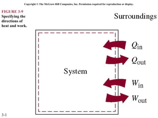
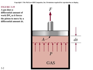
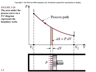
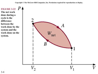
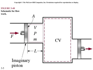
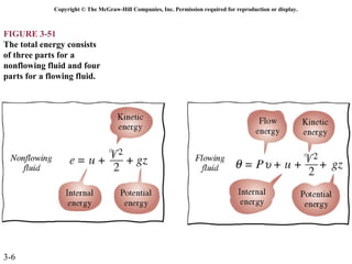
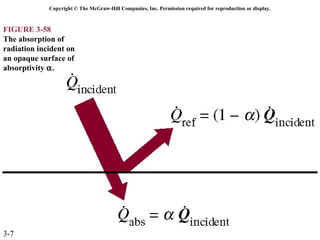

The document discusses different types of energy transfer including heat, work, and mass. It contains figures illustrating concepts like specifying the directions of heat and work, a gas doing work as it forces a piston to move, the area under a process curve in a P-V diagram representing boundary work, the difference between work done by and on a system determining net work during a cycle, schematics of flow work, parts that make up total energy for flowing and non-flowing fluids, and absorption of radiation at an opaque surface. The document focuses on concepts and processes related to different modes of energy transfer.