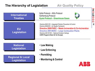
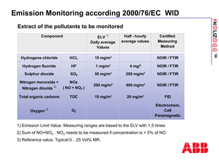
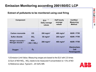
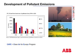
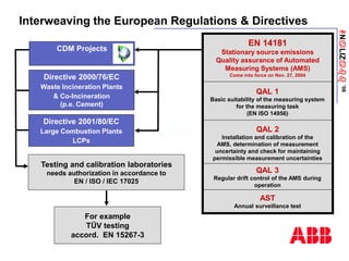
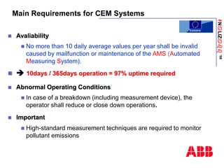
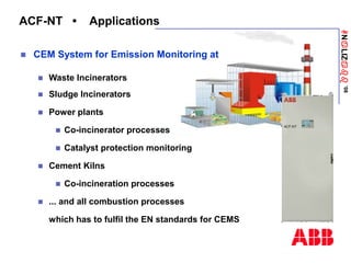
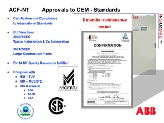
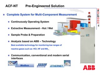
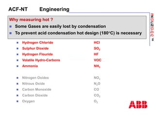
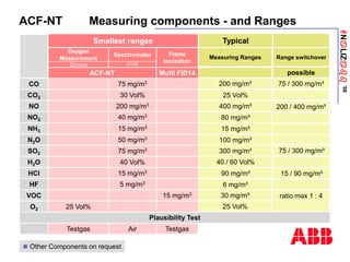
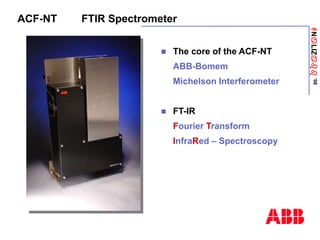
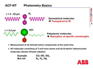
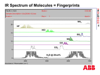
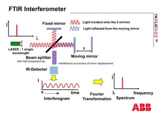
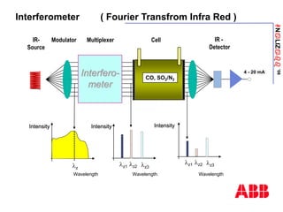
©
Copyright
2008
ABB.
All
rights
reserved.
-
1
-
11/21/2022
ACF-NT
CEM System
based on FTIR Technology
Günter Haberzettl
21-22 de Mayo
ANaLIZabb
’08
ACF-NT The leading Multi-Component CEM-System
ANaLIZabb
’08
ACF-NT Table of Contents
 Legislation
 Application
 Approvals
 Pre-engineered solution
 Spectromter
 Communication
 Remote Control
 Service
ANaLIZabb
’08
The Hierarchy of Legislation Air Quality Policy
Directive 96/61/CE - Integrated Pollution Prevention & Control
Directive 96/62/EC - Air Quality Framework
Directive 2000/76/EC – Waste Incineration & Co-Incineration
Directive 2001/80/EC – Large Combustion Plants
Directive 2001/81/EC – National Emission Ceilings
CAFE Program (Clean Air for Europe)
International
Treaties
EU
Legislation
National
Legislation
Regional & Local
Legislation
Sofia Protocol – NOx Protocol
Gothenburg Protocol
Kyoto Protocol – Greenhouse Gases
• Law Making
• Law Enforcing
• Permitting
• Monitoring & Control
ANaLIZabb
’08
Emission Monitoring according 2000/76/EC WID
ELV 1)
Daily average
Values
Half - hourly
average values
Certified
Measuring
Method
Component
Hydrogene chloride HCL 10 mg/m³ NDIR / FTIR
Hydrogen fluoride HF 1 mg/m³ 4 mg/³ NDIR / FTIR
Sulphur dioxide SO2 50 mg/m³ 200 mg/m³ NDIR / FTIR
Nitrogen monoxide +
Nitrogen dioxide 2)
NOx
( NO + NO2 )
200 mg/m³ 400 mg/m³ NDIR / FTIR
Total organic carbons TOC 10 mg/m³ 20 mg/m³ FID
Oxygen 3)
O2
Electrochem.
Cell
Paramagnetic
Extract of the pollutants to be monitored
1) Emission Limit Value. Measuring ranges are based to the ELV with 1,5 times
2) Sum of NO+NO2 . NO2 needs to be measured if concentration is > 5% of NO
3) Reference value. Typical 0…25 Vol% MR.
ANaLIZabb
’08
Emission Monitoring according 2001/80/EC LCP
Extract of pollutants to be monitored using coal firing
ELV
1)
Daily average
values
Half hourly
average
values
Certified
Measuring
Method
Component
Carbon monoxide CO 200 mg/m³ 400 mg/m³ NDIR / FTIR
Sulfur dioxide SO2 50 mg/m³ 200 mg/m³ NDIR / FTIR
NOx
( NO + NO2 )
200 mg/m³ 400 mg/m³ NDIR / FTIR
Oxygen
3)
O2
Electrochem.
Cell
Paramagnetic
Nitrigen monoxide +
Nitrogen dioxide 2)
1) Emission Limit Value. Measuring ranges are based to the ELV with 2,5 times
2) Sum of NO+NO2 . NO2 needs to be measured if concentration is > 5% of NO
3) Reference value. Typical 0…25 Vol% MR.
ANaLIZabb
’08
Development of Pollutant Emissions
CAFE = Clean Air for Europe Program
ANaLIZabb
’08
Interweaving the European Regulations & Directives
Directive 2001/80/EC
Large Combustion Plants
LCPs
For example
TÜV testing
accord. EN 15267-3
Directive 2000/76/EC
Waste Incineration Plants
& Co-Incineration
(p.e. Cement)
EN 14181
Stationary source emissions
Quality assurance of Automated
Measuring Systems (AMS)
Come into force on Nov. 27, 2004
QAL 1
Basic suitability of the measuring system
for the measuring task
(EN ISO 14956)
QAL 2
Installation and calibration of the
AMS, determination of measurement
uncertainty and check for maintaining
permissible measurement uncertainties
QAL 3
Regular drift control of the AMS during
operation
AST
Annual surveillance test
Testing and calibration laboratories
needs authorization in accordance to
EN / ISO / IEC 17025
CDM Projects
ANaLIZabb
’08
Main Requirements for CEM Systems
 Avaliability
 No more than 10 daily average values per year shall be invalid
caused by mailfunction or maintenance of the AMS (Automated
Measuring System).
  10days / 365days operation = 97% uptime required
 Abnormal Operating Conditions
 In case of a breakdown (including measurement device), the
operator shall reduce or close down operations.
 Important
 High-standard measurement techniques are required to monitor
pollutant emissions
ANaLIZabb
’08
ACF-NT • Applications
 CEM System for Emission Monitoring at
 Waste Incinerators
 Sludge Incinerators
 Power plants
 Co-incinerator processes
 Catalyst protection monitoring
 Cement Kilns
 Co-incineration processes
 ... and all combustion processes
which has to fulfil the EN standards for CEMS
ANaLIZabb
’08
ACF-NT Approvals to CEM - Standards
 Certification and Compliance
to international Standards
 EU Directives
2000/76/EC
Waste Incineration & Co-Incineration
2001/80/EC
Large Combustion Plants
 EN 14181 Quality Assurance fulfilled
 Complies with
 EU – TÜV
 UK – MCERTS
 US & Canada
 EPA
 ASTM
 CSA
6 months maintenance
tested
ANaLIZabb
’08
ACF-NT Performance
 low detection limits
 high selectivity
 high linearity
 high repeatability
 high stability
 high availability
 fast response
 low maintenance cost
 low cost per component
 Long maintenance interval
ANaLIZabb
’08
ACF-NT Pre-Engineered Solution
 Complete System for Multi-Component Measurement
 Continuously Operating System
 Extractive Measurement - Hot / Wet
 Sample Probe & Preparation
 Analysis based on ABB – Technology
Best available technology for monitoring low ranges of
reactive gases such as: HCl, HF and NH3 …
 Communication, conventional and modern serial
interfaces
Modbus
ANaLIZabb
’08
 Hydrogen Chloride HCl
 Sulphur Dioxide SO2
 Hydrogen Flouride HF
 Volatile Hydro-Carbons VOC
 Ammonia NH3
ACF-NT Engineering
Why measuring hot ?
 Some Gases are easily lost by condensation
 To prevent acid condensation hot design (180°C) is necessary
 Nitrogen Oxides NOx
 Nitrous Oxide N2O
 Carbon Monoxide CO
 Carbon Dioxide CO2
 Oxygen O2
ANaLIZabb
’08
ACF-NT Measuring components - and Ranges
Smallest ranges Typical
 Other Components on request
Testgas
Air
Testgas
FID & O2
I/O
HMI1
25 Vol%
O2
Plausibility Test
Spectrometer
Oxygen
Measurement
5 mg/m3
HF
15 mg/m3
HCl
40 Vol%
H2O
75 mg/m3
SO2
15 mg/m3
VOC
50 mg/m3
N2O
15 mg/m3
NH3
40 mg/m3
NO2
200 mg/m3
NO
30 Vol%
CO2
75 mg/m3
CO
Multi FID14
ACF-NT
FTIR
Zirconia
Flame
Ionization
Measuring Ranges
200 mg/m³
25 Vol%
400 mg/m³
80 mg/m³
15 mg/m³
100 mg/m³
300 mg/m³
40 / 60 Vol%
90 mg/m³
6 mg/m³
30 mg/m³
25 Vol%
Range switchover
possible
75 / 300 mg/m³
200 / 400 mg/m³
75 / 300 mg/m³
15 / 90 mg/m³
ratio max 1 : 4
ANaLIZabb
’08
ACF-NT FTIR - Flow Diagram
1 Probe tube
2 Heated filter
3 Heated sampling line
4 Stainless steel filter
5 Heated meas. cell
6 FTIR spectrometer
13 Switch test gas local or probe.
Emergency purge
14 Check valve
15 FID port
16 Port for 3rd party analyzer
9
6
11
12
Test gas
1
2
Compressed
Air
13
5
10
3
4 8
16
Gas Outlet
15
7
14
7 ZrO2 Sensor (option)
8 Aspirator pump
9 Spectrometer purge
10 Compressed air cleaner
11 Zero gas solenoid
12 Test gas solenoid
Sample Gas
ANaLIZabb
’08
Filter Unit PFE2
Filter unit FE2 with
Heating sleeve
+
Temerature
controller
+
Filter Unit PFE2
ANaLIZabb
’08
Heated sample gas line
Probe tube
Wall
Wall tube
Filter Unit PFE2
Heating
Gas Sampling Probe • Typical Installation
Mounting angle 8°... 90° downwards
One single sample point required
for all measured components
ANaLIZabb
’08
Gas Sampling Probe • Typical Installation
Insulation
required
ANaLIZabb
’08
Modular Sample Probe System - Probe Tube 42 heated
Wall tube
for probe
ANaLIZabb
’08
Modular Sample Probe System - Probe Tube 42 heated
Pt 100 sensor Terminal box
Suitable for:
- Low temperature (<180 °C, high dewpoint, Water or acid
- Stack with brick walls in a tube in tube construction
Power supply
PT100 Sensor
ANaLIZabb
’08
Heated Sample Gas Line TBL01-S
Design Example
 Flange Adapter
 Outer shielding with
corrugated bundle hose
ANaLIZabb
’08
ACF-NT FTIR Spectrometer
 The core of the ACF-NT
ABB-Bomem
Michelson Interferometer
 FT-IR
Fourier Transform
InfraRed – Spectroscopy
ANaLIZabb
’08
ACF-NT Photometry Basics
Polyatomic molecules
 Absorption at specific wavelengths
HCl
l = 3.4 µm
Symmetrical molecules
 Transparent to IR
N2
l = 2 - 25 µm
 Measurement of all infrared active components at the same time
 All molecules consisting of 3 and more atoms and all di-atomic heteronuclear
molecules absorb infrared radiation
Example CO, NO, SO2
But not N2, O2, Hg
ANaLIZabb
’08
HF
HCl
NO
CO
H2O @ 20vol%
NH3
SO2
CO2
IR Spectrum of Molecules = Fingerprints
ANaLIZabb
’08
FTIR Interferometer
Light incident onto the 2 mirrors
IR-Detector
Beam splitter
Fixed mirror
LASER : 1 single
wavelength
I
l
time
Interferogram
I
x
Moving mirror
x
Light reflected from the moving mirror
Fourier
Transformation Spectrum
frequency
I
with half transparent lay
Interference as function of mirror displacement
ANaLIZabb
’08
Interferometer ( Fourier Transfrom Infra Red )
IR -
Detector
IR-
Source
4 - 20 mA
Interfero-
meter
Multiplexer
CO, SO2/N2
Cell
Intensity
Wavelength
Intensity
Wavelength
lz
lz2 lz3
lz1
Intensity
Wavelength
lz2 lz3
lz1
Modulator
ANaLIZabb
’08
Sources and Detectors Infrared - Laser - White light
Interferometer
x
DX
White light
+ x
- x
0
0
+ x
- x
Interferogramm
- White Light -
Detector 3
Infrared
Laser
(Distance
determination)
Detector 2
Detector 1
White light
(Zero point
determination)
DX
+ x
- x
0
Intensity
Laser
IR-Source
Interferogramm
- Detected Signal -
ANaLIZabb
’08
From Interferogram to spectrum
0
20
40
60
80
5000 4000 3000 2000 1000
Function of Frequency (sec-1)
or Wavenumber (cm-1)
Raw Spectrum
-X
Mirror Displacement (in cm)
= Function of Time (sec)
0 +X
Intensity
Interferogram
FT
Measurement of light intensity as a function of time (sec)
or mirror displacement (cm)
conversion
ANaLIZabb
’08
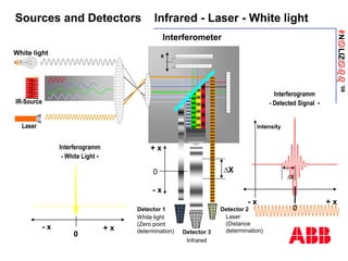
From Raw Spectrum to Absorbance
0
20
40
60
80
5000 4000 3000 2000 1000
- Raw gas -
spectrum
Intensity
0
.1
.2
.3
5000 4000 3000 2000 1000
Absorption
- Absorption -
spectrum
.6
.8
1
5000 4000 3000 2000 1000
Transmission
- Transmission -
spectrum
0
20
40
60
80
5000 4000 3000 2000 1000
Wavenumber n [ cm -1 ]
Intensity
- Reference Spectrum -
( Zero Spectrum )
I0
I
T = I / I0
E = - ln T
CO SO2
Wavenumber n [ cm -1 ]
Lambert Beer Law: I/Io = e-ε*c*l
ANaLIZabb
’08
ABB Spectrometer
Split Architecture Design
= Separation Between Gas Path and Electronics
Interferometer
Laser
Detector
IR Source
PC board
Spectrometer cover
Transfer optics
Heated gas cell
Aspirator Block Heated
sample line
Mirrors
O2 Sensor
Cell insulation
ANaLIZabb
’08
FTIR-Spectrometer with Interferometer
Gas Cell
Ir- Source
Ir- Detector
Interferometer
ANaLIZabb
’08
Sample Gas Cell
ANaLIZabb
’08
Gas Sampling Elements Summary
 One sampling point for all components
 Lower Installation cost
 Completely heated at 180 °C
 No risk of condensation before measurement
 Proven air aspirator pump & diluted gas at the cell outlet
 No moving parts, no corrosion
 Electronic flow control of the aspiration
 Accurate pressure and temperature correction
 Proven extractive sampling technology
 No delicate optics or electronics at the stack
ANaLIZabb
’08
Measuring Methods
VOC - Measurement
 EN 12619 is setting the standard for TOC - measurement, worked out by the CEN
 The FID is the only permitted principle of the technique.
 FID – method is independent valid, notwithstanding under which approval
a plant gets release for operation by the regional authorities.
 Standard agreed by all CEN member countrie.
For all other measuring components exists EN - Standards too.
ANaLIZabb
’08
ACF-NT System Block-Diagram
Span
Zero
H2
FTIR
Spectrometer
In Out 1mm
Combustion
Air
Instrument Air
5 .. 7 bar
FID
Air purifier
ZrO2
Span Gas
FTIR
Zero
2% O2/N2
Zero O2
Zero FID
Catalyzer
?% CnHm
Span FID
Span SNE
Heater
PT 100
Heater
Heater
PT 100
ZrO2-Signal
Controller
SC-Block
Multi-FID 14 ASP/RGM11-Module
6
7 8
9
10
180 °C
180 °C
180 °C
180 °C
700 °C
180 °C
180 °C
ANaLIZabb
’08
ACF-NT Sample Conditioning Block (SC-Block)
ZrO2
MG- In
FID
ANaLIZabb
’08
ACF-NT Network
ZrO2
Multi FID14
DI/DO
AI/AO
System
controller
HUB
AO/DO/DI/AI implementation in ACF-NT (Option)
Dust
4 – 20mA
Modbus
Profibus
Modbus
Ethernet
Internal Bus
FTIR controller
DAQ
FTIR
HMI
ANaLIZabb
’08
ACF-NT Features
 Measuring up to 12 components continuously
 Complete pre-engineered system
 6 months maintenance interval
 Proven hot wet extractive measurement technique
 High stability
 Fully integrated VOC & O2 – measurement
 Unique air-driven injector pump. No moving parts
ANaLIZabb
’08
ACF-NT Features
 All Analyzers from ABB
 VOC & O2 fully integrated
 Easy Operation - Single HMI
 Clear-text status messages
 Integration and display from other
measurements (p.e. dust, temp.)
Human Machine
Interface (front)
ANaLIZabb
’08
ACF-NT Features
 Recources saving calibration
concept without test gases for FTIR technology
 High availability through self-monitoring design
 Extra gas port for integration of a third party analyzer
 Communication
ACF-NT
Modbus
ANaLIZabb
’08
Future-oriented Communication Concept
ACF-NT
Dust
Head Office
Ethernet
Coupling
via OPC
or AnalyzeIT
Field bus
Coupling
e.g.
Profibus
Ethernet
via OPC
DCS
ABB
Support
Modem
coupling
I/Os
Internal Bus
coupling
ANaLIZabb
’08
Remote Service Support for Maintenance
Customer
Remote-Service
Worldwide !
 Tele-diagnostics & Status
 Temp. & Flow of sampling items
 Zero calibration
 FTIR Analyzer Error
 Remote Configuration
 Software Upgrade
 Maintenance request
 FTIR-Analyzer
ANaLIZabb
’08
ABB Service at Spain
Xavier Pedescoll
Manager
David Bernal
Service Engineer
Luis Machay
Service Engineer
Javier Guerrero
Service Engineer
Eduardo Fernandez
Service Engineer
ANaLIZabb
’08
ACF-NT 3rd Generation
1993
Cemas-FTIR
1996
Advance
Cemas-FTIR
2002
ACF-NT
300 Systems > 650 Systems
ANaLIZabb
’08
The 500th ACF-NT
Deliverd to the Holcim Cement plant in Lorca, in the province of Murcia
ANaLIZabb
’08
Continuous Gas Analysis
Advanced solutions for smart systems

P 3_Spain_ACF-NT_Hbl_01.ppt

  • 1.
  • 2.
    ANaLIZabb ’08 ACF-NT The leadingMulti-Component CEM-System
  • 3.
    ANaLIZabb ’08 ACF-NT Table ofContents  Legislation  Application  Approvals  Pre-engineered solution  Spectromter  Communication  Remote Control  Service
  • 4.
    ANaLIZabb ’08 The Hierarchy ofLegislation Air Quality Policy Directive 96/61/CE - Integrated Pollution Prevention & Control Directive 96/62/EC - Air Quality Framework Directive 2000/76/EC – Waste Incineration & Co-Incineration Directive 2001/80/EC – Large Combustion Plants Directive 2001/81/EC – National Emission Ceilings CAFE Program (Clean Air for Europe) International Treaties EU Legislation National Legislation Regional & Local Legislation Sofia Protocol – NOx Protocol Gothenburg Protocol Kyoto Protocol – Greenhouse Gases • Law Making • Law Enforcing • Permitting • Monitoring & Control
  • 5.
    ANaLIZabb ’08 Emission Monitoring according2000/76/EC WID ELV 1) Daily average Values Half - hourly average values Certified Measuring Method Component Hydrogene chloride HCL 10 mg/m³ NDIR / FTIR Hydrogen fluoride HF 1 mg/m³ 4 mg/³ NDIR / FTIR Sulphur dioxide SO2 50 mg/m³ 200 mg/m³ NDIR / FTIR Nitrogen monoxide + Nitrogen dioxide 2) NOx ( NO + NO2 ) 200 mg/m³ 400 mg/m³ NDIR / FTIR Total organic carbons TOC 10 mg/m³ 20 mg/m³ FID Oxygen 3) O2 Electrochem. Cell Paramagnetic Extract of the pollutants to be monitored 1) Emission Limit Value. Measuring ranges are based to the ELV with 1,5 times 2) Sum of NO+NO2 . NO2 needs to be measured if concentration is > 5% of NO 3) Reference value. Typical 0…25 Vol% MR.
  • 6.
    ANaLIZabb ’08 Emission Monitoring according2001/80/EC LCP Extract of pollutants to be monitored using coal firing ELV 1) Daily average values Half hourly average values Certified Measuring Method Component Carbon monoxide CO 200 mg/m³ 400 mg/m³ NDIR / FTIR Sulfur dioxide SO2 50 mg/m³ 200 mg/m³ NDIR / FTIR NOx ( NO + NO2 ) 200 mg/m³ 400 mg/m³ NDIR / FTIR Oxygen 3) O2 Electrochem. Cell Paramagnetic Nitrigen monoxide + Nitrogen dioxide 2) 1) Emission Limit Value. Measuring ranges are based to the ELV with 2,5 times 2) Sum of NO+NO2 . NO2 needs to be measured if concentration is > 5% of NO 3) Reference value. Typical 0…25 Vol% MR.
  • 7.
    ANaLIZabb ’08 Development of PollutantEmissions CAFE = Clean Air for Europe Program
  • 8.
    ANaLIZabb ’08 Interweaving the EuropeanRegulations & Directives Directive 2001/80/EC Large Combustion Plants LCPs For example TÜV testing accord. EN 15267-3 Directive 2000/76/EC Waste Incineration Plants & Co-Incineration (p.e. Cement) EN 14181 Stationary source emissions Quality assurance of Automated Measuring Systems (AMS) Come into force on Nov. 27, 2004 QAL 1 Basic suitability of the measuring system for the measuring task (EN ISO 14956) QAL 2 Installation and calibration of the AMS, determination of measurement uncertainty and check for maintaining permissible measurement uncertainties QAL 3 Regular drift control of the AMS during operation AST Annual surveillance test Testing and calibration laboratories needs authorization in accordance to EN / ISO / IEC 17025 CDM Projects
  • 9.
    ANaLIZabb ’08 Main Requirements forCEM Systems  Avaliability  No more than 10 daily average values per year shall be invalid caused by mailfunction or maintenance of the AMS (Automated Measuring System).   10days / 365days operation = 97% uptime required  Abnormal Operating Conditions  In case of a breakdown (including measurement device), the operator shall reduce or close down operations.  Important  High-standard measurement techniques are required to monitor pollutant emissions
  • 10.
    ANaLIZabb ’08 ACF-NT • Applications CEM System for Emission Monitoring at  Waste Incinerators  Sludge Incinerators  Power plants  Co-incinerator processes  Catalyst protection monitoring  Cement Kilns  Co-incineration processes  ... and all combustion processes which has to fulfil the EN standards for CEMS
  • 11.
    ANaLIZabb ’08 ACF-NT Approvals toCEM - Standards  Certification and Compliance to international Standards  EU Directives 2000/76/EC Waste Incineration & Co-Incineration 2001/80/EC Large Combustion Plants  EN 14181 Quality Assurance fulfilled  Complies with  EU – TÜV  UK – MCERTS  US & Canada  EPA  ASTM  CSA 6 months maintenance tested
  • 12.
    ANaLIZabb ’08 ACF-NT Performance  lowdetection limits  high selectivity  high linearity  high repeatability  high stability  high availability  fast response  low maintenance cost  low cost per component  Long maintenance interval
  • 13.
    ANaLIZabb ’08 ACF-NT Pre-Engineered Solution Complete System for Multi-Component Measurement  Continuously Operating System  Extractive Measurement - Hot / Wet  Sample Probe & Preparation  Analysis based on ABB – Technology Best available technology for monitoring low ranges of reactive gases such as: HCl, HF and NH3 …  Communication, conventional and modern serial interfaces Modbus
  • 14.
    ANaLIZabb ’08  Hydrogen ChlorideHCl  Sulphur Dioxide SO2  Hydrogen Flouride HF  Volatile Hydro-Carbons VOC  Ammonia NH3 ACF-NT Engineering Why measuring hot ?  Some Gases are easily lost by condensation  To prevent acid condensation hot design (180°C) is necessary  Nitrogen Oxides NOx  Nitrous Oxide N2O  Carbon Monoxide CO  Carbon Dioxide CO2  Oxygen O2
  • 15.
    ANaLIZabb ’08 ACF-NT Measuring components- and Ranges Smallest ranges Typical  Other Components on request Testgas Air Testgas FID & O2 I/O HMI1 25 Vol% O2 Plausibility Test Spectrometer Oxygen Measurement 5 mg/m3 HF 15 mg/m3 HCl 40 Vol% H2O 75 mg/m3 SO2 15 mg/m3 VOC 50 mg/m3 N2O 15 mg/m3 NH3 40 mg/m3 NO2 200 mg/m3 NO 30 Vol% CO2 75 mg/m3 CO Multi FID14 ACF-NT FTIR Zirconia Flame Ionization Measuring Ranges 200 mg/m³ 25 Vol% 400 mg/m³ 80 mg/m³ 15 mg/m³ 100 mg/m³ 300 mg/m³ 40 / 60 Vol% 90 mg/m³ 6 mg/m³ 30 mg/m³ 25 Vol% Range switchover possible 75 / 300 mg/m³ 200 / 400 mg/m³ 75 / 300 mg/m³ 15 / 90 mg/m³ ratio max 1 : 4
  • 16.
    ANaLIZabb ’08 ACF-NT FTIR -Flow Diagram 1 Probe tube 2 Heated filter 3 Heated sampling line 4 Stainless steel filter 5 Heated meas. cell 6 FTIR spectrometer 13 Switch test gas local or probe. Emergency purge 14 Check valve 15 FID port 16 Port for 3rd party analyzer 9 6 11 12 Test gas 1 2 Compressed Air 13 5 10 3 4 8 16 Gas Outlet 15 7 14 7 ZrO2 Sensor (option) 8 Aspirator pump 9 Spectrometer purge 10 Compressed air cleaner 11 Zero gas solenoid 12 Test gas solenoid Sample Gas
  • 17.
    ANaLIZabb ’08 Filter Unit PFE2 Filterunit FE2 with Heating sleeve + Temerature controller + Filter Unit PFE2
  • 18.
    ANaLIZabb ’08 Heated sample gasline Probe tube Wall Wall tube Filter Unit PFE2 Heating Gas Sampling Probe • Typical Installation Mounting angle 8°... 90° downwards One single sample point required for all measured components
  • 19.
    ANaLIZabb ’08 Gas Sampling Probe• Typical Installation Insulation required
  • 20.
    ANaLIZabb ’08 Modular Sample ProbeSystem - Probe Tube 42 heated Wall tube for probe
  • 21.
    ANaLIZabb ’08 Modular Sample ProbeSystem - Probe Tube 42 heated Pt 100 sensor Terminal box Suitable for: - Low temperature (<180 °C, high dewpoint, Water or acid - Stack with brick walls in a tube in tube construction Power supply PT100 Sensor
  • 22.
    ANaLIZabb ’08 Heated Sample GasLine TBL01-S Design Example  Flange Adapter  Outer shielding with corrugated bundle hose
  • 23.
    ANaLIZabb ’08 ACF-NT FTIR Spectrometer The core of the ACF-NT ABB-Bomem Michelson Interferometer  FT-IR Fourier Transform InfraRed – Spectroscopy
  • 24.
    ANaLIZabb ’08 ACF-NT Photometry Basics Polyatomicmolecules  Absorption at specific wavelengths HCl l = 3.4 µm Symmetrical molecules  Transparent to IR N2 l = 2 - 25 µm  Measurement of all infrared active components at the same time  All molecules consisting of 3 and more atoms and all di-atomic heteronuclear molecules absorb infrared radiation Example CO, NO, SO2 But not N2, O2, Hg
  • 25.
  • 26.
    ANaLIZabb ’08 FTIR Interferometer Light incidentonto the 2 mirrors IR-Detector Beam splitter Fixed mirror LASER : 1 single wavelength I l time Interferogram I x Moving mirror x Light reflected from the moving mirror Fourier Transformation Spectrum frequency I with half transparent lay Interference as function of mirror displacement
  • 27.
    ANaLIZabb ’08 Interferometer ( FourierTransfrom Infra Red ) IR - Detector IR- Source 4 - 20 mA Interfero- meter Multiplexer CO, SO2/N2 Cell Intensity Wavelength Intensity Wavelength lz lz2 lz3 lz1 Intensity Wavelength lz2 lz3 lz1 Modulator
  • 28.
    ANaLIZabb ’08 Sources and DetectorsInfrared - Laser - White light Interferometer x DX White light + x - x 0 0 + x - x Interferogramm - White Light - Detector 3 Infrared Laser (Distance determination) Detector 2 Detector 1 White light (Zero point determination) DX + x - x 0 Intensity Laser IR-Source Interferogramm - Detected Signal -
  • 29.
    ANaLIZabb ’08 From Interferogram tospectrum 0 20 40 60 80 5000 4000 3000 2000 1000 Function of Frequency (sec-1) or Wavenumber (cm-1) Raw Spectrum -X Mirror Displacement (in cm) = Function of Time (sec) 0 +X Intensity Interferogram FT Measurement of light intensity as a function of time (sec) or mirror displacement (cm) conversion
  • 30.
    ANaLIZabb ’08 From Raw Spectrumto Absorbance 0 20 40 60 80 5000 4000 3000 2000 1000 - Raw gas - spectrum Intensity 0 .1 .2 .3 5000 4000 3000 2000 1000 Absorption - Absorption - spectrum .6 .8 1 5000 4000 3000 2000 1000 Transmission - Transmission - spectrum 0 20 40 60 80 5000 4000 3000 2000 1000 Wavenumber n [ cm -1 ] Intensity - Reference Spectrum - ( Zero Spectrum ) I0 I T = I / I0 E = - ln T CO SO2 Wavenumber n [ cm -1 ] Wavenumber n [ cm -1 ] Wavenumber n [ cm -1 ] Lambert Beer Law: I/Io = e-ε*c*l
  • 31.
    ANaLIZabb ’08 ABB Spectrometer Split ArchitectureDesign = Separation Between Gas Path and Electronics Interferometer Laser Detector IR Source PC board Spectrometer cover Transfer optics Heated gas cell Aspirator Block Heated sample line Mirrors O2 Sensor Cell insulation
  • 32.
    ANaLIZabb ’08 FTIR-Spectrometer with Interferometer GasCell Ir- Source Ir- Detector Interferometer
  • 33.
  • 34.
    ANaLIZabb ’08 Gas Sampling ElementsSummary  One sampling point for all components  Lower Installation cost  Completely heated at 180 °C  No risk of condensation before measurement  Proven air aspirator pump & diluted gas at the cell outlet  No moving parts, no corrosion  Electronic flow control of the aspiration  Accurate pressure and temperature correction  Proven extractive sampling technology  No delicate optics or electronics at the stack
  • 35.
    ANaLIZabb ’08 Measuring Methods VOC -Measurement  EN 12619 is setting the standard for TOC - measurement, worked out by the CEN  The FID is the only permitted principle of the technique.  FID – method is independent valid, notwithstanding under which approval a plant gets release for operation by the regional authorities.  Standard agreed by all CEN member countrie. For all other measuring components exists EN - Standards too.
  • 36.
    ANaLIZabb ’08 ACF-NT System Block-Diagram Span Zero H2 FTIR Spectrometer InOut 1mm Combustion Air Instrument Air 5 .. 7 bar FID Air purifier ZrO2 Span Gas FTIR Zero 2% O2/N2 Zero O2 Zero FID Catalyzer ?% CnHm Span FID Span SNE Heater PT 100 Heater Heater PT 100 ZrO2-Signal Controller SC-Block Multi-FID 14 ASP/RGM11-Module 6 7 8 9 10 180 °C 180 °C 180 °C 180 °C 700 °C 180 °C 180 °C
  • 37.
    ANaLIZabb ’08 ACF-NT Sample ConditioningBlock (SC-Block) ZrO2 MG- In FID
  • 38.
    ANaLIZabb ’08 ACF-NT Network ZrO2 Multi FID14 DI/DO AI/AO System controller HUB AO/DO/DI/AIimplementation in ACF-NT (Option) Dust 4 – 20mA Modbus Profibus Modbus Ethernet Internal Bus FTIR controller DAQ FTIR HMI
  • 39.
    ANaLIZabb ’08 ACF-NT Features  Measuringup to 12 components continuously  Complete pre-engineered system  6 months maintenance interval  Proven hot wet extractive measurement technique  High stability  Fully integrated VOC & O2 – measurement  Unique air-driven injector pump. No moving parts
  • 40.
    ANaLIZabb ’08 ACF-NT Features  AllAnalyzers from ABB  VOC & O2 fully integrated  Easy Operation - Single HMI  Clear-text status messages  Integration and display from other measurements (p.e. dust, temp.) Human Machine Interface (front)
  • 41.
    ANaLIZabb ’08 ACF-NT Features  Recourcessaving calibration concept without test gases for FTIR technology  High availability through self-monitoring design  Extra gas port for integration of a third party analyzer  Communication ACF-NT Modbus
  • 42.
    ANaLIZabb ’08 Future-oriented Communication Concept ACF-NT Dust HeadOffice Ethernet Coupling via OPC or AnalyzeIT Field bus Coupling e.g. Profibus Ethernet via OPC DCS ABB Support Modem coupling I/Os Internal Bus coupling
  • 43.
    ANaLIZabb ’08 Remote Service Supportfor Maintenance Customer Remote-Service Worldwide !  Tele-diagnostics & Status  Temp. & Flow of sampling items  Zero calibration  FTIR Analyzer Error  Remote Configuration  Software Upgrade  Maintenance request  FTIR-Analyzer
  • 44.
    ANaLIZabb ’08 ABB Service atSpain Xavier Pedescoll Manager David Bernal Service Engineer Luis Machay Service Engineer Javier Guerrero Service Engineer Eduardo Fernandez Service Engineer
  • 45.
  • 46.
    ANaLIZabb ’08 The 500th ACF-NT Deliverdto the Holcim Cement plant in Lorca, in the province of Murcia
  • 47.