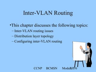
![CCNP BCMSN Module 328/76
Switch (enable)set spantree root [secondary] <vlans> [dia
network_diameter] [hello hello_time]
Modifying the Root Selection
Setting the spantree root determines which
device is more likely to become the root bridge.](https://image.slidesharecdn.com/chap3-140825035916-phpapp02/85/Managing-Redundant-Links-Inter-VLAN-Routing-28-320.jpg)
![CCNP BCMSN Module 336/76
Switch (enable) set spantree fwddelay delay [vlan]
Switch (enable) set spantree maxage agingtime [vlan]
Switch (enable) set spantree hello hello_interval
Modifying Default Timers
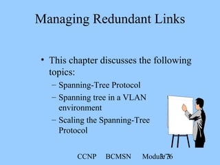
• Modify the default timers during spanning tree
instability.
• Use other methods to influence convergence.](https://image.slidesharecdn.com/chap3-140825035916-phpapp02/85/Managing-Redundant-Links-Inter-VLAN-Routing-36-320.jpg)
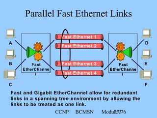
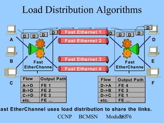
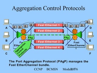
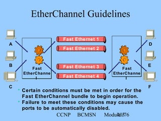
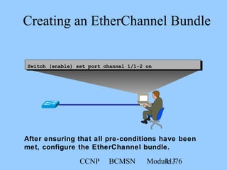
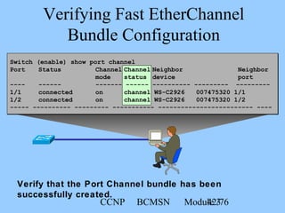
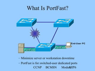
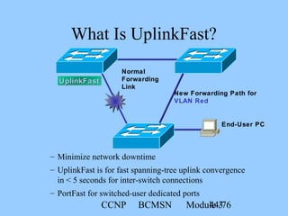
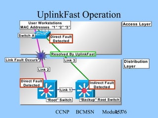
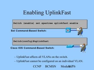
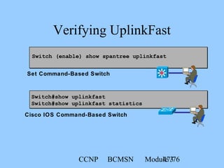
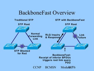
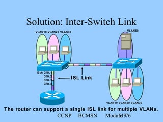
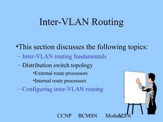

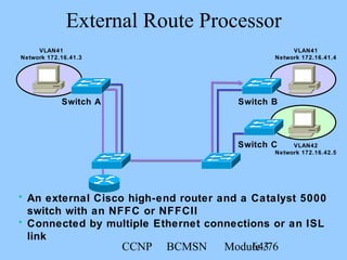
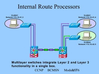
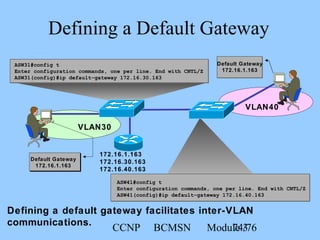
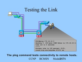
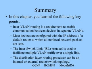
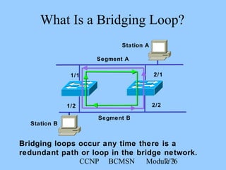
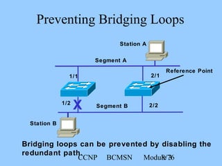
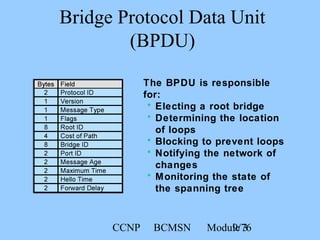
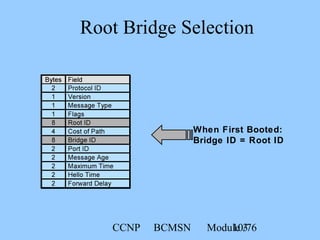
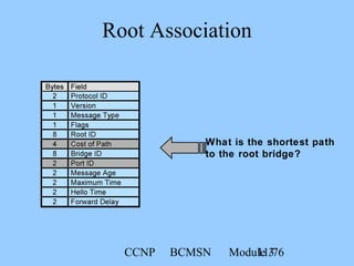
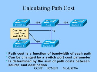
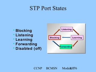
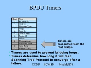
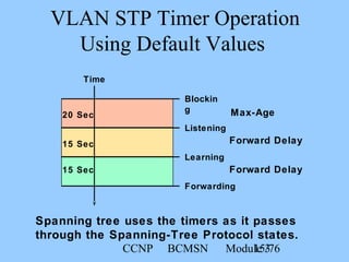
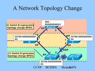
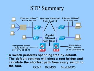
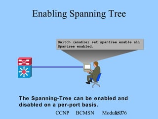
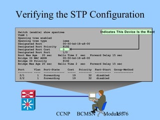
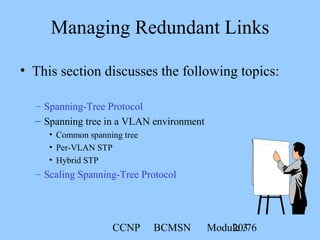
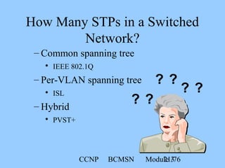
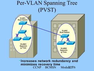
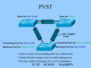
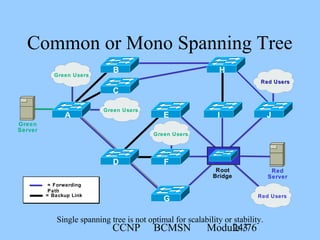
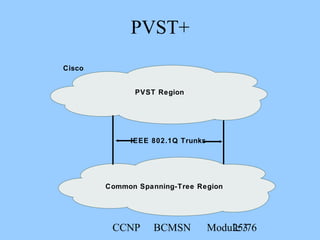
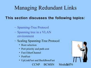
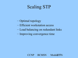
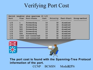
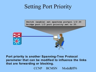
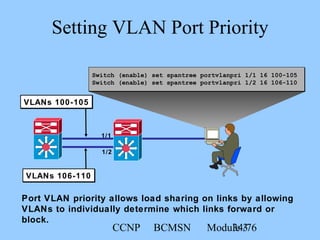
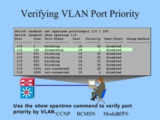
This document discusses managing redundant links and spanning tree protocols. It describes spanning tree protocol (STP) operations including electing a root bridge, path cost calculations, port states and BPDU timers. It also covers spanning tree in VLAN environments, such as per-VLAN STP (PVST), and techniques for scaling STP, including modifying root selection, path costs, port priorities and timers. Other topics include Fast EtherChannel, PortFast and UplinkFast for improving convergence times.