Downloaded 43 times


![4
wg_ro_a#show flash
System flash directory:
File Length Name/status
1 10084696 c2500-js-l_120-3.bin
[10084760 bytes used, 6692456 available, 16777216 total]
16384K bytes of processor board System flash (Read ONLY)
Verifying Memory Image
Filenames](https://image.slidesharecdn.com/ccna-day5-140715152501-phpapp01/85/Ccna-day5-4-320.jpg)
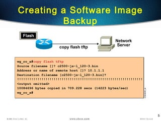
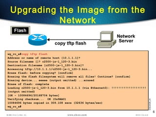
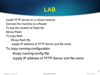
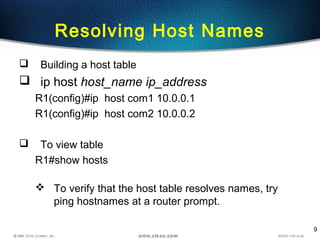
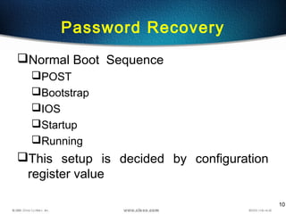
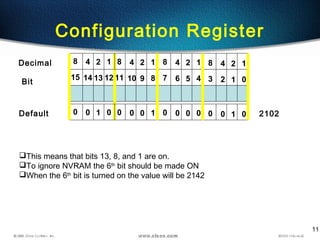
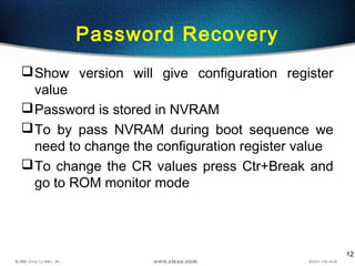
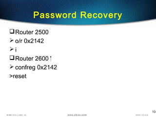

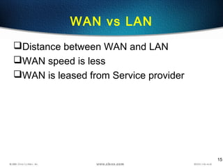
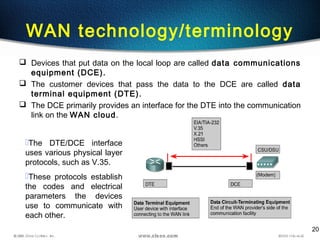
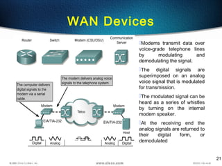
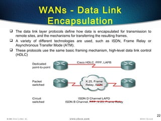
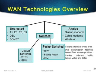
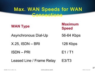
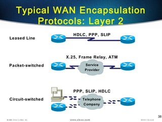
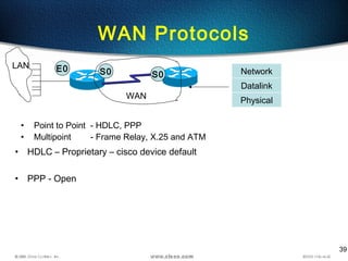
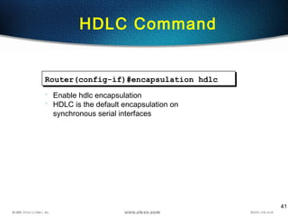
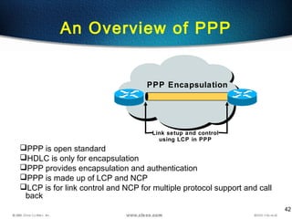
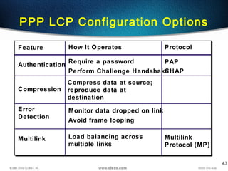
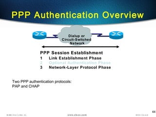
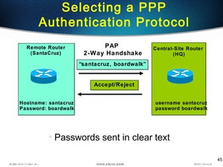
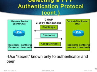
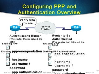
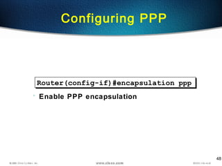
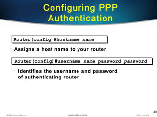
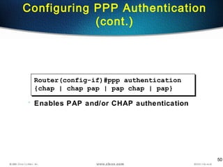
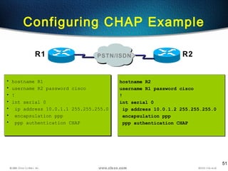
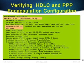

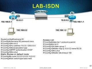
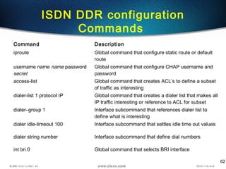

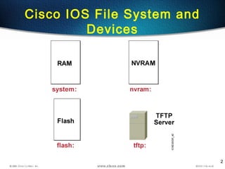
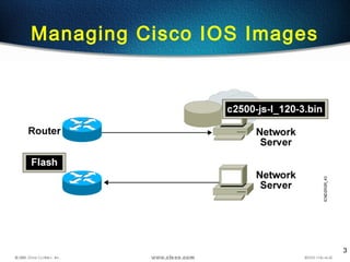
The document discusses managing Cisco IOS images and configuring WAN connections. It covers topics such as copying flash images using TFTP, resolving hostnames, password recovery, and configuring encapsulation protocols like HDLC and PPP. Specific configuration examples are provided for setting the CHAP authentication protocol on serial interfaces between two routers.


