The document provides instructions for disassembling and assembling various components of a Caterpillar 3306 vehicular engine used in a 977L track loader, including:
- Removing and installing the camshaft, following marks to maintain proper timing.
- Removing and installing timing gears and plate, using tools to apply torque and ensure proper alignment.
- Removing the engine and torque converter by disconnecting hoses, wires, and supports, and reinstalling by reversing the process.
- Removing the flywheel by loosening bolts and installing guide bolts, and reinstalling it along with heating and installing the ring gear.
The document provides instructions for disassembling and assembling various components of a 955K track loader engine, including:
1) Separating and reconnecting the governor from the fuel injection pump housing.
2) Disassembling and reassembling the governor.
3) Removing and installing the fuel check valve and bypass valve.
4) Taking out and putting in the fuel injection pumps.
5) Taking apart and rebuilding the fuel injection pumps.
1. The document provides instructions for disassembling and assembling various components of a 955K track loader engine, including the governor, fuel injection pumps, fuel check valve, and bypass valve.
2. Steps are provided to separate the governor from the fuel injection pump housing, disassemble the governor, remove and install the fuel check valve and bypass valve, remove and install the fuel injection pumps, and disassemble and assemble the fuel injection pumps.
3. Cleaning procedures and special notes are included throughout to ensure correct assembly.
The document provides instructions for disassembling and assembling various components of a 955K track loader engine, including:
1) Separating and reconnecting the governor from the fuel injection pump housing.
2) Disassembling and assembling the governor.
3) Removing and installing the fuel check valve and bypass valve.
The instructions are presented in a step-by-step format with pictures to aid in the process. Proper installation of parts is emphasized to ensure correct engine operation.
This document provides instructions for disassembling and assembling various components of a Caterpillar 3306 vehicular engine, including the governor, fuel transfer pump, fuel check valve, bypass valve, fuel injection pumps, and hood/muffler/precleaner assembly. It describes removing and installing each part in 3 sentences or less, noting key steps like using specific tools, installing parts in their original positions, and ensuring proper orientation of seals and other components.
This document provides instructions for disassembling and assembling various components of a Caterpillar 3306 vehicular engine, including the governor, fuel transfer pump, fuel check valve, bypass valve, fuel injection pumps, and hood/muffler/precleaner assembly. It lists the specific parts to remove and install for each component, and the order and important notes for the process. Disassembly generally involves removing covers, seals, springs, pins, and internal parts. Reassembly follows the reverse order and notes proper orientation of parts.
This document provides instructions for disassembling and assembling various components of a 977K Track Loader engine, including the governor, fuel transfer pump, fuel check valve, fuel injection pumps, and hood/muffler/precleaner assembly. It describes removing and installing each part in 3 sentences or less per component, identifying start and end steps and noting important details like installation order and specific tools required.
This document provides instructions for disassembling and assembling various components of a 977K track loader, including the fuel injection pump housing, governor, and engine. The instructions include removing and installing over 50 individual parts in a specific sequence, noting identification numbers, lubrication, and torque specifications where relevant. Key steps include separating the governor from the fuel injection pump housing, removing the fuel injection pumps, camshaft and other internal parts, and correctly reinstalling them while aligning pins, levers and shafts.
The document provides instructions for disassembling and assembling various components of a 955K track loader engine, including:
1) Separating and reconnecting the governor from the fuel injection pump housing.
2) Disassembling and reassembling the governor.
3) Removing and installing the fuel check valve and bypass valve.
4) Taking out and putting in the fuel injection pumps.
5) Taking apart and rebuilding the fuel injection pumps.
1. The document provides instructions for disassembling and assembling various components of a 955K track loader engine, including the governor, fuel injection pumps, fuel check valve, and bypass valve.
2. Steps are provided to separate the governor from the fuel injection pump housing, disassemble the governor, remove and install the fuel check valve and bypass valve, remove and install the fuel injection pumps, and disassemble and assemble the fuel injection pumps.
3. Cleaning procedures and special notes are included throughout to ensure correct assembly.
The document provides instructions for disassembling and assembling various components of a 955K track loader engine, including:
1) Separating and reconnecting the governor from the fuel injection pump housing.
2) Disassembling and assembling the governor.
3) Removing and installing the fuel check valve and bypass valve.
The instructions are presented in a step-by-step format with pictures to aid in the process. Proper installation of parts is emphasized to ensure correct engine operation.
This document provides instructions for disassembling and assembling various components of a Caterpillar 3306 vehicular engine, including the governor, fuel transfer pump, fuel check valve, bypass valve, fuel injection pumps, and hood/muffler/precleaner assembly. It describes removing and installing each part in 3 sentences or less, noting key steps like using specific tools, installing parts in their original positions, and ensuring proper orientation of seals and other components.
This document provides instructions for disassembling and assembling various components of a Caterpillar 3306 vehicular engine, including the governor, fuel transfer pump, fuel check valve, bypass valve, fuel injection pumps, and hood/muffler/precleaner assembly. It lists the specific parts to remove and install for each component, and the order and important notes for the process. Disassembly generally involves removing covers, seals, springs, pins, and internal parts. Reassembly follows the reverse order and notes proper orientation of parts.
This document provides instructions for disassembling and assembling various components of a 977K Track Loader engine, including the governor, fuel transfer pump, fuel check valve, fuel injection pumps, and hood/muffler/precleaner assembly. It describes removing and installing each part in 3 sentences or less per component, identifying start and end steps and noting important details like installation order and specific tools required.
This document provides instructions for disassembling and assembling various components of a 977K track loader, including the fuel injection pump housing, governor, and engine. The instructions include removing and installing over 50 individual parts in a specific sequence, noting identification numbers, lubrication, and torque specifications where relevant. Key steps include separating the governor from the fuel injection pump housing, removing the fuel injection pumps, camshaft and other internal parts, and correctly reinstalling them while aligning pins, levers and shafts.
The document provides step-by-step instructions for disassembling and assembling the transmission and transfer gears of a 977K track loader. It details removing over 30 individual components in the disassembly process, including the transmission case, selector valve, bearings, and input shaft. Reassembly requires properly cleaning and replacing seals on each part before reinstalling the components in the reverse order of disassembly.
This document provides instructions for disassembling the front and rear final drive carriers, hubs, and brakes of an M320 Excavator. The multi-step procedures include draining fluids, removing mounting bolts and pins, using specialty tools to separate connected parts, and disassembling individual components like planetary gears, brake pistons, seals, and bearings. Safety notices are included to warn of fluid hazards and proper handling of pressurized hydraulic systems during disassembly. Required specialty tools are listed for each step.
This document provides instructions for disassembling the front and rear final drive carriers, hubs, and brakes of an M320 excavator. The multi-step procedures include removing drain plugs, bolts, gears, washers, seals, bearings, and other components. Detailed illustrations accompany each step to ensure safe and proper disassembly. Required tools are listed for each job.
This document provides instructions for disassembling the front and rear final drive carriers, hubs, and brakes of an M320 excavator. The multi-step procedures include draining fluids, removing mounting bolts, using various specialty tools to separate components, and disassembling individual parts like planetary gears, brake pistons, bearings, and seals. Precautions are provided regarding fluid handling and ensuring parts are properly marked for reassembly.
This document provides instructions for disassembling and assembling components of the fuel injection system for a 245 Excavator model 95V engine, including:
- Removing and installing the fuel injection pump housing, which involves disassembling the pumps and housing components and reassembling them in the proper order.
- Removing and installing the inlet manifold, which is the part that connects the air cleaner to the cylinder head.
- Removing and installing the aftercooler, which cools the air after it passes through the turbocharger, and involves disconnecting hoses and removing housing pieces.
This document provides instructions for disassembling and assembling components of the fuel injection system for a 245 Excavator model engine. The document describes how to disassemble and assemble the fuel injection pump housing, which includes removing pumps, gears, and other internal components. It also provides instructions for removing and installing the inlet manifold and aftercooler. The steps provided are detailed and include images to illustrate the proper procedures.
Caterpillar Cat 245 EXCAVATOR (Prefix 95V) Service Repair Manual (95V00001-00...f8usjejkdmmd
This document provides instructions for disassembling and assembling components of the fuel injection system for a 245 Excavator model engine. The document describes how to disassemble and assemble the fuel injection pump housing, which includes removing pumps, gears, and other internal components. It also provides instructions for removing and installing the inlet manifold and aftercooler. The steps provided are detailed and include images to illustrate the proper procedures.
This document provides instructions for disassembling and assembling components of the fuel injection system for a 245 Excavator model engine. The document describes how to disassemble and assemble the fuel injection pump housing, which includes removing pumps, gears, and other internal components. It also provides instructions for removing and installing the inlet manifold and aftercooler. The procedures provide detailed steps for servicing these engine systems while ensuring proper identification and replacement of parts.
Caterpillar Cat 245 EXCAVATOR (Prefix 95V) Service Repair Manual (95V00001-00...fujsked9dikdkd
This document provides instructions for disassembling and assembling components of the fuel injection system for a 245 Excavator model 95V engine, including:
- Removing and installing the fuel injection pump housing, which involves disassembling the pumps and housing components and reassembling them in the proper order.
- Removing and installing the inlet manifold, which is the part that connects the air cleaner to the cylinder head.
- Removing and installing the aftercooler, which cools the air after it passes through the turbocharger, and involves disconnecting hoses and removing housing pieces.
Caterpillar Cat 245 EXCAVATOR (Prefix 95V) Service Repair Manual (95V00001-00...ufjskekdjdmw2
This document provides instructions for servicing components of a 245 Excavator engine, including:
- Disassembling and reassembling the fuel injection pump housing, which involves removing pumps, gears, and bearings, and reinstalling them in the proper order and position.
- Removing and installing the inlet manifold, which connects to the cylinder head and air cleaner components.
- Removing the aftercooler unit, which cools engine air after turbocharging, by disconnecting hoses and removing housing covers, elbows, and the core component.
Caterpillar Cat 245 EXCAVATOR (Prefix 95V) Service Repair Manual (95V00001-00...gen78guozun
This document provides instructions for servicing components of a 245 Excavator's 3406 vehicular engine, including:
- Disassembling and reassembling the fuel injection pump housing, which involves removing various parts like pumps, racks, lifters, and bearings, and replacing them in the proper order.
- Removing and installing the inlet manifold, which connects to the cylinder head and air cleaner components.
- Removing the aftercooler unit, which involves disconnecting hoses and pipes, removing mounting bolts, and taking out the core component. Detailed steps are provided for each disassembly and reassembly process.
Caterpillar Cat 245 EXCAVATOR (Prefix 95V) Service Repair Manual (95V00001-00...fjskemmd4r
This document provides instructions for disassembling and assembling components of the fuel injection system for a 245 Excavator model 95V engine, including:
- Removing and installing the fuel injection pump housing, which involves disassembling the pumps and housing components and reassembling them in the proper order.
- Removing and installing the inlet manifold, which is the part that connects the air cleaner to the cylinder head.
- Removing and installing the aftercooler, which cools the air after it passes through the turbocharger, and involves disconnecting hoses and removing housing pieces.
Caterpillar Cat 245 EXCAVATOR (Prefix 95V) Service Repair Manual (95V00001-00...jfkksemmdmd
This document provides instructions for disassembling and assembling components of the fuel injection system for a 245 Excavator model 95V engine, including:
- Removing and installing the fuel injection pump housing, which involves disassembling the pumps and housing components and reassembling them in the proper order.
- Removing and installing the inlet manifold, which is the part that connects the air cleaner to the cylinder head.
- Removing and installing the aftercooler, which cools the air after it passes through the turbocharger, and involves disconnecting hoses and removing housing pieces.
This document provides instructions for disassembling and assembling components of the fuel injection system for a 245 Excavator model 95V engine, including:
- Removing and installing the fuel injection pump housing, which involves disassembling the pumps and housing components and reassembling them in the proper order.
- Removing and installing the inlet manifold, which is the part that connects the air intake to the cylinder head.
- Removing and installing the aftercooler, which cools the air after it passes through the turbocharger, and involves disconnecting hoses and removing housing pieces.
This document provides instructions for disassembling and assembling components of the fuel injection system for a 3406 vehicular engine used in 245 excavators. The document describes how to disassemble and assemble the fuel injection pump housing by removing pumps, gears, and other internal components. It also provides instructions for removing and installing the inlet manifold, aftercooler, and related components. The purpose is to provide technicians with step-by-step guidance for servicing and repairing parts of the fuel system.
This document provides instructions for disassembling and assembling components of the fuel injection system for a 3406 vehicular engine used in 245 excavators. The document describes how to disassemble and assemble the fuel injection pump housing by removing pumps, gears, and other internal components. It also provides instructions for removing and installing the inlet manifold, aftercooler, and related components. The purpose is to repair or replace parts while maintaining proper installation and alignment of components.
Massey Ferguson MF 384 S TRACTOR (- 300993) Parts Catalogue Manual Instant Do...gua6982552kun
This document contains parts listings and technical specifications for the engine of a Massey Ferguson 384 S tractor. It includes 6 pages detailing over 60 individual parts for the engine, including the cylinder block, crankshaft, pistons, cylinder head, rocker shaft, and air induction/exhaust systems. Each part is listed with its part number, quantity used, description, and any replacement or comment information.
Massey Ferguson MF 384 F TRACTOR, - 0894 Parts Catalogue Manual Instant Downl...gua6982552kun
The document is a parts catalog for a Massey Ferguson MF 384 F tractor engine. It lists over 60 individual parts for the engine, including the cylinder block, crankshaft, pistons, connecting rods, cylinder head, rocker shaft and other components. Each part is given a reference number, part number, quantity and description, along with any replacement or additional part information.
More Related Content
Similar to Caterpillar Cat 977K 977L TRACK LOADER (Prefix 48J) Service Repair Manual Instant Download (48J00586-01058).pdf
This document provides instructions for disassembling and assembling various components of a 977K track loader, including the fuel injection pump housing, governor, and engine. The instructions include removing and installing over 50 individual parts in a specific sequence, noting identification numbers, lubrication, and torque specifications where relevant. Key steps include separating the governor from the fuel injection pump housing, removing the fuel injection pumps, camshaft and other internal parts, and correctly reinstalling them while aligning pins, levers and shafts.
The document provides step-by-step instructions for disassembling and assembling the transmission and transfer gears of a 977K track loader. It details removing over 30 individual components in the disassembly process, including the transmission case, selector valve, bearings, and input shaft. Reassembly requires properly cleaning and replacing seals on each part before reinstalling the components in the reverse order of disassembly.
This document provides instructions for disassembling the front and rear final drive carriers, hubs, and brakes of an M320 Excavator. The multi-step procedures include draining fluids, removing mounting bolts and pins, using specialty tools to separate connected parts, and disassembling individual components like planetary gears, brake pistons, seals, and bearings. Safety notices are included to warn of fluid hazards and proper handling of pressurized hydraulic systems during disassembly. Required specialty tools are listed for each step.
This document provides instructions for disassembling the front and rear final drive carriers, hubs, and brakes of an M320 excavator. The multi-step procedures include removing drain plugs, bolts, gears, washers, seals, bearings, and other components. Detailed illustrations accompany each step to ensure safe and proper disassembly. Required tools are listed for each job.
This document provides instructions for disassembling the front and rear final drive carriers, hubs, and brakes of an M320 excavator. The multi-step procedures include draining fluids, removing mounting bolts, using various specialty tools to separate components, and disassembling individual parts like planetary gears, brake pistons, bearings, and seals. Precautions are provided regarding fluid handling and ensuring parts are properly marked for reassembly.
This document provides instructions for disassembling and assembling components of the fuel injection system for a 245 Excavator model 95V engine, including:
- Removing and installing the fuel injection pump housing, which involves disassembling the pumps and housing components and reassembling them in the proper order.
- Removing and installing the inlet manifold, which is the part that connects the air cleaner to the cylinder head.
- Removing and installing the aftercooler, which cools the air after it passes through the turbocharger, and involves disconnecting hoses and removing housing pieces.
This document provides instructions for disassembling and assembling components of the fuel injection system for a 245 Excavator model 95V engine, including:
- Removing and installing the fuel injection pump housing, which involves disassembling the pumps and housing components and reassembling them in the proper order.
- Removing and installing the inlet manifold, which is the part that connects the air cleaner to the cylinder head.
- Removing and installing the aftercooler, which cools the air after it passes through the turbocharger, and involves disconnecting hoses and removing housing pieces.
This document provides instructions for disassembling and assembling components of the fuel injection system for a 245 Excavator model engine. The document describes how to disassemble and assemble the fuel injection pump housing, which includes removing pumps, gears, and other internal components. It also provides instructions for removing and installing the inlet manifold and aftercooler. The steps provided are detailed and include images to illustrate the proper procedures.
Caterpillar Cat 245 EXCAVATOR (Prefix 95V) Service Repair Manual (95V00001-00...f8usjejkdmmd
This document provides instructions for disassembling and assembling components of the fuel injection system for a 245 Excavator model engine. The document describes how to disassemble and assemble the fuel injection pump housing, which includes removing pumps, gears, and other internal components. It also provides instructions for removing and installing the inlet manifold and aftercooler. The steps provided are detailed and include images to illustrate the proper procedures.
This document provides instructions for disassembling and assembling components of the fuel injection system for a 245 Excavator model engine. The document describes how to disassemble and assemble the fuel injection pump housing, which includes removing pumps, gears, and other internal components. It also provides instructions for removing and installing the inlet manifold and aftercooler. The procedures provide detailed steps for servicing these engine systems while ensuring proper identification and replacement of parts.
Caterpillar Cat 245 EXCAVATOR (Prefix 95V) Service Repair Manual (95V00001-00...fujsked9dikdkd
This document provides instructions for disassembling and assembling components of the fuel injection system for a 245 Excavator model 95V engine, including:
- Removing and installing the fuel injection pump housing, which involves disassembling the pumps and housing components and reassembling them in the proper order.
- Removing and installing the inlet manifold, which is the part that connects the air cleaner to the cylinder head.
- Removing and installing the aftercooler, which cools the air after it passes through the turbocharger, and involves disconnecting hoses and removing housing pieces.
Caterpillar Cat 245 EXCAVATOR (Prefix 95V) Service Repair Manual (95V00001-00...ufjskekdjdmw2
This document provides instructions for servicing components of a 245 Excavator engine, including:
- Disassembling and reassembling the fuel injection pump housing, which involves removing pumps, gears, and bearings, and reinstalling them in the proper order and position.
- Removing and installing the inlet manifold, which connects to the cylinder head and air cleaner components.
- Removing the aftercooler unit, which cools engine air after turbocharging, by disconnecting hoses and removing housing covers, elbows, and the core component.
Caterpillar Cat 245 EXCAVATOR (Prefix 95V) Service Repair Manual (95V00001-00...gen78guozun
This document provides instructions for servicing components of a 245 Excavator's 3406 vehicular engine, including:
- Disassembling and reassembling the fuel injection pump housing, which involves removing various parts like pumps, racks, lifters, and bearings, and replacing them in the proper order.
- Removing and installing the inlet manifold, which connects to the cylinder head and air cleaner components.
- Removing the aftercooler unit, which involves disconnecting hoses and pipes, removing mounting bolts, and taking out the core component. Detailed steps are provided for each disassembly and reassembly process.
Caterpillar Cat 245 EXCAVATOR (Prefix 95V) Service Repair Manual (95V00001-00...fjskemmd4r
This document provides instructions for disassembling and assembling components of the fuel injection system for a 245 Excavator model 95V engine, including:
- Removing and installing the fuel injection pump housing, which involves disassembling the pumps and housing components and reassembling them in the proper order.
- Removing and installing the inlet manifold, which is the part that connects the air cleaner to the cylinder head.
- Removing and installing the aftercooler, which cools the air after it passes through the turbocharger, and involves disconnecting hoses and removing housing pieces.
Caterpillar Cat 245 EXCAVATOR (Prefix 95V) Service Repair Manual (95V00001-00...jfkksemmdmd
This document provides instructions for disassembling and assembling components of the fuel injection system for a 245 Excavator model 95V engine, including:
- Removing and installing the fuel injection pump housing, which involves disassembling the pumps and housing components and reassembling them in the proper order.
- Removing and installing the inlet manifold, which is the part that connects the air cleaner to the cylinder head.
- Removing and installing the aftercooler, which cools the air after it passes through the turbocharger, and involves disconnecting hoses and removing housing pieces.
This document provides instructions for disassembling and assembling components of the fuel injection system for a 245 Excavator model 95V engine, including:
- Removing and installing the fuel injection pump housing, which involves disassembling the pumps and housing components and reassembling them in the proper order.
- Removing and installing the inlet manifold, which is the part that connects the air intake to the cylinder head.
- Removing and installing the aftercooler, which cools the air after it passes through the turbocharger, and involves disconnecting hoses and removing housing pieces.
This document provides instructions for disassembling and assembling components of the fuel injection system for a 3406 vehicular engine used in 245 excavators. The document describes how to disassemble and assemble the fuel injection pump housing by removing pumps, gears, and other internal components. It also provides instructions for removing and installing the inlet manifold, aftercooler, and related components. The purpose is to provide technicians with step-by-step guidance for servicing and repairing parts of the fuel system.
This document provides instructions for disassembling and assembling components of the fuel injection system for a 3406 vehicular engine used in 245 excavators. The document describes how to disassemble and assemble the fuel injection pump housing by removing pumps, gears, and other internal components. It also provides instructions for removing and installing the inlet manifold, aftercooler, and related components. The purpose is to repair or replace parts while maintaining proper installation and alignment of components.
Similar to Caterpillar Cat 977K 977L TRACK LOADER (Prefix 48J) Service Repair Manual Instant Download (48J00586-01058).pdf (20)
Massey Ferguson MF 384 S TRACTOR (- 300993) Parts Catalogue Manual Instant Do...gua6982552kun
This document contains parts listings and technical specifications for the engine of a Massey Ferguson 384 S tractor. It includes 6 pages detailing over 60 individual parts for the engine, including the cylinder block, crankshaft, pistons, cylinder head, rocker shaft, and air induction/exhaust systems. Each part is listed with its part number, quantity used, description, and any replacement or comment information.
Massey Ferguson MF 384 F TRACTOR, - 0894 Parts Catalogue Manual Instant Downl...gua6982552kun
The document is a parts catalog for a Massey Ferguson MF 384 F tractor engine. It lists over 60 individual parts for the engine, including the cylinder block, crankshaft, pistons, connecting rods, cylinder head, rocker shaft and other components. Each part is given a reference number, part number, quantity and description, along with any replacement or additional part information.
Caterpillar Cat TH460B Telehandler (Prefix SLF) Service Repair Manual Instant...gua6982552kun
This document provides instructions for removing and installing various engine components on a Caterpillar 3054E engine, including the cylinder head, rocker shaft, lifters, and camshaft. The procedures describe cleaning parts, lubricating bolts, and torquing fasteners to the specified values. Special tools may be required and safety precautions are noted regarding containing fluids.
Caterpillar Cat TH350B Telehandler (Prefix SLD) Service Repair Manual Instant...gua6982552kun
This document provides instructions for disassembling and assembling parts of a TELEHANDLER Model TH350B powered by a 3054E engine. The summary includes:
1) Instructions are provided to remove and install the front gear group, housing, valve mechanism cover, rocker shaft assembly, and pushrods of the 3054E engine.
2) Detailed steps and illustrations guide the disassembly and reassembly of each component, including any required tools.
3) Proper cleaning and installation of seals and gaskets is emphasized to prevent contamination.
Caterpillar Cat TH340B Telehandler (Prefix SLC) Service Repair Manual Instant...gua6982552kun
This document provides instructions for removing and installing various components of a TH340B Telehandler including the flywheel housing, crankshaft pulley, crankshaft front seal, and front cover. The flywheel housing removal procedure involves using lifting equipment to support the housing while removing setscrews. The crankshaft pulley installation ensures proper lubrication and torque of setscrews. The crankshaft front seal removal uses a puller, while installation uses a special tool and nut to push the seal into place. Front cover removal and installation requires removing/installing setscrews and ensuring a clean gasket surface.
This document provides instructions for removing and installing various engine components on a Caterpillar 3054B engine, including:
- Removing and installing the rocker arm and shaft, which involves installing new pushrods and oil seals and adjusting valve lash.
- Removing the cylinder head, which requires removing fuel injectors, exhaust manifolds, temperature regulators, rocker arms, and pushrods before loosening bolts and lifting the head off.
- Installing the cylinder head, which involves cleaning surfaces, installing a new gasket, torquing bolts in a specific sequence, and adjusting valve lash.
- Removing and installing the valve lifters using a magnet tool to pick them up
This document provides instructions for removing and installing the camshaft gear on a Caterpillar 3054B engine. The removal process involves aligning timing marks, removing a bolt and washer, and using a puller tool. The installation involves positioning the camshaft gear properly, installing the washer and bolt, and ensuring timing marks are aligned. Tools and torque specifications are provided.
This document provides assembly instructions for various components of a TH103 Telehandler 3PN transmission, including the forward high clutch drum assembly, forward high and reverse idler shaft assembly, output shaft and third clutch assembly, reversing clutch assembly, and second clutch assembly. The instructions include cleaning and inspecting parts, installing bearings and seals, assembling clutch components like springs, discs, and plates, and securing parts with retaining rings. Tools needed include retaining ring pliers, a compressor, and driver. Temperature and positioning details are provided for proper assembly.
This document provides instructions for removing and installing various components of a Caterpillar 3054 engine, including the valve cover, rocker shaft, pushrods, and cylinder head. The removal and installation procedures describe loosening specific bolts and nuts in a particular sequence, removing gaskets and seals, and ensuring proper alignment of components during reassembly.
This document provides instructions for removing and installing the cylinder head on a Caterpillar 3054 engine. The key steps are:
1. Drain coolant and remove components attached to the cylinder head like the air inlet manifold, exhaust manifold, fuel injection nozzles, and rocker arm assembly.
2. Gradually loosen the 22 cylinder head bolts in reverse tightening order.
3. Attach a lifting device and carefully remove the cylinder head, weighing 41 kg/90 lb. Remove the cylinder head gasket and note dowel pin locations.
4. Check for cylinder head distortion by aligning a straight edge with an installed bolt.
This document provides instructions for removing and installing various engine components on a Caterpillar 3054 engine, including the cylinder head, rocker shaft and pushrods, lifter group, and camshaft. The procedures describe removing parts, cleaning them, installing new seals or lubricating components, and tightening fasteners to the specified torques. Safety notices are included to warn technicians about containing fluids and preventing contaminants.
This document provides instructions for removing and installing various engine components on a Caterpillar D6R track-type tractor, including:
- Removing the valve mechanism cover and gasket
- Removing the valve mechanism cover base and seal
- Removing the cylinder head by draining coolant, disconnecting harnesses and tubes, removing bolts, and lifting it off using a link bracket tool.
This document provides instructions for disassembling and assembling the torque divider of a D6G2 track-type tractor. It describes removing over 30 individual components of the torque divider including gears, seals, bearings, and housing pieces. Detailed illustrations and notes are provided to caution safe operation and containment of fluids. Proper cleaning and inspection of all parts is emphasized before reassembling the torque divider using the provided tools.
The document provides instructions for disassembling and assembling the piston pump steering system on a D5R2 track-type tractor. It details 39 steps to disassemble components such as the piston pump, valves, housing, pistons, and seals. It then lists 36 steps for reassembling these components in reverse order. Safety warnings are provided throughout to prevent injury from spring-loaded parts.
This document provides instructions for removing and installing various components of a 3126B engine for a Caterpillar D5N track-type tractor, including the camshaft, camshaft gear, camshaft bearings, engine oil pan, and piston cooling jets. The procedures describe draining fluids, using required tools, cleaning and applying sealant to mating surfaces, and torquing bolts to specified values. Safety notices are provided to contain fluids and prevent contamination.
This document provides assembly instructions for the piston pump on the left side of a D5K XL track-type tractor. It includes 40 steps to assemble various components like springs, seals, valves, plates, and housing pieces. Special tools are required and safety precautions mentioned, like following procedures carefully when assembling spring-loaded parts to avoid injury. Measurements must be taken to determine the correct shim thickness for the rotating group.
This document provides instructions for installing a cylinder head on a D4K2 XL track-type tractor. It describes cleaning and inspecting the cylinder head and cylinder block faces and installing dowels. It outlines torquing the bolts that secure the cylinder head in the correct sequence. Proper lubrication and alignment of the cylinder head gasket is emphasized to avoid leaks or damage.
This document provides instructions for removing and installing the valve mechanism cover on a Caterpillar D4K2 XL track-type tractor powered by a C4.4 engine. The procedure involves removing bolts and brackets to access the cover, then removing and installing a new gasket before reinstalling the cover and related components. Separate sections provide details on disassembling and assembling the rocker shaft and related parts.
Caterpillar Cat CB564D Vibratory Compactor (Prefix D4M) Service Repair Manual...gua6982552kun
This document provides instructions for removing and installing the flywheel housing on a Caterpillar 3054C engine. The flywheel housing must first be supported with lifting equipment as it weighs approximately 39 kg. Setscrews securing the housing must be removed, and the housing can then be lifted off while tapping it with a soft hammer if needed. Cleaning and inspection steps are described before reinstalling the housing using setscrews, ensuring proper torque is applied.
This document provides instructions for removing and installing the front gear group of a C15 Industrial Engine N5F. Key steps include removing the front housing, camshaft gear, and various gears and plates. Installation involves cleaning parts, applying thread lock to bolts, and adjusting backlash between gears. Tightening torques and sequences are specified.
car rentals in nassau bahamas | atv rental nassau bahamasjustinwilson0857
At Dash Auto Sales & Car Rentals, we take pride in providing top-notch automotive services to residents and visitors alike in Nassau, Bahamas. Whether you're looking to purchase a vehicle, rent a car for your vacation, or embark on an exciting ATV adventure, we have you covered with our wide range of options and exceptional customer service.
Website: www.dashrentacarbah.com
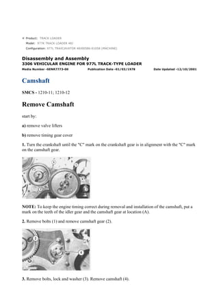
1. Product: TRACK LOADER
Model: 977K TRACK LOADER 48J
Configuration: 977L TRAXCAVATOR 48J00586-01058 (MACHINE)
Disassembly and Assembly
3306 VEHICULAR ENGINE FOR 977L TRACK-TYPE LOADER
Media Number -SENR7773-00 Publication Date -01/03/1978 Date Updated -12/10/2001
Camshaft
SMCS - 1210-11; 1210-12
Remove Camshaft
start by:
a) remove valve lifters
b) remove timing gear cover
1. Turn the crankshaft until the "C" mark on the crankshaft gear is in alignment with the "C" mark
on the camshaft gear.
NOTE: To keep the engine timing correct during removal and installation of the camshaft, put a
mark on the teeth of the idler gear and the camshaft gear at location (A).
2. Remove bolts (1) and remove camshaft gear (2).
3. Remove bolts, lock and washer (3). Remove camshaft (4).
1/2
977L TRAXCAVATOR 48J00586-01058 (MACHINE)(UEH0574S - 00) - Document...
2021/10/19
https://127.0.0.1/sisweb/sisweb/techdoc/techdoc_print_page.jsp?returnurl=/sis...
2. Install Camshaft
1. Put clean SAE 30 oil on the lobes and bearing journals of the camshaft.
2. Install camshaft (1) in the block.
3. Install washer (2), lock and bolts that hold the camshaft in place.
4. Put the camshaft gear (3) in position on the camshaft so the "C" mark on the camshaft gear is in
alignment with the "C" mark on the crankshaft gear. Install the bolts that hold the camshaft gear in
place.
NOTE: The drive gear will fit on the camshaft one way only. If necessary, turn the camshaft to
make alignment of the holes of the drive gear and the camshaft.
end by:
a) install timing gear cover
b) install valve lifters
2/2
977L TRAXCAVATOR 48J00586-01058 (MACHINE)(UEH0574S - 00) - Document...
2021/10/19
https://127.0.0.1/sisweb/sisweb/techdoc/techdoc_print_page.jsp?returnurl=/sis...
3. Product: TRACK LOADER
Model: 977K TRACK LOADER 48J
Configuration: 977L TRAXCAVATOR 48J00586-01058 (MACHINE)
Disassembly and Assembly
3306 VEHICULAR ENGINE FOR 977L TRACK-TYPE LOADER
Media Number -SENR7773-00 Publication Date -01/03/1978 Date Updated -12/10/2001
Timing Gears And Plate
SMCS - 1162-11; 1162; 1206-12; 1206
Remove Timing Gears And Plate
start by:
a) remove timing gear cover
1. Put the engine in correct timing. See REMOVE FUEL INJECTION PUMP HOUSING AND
GOVERNOR for this procedure.
2. Remove the bolt and washer that hold gear (1) and install tooling (C) on the end of the bolt.
Install and tighten the bolt, washer and tooling (C) to hold the sleeve on the end of the fuel
injection pump camshaft.
1/5
977L TRAXCAVATOR 48J00586-01058 (MACHINE)(UEH0574S - 00) - Document...
2021/10/19
https://127.0.0.1/sisweb/sisweb/techdoc/techdoc_print_page.jsp?returnurl=/sis...
4. 3. Install tooling (A) on gear (1) and tighten the center bolt of tooling (A) until gear (1) is
loosened. Remove tooling (B), the bolt, washers and gear (1).
4. Remove bolts (2), plate (4) and the idler gear (5). Remove bolts (3) and the washers to remove
gear (6) from the camshaft.
5. Inspect the bearing in idler gear (5) for wear or damage. If a replacement of the bearing is
needed, use tool group (B) to remove it from the gear as shown.
6. Remove the nuts and washers that hold the fuel injection pump housing to studs (7).
7. Remove the six bolts (8) and locks (9) that hold the timing gear plate to the cylinder block.
Remove the timing gear plate and gasket from the engine.
Install Timing Gears And Plate
2/5
977L TRAXCAVATOR 48J00586-01058 (MACHINE)(UEH0574S - 00) - Document...
2021/10/19
https://127.0.0.1/sisweb/sisweb/techdoc/techdoc_print_page.jsp?returnurl=/sis...
5. 1. Install the timing gear plate and gasket. Install the two locks and six bolts.
2. Install the three nuts and washers that hold the fuel injection pump housing to the timing gear
plate.
3. Install the camshaft drive gear. Make sure the "C" mark on the crankshaft gear is in alignment
with the "C" mark on the camshaft drive gear. Install the four washers and bolts.
4. Use tool (B) to install the bearing in the idler gear.
5. Install idler gear (2). Install plate (3) and bolts (1).
6. Put the fuel injection pump drive gear in position on the fuel system. Install the bolt and washer
that holds it finger tight only.
3/5
977L TRAXCAVATOR 48J00586-01058 (MACHINE)(UEH0574S - 00) - Document...
2021/10/19
https://127.0.0.1/sisweb/sisweb/techdoc/techdoc_print_page.jsp?returnurl=/sis...
6. TYPICAL EXAMPLE
7. Install tooling (A) in the holes of the fuel injection pump drive gear as shown. Put a torque of
approximately 50 lb.ft. (70 N·m) on the pump drive gear in a clockwise direction (as seen from
the front of the engine). With the clockwise torque on the pump drive gear tighten the bolt to a
torque of 110 ± 5 lb.ft. (149 ± 7 N·m).
end by:
a) install timing gear cover
4/5
977L TRAXCAVATOR 48J00586-01058 (MACHINE)(UEH0574S - 00) - Document...
2021/10/19
https://127.0.0.1/sisweb/sisweb/techdoc/techdoc_print_page.jsp?returnurl=/sis...
8. Product: TRACK LOADER
Model: 977K TRACK LOADER 48J
Configuration: 977L TRAXCAVATOR 48J00586-01058 (MACHINE)
Disassembly and Assembly
3306 VEHICULAR ENGINE FOR 977L TRACK-TYPE LOADER
Media Number -SENR7773-00 Publication Date -01/03/1978 Date Updated -12/10/2001
Engine And Torque Converter
SMCS - 1003-11; 1003-12
Remove Engine And Torque Converter
start by:
a) remove radiator and radiator guard
b) remove rear crankcase guards *
c) remove universal joint *
d) remove air cleaner assembly
*
These operations are in the POWER TRAIN DISASSEMBLY AND ASSEMBLY section.
1. Drain the oil from the engine.
2. Drain oil from the torque converter.
3. Drain the oil from the hydraulic tank.
4. Turn the valve for the fuel supply to the "OFF" position.
5. Remove plate assemblies (1) and floor plates (2).
1/6
977L TRAXCAVATOR 48J00586-01058 (MACHINE)(UEH0574S - 00) - Document...
2021/10/19
https://127.0.0.1/sisweb/sisweb/techdoc/techdoc_print_page.jsp?returnurl=/sis...
9. 6. Remove transmission and torque converter filter housing (3). Remove tube assembly (4).
Disconnect hose assembly (5) from the top of the hydraulic pump. Disconnect the clip that holds
the torque converter oil temperature sensing line to the torque converter.
VIEW FROM UNDER MACHINE
7. Disconnect tube assembly (7) from the hydraulic pump. Disconnect hose assembly (6) from the
torque converter inlet relief valve. Disconnect hose assembly (8) from the scavenge pump.
Disconnect tube assembly (10) from the torque converter. Remove torque converter oil
temperature sensing bulb (9) from the torque converter outlet relief valve. Remove tube assembly
(11).
8. Disconnect two heater hoses (13) and remove water temperature sensing bulb (12).
2/6
977L TRAXCAVATOR 48J00586-01058 (MACHINE)(UEH0574S - 00) - Document...
2021/10/19
https://127.0.0.1/sisweb/sisweb/techdoc/techdoc_print_page.jsp?returnurl=/sis...
10. 9. Disconnect governor control rod (14) from lever. Disconnect fuel line (15) from fuel filter base.
NOTE: Put a mark on all wires before they are removed or disconnected for installation purpose.
10. Disconnect wiring harness (16) from the electric starting motor, alternator and glow plug
wiring harness.
11. Disconnect two small tubes (19). Remove tube assemblies (17) and (18) and swivel joints.
12. Fasten a hoist to the engine. Remove bolt (20) from rear support on each side. Remove two
bolts and nuts from front support.
13. Remove the engine (21) and torque converter from the machine. Weight of the engine and
torque converter is 3000 lb. (1350 kg).
3/6
977L TRAXCAVATOR 48J00586-01058 (MACHINE)(UEH0574S - 00) - Document...
2021/10/19
https://127.0.0.1/sisweb/sisweb/techdoc/techdoc_print_page.jsp?returnurl=/sis...
11. Install Engine And Torque Converter
1. Fasten a hoist to engine (1) and torque converter (2). Put the engine and torque converter in
position on the frame of the machine.
NOTICE
Do not cause damage to any tubes, hoses or wires when the engine is
put in position.
2. Install the rear support bolts. Tighten them to a torque of 200 ± 25 lb.ft. (270 ± 35 N·m). Install
the front support bolts and nuts.
3. Install tube assemblies (3) and (4) and swivel joints. Connect two small tubes (5).
4. Connect wiring harness (7) to the electric starting motor, alternator and glow plug wiring
harness.
5. Connect fuel line (8) to the fuel filter base.
4/6
977L TRAXCAVATOR 48J00586-01058 (MACHINE)(UEH0574S - 00) - Document...
2021/10/19
https://127.0.0.1/sisweb/sisweb/techdoc/techdoc_print_page.jsp?returnurl=/sis...
12. 6. Connect governor control rod (6) to lever.
7. Install water temperature sensing bulb (9).
8. Connect two heater hoses (10).
9. Connect tube assembly (12) to the hydraulic pump. Connect hose assembly (11) to the torque
converter inlet relief valve. Connect hose assembly (13) to the scavenge pump. Connect tube
assembly (15) to the torque converter. Install torque converter oil temperature sensing bulb (14) to
the torque converter outlet relief valve. Install tube assembly (16).
10. Install transmission and torque converter filter housing (19). Install tube assembly (17) to the
torque converter and magnetic screen. Connect hose assembly (18) to the top of the hydraulic
pump. Connect the clip that holds the torque converter oil temperature sensing line to the torque
converter.
5/6
977L TRAXCAVATOR 48J00586-01058 (MACHINE)(UEH0574S - 00) - Document...
2021/10/19
https://127.0.0.1/sisweb/sisweb/techdoc/techdoc_print_page.jsp?returnurl=/sis...
13. 11. Install floor plates (21) and plate assemblies (20).
12. Turn the valve for the fuel supply to the "ON" position.
13. Fill the engine with oil to the correct level. See LUBRICATION AND MAINTENANCE
GUIDE.
14. Fill the transmission and bevel gear case with oil to the correct level. See LUBRICATION
AND MAINTENANCE GUIDE.
15. Fill the hydraulic tank with oil to the correct level. See LUBRICATION AND
MAINTENANCE GUIDE.
end by:
a) install universal joint *
b) install rear crankcase guards *
c) install radiator and radiator guard
d) install air cleaner assembly
*
These operations are in the POWER TRAIN DISASSEMBLY AND ASSEMBLY section.
6/6
977L TRAXCAVATOR 48J00586-01058 (MACHINE)(UEH0574S - 00) - Document...
2021/10/19
https://127.0.0.1/sisweb/sisweb/techdoc/techdoc_print_page.jsp?returnurl=/sis...
14. Product: TRACK LOADER
Model: 977K TRACK LOADER 48J
Configuration: 977L TRAXCAVATOR 48J00586-01058 (MACHINE)
Disassembly and Assembly
3306 VEHICULAR ENGINE FOR 977L TRACK-TYPE LOADER
Media Number -SENR7773-00 Publication Date -01/03/1978 Date Updated -12/10/2001
Flywheel
SMCS - 1156-11; 1156-12
Remove Flywheel
start by:
a remove engine and torque converter
1. Install a 5/8"-11 NC forged eyebolt to the torque converter. Fasten a hoist and remove ten bolts
(1) that hold the torque converter to the flywheel housing.
1/3
977L TRAXCAVATOR 48J00586-01058 (MACHINE)(UEH0574S - 00) - Document...
2021/10/19
https://127.0.0.1/sisweb/sisweb/techdoc/techdoc_print_page.jsp?returnurl=/sis...
15. 2. Install two 3/8"-16 NC forcing screws. Turn the forcing screws evenly until the torque
converter is free of the flywheel housing. Remove torque converter (2). Weight of the torque
converter is 450 lb. (204 kg).
3. Loosen the nine bolts that hold flywheel to the crankshaft.
4. Remove two bolts and install two 5/8"-18 NF guide bolts. Install tool (A) and remove the other
bolts. Remove flywheel (3). Weight of the flywheel is 65 lb. (29 kg).
5. Remove gear (4) from the flywheel.
Install Flywheel
1. Heat the ring gear to a maximum temperature of 600°F (316°C). Install ring gear (1) to the
flywheel.
2. Install two 5/8"-18 NF guide bolts to the flange of the crankshaft.
2/3
977L TRAXCAVATOR 48J00586-01058 (MACHINE)(UEH0574S - 00) - Document...
2021/10/19
https://127.0.0.1/sisweb/sisweb/techdoc/techdoc_print_page.jsp?returnurl=/sis...
16. 3. Use tool (A) and put flywheel (2) in position. Install the nine bolts that hold the flywheel to the
crankshaft.
4. Fasten a hoist to torque converter (3) and put it in position.
NOTE: Check the O-ring seal for damage. If the seal has damage, use a new part for replacement.
5. Install the ten bolts that hold the torque converter to the flywheel housing.
end by:
a) install engine and torque converter
3/3
977L TRAXCAVATOR 48J00586-01058 (MACHINE)(UEH0574S - 00) - Document...
2021/10/19
https://127.0.0.1/sisweb/sisweb/techdoc/techdoc_print_page.jsp?returnurl=/sis...
17. Product: TRACK LOADER
Model: 977K TRACK LOADER 48J
Configuration: 977L TRAXCAVATOR 48J00586-01058 (MACHINE)
Disassembly and Assembly
3306 VEHICULAR ENGINE FOR 977L TRACK-TYPE LOADER
Media Number -SENR7773-00 Publication Date -01/03/1978 Date Updated -12/10/2001
Crankshaft Rear Seal And Wear Sleeve
SMCS - 1161-11; 1161-12
Remove Crankshaft Rear Seal And Wear Sleeve
start by:
a) remove flywheel
NOTE: When a replacement of the rear seal is made, a replacement of the wear sleeve is to be
made also.
1. Remove the crankshaft rear seal with tool (A).
1/3
977L TRAXCAVATOR 48J00586-01058 (MACHINE)(UEH0574S - 00) - Document...
2021/10/19
https://127.0.0.1/sisweb/sisweb/techdoc/techdoc_print_page.jsp?returnurl=/sis...
18. 2. Install tool (C) in the rear seal bore.
3. Install tool (B) between tool (C) and the wear sleeve. Turn tool (B) until the edge of the tool
makes a flat place (crease) in the wear sleeve. Do this in two or more places until the wear sleeve
in loose.
4. Remove tool (C) and the wear sleeve by hand.
Install Crankshaft Rear Seal And Wear Sleeve
1. Install the crankshaft rear seal and wear sleeve with tooling (A) as follows:
a) Put locator (1) in position on the crankshaft and install the three bolts that hold it in place.
2/3
977L TRAXCAVATOR 48J00586-01058 (MACHINE)(UEH0574S - 00) - Document...
2021/10/19
https://127.0.0.1/sisweb/sisweb/techdoc/techdoc_print_page.jsp?returnurl=/sis...
19. b) Put clean engine oil on the seal lip of seal (6) and on the outside diameter of wear sleeve (2).
c) Install seal (6) on wear sleeve (2) from the end of the wear sleeve that has the bevel on the
outside diameter. Make sure the lip of the seal is toward the inside of the engine and the bevel that
is on the outside diameter of the wear sleeve is toward the outside of the engine when installed.
d) Use 8M8060 Quick Cure Primer to clean the outside diameter of the crankshaft flange (3) and
the inside diameter of wear sleeve (2).
e) Put 9S3265 Retaining Compound on the outside diameter of crankshaft flange (3) and the
inside diameter of wear sleeve (2).
NOTE: Make sure the lip of the seal is toward the inside of the engine and the outside diameter
bevel of the wear sleeve is toward the outside of the engine.
f) Put wear sleeve (2) with seal (6) on locator (1). Put installer (4) on locator (1) and install nut (5).
Put lubrication on the face of the washer and the nut.
g) Tighten nut (5) until installer (4) comes in contact with locator (1).
h) Remove tooling (A) and check the wear sleeve and seal for correct installation.
end by:
a) install flywheel
3/3
977L TRAXCAVATOR 48J00586-01058 (MACHINE)(UEH0574S - 00) - Document...
2021/10/19
https://127.0.0.1/sisweb/sisweb/techdoc/techdoc_print_page.jsp?returnurl=/sis...
20. Product: TRACK LOADER
Model: 977K TRACK LOADER 48J
Configuration: 977L TRAXCAVATOR 48J00586-01058 (MACHINE)
Disassembly and Assembly
3306 VEHICULAR ENGINE FOR 977L TRACK-TYPE LOADER
Media Number -SENR7773-00 Publication Date -01/03/1978 Date Updated -12/10/2001
Flywheel Housing
SMCS - 1157-11
Remove Flywheel Housing
start by:
a) remove flywheel
b) remove starter
1. Remove the bolts that hold the oil pan plate to the flywheel housing. Loosen the bolts that hold
the oil pan plate to the cylinder block.
2. Fasten a hoist to the engine. Lift the engine and install shims (1) on each side of the engine
between the cylinder block and the oil pan plate.
1/3
977L TRAXCAVATOR 48J00586-01058 (MACHINE)(UEH0574S - 00) - Document...
2021/10/19
https://127.0.0.1/sisweb/sisweb/techdoc/techdoc_print_page.jsp?returnurl=/sis...
21. 3. Install tool (A) to the flywheel housing. Remove the thirteen bolts that hold the flywheel
housing to the cylinder block.
4. Remove flywheel housing (2). The weight of the flywheel housing is 110 lb. (50 kg).
Install Flywheel Housing
1. Clean the old gasket from the surfaces of the cylinder block and flywheel housing that make
contact with each other. Install a new gasket on the cylinder block.
2. Install two 1/2"-13 NC guide bolts (1) in the cylinder block as shown. Install tooling (A) on the
flywheel housing. Fasten a hoist and put the flywheel housing in position on the guide bolts.
Install all but two bolts in the flywheel housing. Remove tooling (A) and the guide bolts. Install
the other two bolts.
3. Cut the bottom of the gasket even with the flywheel housing and cylinder block. Put 5H2471
Gasket Cement on the bottom of the gasket where the gasket makes contact with the gasket for the
oil pan plate. Remove shims (2) from each side of the engine. Tighten all of the oil pan bolts.
Install the bolts that hold the oil pan plate to the flywheel housing.
2/3
977L TRAXCAVATOR 48J00586-01058 (MACHINE)(UEH0574S - 00) - Document...
2021/10/19
https://127.0.0.1/sisweb/sisweb/techdoc/techdoc_print_page.jsp?returnurl=/sis...
22. end by:
a) install starting motor
b) install flywheel
3/3
977L TRAXCAVATOR 48J00586-01058 (MACHINE)(UEH0574S - 00) - Document...
2021/10/19
https://127.0.0.1/sisweb/sisweb/techdoc/techdoc_print_page.jsp?returnurl=/sis...
23. Suggest:
For more complete manuals. Please go to
the home page.
https://www.ebooklibonline.com
If the above button click is invalid. Please
download this document first, and then
click the above link to download the
complete manual.
Thank you so much for reading
24. Product: TRACK LOADER
Model: 977K TRACK LOADER 48J
Configuration: 977L TRAXCAVATOR 48J00586-01058 (MACHINE)
Disassembly and Assembly
3306 VEHICULAR ENGINE FOR 977L TRACK-TYPE LOADER
Media Number -SENR7773-00 Publication Date -01/03/1978 Date Updated -12/10/2001
Camshaft Bearings
SMCS - 1211-11; 1211-12
Remove Camshaft Bearings
start by:
a) remove oil pan plate
b) remove timing gears and plate
c) remove flywheel housing
d) remove camshaft
1. Remove the camshaft bearings with tooling (A).
Install Camshaft Bearings
1/3
977L TRAXCAVATOR 48J00586-01058 (MACHINE)(UEH0574S - 00) - Document...
2021/10/19
https://127.0.0.1/sisweb/sisweb/techdoc/techdoc_print_page.jsp?returnurl=/sis...
25. 1. Install the camshaft bearings in the cylinder block with tooling (A).
NOTE: Install all bearings with oil hole in bearing in alignment with oil hole in cylinder block.
2. The front and rear bearings are to be .06 in. (1.5 mm) inside the ends of the cylinder block after
installation.
end by:
a) install camshaft
b) install flywheel housing
c) install timing gears and plate
d) install oil pan plate
2/3
977L TRAXCAVATOR 48J00586-01058 (MACHINE)(UEH0574S - 00) - Document...
2021/10/19
https://127.0.0.1/sisweb/sisweb/techdoc/techdoc_print_page.jsp?returnurl=/sis...