
Recommended
Recommended
More Related Content
Similar to Caterpillar Cat 955K TRACK LOADER (Prefix 85J) Service Repair Manual Instant Download (85J00001-04671).pdf
Similar to Caterpillar Cat 955K TRACK LOADER (Prefix 85J) Service Repair Manual Instant Download (85J00001-04671).pdf (20)
More from ti76cui
More from ti76cui (20)
Recently uploaded
Recently uploaded (20)
Caterpillar Cat 955K TRACK LOADER (Prefix 85J) Service Repair Manual Instant Download (85J00001-04671).pdf
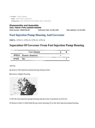
- 1. Product: TRACK LOADER Model: 955K TRACK LOADER 85J Configuration: 955K TRAXCAVATOR 85J00001-04671 (MACHINE) Disassembly and Assembly 955L TRACK-TYPE LOADER ENGINE Media Number -SENR7366-00 Publication Date -01/06/1993 Date Updated -12/10/2001 Fuel Injection Pump Housing And Governor SMCS - 1278-11; 1278-12; 1278-15; 1278-16 Separation Of Governor From Fuel Injection Pump Housing start by: a) remove fuel injection pump housing and governor b) remove adapter housing 1. Put the fuel injection pump housing and governor in position on tool (A). 2. Remove bolts (1) that hold the governor housing (2) to the fuel injection pump housing. 1/6 955K TRAXCAVATOR 85J00001-04671 (MACHINE)(UEG0008S - 00) - Document... 2021/12/15 https://127.0.0.1/sisweb/sisweb/techdoc/techdoc_print_page.jsp?returnurl=/sis...
- 2. 3. Remove governor housing (2). 4. Remove two bolts (3) from the cover. Remove cover (4) from over the torque spring. 5. Remove spring (7), wave washer (6) and guide (5) from the governor housing. 6. Remove gasket (8) from the governor housing. 7. Remove bolt (11) and nut (9) from the torque spring (10). Remove the torque spring. 8. Remove pin (12) from the hole in the fuel injection pump housing. 9. Remove seat (15) and over fueling spring (16) from the shaft. 10. Pull shaft (13) up and remove lever (14). 2/6 955K TRAXCAVATOR 85J00001-04671 (MACHINE)(UEG0008S - 00) - Document... 2021/12/15 https://127.0.0.1/sisweb/sisweb/techdoc/techdoc_print_page.jsp?returnurl=/sis...
- 3. 11. Remove riser (follower) (18) from the shaft. 12. Remove ring and lever (17) from the dowel. 13. Remove cover (19) with tool (B). NOTE: Tool (B) can cause damage to cover. Always inspect the cover for damage and install a new cover if needed. 14. Install timing pin (20) to hold the camshaft from turning. 15. Remove three bolts (21) that hold the flyweight assembly in position. 16. Remove flyweight assembly (22). 17. Remove the timing pin from the fuel injection pump housing. Connection Of Governor To Fuel Injection Pump Housing 3/6 955K TRAXCAVATOR 85J00001-04671 (MACHINE)(UEG0008S - 00) - Document... 2021/12/15 https://127.0.0.1/sisweb/sisweb/techdoc/techdoc_print_page.jsp?returnurl=/sis...
- 4. 1. Put the fuel injection pump housing on tool (A). 2. Install timing pin (1) to hold the camshaft from turning. 3. Put flyweight assembly (2) in position on the camshaft. NOTICE Make sure the pin that holds the shaft in the flyweight assembly is in position before installing the flyweight assembly. 4. Install three new bolts that hold the flyweight assembly to the camshaft. NOTE: The bolts for holding the flyweight assembly to the camshaft have a locking material on the threads. The bolts must not be used more then one time. 5. Install cover (3) over the flyweight assembly with tool (B). 6. Grind a taper on the bottom edge of a 1/8" screwdriver (4). Install the screwdriver through the bolt hole in the governor housing. The screwdriver must fit evenly against the flyweight assembly cover. Make a mark (stake) in four places around the cover in line with the groove in the camshaft. 4/6 955K TRAXCAVATOR 85J00001-04671 (MACHINE)(UEG0008S - 00) - Document... 2021/12/15 https://127.0.0.1/sisweb/sisweb/techdoc/techdoc_print_page.jsp?returnurl=/sis...
- 5. NOTICE Never install a used flyweight cover. 7. Put lever (7) on the dowel. Install ring (6). 8. Install pin (5) in the fuel injection pump housing with the round edge down. 9. Put the riser (follower) (11) in position between the flyweights. Lift the flyweights up with a piece of wire and push the riser (follower) forward. 10. Put lever (10) in position in the groove of the riser (follower) (11) and the ball end engaged in the sleeve shaft lever (8). Install shaft (9) that holds the lever in position. NOTICE If lever (10) is not installed correctly, the governor can not operate and can cause the engine to overspeed. 5/6 955K TRAXCAVATOR 85J00001-04671 (MACHINE)(UEG0008S - 00) - Document... 2021/12/15 https://127.0.0.1/sisweb/sisweb/techdoc/techdoc_print_page.jsp?returnurl=/sis...
- 6. 11. Install over fueling spring (14) and seat (13) on the shaft. 12. Install the torque spring (12). Install the bolt and nut that hold the torque spring in position. 13. Install guide (18), wave washer (16) and spring (17) in the governor housing. 14. Put a new gasket (15) on the governor housing. 15. Install cover (19) over the torque spring. Install the two bolts that hold the cover in position. 16. Put the governor housing on the fuel injection pump housing. Install the bolts that hold the governor housing in position. end by: a) install adapter housing b) install fuel injection pump housing and governor 6/6 955K TRAXCAVATOR 85J00001-04671 (MACHINE)(UEG0008S - 00) - Document... 2021/12/15 https://127.0.0.1/sisweb/sisweb/techdoc/techdoc_print_page.jsp?returnurl=/sis...
- 7. Product: TRACK LOADER Model: 955K TRACK LOADER 85J Configuration: 955K TRAXCAVATOR 85J00001-04671 (MACHINE) Disassembly and Assembly 955L TRACK-TYPE LOADER ENGINE Media Number -SENR7366-00 Publication Date -01/06/1993 Date Updated -12/10/2001 Governor SMCS - 1264-15; 1264-16 Disassemble Governor start by: a) separation of governor from fuel injection pump housing 1. Remove shaft (2). Remove pin (1) from the shaft. 2. Remove pins (3) from the flyweights. Remove flyweights (4). 3. Remove ring, races (6) and bearings from the riser (follower) (5). NOTE: There is a force on the cover (7) from the spring (8). 1/6 955K TRAXCAVATOR 85J00001-04671 (MACHINE)(UEG0008S - 00) - Document... 2021/12/15 https://127.0.0.1/sisweb/sisweb/techdoc/techdoc_print_page.jsp?returnurl=/sis...
- 8. 4. Remove cover (7) and spring (8) from the governor housing. 5. Remove seal (9) from the cover. 6. Remove cover (10) for the low and high idle adjustments. 7. Remove locknut and screw (13) for the high idle adjustment. 8. Remove bolt (15) and washers for the low idle adjustment. 9. Remove spring (16) and guide. 10. Remove pin (14) and plate (11). 11. Remove shaft (12) from the housing. 12. Remove pin (18) and two spacers (17) from the shaft. NOTE: Earlier model sleeve metering fuel systems have a ball in place of spacers (17) and pin (18). 2/6 955K TRAXCAVATOR 85J00001-04671 (MACHINE)(UEG0008S - 00) - Document... 2021/12/15 https://127.0.0.1/sisweb/sisweb/techdoc/techdoc_print_page.jsp?returnurl=/sis...
- 9. 13. Remove shaft (19) from the governor housing. 14. Remove washer (20) and levers (21) and (22) from the governor housing. 15. Remove seal (24) and bearing. 16. Remove seals (23) and (25) from the governor housing. Assemble Governor 1. Install the bearing and seal in the housing with tool (A). The lip of the seal must be toward the bearing. 2. Install seal (1) in the housing with tool (A). The lip of the seal must be toward the inside of the housing. 3/6 955K TRAXCAVATOR 85J00001-04671 (MACHINE)(UEG0008S - 00) - Document... 2021/12/15 https://127.0.0.1/sisweb/sisweb/techdoc/techdoc_print_page.jsp?returnurl=/sis...
- 10. 3. Install seal (2) in the housing with tooling (B). The lip of the seal must be toward the inside of the housing. 4. Install shaft (3) in the housing. 5. Install plates (4), spacers (8) and pin (7) on the shaft. 6. Install shaft (5) in the housing and through washer (9) and levers (6). 7. Install pin (11) in holes of the plates. 8. Install screw (10) and locknut for high idle adjustment. 9. Install spring (13) and guide. 10. Install bolts (12) and washer for low idle adjustment. 11. Push plate and pin (11) over toward bolt (12) and tighten the bolt. 12. Install the seal in the cover with tooling (B). The lip of the seal must be toward the inside. 4/6 955K TRAXCAVATOR 85J00001-04671 (MACHINE)(UEG0008S - 00) - Document... 2021/12/15 https://127.0.0.1/sisweb/sisweb/techdoc/techdoc_print_page.jsp?returnurl=/sis...
- 11. 13. Install spring (15) in the cover. NOTICE The spring (15) must be installed with the end of the spring as shown. 14. Install the cover (16) for the idle adjustment screws. 15. Install bearing (19) between races (18) on riser (follower) (17). Install ring (20) that holds the washer on the riser (follower). 5/6 955K TRAXCAVATOR 85J00001-04671 (MACHINE)(UEG0008S - 00) - Document... 2021/12/15 https://127.0.0.1/sisweb/sisweb/techdoc/techdoc_print_page.jsp?returnurl=/sis...
- 12. 16. Install pin in shaft (23). 17. Install flyweights (22) and pin (21). 18. Install shaft (23) in flyweight assembly. end by: a) connection of governor to fuel injection pump housing 6/6 955K TRAXCAVATOR 85J00001-04671 (MACHINE)(UEG0008S - 00) - Document... 2021/12/15 https://127.0.0.1/sisweb/sisweb/techdoc/techdoc_print_page.jsp?returnurl=/sis...
- 13. Product: TRACK LOADER Model: 955K TRACK LOADER 85J Configuration: 955K TRAXCAVATOR 85J00001-04671 (MACHINE) Disassembly and Assembly 955L TRACK-TYPE LOADER ENGINE Media Number -SENR7366-00 Publication Date -01/06/1993 Date Updated -12/10/2001 Fuel Check Valve And Bypass Valve SMCS - 1264-15; 1264-16 Remove Fuel Check Valve And Bypass Valve NOTICE Clean the outer surface of the fuel injection pump housing and governor before removing the fuel check valve and bypass valve. 1. Remove the fuel from the fuel injection pump housing. Install the fuel injection pump housing and governor on tool (A). 2. Remove eight bolts (2). Remove cover (1). 3. Remove check valve (3). 1/2 955K TRAXCAVATOR 85J00001-04671 (MACHINE)(UEG0008S - 00) - Document... 2021/12/15 https://127.0.0.1/sisweb/sisweb/techdoc/techdoc_print_page.jsp?returnurl=/sis...
- 14. 4. Remove spring (4) and the bypass valve. Install Fuel Check Valve And Bypass Valve 1. Install bypass valve (2) and spring (1) in the fuel injection pump housing. 2. Install check valve (3) in the fuel injection pump housing. Make sure the check valve is installed evenly in the fuel injection pump housing. NOTE: Do not install a check valve that is bent. 3. Put the cover in position on the fuel injection pump housing. Make sure the spring on the bypass valve is in the cover. Install the eight bolts that hold the cover in position. 2/2 955K TRAXCAVATOR 85J00001-04671 (MACHINE)(UEG0008S - 00) - Document... 2021/12/15 https://127.0.0.1/sisweb/sisweb/techdoc/techdoc_print_page.jsp?returnurl=/sis...
- 15. Product: TRACK LOADER Model: 955K TRACK LOADER 85J Configuration: 955K TRAXCAVATOR 85J00001-04671 (MACHINE) Disassembly and Assembly 955L TRACK-TYPE LOADER ENGINE Media Number -SENR7366-00 Publication Date -01/06/1993 Date Updated -12/10/2001 Fuel Injection Pumps SMCS - 1251-15; 1251-16; 1251-11; 1251-12 Remove Fuel Injection Pumps NOTICE Before any service work is to be done on the fuel system the outer surface of injection pump housing must be clean. 1. Remove the cover assembly (1) from the pump housing. Remove spring for the bypass valve. 1/4 955K TRAXCAVATOR 85J00001-04671 (MACHINE)(UEG0008S - 00) - Document... 2021/12/15 https://127.0.0.1/sisweb/sisweb/techdoc/techdoc_print_page.jsp?returnurl=/sis...
- 16. 2. Loosen the bushing (2) from the pump housing with tool (A). NOTE: Do not loosen the screws (3) that hold levers to shaft when the pumps are removed or installed. If levers are moved, fuel pump adjustment will be changed. 3. Remove the fuel injection pump from the pump housing. The sleeve on the plunger will slide off the lever as the pump is removed. Install Fuel Injection Pumps 1. Put the fuel injection pump (1) in the bore of pump housing. 2. The sleeve (2) will be engaged with lever when installed correctly. NOTICE If levers have been moved on the shaft, fuel pump adjustment must be made. (See TESTING AND ADJUSTING). 3. Tighten the bushing with wrench (A) to a torque of 70 ± 5 lb. ft. (94.9 ± 6.8 N·m). 4. Put the spring on the bypass valve. Install the cover assembly on the pump housing. Be sure the spring (3) is in position in the cover. Disassemble Fuel Injection Pumps 2/4 955K TRAXCAVATOR 85J00001-04671 (MACHINE)(UEG0008S - 00) - Document... 2021/12/15 https://127.0.0.1/sisweb/sisweb/techdoc/techdoc_print_page.jsp?returnurl=/sis...
- 17. start by: a) remove fuel injection pumps 1. Remove the bushing (1) from the bonnet (2). 2. Remove the ring (3) from the bonnet and barrel (7). Remove the check valve (6) and spring (4) from the bonnet. 3. Remove the spring (8) and washer (5). Remove the plunger (9) and sleeve (10). NOTE: Keep the plunger and sleeve with their respective barrel for installation. Do not use plungers, sleeves, and barrels with other plungers, sleeves, and barrels. Assemble Fuel Injection Pumps 3/4 955K TRAXCAVATOR 85J00001-04671 (MACHINE)(UEG0008S - 00) - Document... 2021/12/15 https://127.0.0.1/sisweb/sisweb/techdoc/techdoc_print_page.jsp?returnurl=/sis...
- 18. 1. Install the sleeve (4), plunger (5), spring (2), and washer (3) on the barrel (1). NOTE: Be sure sleeve and plunger are installed in original barrel, and large hole in plunger is up. 2. Install check valve and spring in bonnet. Connect the barrel and bonnet and install the ring. Install the bushing on the bonnet. end by: a) install fuel injection pumps 4/4 955K TRAXCAVATOR 85J00001-04671 (MACHINE)(UEG0008S - 00) - Document... 2021/12/15 https://127.0.0.1/sisweb/sisweb/techdoc/techdoc_print_page.jsp?returnurl=/sis...
- 19. Product: TRACK LOADER Model: 955K TRACK LOADER 85J Configuration: 955K TRAXCAVATOR 85J00001-04671 (MACHINE) Disassembly and Assembly 955L TRACK-TYPE LOADER ENGINE Media Number -SENR7366-00 Publication Date -01/06/1993 Date Updated -12/10/2001 Fuel Transfer Pump SMCS - 1256-11; 1256-12 Remove Fuel Transfer Pump 1. Put the fuel injection pump housing on tool (A). 2. Install timing pin (1) to keep the injection pump camshaft in position when the transfer pump is removed. 3. Install bolt (B) in the threads of sleeve (4). Tighten the bolt until the sleeve can be removed. NOTICE 1/5 955K TRAXCAVATOR 85J00001-04671 (MACHINE)(UEG0008S - 00) - Document... 2021/12/15 https://127.0.0.1/sisweb/sisweb/techdoc/techdoc_print_page.jsp?returnurl=/sis...
- 20. Do not hit the bolt or sleeve. This will cause damage to the unit. 4. Remove bolts (3) that hold the body to the housing. 5. Remove body (2) from the housing. 6. Remove idler gear (6) from the body. 7. Remove O-ring seal (5) and the two lip-type seals from the body. 8. Remove drive gear (7) from the shaft. 9. Remove key (8) from the shaft. Install Fuel Transfer Pump 2/5 955K TRAXCAVATOR 85J00001-04671 (MACHINE)(UEG0008S - 00) - Document... 2021/12/15 https://127.0.0.1/sisweb/sisweb/techdoc/techdoc_print_page.jsp?returnurl=/sis...
- 21. 1. Install the inner seal in the body with tool (A). The lip of the seal must be toward the pump gears. 2. Install the outer seal with tool (B). The lip of the seal must be toward the outside. NOTICE Always be careful not to cause damage to the machined surface of the pump body. 3. Install the O-ring seal (2) and the idler gear (1) on the body. 4. Install the key and drive gear (3) on the shaft. 3/5 955K TRAXCAVATOR 85J00001-04671 (MACHINE)(UEG0008S - 00) - Document... 2021/12/15 https://127.0.0.1/sisweb/sisweb/techdoc/techdoc_print_page.jsp?returnurl=/sis...
- 22. 5. Install the body (4) on the housing. 6. Install the bolts that hold the body to the housing. 7. Put the sleeve (5) in position on the camshaft. NOTE: The timing pin must be in the position shown to keep the camshaft in position when the transfer pump is installed. 8. Install the sleeve on the camshaft with tooling (C). NOTICE Do not hit the sleeve with a hammer to install it. This will put end force on the camshaft and cause damage to the other components in the pump housing. 4/5 955K TRAXCAVATOR 85J00001-04671 (MACHINE)(UEG0008S - 00) - Document... 2021/12/15 https://127.0.0.1/sisweb/sisweb/techdoc/techdoc_print_page.jsp?returnurl=/sis...
- 23. 9. The end clearance of the camshaft must be .023 ± .018 in. (0.58 ± 0.46 mm) after sleeve (5) is installed. end by: a) install fuel injection pump housing and governor 5/5 955K TRAXCAVATOR 85J00001-04671 (MACHINE)(UEG0008S - 00) - Document... 2021/12/15 https://127.0.0.1/sisweb/sisweb/techdoc/techdoc_print_page.jsp?returnurl=/sis...
- 24. Suggest: For more complete manuals. Please go to the home page. https://www.ebooklibonline.com If the above button click is invalid. Please download this document first, and then click the above link to download the complete manual. Thank you so much for reading
- 25. Product: TRACK LOADER Model: 955K TRACK LOADER 85J Configuration: 955K TRAXCAVATOR 85J00001-04671 (MACHINE) Disassembly and Assembly 955L TRACK-TYPE LOADER ENGINE Media Number -SENR7366-00 Publication Date -01/06/1993 Date Updated -12/10/2001 Fuel Injection Pump Housing SMCS - 1253-15; 1253-16 Disassemble Fuel Injection Pump Housing start by: a) remove fuel injection pumps b) separation of governor from fuel injection pump housing c) remove fuel transfer pump 1. Remove the dowel from the fuel injection pump housing for the torque spring lever. 1/3 955K TRAXCAVATOR 85J00001-04671 (MACHINE)(UEG0008S - 00) - Document... 2021/12/15 https://127.0.0.1/sisweb/sisweb/techdoc/techdoc_print_page.jsp?returnurl=/sis...
- 26. 2. Loosen the screws that hold levers (1) to the sleeve control shaft (2). 3. Remove the sleeve control shaft (2) from the fuel injection pump housing. 4. Remove lifters and roller assemblies (3) from the fuel injection pump housing. NOTE: Put identification on the lifters and rollers so they will not be mixed at assembly. 5. Remove the camshaft from the fuel injection pump housing. Assemble Fuel Injection Pump Housing 2/3 955K TRAXCAVATOR 85J00001-04671 (MACHINE)(UEG0008S - 00) - Document... 2021/12/15 https://127.0.0.1/sisweb/sisweb/techdoc/techdoc_print_page.jsp?returnurl=/sis...