The document provides step-by-step instructions for disassembling and assembling the transmission and transfer gears of a 977K track loader. It details removing over 30 individual components in the disassembly process, including the transmission case, selector valve, bearings, and input shaft. Reassembly requires properly cleaning and replacing seals on each part before reinstalling the components in the reverse order of disassembly.
The document provides instructions for disassembling and assembling various components of a Caterpillar 3306 vehicular engine used in a 977L track loader, including:
- Removing and installing the camshaft, following marks to ensure proper timing
- Removing and installing timing gears and plate, using tools to apply torque for proper installation
- Removing the engine and torque converter by disconnecting hoses, wires, and supports, and reinstalling by reversing the process
- Removing and installing the flywheel by loosening bolts, using tools and heat treatment, and reinstalling by reversing the process
The document provides instructions for disassembling and assembling various components of a Caterpillar 3306 vehicular engine used in a 977L track loader, including:
- Removing and installing the camshaft, following marks to maintain proper timing.
- Removing and installing timing gears and plate, using tools to apply torque and ensure proper alignment.
- Removing the engine and torque converter by disconnecting hoses, wires, and supports, and reinstalling by reversing the process.
- Removing the flywheel by loosening bolts and installing guide bolts, and reinstalling it along with heating and installing the ring gear.
The document provides instructions for disassembling and assembling various components of a Caterpillar 3306 vehicular engine used in a 977L track loader, including:
- Removing and installing the camshaft, following marks to ensure proper timing
- Removing and installing timing gears and plate, using tools to apply torque for correct installation
- Removing the engine and torque converter by disconnecting hoses, wires, and supports, and reinstalling by reversing the process
- Removing and installing the flywheel by loosening bolts, using tools and heat treatment, and reinstalling by reversing the process
The document provides instructions for disassembling and assembling various components of a 955K track loader engine, including:
1) Separating and reconnecting the governor from the fuel injection pump housing.
2) Disassembling and reassembling the governor.
3) Removing and installing the fuel check valve and bypass valve.
4) Taking out and putting in the fuel injection pumps.
5) Taking apart and rebuilding the fuel injection pumps.
1. The document provides instructions for disassembling and assembling various components of a 955K track loader engine, including the governor, fuel injection pumps, fuel check valve, and bypass valve.
2. Steps are provided to separate the governor from the fuel injection pump housing, disassemble the governor, remove and install the fuel check valve and bypass valve, remove and install the fuel injection pumps, and disassemble and assemble the fuel injection pumps.
3. Cleaning procedures and special notes are included throughout to ensure correct assembly.
The document provides instructions for disassembling and assembling various components of a 955K track loader engine, including:
1) Separating and reconnecting the governor from the fuel injection pump housing.
2) Disassembling and assembling the governor.
3) Removing and installing the fuel check valve and bypass valve.
The instructions are presented in a step-by-step format with pictures to aid in the process. Proper installation of parts is emphasized to ensure correct engine operation.
Caterpillar cat 322 l track excavator (prefix 7wl) service repair manual (7wl...fjjsekkksmeik
The document provides instructions for removing and installing final drive sprockets, travel brake valves, and travel motors on a 322-A excavator model. Key steps include separating the track assemblies, using tools to support heavy components like the sprocket while removing fasteners, cleaning mating surfaces, replacing seals, and torquing fasteners to the specified values. The instructions note safety precautions and contain diagrams to illustrate the procedures.
Caterpillar cat 322 l track excavator (prefix 7wl) service repair manual (7wl...fjjskkemsmee
This document provides instructions for removing and installing final drive sprockets and travel brake valves on a 322-A excavator. It describes using tools to support the sprocket and brake valve during removal to avoid injury. The steps include releasing hydraulic pressure, removing mounting bolts and hoisting out the heavy components. Reinstallation involves cleaning mating surfaces, checking seals, applying thread lock and torqueing fasteners to the specified values.
The document provides instructions for disassembling and assembling various components of a Caterpillar 3306 vehicular engine used in a 977L track loader, including:
- Removing and installing the camshaft, following marks to ensure proper timing
- Removing and installing timing gears and plate, using tools to apply torque for proper installation
- Removing the engine and torque converter by disconnecting hoses, wires, and supports, and reinstalling by reversing the process
- Removing and installing the flywheel by loosening bolts, using tools and heat treatment, and reinstalling by reversing the process
The document provides instructions for disassembling and assembling various components of a Caterpillar 3306 vehicular engine used in a 977L track loader, including:
- Removing and installing the camshaft, following marks to maintain proper timing.
- Removing and installing timing gears and plate, using tools to apply torque and ensure proper alignment.
- Removing the engine and torque converter by disconnecting hoses, wires, and supports, and reinstalling by reversing the process.
- Removing the flywheel by loosening bolts and installing guide bolts, and reinstalling it along with heating and installing the ring gear.
The document provides instructions for disassembling and assembling various components of a Caterpillar 3306 vehicular engine used in a 977L track loader, including:
- Removing and installing the camshaft, following marks to ensure proper timing
- Removing and installing timing gears and plate, using tools to apply torque for correct installation
- Removing the engine and torque converter by disconnecting hoses, wires, and supports, and reinstalling by reversing the process
- Removing and installing the flywheel by loosening bolts, using tools and heat treatment, and reinstalling by reversing the process
The document provides instructions for disassembling and assembling various components of a 955K track loader engine, including:
1) Separating and reconnecting the governor from the fuel injection pump housing.
2) Disassembling and reassembling the governor.
3) Removing and installing the fuel check valve and bypass valve.
4) Taking out and putting in the fuel injection pumps.
5) Taking apart and rebuilding the fuel injection pumps.
1. The document provides instructions for disassembling and assembling various components of a 955K track loader engine, including the governor, fuel injection pumps, fuel check valve, and bypass valve.
2. Steps are provided to separate the governor from the fuel injection pump housing, disassemble the governor, remove and install the fuel check valve and bypass valve, remove and install the fuel injection pumps, and disassemble and assemble the fuel injection pumps.
3. Cleaning procedures and special notes are included throughout to ensure correct assembly.
The document provides instructions for disassembling and assembling various components of a 955K track loader engine, including:
1) Separating and reconnecting the governor from the fuel injection pump housing.
2) Disassembling and assembling the governor.
3) Removing and installing the fuel check valve and bypass valve.
The instructions are presented in a step-by-step format with pictures to aid in the process. Proper installation of parts is emphasized to ensure correct engine operation.
Caterpillar cat 322 l track excavator (prefix 7wl) service repair manual (7wl...fjjsekkksmeik
The document provides instructions for removing and installing final drive sprockets, travel brake valves, and travel motors on a 322-A excavator model. Key steps include separating the track assemblies, using tools to support heavy components like the sprocket while removing fasteners, cleaning mating surfaces, replacing seals, and torquing fasteners to the specified values. The instructions note safety precautions and contain diagrams to illustrate the procedures.
Caterpillar cat 322 l track excavator (prefix 7wl) service repair manual (7wl...fjjskkemsmee
This document provides instructions for removing and installing final drive sprockets and travel brake valves on a 322-A excavator. It describes using tools to support the sprocket and brake valve during removal to avoid injury. The steps include releasing hydraulic pressure, removing mounting bolts and hoisting out the heavy components. Reinstallation involves cleaning mating surfaces, checking seals, applying thread lock and torqueing fasteners to the specified values.
The document provides instructions for removing and installing final drive sprockets, travel brake valves, and travel motors on a 322-A excavator model. Key steps include separating the track assemblies, using tools to support heavy components like the sprocket while removing fasteners, cleaning mating surfaces, replacing seals, and torquing fasteners to the specified values. The process also requires draining oil from the final drive and relieving hydraulic pressure before disconnecting any lines.
The document provides instructions for removing and installing final drive sprockets, travel brake valves, and travel motors on a 322-A excavator model. Key steps include separating the track assemblies, using tools to support heavy components like the sprocket while removing fasteners, cleaning mating surfaces, replacing seals, and torquing fasteners to the specified values. The instructions note safety precautions and proper procedures to contain fluids.
This document provides instructions for removing and installing final drive sprockets and travel brake valves on a 322-A excavator. It describes using tools to support the sprocket and brake valve during removal to avoid injury. The steps include releasing hydraulic pressure, removing mounting bolts and hoisting out the heavy components. Reinstallation involves cleaning parts, checking seals, applying thread lock and torqueing fasteners to the specified values.
This document provides instructions for removing and installing final drive sprockets and travel brake valves on a 322-A excavator. It describes using tools to support the sprocket and valve during removal to avoid injury. Steps include cleaning parts, checking seals, applying thread lock and torqueing fasteners to specified values.
The document provides instructions for removing and installing final drive sprockets, travel brake valves, and travel motors on a 322-A excavator model. Key steps include separating the track assemblies, using tools to support heavy components like the sprocket while removing fasteners, cleaning mating surfaces, replacing seals, and torquing fasteners to the specified values. The process also involves draining oil from the final drive and hydraulic system before removing components.
This document provides instructions for removing and installing final drive sprockets and travel brake valves on a 322-A excavator. It describes using tools to support the sprocket and brake valve during removal to avoid injury. The steps include releasing hydraulic pressure, removing mounting bolts and hoisting out the heavy components. Reinstallation involves cleaning mating surfaces, checking seals, applying thread lock and torqueing fasteners to the specified values.
This document provides instructions for removing and installing final drive sprockets and travel brake valves on a 322-A excavator. It describes using tools to support the sprocket and brake valve during removal to avoid injury. The steps include releasing hydraulic pressure, removing mounting bolts and hoisting out the heavy components. Reinstallation involves cleaning parts, checking seals, applying thread lock and torqueing fasteners to the specified values.
The document provides instructions for removing and installing final drive sprockets, travel brake valves, and travel motors on a 322-A excavator model. It describes disconnecting hydraulic lines, draining oil, and removing bolts and components. Detailed cleaning and installation steps are listed, including applying thread lock and torquing bolts to the specified values.
The document provides instructions for removing and installing final drive sprockets, travel brake valves, and travel motors on a 322-A excavator model. It describes disconnecting hydraulic lines, draining oil, and removing bolts and components. Detailed cleaning and installation steps are listed, including applying thread lock and tightening bolts to specified torques. Safety notices are included to contain fluids and release pressure before disconnection.
The document provides instructions for removing and installing final drive sprockets, travel brake valves, and travel motors on a 322-A excavator model. Key steps include separating the track assemblies, using tools to support heavy components like the sprocket while removing fasteners, cleaning mating surfaces, replacing seals, and torquing fasteners to the specified values. The process also requires draining oil from the final drive before removing certain components.
The document provides instructions for removing and installing final drive sprockets, travel brake valves, and travel motors on a 322-A excavator model. Key steps include separating the track assemblies, using tools to support heavy components like the sprocket while removing fasteners, cleaning mating surfaces, replacing seals, and torquing fasteners to the specified values. The process also requires draining oil from the final drive and hydraulic system before removing components.
This document provides instructions for removing and installing final drive sprockets and travel brake valves on a 322-A excavator. It describes using tools to support the sprocket and brake valve during removal to avoid injury. The steps include releasing hydraulic pressure, removing mounting bolts and hoisting out the heavy components. Reinstallation involves cleaning parts, checking seals, applying thread lock and torqueing fasteners to the specified values.
This document provides instructions for removing and installing final drive sprockets and travel brake valves on a 322-A excavator. It outlines the necessary safety procedures and gives step-by-step instructions for each job. To remove a final drive sprocket, tools must be installed under the frame and 16 bolts removed to lift the sprocket off. Travel brake valves are removed by releasing hydraulic pressure, disconnecting pipes, and removing 6 bolts. Detailed cleaning and installation steps are provided for both components.
The document provides instructions for removing and installing final drive sprockets, travel brake valves, and travel motors on a 322-A excavator model. It describes disconnecting hydraulic lines, draining oil, and removing bolts and components. Detailed cleaning and installation steps are listed, including applying thread lock and torquing bolts to the specified values. Tools needed and safety precautions are also outlined.
The document provides instructions for removing and installing final drive sprockets, travel brake valves, and travel motors on a 322-A excavator model. Key steps include separating the track assemblies, using tools to support heavy components like the sprocket while removing fasteners, cleaning mating surfaces, replacing seals, and torquing fasteners to the specified values. The process also requires draining oil from the final drive and hydraulic system before removing components.
This document provides instructions for removing and installing final drive sprockets and travel brake valves on a 322-A excavator. It describes using tools to support the sprocket and brake valve during removal to avoid injury. The steps include releasing hydraulic pressure, removing mounting bolts and hoisting out the heavy components. Reinstallation involves cleaning mating surfaces, checking seals, applying thread lock and torqueing fasteners to the specified values.
The document provides instructions for removing and installing final drive sprockets, travel brake valves, and travel motors on a 322-A excavator model. It describes disconnecting hydraulic lines, draining oil, and removing bolts and components. Detailed cleaning and installation steps are listed, including applying thread lock and torquing bolts to the specified values.
The document provides instructions for removing and installing final drive sprockets, travel brake valves, and travel motors on a 322-A excavator model. Key steps include separating the track assemblies, using tools to support heavy components like the sprocket while removing fasteners, cleaning mating surfaces, replacing seals, and torquing fasteners to the specified values. The process also requires draining oil from the final drive before removing certain components.
The document provides instructions for removing and installing final drive sprockets, travel brake valves, and travel motors on a 322-A excavator model. Key steps include separating the track assemblies, using tools to support heavy components like the sprocket while removing fasteners, cleaning mating surfaces, replacing seals, and torquing fasteners to the specified values. The instructions note safety precautions and contain diagrams to illustrate the procedures.
This document provides instructions for disassembling and assembling the governor component of a Caterpillar 3204 vehicular engine. It describes removing and installing various parts of the governor including the housing, lever assembly, springs, and weight assembly. The instructions note to clean and oil parts during reassembly. It concludes by stating to adjust the rack and governor after reinstalling the fuel injection pump housing and governor.
Caterpillar Cat TH460B Telehandler (Prefix SLF) Service Repair Manual Instant...ting1499041267
This document provides instructions for removing and installing various engine components on a Caterpillar 3054E engine, including the cylinder head, rocker shaft, lifters, and camshaft. The procedures describe cleaning parts, lubricating bolts, and torquing fasteners to the specified values. Special tools may be required for some steps.
Caterpillar Cat TH350B Telehandler (Prefix SLD) Service Repair Manual Instant...ting1499041267
This document provides instructions for removing and installing the valve mechanism cover on a 3054E engine. It describes:
1) Disconnecting the breather hose and removing nuts and washers to take off the valve cover, gasket and seal.
2) Inspecting the valve cover, gasket surfaces, and replacing worn parts before reinstallation.
3) Reinstalling the valve cover using a new gasket and seal, and reconnecting the breather hose. Tightening the nuts in a sequence is specified.
More Related Content
Similar to Caterpillar Cat 977K 977L TRACK LOADER (Prefix 11K) Service Repair Manual Instant Download (11K05051-07762).pdf
The document provides instructions for removing and installing final drive sprockets, travel brake valves, and travel motors on a 322-A excavator model. Key steps include separating the track assemblies, using tools to support heavy components like the sprocket while removing fasteners, cleaning mating surfaces, replacing seals, and torquing fasteners to the specified values. The process also requires draining oil from the final drive and relieving hydraulic pressure before disconnecting any lines.
The document provides instructions for removing and installing final drive sprockets, travel brake valves, and travel motors on a 322-A excavator model. Key steps include separating the track assemblies, using tools to support heavy components like the sprocket while removing fasteners, cleaning mating surfaces, replacing seals, and torquing fasteners to the specified values. The instructions note safety precautions and proper procedures to contain fluids.
This document provides instructions for removing and installing final drive sprockets and travel brake valves on a 322-A excavator. It describes using tools to support the sprocket and brake valve during removal to avoid injury. The steps include releasing hydraulic pressure, removing mounting bolts and hoisting out the heavy components. Reinstallation involves cleaning parts, checking seals, applying thread lock and torqueing fasteners to the specified values.
This document provides instructions for removing and installing final drive sprockets and travel brake valves on a 322-A excavator. It describes using tools to support the sprocket and valve during removal to avoid injury. Steps include cleaning parts, checking seals, applying thread lock and torqueing fasteners to specified values.
The document provides instructions for removing and installing final drive sprockets, travel brake valves, and travel motors on a 322-A excavator model. Key steps include separating the track assemblies, using tools to support heavy components like the sprocket while removing fasteners, cleaning mating surfaces, replacing seals, and torquing fasteners to the specified values. The process also involves draining oil from the final drive and hydraulic system before removing components.
This document provides instructions for removing and installing final drive sprockets and travel brake valves on a 322-A excavator. It describes using tools to support the sprocket and brake valve during removal to avoid injury. The steps include releasing hydraulic pressure, removing mounting bolts and hoisting out the heavy components. Reinstallation involves cleaning mating surfaces, checking seals, applying thread lock and torqueing fasteners to the specified values.
This document provides instructions for removing and installing final drive sprockets and travel brake valves on a 322-A excavator. It describes using tools to support the sprocket and brake valve during removal to avoid injury. The steps include releasing hydraulic pressure, removing mounting bolts and hoisting out the heavy components. Reinstallation involves cleaning parts, checking seals, applying thread lock and torqueing fasteners to the specified values.
The document provides instructions for removing and installing final drive sprockets, travel brake valves, and travel motors on a 322-A excavator model. It describes disconnecting hydraulic lines, draining oil, and removing bolts and components. Detailed cleaning and installation steps are listed, including applying thread lock and torquing bolts to the specified values.
The document provides instructions for removing and installing final drive sprockets, travel brake valves, and travel motors on a 322-A excavator model. It describes disconnecting hydraulic lines, draining oil, and removing bolts and components. Detailed cleaning and installation steps are listed, including applying thread lock and tightening bolts to specified torques. Safety notices are included to contain fluids and release pressure before disconnection.
The document provides instructions for removing and installing final drive sprockets, travel brake valves, and travel motors on a 322-A excavator model. Key steps include separating the track assemblies, using tools to support heavy components like the sprocket while removing fasteners, cleaning mating surfaces, replacing seals, and torquing fasteners to the specified values. The process also requires draining oil from the final drive before removing certain components.
The document provides instructions for removing and installing final drive sprockets, travel brake valves, and travel motors on a 322-A excavator model. Key steps include separating the track assemblies, using tools to support heavy components like the sprocket while removing fasteners, cleaning mating surfaces, replacing seals, and torquing fasteners to the specified values. The process also requires draining oil from the final drive and hydraulic system before removing components.
This document provides instructions for removing and installing final drive sprockets and travel brake valves on a 322-A excavator. It describes using tools to support the sprocket and brake valve during removal to avoid injury. The steps include releasing hydraulic pressure, removing mounting bolts and hoisting out the heavy components. Reinstallation involves cleaning parts, checking seals, applying thread lock and torqueing fasteners to the specified values.
This document provides instructions for removing and installing final drive sprockets and travel brake valves on a 322-A excavator. It outlines the necessary safety procedures and gives step-by-step instructions for each job. To remove a final drive sprocket, tools must be installed under the frame and 16 bolts removed to lift the sprocket off. Travel brake valves are removed by releasing hydraulic pressure, disconnecting pipes, and removing 6 bolts. Detailed cleaning and installation steps are provided for both components.
The document provides instructions for removing and installing final drive sprockets, travel brake valves, and travel motors on a 322-A excavator model. It describes disconnecting hydraulic lines, draining oil, and removing bolts and components. Detailed cleaning and installation steps are listed, including applying thread lock and torquing bolts to the specified values. Tools needed and safety precautions are also outlined.
The document provides instructions for removing and installing final drive sprockets, travel brake valves, and travel motors on a 322-A excavator model. Key steps include separating the track assemblies, using tools to support heavy components like the sprocket while removing fasteners, cleaning mating surfaces, replacing seals, and torquing fasteners to the specified values. The process also requires draining oil from the final drive and hydraulic system before removing components.
This document provides instructions for removing and installing final drive sprockets and travel brake valves on a 322-A excavator. It describes using tools to support the sprocket and brake valve during removal to avoid injury. The steps include releasing hydraulic pressure, removing mounting bolts and hoisting out the heavy components. Reinstallation involves cleaning mating surfaces, checking seals, applying thread lock and torqueing fasteners to the specified values.
The document provides instructions for removing and installing final drive sprockets, travel brake valves, and travel motors on a 322-A excavator model. It describes disconnecting hydraulic lines, draining oil, and removing bolts and components. Detailed cleaning and installation steps are listed, including applying thread lock and torquing bolts to the specified values.
The document provides instructions for removing and installing final drive sprockets, travel brake valves, and travel motors on a 322-A excavator model. Key steps include separating the track assemblies, using tools to support heavy components like the sprocket while removing fasteners, cleaning mating surfaces, replacing seals, and torquing fasteners to the specified values. The process also requires draining oil from the final drive before removing certain components.
The document provides instructions for removing and installing final drive sprockets, travel brake valves, and travel motors on a 322-A excavator model. Key steps include separating the track assemblies, using tools to support heavy components like the sprocket while removing fasteners, cleaning mating surfaces, replacing seals, and torquing fasteners to the specified values. The instructions note safety precautions and contain diagrams to illustrate the procedures.
This document provides instructions for disassembling and assembling the governor component of a Caterpillar 3204 vehicular engine. It describes removing and installing various parts of the governor including the housing, lever assembly, springs, and weight assembly. The instructions note to clean and oil parts during reassembly. It concludes by stating to adjust the rack and governor after reinstalling the fuel injection pump housing and governor.
Similar to Caterpillar Cat 977K 977L TRACK LOADER (Prefix 11K) Service Repair Manual Instant Download (11K05051-07762).pdf (20)
Caterpillar Cat TH460B Telehandler (Prefix SLF) Service Repair Manual Instant...ting1499041267
This document provides instructions for removing and installing various engine components on a Caterpillar 3054E engine, including the cylinder head, rocker shaft, lifters, and camshaft. The procedures describe cleaning parts, lubricating bolts, and torquing fasteners to the specified values. Special tools may be required for some steps.
Caterpillar Cat TH350B Telehandler (Prefix SLD) Service Repair Manual Instant...ting1499041267
This document provides instructions for removing and installing the valve mechanism cover on a 3054E engine. It describes:
1) Disconnecting the breather hose and removing nuts and washers to take off the valve cover, gasket and seal.
2) Inspecting the valve cover, gasket surfaces, and replacing worn parts before reinstallation.
3) Reinstalling the valve cover using a new gasket and seal, and reconnecting the breather hose. Tightening the nuts in a sequence is specified.
This document provides instructions for removing and installing various engine components on a Caterpillar 3054B engine, including:
- Removing and installing the rocker arm and shaft, which involves installing new pushrods and oil seals and adjusting valve lash.
- Removing the cylinder head, which requires removing fuel injectors, exhaust manifolds, temperature regulators, rocker arms, and pushrods before loosening bolts and lifting the head off.
- Installing the cylinder head, which involves cleaning surfaces, installing a new gasket, torquing bolts in a specific sequence, and adjusting valve lash.
- Removing and installing the valve lifters using magnets to manipulate the small parts
The document provides instructions for removing and installing a camshaft on a Caterpillar 3054B engine. Key steps include:
1. Removing related components like the rocker shaft and pushrods.
2. Turning the engine upside down and removing the camshaft thrust washer and camshaft.
3. Carefully installing the camshaft, thrust washer, and related components like the rocker shaft and pushrods, taking care not to damage lobes or bearings.
This document provides assembly instructions for components of a TH103 Telehandler 3PN transmission. It includes procedures for assembling the drum assembly for the forward high clutch, the forward high and reverse idler shaft assembly, the output shaft and third clutch assembly, and the reversing clutch assembly. The steps include cleaning parts, heating and installing bearings, installing seals and springs, and securing components with retaining rings. Tools needed include retaining ring pliers, a compressor, and a driver.
This document provides instructions for removing and installing various components of a Caterpillar 3054 engine, including the valve cover, rocker shaft, pushrods, and cylinder head. The removal and installation procedures describe loosening specific bolts and nuts in a particular sequence, removing gaskets and seals, and ensuring proper alignment of components during reassembly.
This document provides instructions for removing and installing the valve mechanism cover, rocker shaft, and pushrods on a Caterpillar 3054 engine. Key steps include removing the valve cover nuts and gasket, removing the rocker shaft nuts and brackets to take off the assembly, and installing new seals before reinstalling the removed components in reverse order and tightening to the specified torques.
This document provides instructions for removing and installing various engine components on a Caterpillar 3054 engine, including the cylinder head, rocker shaft and pushrods, lifter group, and camshaft. The procedures describe removing parts, cleaning them, installing new seals or lubricating components with oil, and tightening fasteners to the specified torques. Special tools may be required for some steps.
This document provides instructions for removing and installing various engine components on a Caterpillar D6R track-type tractor, including:
- Removing and installing the valve mechanism cover and seal.
- Removing and installing the valve cover base and seal.
- Disassembling and assembling the rocker arm components and installing the rocker arm and shaft.
The procedures describe cleaning parts, applying sealant, tightening bolts in a specific sequence, and adjusting valve lash clearance after installing components. Safety notices are included to prevent injury from spring-loaded parts.
This document provides instructions for disassembling and assembling the torque divider of a D6G2 track-type tractor. It describes removing over 30 individual components in a specific order, including gears, seals, bearings, and housing pieces. Proper tools are required for pressing, pulling, and installing each part. Precise measurements must be taken during assembly to ensure correct clearance between components. The process is detailed to correctly separate and rebuild each component of the torque divider.
This document provides the disassembly and assembly procedures for the piston pump steering system on a D5R2 track-type tractor. It details 39 steps to disassemble the system and 36 steps to reassemble it, removing and installing various gaskets, seals, springs, valves, and housings. Precautions are provided to prevent injury from parts under pressure. Detailed illustrations accompany each step.
This document provides instructions for removing and installing various components of a 3126B engine for a Caterpillar D5N track-type tractor, including the camshaft, camshaft gear, camshaft bearings, engine oil pan, and piston cooling jets. The procedures describe draining fluids, noting part orientations, cleaning surfaces, and tightening bolts to specified torques. Tools required are also listed for some components.
This document provides assembly instructions for the piston pump on the left side of a D5K XL track-type tractor. It details 40 steps for installing various components like springs, seals, valves, plates, and housing pieces. Special tools are listed and safety precautions are provided for parts under spring pressure. The instructions include determining the correct shim thickness using measuring tools and calculations.
This document provides instructions for removing the cylinder head from a D4K2 XL track-type tractor with a C4.4 engine. It describes disconnecting various components attached to the cylinder head like sensors, tubes, and wiring harnesses. It specifies draining the coolant and loosening the cylinder head bolts in the correct sequence before using a lifting device to remove the cylinder head from the engine block. Proper care is advised to prevent damage to the cylinder head during removal.
This document provides instructions for removing and installing the valve mechanism cover on a Caterpillar D4K2 XL track-type tractor powered by a C4.4 engine. The procedure involves removing bolts and brackets to access the cover, then removing and installing a new gasket before reinstalling the cover and related components. Separate sections provide details on disassembling and assembling the rocker shaft and related parts.
Caterpillar Cat CB564D Vibratory Compactor (Prefix D4M) Service Repair Manual...ting1499041267
This document provides instructions for removing and installing the flywheel housing on a Caterpillar 3054C engine. The flywheel housing must first be supported with lifting equipment as it weighs approximately 39 kg. Setscrews securing the housing must be removed, and the housing can then be lifted off while tapping it with a soft hammer if needed. Cleaning and inspection steps are described before reinstalling the housing using setscrews, ensuring proper torque is applied.
This document provides instructions for removing and installing the front gear group of a C15 Industrial Engine N5F. Key steps include removing the front housing, camshaft gear, and various gears and plates. Installation involves cleaning parts, installing new seals if needed, and reassembling the gear group with proper torque specifications while maintaining timing marks. Proper cleaning and sealing is emphasized to prevent contamination.
This document provides instructions for removing and installing various components on a C13 Industrial Engine N3F, including:
- Air Inlet Elbow - removal and installation procedures involving removing hoses, fittings, sensors and the elbow itself.
- Inlet and Exhaust Valve Springs - procedures for removing and installing valve springs one cylinder at a time to prevent valves from falling into the cylinder.
- Inlet and Exhaust Valves - removal and installation of valves, seals, springs and related components.
- Inlet and Exhaust Valve Guides - removing and installing valve guides and seals using various tools.
- Inlet and Exhaust Valve Seat Inserts - extracting and
The document provides instructions for disassembling and assembling various components of an Industrial C13 engine, including the front cover, front housing, gear group, rocker shaft, and accessory drive. The steps describe removing and installing parts like bolts, gears, covers, and shafts. Safety notices are included to keep parts clean and contain fluids.
This document provides instructions for removing and installing a fuel injector from an industrial engine. It describes required tools, safety notices, and step-by-step procedures for removing the fuel injection lines, disconnecting electrical connectors, and removing the fuel injector. Instructions are also given for installing a new fuel injector, reconnecting lines and connectors, and priming the fuel system.
EV Charging at MFH Properties by Whitaker JamiesonForth
Whitaker Jamieson, Senior Specialist at Forth, gave this presentation at the Forth Addressing The Challenges of Charging at Multi-Family Housing webinar on June 11, 2024.
Implementing ELDs or Electronic Logging Devices is slowly but surely becoming the norm in fleet management. Why? Well, integrating ELDs and associated connected vehicle solutions like fleet tracking devices lets businesses and their in-house fleet managers reap several benefits. Check out the post below to learn more.
Understanding Catalytic Converter Theft:
What is a Catalytic Converter?: Learn about the function of catalytic converters in vehicles and why they are targeted by thieves.
Why are They Stolen?: Discover the valuable metals inside catalytic converters (such as platinum, palladium, and rhodium) that make them attractive to criminals.
Steps to Prevent Catalytic Converter Theft:
Parking Strategies: Tips on where and how to park your vehicle to reduce the risk of theft, such as parking in well-lit areas or secure garages.
Protective Devices: Overview of various anti-theft devices available, including catalytic converter locks, shields, and alarms.
Etching and Marking: The benefits of etching your vehicle’s VIN on the catalytic converter or using a catalytic converter marking kit to make it traceable and less appealing to thieves.
Surveillance and Monitoring: Recommendations for using security cameras and motion-sensor lights to deter thieves.
Statistics and Insights:
Theft Rates by Borough: Analysis of data to determine which borough in NYC experiences the highest rate of catalytic converter thefts.
Recent Trends: Current trends and patterns in catalytic converter thefts to help you stay aware of emerging hotspots and tactics used by thieves.
Benefits of This Presentation:
Awareness: Increase your awareness about catalytic converter theft and its impact on vehicle owners.
Practical Tips: Gain actionable insights and tips to effectively prevent catalytic converter theft.
Local Insights: Understand the specific risks in different NYC boroughs, helping you take targeted preventive measures.
This presentation aims to equip you with the knowledge and tools needed to protect your vehicle from catalytic converter theft, ensuring you are prepared and proactive in safeguarding your property.
Welcome to ASP Cranes, your trusted partner for crane solutions in Raipur, Chhattisgarh! With years of experience and a commitment to excellence, we offer a comprehensive range of crane services tailored to meet your lifting and material handling needs.
At ASP Cranes, we understand the importance of reliable and efficient crane operations in various industries, from construction and manufacturing to logistics and infrastructure development. That's why we strive to deliver top-notch solutions that enhance productivity, safety, and cost-effectiveness for our clients.
Our services include:
Crane Rental: Whether you need a crawler crane for heavy lifting or a hydraulic crane for versatile operations, we have a diverse fleet of well-maintained cranes available for rent. Our rental options are flexible and can be customized to suit your project requirements.
Crane Sales: Looking to invest in a crane for your business? We offer a wide selection of new and used cranes from leading manufacturers, ensuring you find the perfect equipment to match your needs and budget.
Crane Maintenance and Repair: To ensure optimal performance and safety, regular maintenance and timely repairs are essential for cranes. Our team of skilled technicians provides comprehensive maintenance and repair services to keep your equipment running smoothly and minimize downtime.
Crane Operator Training: Proper training is crucial for safe and efficient crane operation. We offer specialized training programs conducted by certified instructors to equip operators with the skills and knowledge they need to handle cranes effectively.
Custom Solutions: We understand that every project is unique, which is why we offer custom crane solutions tailored to your specific requirements. Whether you need modifications, attachments, or specialized equipment, we can design and implement solutions that meet your needs.
At ASP Cranes, customer satisfaction is our top priority. We are dedicated to delivering reliable, cost-effective, and innovative crane solutions that exceed expectations. Contact us today to learn more about our services and how we can support your project in Raipur, Chhattisgarh, and beyond. Let ASP Cranes be your trusted partner for all your crane needs!
Expanding Access to Affordable At-Home EV Charging by Vanessa WarheitForth
Vanessa Warheit, Co-Founder of EV Charging for All, gave this presentation at the Forth Addressing The Challenges of Charging at Multi-Family Housing webinar on June 11, 2024.
What Could Be Behind Your Mercedes Sprinter's Power Loss on Uphill RoadsSprinter Gurus
Unlock the secrets behind your Mercedes Sprinter's uphill power loss with our comprehensive presentation. From fuel filter blockages to turbocharger troubles, we uncover the culprits and empower you to reclaim your vehicle's peak performance. Conquer every ascent with confidence and ensure a thrilling journey every time.
Ever been troubled by the blinking sign and didn’t know what to do?
Here’s a handy guide to dashboard symbols so that you’ll never be confused again!
Save them for later and save the trouble!
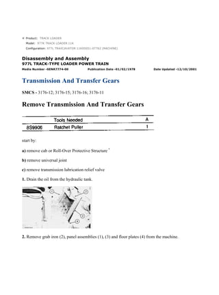
1. Product: TRACK LOADER
Model: 977K TRACK LOADER 11K
Configuration: 977L TRAXCAVATOR 11K05051-07762 (MACHINE)
Disassembly and Assembly
977L TRACK-TYPE LOADER POWER TRAIN
Media Number -SENR7774-00 Publication Date -01/02/1978 Date Updated -12/10/2001
Transmission And Transfer Gears
SMCS - 3176-12; 3176-15; 3176-16; 3176-11
Remove Transmission And Transfer Gears
start by:
a) remove cab or Roll-Over Protective Structure *
b) remove universal joint
c) remove transmission lubrication relief valve
1. Drain the oil from the hydraulic tank.
2. Remove grab iron (2), panel assemblies (1), (3) and floor plates (4) from the machine.
1/47
977L TRAXCAVATOR 11K05051-07762 (MACHINE)(UEG0732S - 00) - Document...
2021/11/7
https://127.0.0.1/sisweb/sisweb/techdoc/techdoc_print_page.jsp?returnurl=/sis...
2. 3. Disconnect the wiring harnesses at connection (6).
4. Remove the bolts that hold horn switch bracket (5) to the frame. Move bracket (5) to the side of
the machine.
5. Remove four screws (7) and move cover (8) from the instrument panel.
6. Remove the screws that hold instrument panel lights (11) in cover (8). Remove cover (8) from
the machine.
7. Remove the four bolts (9) and move instrument panel (10) to the top of the frame.
*
This operation is in the OPERATOR'S STATION DISASSEMBLY AND ASSEMBLY section.
2/47
977L TRAXCAVATOR 11K05051-07762 (MACHINE)(UEG0732S - 00) - Document...
2021/11/7
https://127.0.0.1/sisweb/sisweb/techdoc/techdoc_print_page.jsp?returnurl=/sis...
3. 8. Remove plate assembly (12) and the two angle assemblies that hold the plate assembly to the
frame.
9. Remove parking brake ratchet (16) and spring (15).
10. Remove springs (14) and (18). Remove rod assemblies (13) and (17) from the machine.
11. Remove rod assemblies (19) from the steering clutch hydraulic control and brake pedals.
3/47
977L TRAXCAVATOR 11K05051-07762 (MACHINE)(UEG0732S - 00) - Document...
2021/11/7
https://127.0.0.1/sisweb/sisweb/techdoc/techdoc_print_page.jsp?returnurl=/sis...
4. 12. Remove tube assembly (20) from the machine.
13. Disconnect tube assembly (21) from tube assembly (23).
14. Remove tube assemblies (22) from the machine.
15. Remove pedal and support assembly (24).
VIEW FROM UNDER MACHINE
16. Remove tube assemblies (25) and (26) from between the transmission and torque converter.
VIEW FROM UNDER MACHINE
17. Remove hose assemblies (27) and (28) from the machine.
4/47
977L TRAXCAVATOR 11K05051-07762 (MACHINE)(UEG0732S - 00) - Document...
2021/11/7
https://127.0.0.1/sisweb/sisweb/techdoc/techdoc_print_page.jsp?returnurl=/sis...
5. 18. Disconnect hose assembly (29) from the hydraulic pump.
19. Remove tube assemblies (32) and (33) as a unit.
20. Remove the bolts that hold heater hose clips (30) and (34) in position.
21. Remove transmission oil filter housing (31) from the torque converter housing.
22. Loosen the hose clamp next to the right side of the transmission and remove tube assembly
(35) from the hose and hydraulic pump.
23. Fasten a hoist to hydraulic pump (36). Remove the bolts and remove pump (36) from the
torque converter housing. The weight of the pump is 75 lb. (34 kg).
24. Remove magnetic screen group (38) from the machine.
5/47
977L TRAXCAVATOR 11K05051-07762 (MACHINE)(UEG0732S - 00) - Document...
2021/11/7
https://127.0.0.1/sisweb/sisweb/techdoc/techdoc_print_page.jsp?returnurl=/sis...
6. 25. Disconnect rod assemblies (39) from the transmission. Remove the bolts that hold bracket (37)
in position and move the transmission control linkage to the side of the machine.
26. Remove the bolt that holds the tube assembly for magnetic screen group (38) from the left
front of the transmission.
27. Disconnect hose assembly (40) from the back of the transmission.
28. Install three 5/8"-11 NC forged eyebolts in the top of the transmission. Fasten a hoist and tool
(A) to the transmission.
29. Remove the nuts and lockwashers that hold the transmission and transfer gears to the bevel
gear case.
30. Use two 1/2"-13 NC forcing screws to make a separation of the transmission and transfer gears
from the bevel gear case.
31. Use tool (A) to make the transmission and transfer gears level and remove the unit from the
top of the machine. The weight of the unit is 1050 lb. (473 kg).
Install Transmission And Transfer Gears
6/47
977L TRAXCAVATOR 11K05051-07762 (MACHINE)(UEG0732S - 00) - Document...
2021/11/7
https://127.0.0.1/sisweb/sisweb/techdoc/techdoc_print_page.jsp?returnurl=/sis...
7. 1. Fasten a hoist and tool (A) to the transmission and transfer gear case with three 5/8"-11 NC
forged eyebolts.
2. Make sure the O-ring seal is in position in the transfer gear case assembly and put clean oil in it.
3. Put the transmission and transfer gears in position in the bevel gear case. Make sure the pinion
gear engages correctly with the bevel gear.
VIEW FROM UNDER MACHINE
4. Install all of nuts (1) and the lockwashers that hold the transfer gear case assembly to the bevel
gear case.
5. Connect hose assembly (2) to the transmission.
7/47
977L TRAXCAVATOR 11K05051-07762 (MACHINE)(UEG0732S - 00) - Document...
2021/11/7
https://127.0.0.1/sisweb/sisweb/techdoc/techdoc_print_page.jsp?returnurl=/sis...
8. 6. Put bracket (3) and rod assemblies (4) in position. Install the bolts and lockwashers to hold
bracket (3). Connect rod assemblies (4) to the transmission.
7. Install the bolt that holds the tube assembly to the left front of the transmission.
8. Install magnetic screen group (5) and tighten the clamps on hose (6).
9. Install the O-ring seal on hydraulic pump (7) and put clean oil on it. Fasten a hoist to pump (7)
and put it in position in the torque converter housing. Install the bolts and lockwashers to hold the
pump in position.
10. Install the O-ring seal in tube assembly (8) and put clean oil on it. Connect tube assembly (8)
to the hydraulic pump and short hose at the right side of the transmission.
8/47
977L TRAXCAVATOR 11K05051-07762 (MACHINE)(UEG0732S - 00) - Document...
2021/11/7
https://127.0.0.1/sisweb/sisweb/techdoc/techdoc_print_page.jsp?returnurl=/sis...
9. 11. Put clean oil on the O-ring seals for transmission oil filter housing (9). Install the O-ring seals
and filter housing (9) on the torque converter housing.
12. Put clean oil on the O-ring seals for tube assemblies (10) and (12). Install the O-ring seals,
tube assembly (10), hose (11) and tube assembly (12).
13. Fasten the clips to the torque converter housing and transmission to hold heater hoses (13) in
position.
14. Put clean oil on the O-ring seal and install it in hose assembly (14). Connect hose assembly
(14) to the hydraulic pump.
VIEW FROM UNDER MACHINE
15. Put clean oil on the O-ring seals and install hose assemblies (15) and (16).
9/47
977L TRAXCAVATOR 11K05051-07762 (MACHINE)(UEG0732S - 00) - Document...
2021/11/7
https://127.0.0.1/sisweb/sisweb/techdoc/techdoc_print_page.jsp?returnurl=/sis...
10. VIEW FROM UNDER MACHINE
16. Put clean oil on the O-ring seals and install tube assemblies (17) and (18) on the machine.
17. Install pedal and support assembly (19).
18. Put clean oil on the O-ring seals and install tube assemblies (20) and (22). Connect tube
assembly (21) to tube assembly (23).
19. Connect rod assemblies (24) and (25) to the foot pedals and steering hydraulic control valve.
10/47
977L TRAXCAVATOR 11K05051-07762 (MACHINE)(UEG0732S - 00) - Docum...
2021/11/7
https://127.0.0.1/sisweb/sisweb/techdoc/techdoc_print_page.jsp?returnurl=/sis...
11. 20. Install the two springs (26) to the foot pedals.
21. Connect rod assemblies (27) to the foot pedals and brake actuating mechanisms.
22. Install spring (29) and ratchet (28) for the parking brake.
23. Install plate assembly (30) and the two angle assemblies that hold plate assembly (30) to the
machine.
24. Put the wiring harness and instrument panel (32) in position. Install the four bolts and
lockwashers to hold instrument panel (32).
25. Install the instrument panel lights in cover (31) and install the cover.
11/47
977L TRAXCAVATOR 11K05051-07762 (MACHINE)(UEG0732S - 00) - Docum...
2021/11/7
https://127.0.0.1/sisweb/sisweb/techdoc/techdoc_print_page.jsp?returnurl=/sis...
12. 26. Install the bolts to hold horn switch and bracket (33) in position.
27. Connect wiring harnesses (34) together.
28. Install floor plates (37), grab iron (35) and panel assemblies (36) on each side of the machine.
29. Fill the hydraulic system with oil to the correct level. See LUBRICATION AND
MAINTENANCE GUIDE.
end by:
a) install transmission lubrication relief valve
b) install universal joint
c) install cab or Roll-Over Protective Structure *
*
This operation is in the OPERATOR'S STATION DISASSEMBLY AND ASSEMBLY section.
Disassemble Transmission And Transfer Gears
12/47
977L TRAXCAVATOR 11K05051-07762 (MACHINE)(UEG0732S - 00) - Docum...
2021/11/7
https://127.0.0.1/sisweb/sisweb/techdoc/techdoc_print_page.jsp?returnurl=/sis...
13. start by:
a) remove transmission and transfer gears
1. Put the transmission and transfer gears in a horizontal position on the floor and use tool (A) and
blocks for support.
2. Remove cover (1) and the gasket from the transmission case.
13/47
977L TRAXCAVATOR 11K05051-07762 (MACHINE)(UEG0732S - 00) - Docum...
2021/11/7
https://127.0.0.1/sisweb/sisweb/techdoc/techdoc_print_page.jsp?returnurl=/sis...
14. 3. Remove the three bolts and washers that hold pressure control valve (2) in position and remove
the valve from the transmission case.
4. Remove all of O-ring seals (3) and (4) from the selector valve.
5. Remove sleeve (5) from the transmission case. Remove the O-ring seals from sleeve (5).
6. Remove the three bolts and washers that hold selector valve (6) in position and remove the
valve from the transmission case.
7. Remove O-ring seals (8) and sleeves (7) from the transmission. Remove the O-ring seals from
the sleeves.
NOTE: See DISASSEMBLE TRANSMISSION HYDRAULIC CONTROL VALVES to
disassemble the pressure and selector control valves.
14/47
977L TRAXCAVATOR 11K05051-07762 (MACHINE)(UEG0732S - 00) - Docum...
2021/11/7
https://127.0.0.1/sisweb/sisweb/techdoc/techdoc_print_page.jsp?returnurl=/sis...
15. 8. Fasten a hoist to the transmission and transfer gears and put the unit in position on tool (B) as
shown. Install four 1/2"-13 NC bolts and nuts to hold the unit on tool (B).
9. Remove all of bolts (9) and (10) from the transmission case.
10. Install two 1/2"-13 NC forged eyebolts and fasten a hoist to transmission case (11). Remove
case (11) from the transfer gear case. The weight of case (11) is 140 lb. (63 kg).
11. Remove spring (15) from the detent assembly and dowel.
12. Remove the nuts, washers and bolts that hold cam (13) and lever (14) to shaft (12).
13. Pull shaft (12) from the transmission case to remove lever (14) and cam (13).
14. Remove nut (16), the lockwasher and bolt to remove the detent assembly from the
transmission case.
15. Remove seal (17) from the transmission case. Use tool group (C) to remove bearings (18) and
the plug from the transmission case.
15/47
977L TRAXCAVATOR 11K05051-07762 (MACHINE)(UEG0732S - 00) - Docum...
2021/11/7
https://127.0.0.1/sisweb/sisweb/techdoc/techdoc_print_page.jsp?returnurl=/sis...
16. 16. Remove spring (19) from the dowel and detent assembly (21).
17. Remove the nut, washer and bolt that hold cam (20) to the shaft. Remove the shaft from the
transmission case to remove cam (20).
18. Remove nut (23), the washer and bolt to remove detent assembly (21).
19. Remove seal (22) and the two bearings from the transmission case.
20. Remove bolts (25) and the locks that hold bearing cage (24).
21. Install two 3/8"-16 NC forged eyebolts in the bearing cage and fasten a hoist as shown.
Remove the bearing cage and input shaft as a unit. The weight of the unit is 55 lb. (25 kg).
16/47
977L TRAXCAVATOR 11K05051-07762 (MACHINE)(UEG0732S - 00) - Docum...
2021/11/7
https://127.0.0.1/sisweb/sisweb/techdoc/techdoc_print_page.jsp?returnurl=/sis...
17. 22. Remove O-ring seal (26) from cage (24).
23. Remove the bolt, washer and flange (27) from the input shaft.
24. Use tool (D) to remove seal (28) from cage (24).
25. Remove ring (29) and spacer (30) from input shaft (31).
26. Remove the bearing cage from input shaft (31).
27. Remove ring (32) that holds bearing (33) in the cage.
17/47
977L TRAXCAVATOR 11K05051-07762 (MACHINE)(UEG0732S - 00) - Docum...
2021/11/7
https://127.0.0.1/sisweb/sisweb/techdoc/techdoc_print_page.jsp?returnurl=/sis...
18. 28. Use tool group (C) to remove bearing (33) from cage (24). The bearing can only be removed
from the side of cage (24) that ring (32) was removed.
29. Remove seal rings (34) from cage (24).
30. Remove ring (35) that holds bearing race (36) and gears (37) on the shaft.
31. Remove the two gears and bearing race from input shaft (31) with tooling (E).
TYPICAL EXAMPLE
32. Use a soft faced hammer to remove bearing cage (38) from the input shaft.
18/47
977L TRAXCAVATOR 11K05051-07762 (MACHINE)(UEG0732S - 00) - Docum...
2021/11/7
https://127.0.0.1/sisweb/sisweb/techdoc/techdoc_print_page.jsp?returnurl=/sis...
19. 33. Remove ring (39) and bearing (40) from cage (38).
NOTE: Put identification on each of the clutch housings for correct installation and alignment at
assembly. If the clutch plates and disc assemblies are to be used again keep these parts together
and do not mix them.
34. Remove bolts (41) that hold the clutch housings together.
35. Install tooling (F) to hold No. 1 piston in No. 1 clutch housing (42).
36. Install two 1/2"-13 NC forged eyebolts in No. 1 clutch housing (42). Fasten a hoist and
remove the piston and housing as a unit. The weight of the unit is 55 lb. (25 kg).
37. Remove springs (43) from the No. 2 clutch housing.
19/47
977L TRAXCAVATOR 11K05051-07762 (MACHINE)(UEG0732S - 00) - Docum...
2021/11/7
https://127.0.0.1/sisweb/sisweb/techdoc/techdoc_print_page.jsp?returnurl=/sis...
20. 38. Remove piston (44) from clutch housing (42). Remove the seal rings from the piston and
housing.
39. Remove the three disc assemblies (45) and two plates (46).
40. Remove ring gear (47).
41. Install two 3/8"-16 NC forged eyebolts in No. 1 carrier (48) and fasten a hoist. Remove carrier
(48). The weight of the carrier is 65 lb. (29 kg).
42. Remove bolts (50), the locks and plates (51) to remove gear (49) from No. 1 carrier (48).
20/47
977L TRAXCAVATOR 11K05051-07762 (MACHINE)(UEG0732S - 00) - Docum...
2021/11/7
https://127.0.0.1/sisweb/sisweb/techdoc/techdoc_print_page.jsp?returnurl=/sis...
21. 43. Remove shafts (55), gears (53) and washers (52) from No. 1 carrier (48). There is a washer on
each side of the gears. Remove bearings (54) from the gears.
NOTICE
When shafts (55) and (57) are removed, balls (56) and (62) can fall out
of the shafts. Take care not to loose balls (56) and (62).
44. Remove shafts (57), gears (58), washers (60) and tubes (61) from No. 1 carrier (48). There is a
washer on each side of the gears. Remove bearings (59) from the gears.
45. Use tool group (C) to remove bearing (63) from No. 1 carrier (48).
21/47
977L TRAXCAVATOR 11K05051-07762 (MACHINE)(UEG0732S - 00) - Docum...
2021/11/7
https://127.0.0.1/sisweb/sisweb/techdoc/techdoc_print_page.jsp?returnurl=/sis...
22. 46. Remove plate (64) from the No. 2 clutch housing. If necessary, remove dowels (65) from plate
(64).
47. Remove gear (67), the three disc assemblies (66), the two plates (69) and pins (68) from the
No. 2 clutch housing.
48. Install two 1/2"-13 NC forged eyebolts in No. 2 clutch housing (71) and fasten a hoist.
Remove housing (71). The weight of the housing is 50 lb. (23 kg).
49. Remove piston (70) from No. 2 clutch housing (71). Remove the seal rings from the piston and
housing.
50. Remove springs (72) from the No. 3 clutch housing.
51. Remove two disc assemblies (73) and plate (74) from the No. 3 clutch housing.
22/47
977L TRAXCAVATOR 11K05051-07762 (MACHINE)(UEG0732S - 00) - Docum...
2021/11/7
https://127.0.0.1/sisweb/sisweb/techdoc/techdoc_print_page.jsp?returnurl=/sis...
23. 52. Remove bolts (77), the locks and plates (76) to remove gear (75) from the No. 3 clutch
housing.
53. Install two 1/2"-13 NC forged eyebolts in No. 3 clutch housing (78) and fasten a hoist.
Remove clutch housing (78). The weight of the clutch housing is 55 lb. (25 kg).
54. Remove springs (81) from the No. 4 and 5 clutch housing.
55. Remove piston (79) from clutch housing (78). Remove the seal rings from the piston and
housing.
56. If necessary, remove dowels (80) from No. 3 clutch housing (78).
57. Remove the two disc assemblies (82) and plate (83).
58. Remove gear (84) and pins (85) from the No. 4 and 5 clutch housing.
59. Install tooling (F) to hold the No. 4 and 5 clutch pistons in position.
23/47
977L TRAXCAVATOR 11K05051-07762 (MACHINE)(UEG0732S - 00) - Docum...
2021/11/7
https://127.0.0.1/sisweb/sisweb/techdoc/techdoc_print_page.jsp?returnurl=/sis...
24. 60. Install two 1/2"-13 NC forged eyebolts in the No. 4 and 5 clutch housing (86) and fasten a
hoist. Remove clutch housing (86) and the pistons as a unit. The weight of the unit is 75 lb. (34
kg).
61. Remove springs (87) from the plate.
62. Remove tooling (F) and the pistons from clutch housing (86). Remove the seal rings from the
pistons and clutch housing.
63. Remove the two disc assemblies (88) and plate (89) from the plate.
64. Remove gear (90) from the plate.
65. Remove the three bolts (91) and washers from inside No. 2 carrier (92). Remove the three
bolts (93) and locks from No. 2 carrier (92).
24/47
977L TRAXCAVATOR 11K05051-07762 (MACHINE)(UEG0732S - 00) - Docum...
2021/11/7
https://127.0.0.1/sisweb/sisweb/techdoc/techdoc_print_page.jsp?returnurl=/sis...
25. 66. Install two 3/8"-16 NC forged eyebolts in No. 2 carrier (92) and fasten a hoist. Remove the
No. 2 carrier. The weight of the carrier is 50 lb. (23 kg).
67. Remove shafts (97), gears (95), gears (94) and washers (96) from No. 2 carrier (92). There is a
washer on each side of the gears. Remove the bearings from the gears.
NOTICE
When shafts (97) and (99) are removed, balls (98) and (101) can fall out
of the shafts. Take care not to loose balls (98) and (101).
68. Remove shafts (99), gears (102) and washers (100) from No. 2 carrier (92). There is a washer
on each side of the gears. Remove bearings (103) from gears (102).
25/47
977L TRAXCAVATOR 11K05051-07762 (MACHINE)(UEG0732S - 00) - Docum...
2021/11/7
https://127.0.0.1/sisweb/sisweb/techdoc/techdoc_print_page.jsp?returnurl=/sis...
26. 69. Use two 1/2"-13 NC forcing screws to remove plate (104) from the output transfer gears.
70. If necessary, remove dowels (105) from plate (104).
71. Remove the output transfer gears from tool (A) and put them on blocks with the input shaft
down. The weight of the transfer gears is approximately 150 lb. (68 kg).
72. Remove bolts (106) and the locks to remove cage (107).
73. Remove the plug from cage (107) and use a 6-40 screw to remove dowel (109) from the cage.
74. Remove bearing (108) from cage (107) with tool group (C).
26/47
977L TRAXCAVATOR 11K05051-07762 (MACHINE)(UEG0732S - 00) - Docum...
2021/11/7
https://127.0.0.1/sisweb/sisweb/techdoc/techdoc_print_page.jsp?returnurl=/sis...
27. 75. Remove the ring that holds input shaft (114) to gear (110) and remove the shaft.
76. Remove bolts (112) and the locks that hold case (113) and cover (111) together.
77. Install three 3/8"-16 NC forcing screws and tighten them evenly to remove cover (111) from
case (113).
78. Remove plug (117) and use a 6-40 screw to remove the dowel that holds bearing race (115).
NOTE: Remove the plug and use a 6-40 screw to remove the dowel that holds bearing race (116),
if so equipped.
79. Remove bearing races (115) and (116) from cover (111).
80. Remove gear (119) and pinion (118) from case (113).
27/47
977L TRAXCAVATOR 11K05051-07762 (MACHINE)(UEG0732S - 00) - Docum...
2021/11/7
https://127.0.0.1/sisweb/sisweb/techdoc/techdoc_print_page.jsp?returnurl=/sis...
28. Thank you so much for reading.
Please click the “Buy Now!”
button below to download the
complete manual.
After you pay.
You can download the most
perfect and complete manual in
the world immediately.
Our support email:
ebooklibonline@outlook.com