1. Product: TRACK LOADER
Model: 977K TRACK LOADER 48J
Configuration: 977K TRAXCAVATOR 48J00001-00585 (MACHINE)
Disassembly and Assembly
3306 VEHICULAR ENGINE FOR 977L TRACK-TYPE LOADER
Media Number -SENR7773-00 Publication Date -01/03/1978 Date Updated -12/10/2001
Fuel Injection Pump Housing And Governor
SMCS - 1286-11; 1286-12
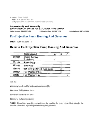
Remove Fuel Injection Pump Housing And Governor
start by:
a) remove hood, muffler and precleaner assembly
b) remove fuel injection lines
c) remove fuel filter and base
d) remove fuel priming pump
NOTE: The radiator guard is removed from the machine for better photo illustration for the
removal of the fuel injection pump housing and governor.
1/12
977K TRAXCAVATOR 48J00001-00585 (MACHINE)(UEH0138S - 00) - Document...
2021/10/18
https://127.0.0.1/sisweb/sisweb/techdoc/techdoc_print_page.jsp?returnurl=/sis...
2. 1. Disconnect rod assembly (2) from the lever on the governor.
2. Remove breather tube (3).
3. Remove drain hose (1) from the fuel system.
4. Remove plug (4). Tooling (A) can be used to turn the engine to put the No. 1 piston on top
center (TC) compression. If tooling (A) is used, remove the electric starting motor and install
tooling (A) in the flywheel housing. If tooling (A) is not used, the engine can be turned with the
bolt that holds the pulley for the vibration damper.
5. Put the No. 1 piston at top center (TC) compression as follows:
a) Turn the crankshaft clockwise (as seen from the front of the engine) until a 3/8"-16 NC bolt can
be installed in the hole from which plug (4) was removed. The bolt must go through the hole in the
flywheel housing and into the threaded hole in the flywheel.
NOTE: Never turn the crankshaft counterclockwise to install the bolt in the flywheel.
b) Disconnect the breather group from the valve cover. The rocker arms for the No. 1 piston can
be seen through the breather hole.
c) Check to see if both rocker arms can be moved backward and forward by hand through the
breather hole.
d) If both rocker arms can not be moved, the No. 1 piston is not at the top center (TC)
compression position. Remove the bolt from the flywheel. Turn the engine clockwise as seen from
the front of the engine one full turn 360° and install the bolt again.
2/12
977K TRAXCAVATOR 48J00001-00585 (MACHINE)(UEH0138S - 00) - Document...
2021/10/18
https://127.0.0.1/sisweb/sisweb/techdoc/techdoc_print_page.jsp?returnurl=/sis...
3. 6. Remove timing pin (5) from location (6).
7. Install timing pin (5) in the groove (slot) in the fuel injection pump camshaft.
8. Remove nuts (7) and cover (8) from the timing gear cover. Remove vee belts.
9. Remove bolt (9) and the washer and install tooling (C) on the end of bolt (9). Install and tighten
the bolt, washer and tooling (C) to hold the sleeve on the end of the fuel injection pump camshaft.
10. Install tooling (B) on the drive gear as shown. Tighten the center bolt of tooling (B) until the
drive gear is loose. Remove tooling (B), bolt (9) and the washers. The drive gear will stay in the
timing gear cover.
3/12
977K TRAXCAVATOR 48J00001-00585 (MACHINE)(UEH0138S - 00) - Document...
2021/10/18
https://127.0.0.1/sisweb/sisweb/techdoc/techdoc_print_page.jsp?returnurl=/sis...
4. 11. Fasten a hoist to the fuel injection pump housing and governor (10). Remove bracket (11).
Remove three nuts (12) and remove the fuel injection pump housing and governor. The weight of
the fuel injection pump housing and governor is 50 lb. (23 kg). Check the condition of the O-ring
seal in the body assembly of the fuel transfer pump. If the seal has damage, use a new part for
replacement.
Install Fuel Injection Pump Housing And Governor
1. Make sure the No. 1 piston is in the top center (TC) compression position. Make sure the timing
pin for the fuel system is in the groove (slot) in the fuel injection pump camshaft.
2. Install a new O-ring seal (1) in the body assembly of the fuel transfer pump.
3. Fasten a hoist to fuel injection pump housing and governor (2) and put the unit in position on
the timing gear plate. Install the three nuts and washers that hold it. Install bracket (3).
4/12
977K TRAXCAVATOR 48J00001-00585 (MACHINE)(UEH0138S - 00) - Document...
2021/10/18
https://127.0.0.1/sisweb/sisweb/techdoc/techdoc_print_page.jsp?returnurl=/sis...
5. 4. Put the drive gear (4) in position on the fuel injection pump camshaft. Install the washer and
bolt that hold the gear.
5. Install tooling (A) in the holes of the fuel injection pump drive gear. Put a torque of
approximately 50 lb.ft. (70 N·m) on the pump drive gear in a clockwise direction as seen from the
front of the engine. With the clockwise torque on the pump drive gear, tighten the bolt to a torque
of 110 ± 5 lb.ft. (149 ± 7 N·m).
6. Install the gasket and cover (5). Tighten the nuts that hold cover (5) to a torque of 20 ± 5 lb.ft.
(25 ± 7 N·m).
7. Remove timing pin (6) from location (7) and install in its original location. Install the bolt that
was removed from location (7).
5/12
977K TRAXCAVATOR 48J00001-00585 (MACHINE)(UEH0138S - 00) - Document...
2021/10/18
https://127.0.0.1/sisweb/sisweb/techdoc/techdoc_print_page.jsp?returnurl=/sis...
6. 8. Remove bolt (8) from the flywheel and install the plug in the flywheel housing.
9. If an engine turning tool was used, install the electric starting motor (9).
10. Install drain hose (13).
11. Install breather tube (10) and vee belts (12).
12. Connect rod assembly (11) to the lever on the governor.
end by:
a) install fuel priming pump
b) install fuel filter and base
c) install fuel injection lines
d) install hood, muffler and precleaner assembly
Separation Of Governor From Fuel Injection Pump Housing
start by:
a) remove fuel injection pump housing and governor
b) remove adapter housing and levers
6/12
977K TRAXCAVATOR 48J00001-00585 (MACHINE)(UEH0138S - 00) - Document...
2021/10/18
https://127.0.0.1/sisweb/sisweb/techdoc/techdoc_print_page.jsp?returnurl=/sis...
7. 1. Put the fuel injection pump housing and governor in position on tool (A).
2. Remove the bolts that hold the governor housing to the fuel injection pump housing.
3. Remove governor housing (2) from the fuel injection pump housing.
4. Remove cover (1) from over the torque spring.
5. Remove spring (5), (wave) washer (4) and guide (3) from the governor housing.
6. Remove the nut and the bolt that hold torque spring (6) to the fuel injection pump housing.
Remove the torque spring.
7. Remove seat (7) from over fueling spring (8).
7/12
977K TRAXCAVATOR 48J00001-00585 (MACHINE)(UEH0138S - 00) - Document...
2021/10/18
https://127.0.0.1/sisweb/sisweb/techdoc/techdoc_print_page.jsp?returnurl=/sis...
8. 8. Push in on lever (10) and remove pin (9) from the fuel injection pump housing.
9. Remove the ring that holds lever (10) to the dowel and remove the lever.
10. Remove riser (follower) (13) from the shaft.
11. Pull up on shaft (11) and remove the shaft and lever (12) from the fuel injection pump
housing.
NOTE: Shaft (11) has an O-ring seal on it which can make it difficult to remove the shaft from
the fuel injection pump housing.
12. Remove cover (14) for the flyweights with tool (B).
13. Install the timing pin in the groove (slot) in the fuel injection pump camshaft to keep the
camshaft from turning.
8/12
977K TRAXCAVATOR 48J00001-00585 (MACHINE)(UEH0138S - 00) - Document...
2021/10/18
https://127.0.0.1/sisweb/sisweb/techdoc/techdoc_print_page.jsp?returnurl=/sis...
9. 14. Remove the bolts that hold flyweight assembly (15) to the camshaft and remove the flyweight
assembly from the fuel injection pump housing.
15. Remove the timing pin from the fuel injection pump housing.
Connection Of Governor To Fuel Injection Pump Housing
1. Put the fuel injection pump housing on tool (A).
2. Install timing pin (1) to hold the camshaft from turning.
3. Put flyweight assembly (2) in position on the camshaft.
NOTICE
Make sure the pin that holds the shaft in the flyweight assembly is in
position before the flyweight assembly is installed.
4. Install three new bolts that hold the flyweight assembly to the camshaft.
NOTE: The bolts for holding the flyweight assembly to the camshaft have a locking material on
the threads. The bolts must not be used more than one time.
9/12
977K TRAXCAVATOR 48J00001-00585 (MACHINE)(UEH0138S - 00) - Document...
2021/10/18
https://127.0.0.1/sisweb/sisweb/techdoc/techdoc_print_page.jsp?returnurl=/sis...
10. 5. Install cover (3) over the flyweight assembly with tool (B).
6. Grind a taper on the bottom edge of a 1/8" screwdriver (4). Install the screwdriver through the
bolt hole in the governor housing. The screwdriver must fit evenly against the flyweight assembly
cover. Make a mark (stake) in four places around the cover in line with the groove in the camshaft.
NOTICE
Never install a used flyweight cover.
7. Put lever (7) on the dowel. Install ring (6).
8. Install pin (5) in the fuel injection pump housing with the round edge down.
9. Put the riser (follower) (11) in position between the flyweights. Lift the flyweights up with a
piece of wire and push the riser (follower) forward.
10. Put lever (10) in position in the groove of the riser (follower) (11) and the ball end engaged in
the sleeve shaft lever (8). Install shaft (9) that holds the lever in position.
10/12
977K TRAXCAVATOR 48J00001-00585 (MACHINE)(UEH0138S - 00) - Docume...
2021/10/18
https://127.0.0.1/sisweb/sisweb/techdoc/techdoc_print_page.jsp?returnurl=/sis...
11. NOTICE
If lever (10) is not installed correctly, the governor can not operate and
can cause the engine to over speed.
11. Install over fueling spring (12). Install the bolt and the nut that hold the torque spring in
position.
13. Install guide (18), (wave) washer (16) and spring (17) in the governor housing.
14. Put a new gasket (15) on the governor housing.
15. Install cover (19) over the torque spring. Install the two bolts that hold the cover in position.
16. Put the governor housing on the fuel injection pump housing. Install the bolts that hold the
governor housing in position.
end by:
a) install adapter housing and levers
b) install fuel injection pump housing and governor
11/12
977K TRAXCAVATOR 48J00001-00585 (MACHINE)(UEH0138S - 00) - Docume...
2021/10/18
https://127.0.0.1/sisweb/sisweb/techdoc/techdoc_print_page.jsp?returnurl=/sis...
12. Product: TRACK LOADER
Model: 977K TRACK LOADER 48J
Configuration: 977K TRAXCAVATOR 48J00001-00585 (MACHINE)
Disassembly and Assembly
3306 VEHICULAR ENGINE FOR 977L TRACK-TYPE LOADER
Media Number -SENR7773-00 Publication Date -01/03/1978 Date Updated -12/10/2001
Fuel Injection Pump Housing
SMCS - 1253-15; 1253-16
Disassemble Fuel Injection Pump Housing
start by:
a) separation of governor from fuel injection pump housing
b) remove fuel transfer pump
c) remove fuel injection pumps
1. Remove dowel (1) from the housing.
1/3
977K TRAXCAVATOR 48J00001-00585 (MACHINE)(UEH0138S - 00) - Document...
2021/10/18
https://127.0.0.1/sisweb/sisweb/techdoc/techdoc_print_page.jsp?returnurl=/sis...
13. 2. Loosen the screws that hold levers (3) to sleeve control shaft (2).
3. Remove sleeve control shaft (2) from the housing.
4. Remove lifter and roller assemblies (4).
NOTE: Put identification numbers on the lifter and roller assemblies. Identification numbers are
necessary for correct installation of the lifters and rollers.
5. Remove the camshaft from the housing.
Assemble Fuel Injection Pump Housing
1. Install camshaft (1) in the housing.
2/3
977K TRAXCAVATOR 48J00001-00585 (MACHINE)(UEH0138S - 00) - Document...
2021/10/18
https://127.0.0.1/sisweb/sisweb/techdoc/techdoc_print_page.jsp?returnurl=/sis...
14. 2. Install lifters and roller assemblies (5) in their respective bores.
NOTE: Install the lifters with the grooves of the lifters in alignment with pins (6).
3. Put sleeve control shaft (3) in the housing. Slide levers (2) on the shaft. Push the shaft in the
correct position.
4. Install dowel (4) in the housing.
end by:
a) install fuel transfer pump
b) connection of governor to fuel injection pump housing
c) make adjustment to the sleeve control shaft (See Testing and Adjusting for correct procedure)
d) install fuel injection pumps
3/3
977K TRAXCAVATOR 48J00001-00585 (MACHINE)(UEH0138S - 00) - Document...
2021/10/18
https://127.0.0.1/sisweb/sisweb/techdoc/techdoc_print_page.jsp?returnurl=/sis...
15. Product: TRACK LOADER
Model: 977K TRACK LOADER 48J
Configuration: 977K TRAXCAVATOR 48J00001-00585 (MACHINE)
Disassembly and Assembly
3306 VEHICULAR ENGINE FOR 977L TRACK-TYPE LOADER
Media Number -SENR7773-00 Publication Date -01/03/1978 Date Updated -12/10/2001
Governor
SMCS - 1264-15; 1264-16
Disassemble Governor
start by:
a) separation of governor from fuel injection pump housing
1. Remove shaft (2). Remove pin (1) from shaft.
2. Remove pins (3) from the flyweights. Remove flyweights (4).
3. Remove ring, races (6) and bearing from the riser (follower) (5).
1/6
977K TRAXCAVATOR 48J00001-00585 (MACHINE)(UEH0138S - 00) - Document...
2021/10/18
https://127.0.0.1/sisweb/sisweb/techdoc/techdoc_print_page.jsp?returnurl=/sis...
16. 4. Remove cover (7) and spring (8) from governor housing.
NOTE: There is force on the cover from the spring.
5. Remove seal (9) from cover.
6. Remove cover (10) for the low and high idle adjustment.
7. Remove locknut and screw (13) for the high idle adjustment.
8. Remove bolt (15) and washers for the low idle adjustment.
9. Remove spring (16) and guide.
10. Remove pin (14) and plate (11).
11. Remove shaft (12) from the housing.
12. Remove pin (18) and two spacers (17) from shaft.
NOTE: Earlier fuel systems have a ball in place of spacers (17) and pin (18).
2/6
977K TRAXCAVATOR 48J00001-00585 (MACHINE)(UEH0138S - 00) - Document...
2021/10/18
https://127.0.0.1/sisweb/sisweb/techdoc/techdoc_print_page.jsp?returnurl=/sis...
17. 13. Remove shaft (19) from the governor housing.
14. Remove washer (20) and levers (21) and (22) from governor housing.
15. Remove cover (23) from governor housing.
16. Remove seal (25) and bearing.
17. Remove seals (24) and (26) from governor housing.
Assemble Governor
3/6
977K TRAXCAVATOR 48J00001-00585 (MACHINE)(UEH0138S - 00) - Document...
2021/10/18
https://127.0.0.1/sisweb/sisweb/techdoc/techdoc_print_page.jsp?returnurl=/sis...
18. 1. Install bearing and seal in the housing with tool (A). The lip of the seal must be toward the
bearing.
2. Install seal (1) in housing with tool (A). The lip of seal must be toward inside of housing.
3. Install seal (2) in housing with tooling (B). The lip of seal must be toward the inside of housing.
4. Install shaft (3) in the housing.
5. Install plates (4), spacers (8) and pin (7) on shaft.
6. Install shaft (5) in housing and through washer (9) and levers (6).
7. Install pin (11) in holes of the plates.
4/6
977K TRAXCAVATOR 48J00001-00585 (MACHINE)(UEH0138S - 00) - Document...
2021/10/18
https://127.0.0.1/sisweb/sisweb/techdoc/techdoc_print_page.jsp?returnurl=/sis...
19. 8. Install screw (10) and locknut for high idle adjustment.
9. Install spring (13) and guide.
10. Install bolts (12) and washer for low idle adjustment.
NOTICE
After the fuel injection pump housing and governor have been installed
on the engine, make an adjustment for the high and low idle. See
GOVERNOR ADJUSTMENT as shown in TESTING AND
ADJUSTING.
11. Push plate and pin (11) over toward the bolt (12) and tighten the bolt.
12. Install seal in cover with tooling (B). The lip of seal must be toward the inside.
13. Install spring (15) in the cover. Install cover (14) on housing.
NOTICE
5/6
977K TRAXCAVATOR 48J00001-00585 (MACHINE)(UEH0138S - 00) - Document...
2021/10/18
https://127.0.0.1/sisweb/sisweb/techdoc/techdoc_print_page.jsp?returnurl=/sis...
20. The spring (15) must be installed with the end of spring as shown.
14. Install cover (16) for the idle adjustment screws.
15. Install bearing (19) between the races (18) on riser (follower) (17). Install ring (20) that holds
the washers on the riser (follower).
16. Install pin in shaft (23).
17. Install flyweights (22) and pin (21).
18. Install shaft (23) in the flyweight assembly.
end by:
a) connection of governor to fuel injection pump housing.
6/6
977K TRAXCAVATOR 48J00001-00585 (MACHINE)(UEH0138S - 00) - Document...
2021/10/18
https://127.0.0.1/sisweb/sisweb/techdoc/techdoc_print_page.jsp?returnurl=/sis...
21. Product: TRACK LOADER
Model: 977K TRACK LOADER 48J
Configuration: 977K TRAXCAVATOR 48J00001-00585 (MACHINE)
Disassembly and Assembly
3306 VEHICULAR ENGINE FOR 977L TRACK-TYPE LOADER
Media Number -SENR7773-00 Publication Date -01/03/1978 Date Updated -12/10/2001
Fuel Transfer Pump
SMCS - 1256-11; 1256-12
Remove Fuel Transfer Pump
start by:
a) remove fuel injection pump housing and governor
1. Install the fuel injection pump housing on tool (A).
NOTE: The fuel filter does not have to be removed to remove the fuel transfer pump.
2. Install timing pin (1) to keep the injection pump camshaft from turning during disassembly and
assembly.
1/5
977K TRAXCAVATOR 48J00001-00585 (MACHINE)(UEH0138S - 00) - Document...
2021/10/18
https://127.0.0.1/sisweb/sisweb/techdoc/techdoc_print_page.jsp?returnurl=/sis...
22. 3. Install bolt (B) in the threads of sleeve (3). Tighten the bolt until the sleeve can be removed.
NOTICE
Do not hit on the bolt or sleeve. This will cause damage to the unit.
4. Remove four bolts (4) that hold the pump body to the housing.
5. Remove body (2) from the housing.
6. Remove idler gear (6) from the pump body.
7. Remove O-ring seal (5) and the two lip-type seals from the body.
8. Remove drive gear (8) from the shaft.
9. Remove key (7) from the shaft.
Install Fuel Transfer Pump
2/5
977K TRAXCAVATOR 48J00001-00585 (MACHINE)(UEH0138S - 00) - Document...
2021/10/18
https://127.0.0.1/sisweb/sisweb/techdoc/techdoc_print_page.jsp?returnurl=/sis...
23. 1. Install the inner seal in the body with tool (A). The lip of the seal must be toward the pump
gears.
2. Install the outer seal in the body with tool (B). The lip of the seal must be toward the outside.
NOTICE
Always be careful not to scratch or cause damage to the machined
surface of the pump body.
3. Install O-ring seal (2) and idler gear (1) on the body.
3/5
977K TRAXCAVATOR 48J00001-00585 (MACHINE)(UEH0138S - 00) - Document...
2021/10/18
https://127.0.0.1/sisweb/sisweb/techdoc/techdoc_print_page.jsp?returnurl=/sis...
24. Thank you so much for reading.
Please click the “Buy Now!”
button below to download the
complete manual.
After you pay.
You can download the most
perfect and complete manual in
the world immediately.
Our support email:
ebooklibonline@outlook.com