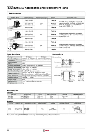
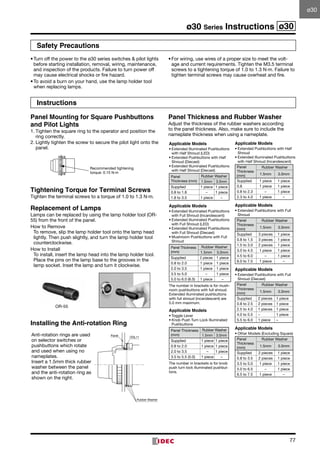
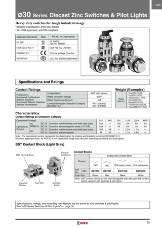
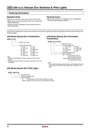
Downloaded 15 times


![43
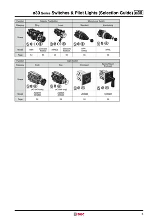
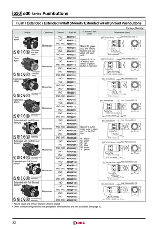
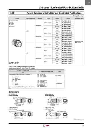
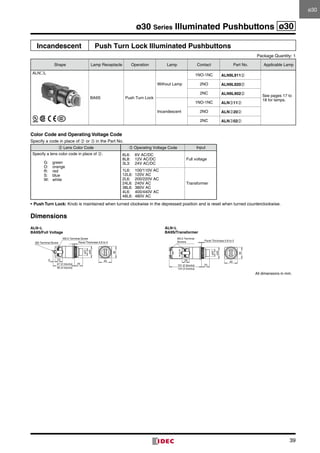
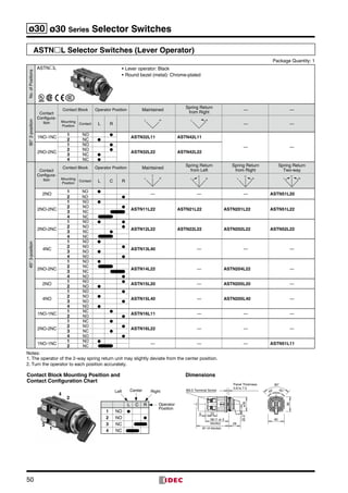
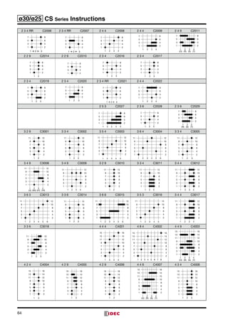
ø30 Series Selector Switches ø30
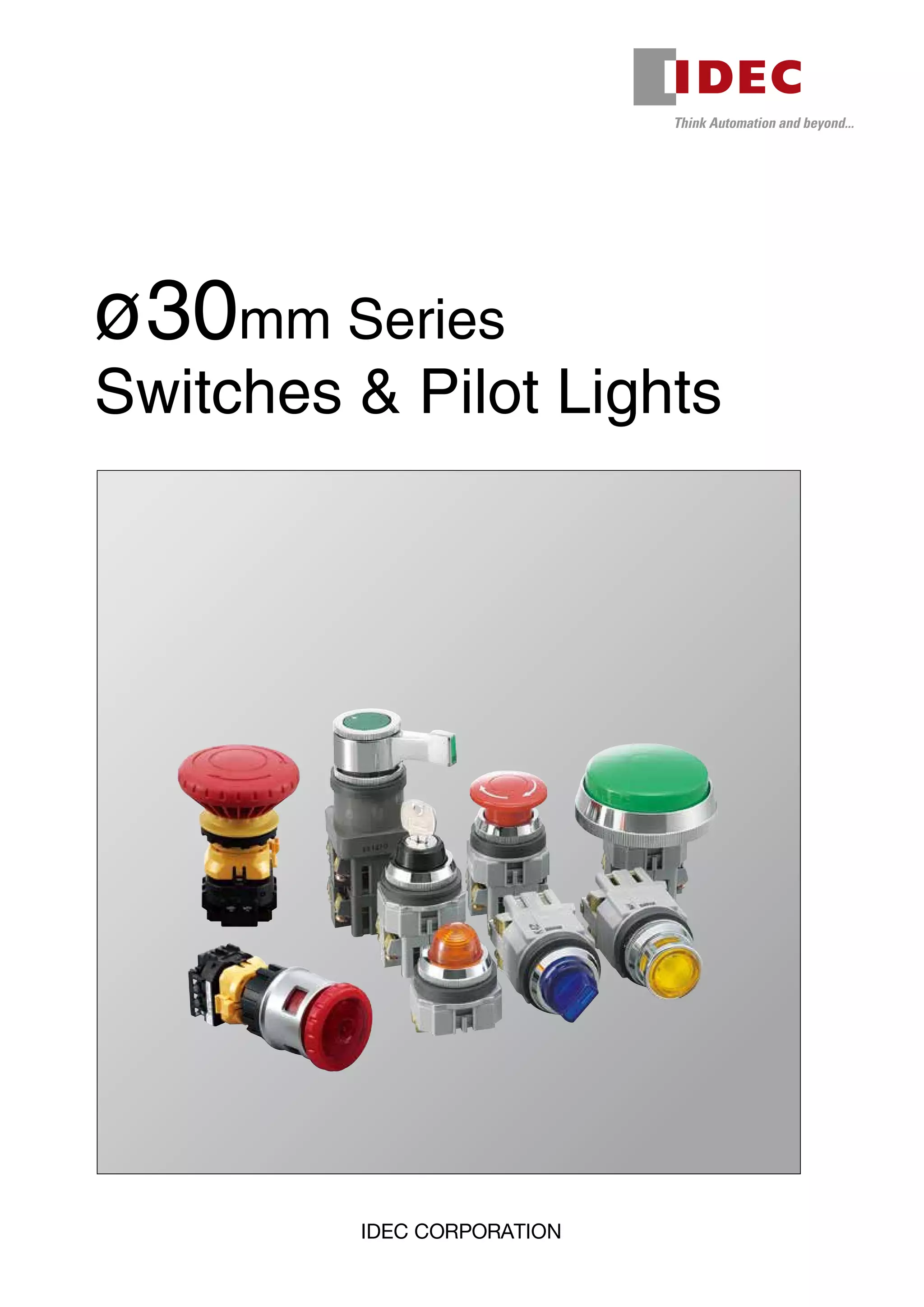
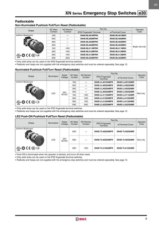
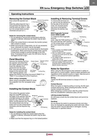
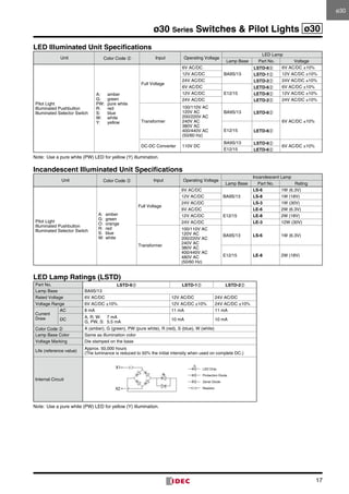
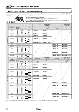
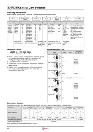
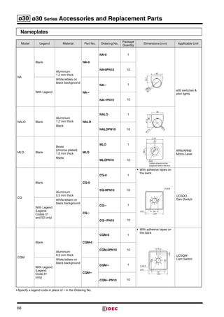
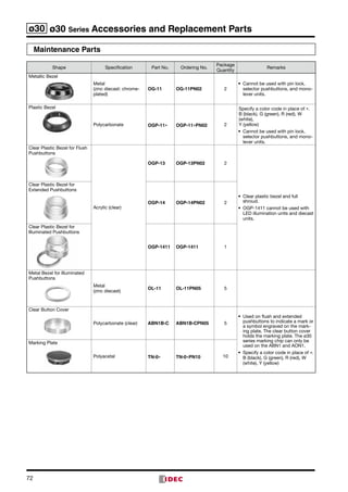
ASN-T Selector Switches (Knob Operator) [Twin Rod Type]
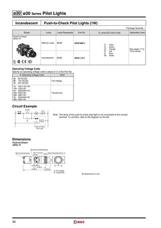
Package Quantity: 1
45°3-position
Contact
Configuration
Contact Block Operator Position Maintained
Spring Return
from Left
Maintained
Spring Return
from Right
Mounting
Position
Contact L C R
C
L R
C
L R
C
L R
C
L R
2NO
1 NO ●
ASN120-T ASN220-T2 NO ●
4NO
1 NO ●
ASN140-T ASN240-T
2 NO ●
3 NO ●
4 NO ●
2NO
1 NO ●
ASN2020-T2 NO ●
4NO
1 NO ●
ASN2040-T
2 NO ●
3 NO ●
4 NO ●
ASN-T are twin-rod units.
• Knob: Black
• Round bezel (metal): Chrome-plated
• When a terminal cover is required, order an applicable terminal cover referring to page 67.
• Nameplates are ordered separately.
ASN-T
1
3
2
4
ø30ø30](https://image.slidesharecdn.com/catalogue-n-bo-nt-nhn-30mm-idec-160426093822/85/Catalog-Den-bao-nut-nh-n-Phi-30-IDEC-Beeteco-com-43-320.jpg)
![45
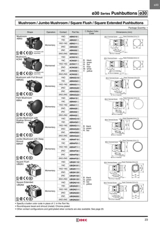
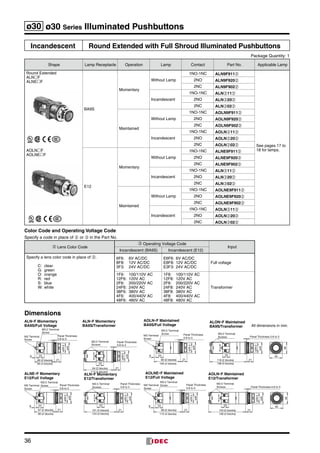
ø30 Series Selector Switches ø30
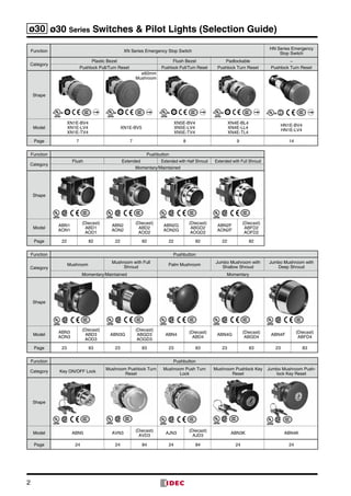
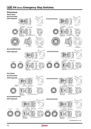
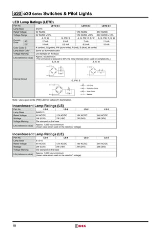
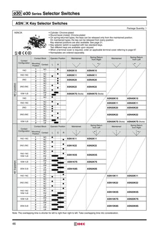
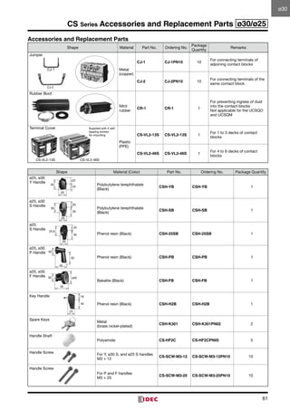
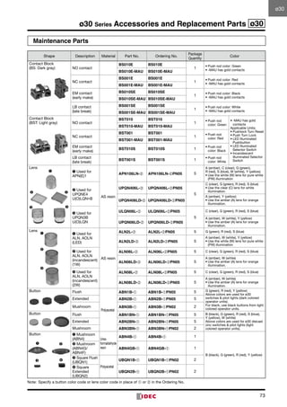
ASNL-T Selector Switches (Lever Operator) [Twin Rod Type]
Package Quantity: 1
45°3-position
Contact
Configuration
Contact Block Operator Position Maintained
Spring Return
from Left
Maintained
Spring Return
from Right
Mounting
Position
Contact L C R
C
L R
C
L R
C
L R
C
L R
2NO
1 NO ●
ASN1L20-T ASN2L20-T2 NO ●
4NO
1 NO ●
ASN1L40-T ASN2L40-T
2 NO ●
3 NO ●
4 NO ●
2NO
1 NO ●
ASN20L20-T2 NO ●
4NO
1 NO ●
ASN20L40-T
2 NO ●
3 NO ●
4 NO ●
ASN-T are twin-rod units.
• Lever: Black
• Round bezel (metal): Chrome-plated
• When a terminal cover is required, order an applicable terminal cover referring to page 67.
• Nameplates are ordered separately.
ASNL-T
1
24
3
ø30ø30](https://image.slidesharecdn.com/catalogue-n-bo-nt-nhn-30mm-idec-160426093822/85/Catalog-Den-bao-nut-nh-n-Phi-30-IDEC-Beeteco-com-45-320.jpg)
![47
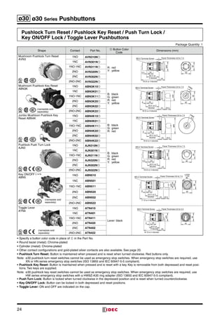
ø30 Series Selector Switches ø30
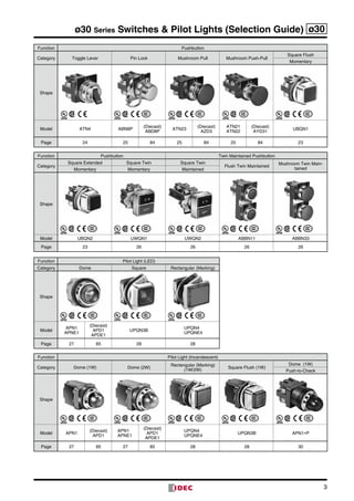
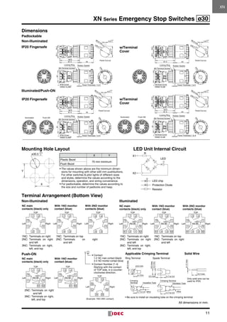
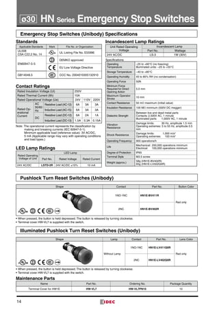
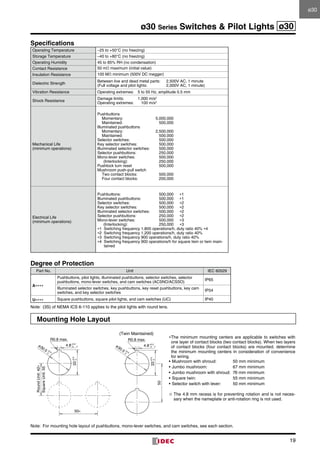
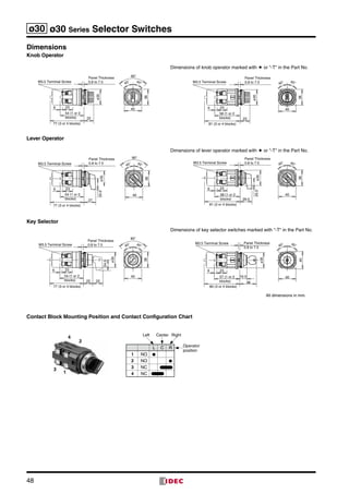
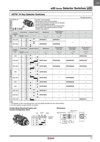
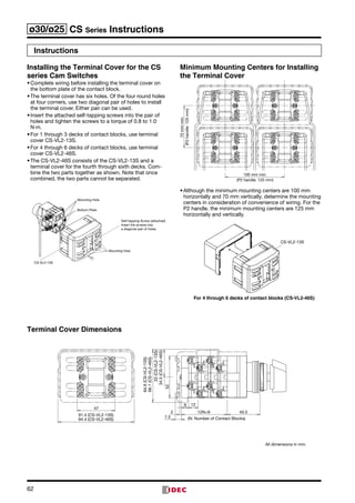
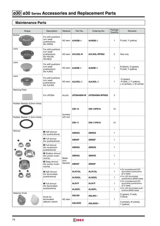
ASNK-T Key Selector Switches [Twin Rod Type]
Package Quantity: 1
90°2-position
Contact
Configuration
Contact Block Operator Position Maintained
Spring Return
from Right
Maintained
Spring Return
from Left
Mounting
Position
Contact L R
L R L R L R L R
1NO
1 NO ●
ASN3K10-T ASN4K10-T2 — —
1NO-1NC
1 NO ●
ASN3K11-T ASN4K11-T2 NC ●
2NO
1 NO ●
ASN3K20-T ASN4K20-T2 NO ●
2NO-2NC
1 NO ●
ASN3K22-T ASN4K22-T
2 NC ●
3 NO ●
4 NC ●
1EM-1LB
1 EM
ASN3K7S-T ASN4K7S-T2 LB
1NO
1 NO ●
ASN40K10-T2 — —
1NO-1NC
1 NO ●
ASN40K11-T2 NC ●
2NO
1 NO ●
ASN40K20-T2 NO ●
2NO-2NC
1 NO ●
ASN40K22-T
2 NC ●
3 NO ●
4 NC ●
1EM-1LB
1 EM
ASN40K7S-T2 LB
45°3-position
Contact
Configuration
Contact Block Operator Position Maintained
Spring Return
from Left
Maintained
Spring Return
from Right
Mounting
Position
Contact L C R
C
L R
C
L R
C
L R
C
L R
2NO
1 NO ●
ASN1K20-T ASN2K20-T2 NO ●
4NO
1 NO ●
ASN1K40-T ASN2K40-T
2 NO ●
3 NO ●
4 NO ●
2NO-2NC
1 NO ●
ASN1K5S-T ASN2K5S-T
2 NO ●
3 NC
4 NC
2NC
1 NC
ASN1K7S-T ASN2K7S-T2 NC
4NC
1 NC
ASN1K8S-T ASN2K8S-T
2 NC
3 NC
4 NC
2NO
1 NO ●
ASN20K20-T2 NO ●
4NO
1 NO ●
ASN20K40-T
2 NO ●
3 NO ●
4 NO ●
2NO-2NC
1 NO ●
ASN20K5S-T
2 NO ●
3 NC
4 NC
2NC
1 NC
ASN20K7S-T2 NC
4NC
1 NC
ASN20K8S-T
2 NC
3 NC
4 NC
ASN-T are twin-rod units.
• Cylinder: Chrome-plated
• Round bezel (metal): Chrome-plated
• On spring-returned types, the keys can be released only from the maintained position.
On maintained types, the key can be released from every position.
Key retained positions are also available. See page 21.
• Key selector switch is supplied with two standard keys.
Two different keys are available upon request.
• When a terminal cover is required, order an applicable terminal cover referring to page 67.
• Nameplates are ordered separately.
4
2
3
1
ASNK-T
ø30ø30](https://image.slidesharecdn.com/catalogue-n-bo-nt-nhn-30mm-idec-160426093822/85/Catalog-Den-bao-nut-nh-n-Phi-30-IDEC-Beeteco-com-47-320.jpg)
![52
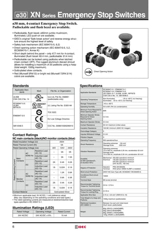
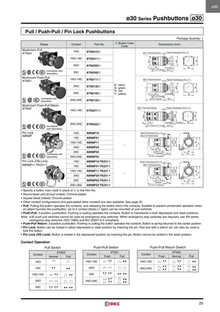
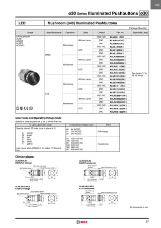
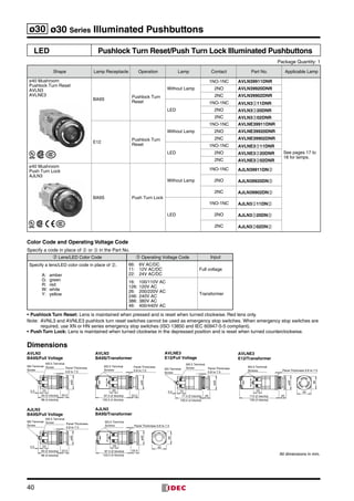
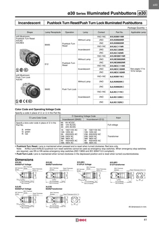
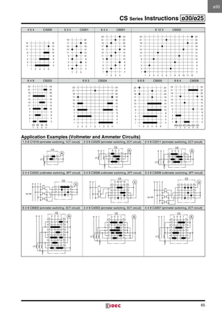
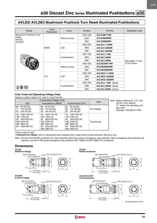
ø30 ø30 Series Illuminated Selector Switches
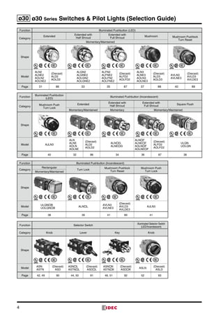
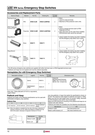
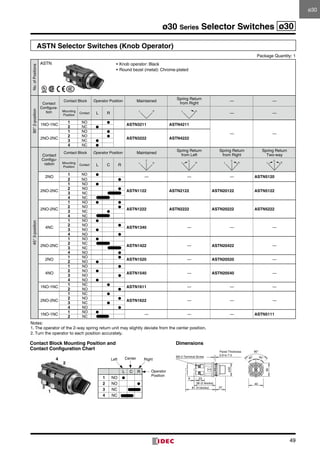
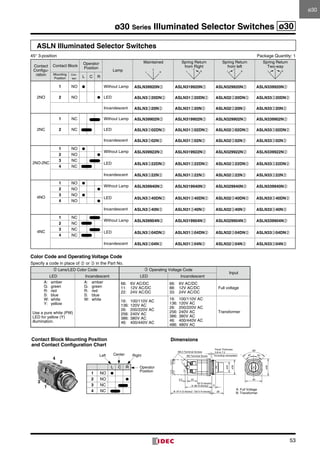
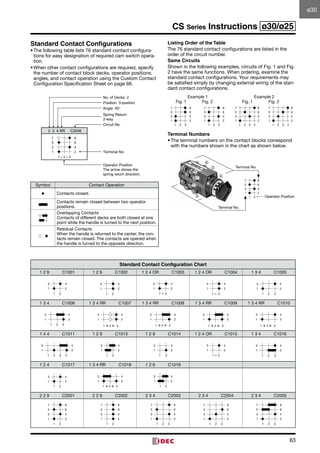
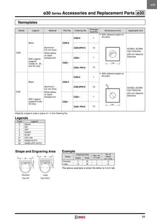
ASLN Illuminated Selector Switches
90° 2-position Package Quantity: 1
ASLN (Base BA9S)
Contact
Configu-
ration
Contact Block
Operator
Position
Lamp
Maintained
L R
Spring Return
from Right
L R
Spring Return
from Left
L R
Mounting
Position
Con-
tact
L R
1NO-1NC
1 NO ● Without Lamp ASLN29911N➁ ASLN219911N➁ ASLN229911N➁ ∗
2 NC ● LED ASLN2➂11DN➁ ASLN21➂11DN➁ ASLN22➂11DN➁ ∗
Incandescent ASLN2➂11N➁ ASLN21➂11N➁ ASLN22➂11N➁ ∗
2NO
1 NO ● Without Lamp ASLN29920N➁ ASLN219920N➁ ASLN229920N➁ ∗
2 NO ● LED ASLN2➂20DN➁ ASLN21➂20DN➁ ASLN22➂20DN➁ ∗
Incandescent ASLN2➂20N➁ ASLN21➂20N➁ ASLN22➂20N➁ ∗
2NO-2NC
1 NO ●
Without Lamp ASLN29922N➁ ASLN219922N➁ ASLN229922N➁ ∗
2 NC ●
3 NO ●
LED ASLN2➂22DN➁ ASLN21➂22DN➁ ASLN22➂22DN➁ ∗
4 NC ●
Incandescent ASLN2➂22N➁ ASLN21➂22N➁ ASLN22➂22N➁ ∗
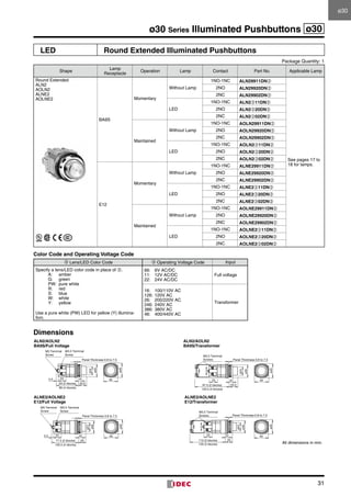
Color Code and Operating Voltage Code
Specify a code in place of ➁ or ➂ in the Part No.
➁ Lens/LED Color Code ➂ Operating Voltage Code
Input
LED Incandescent LED Incandescent
A: amber
G: green
R: red
S: blue
W: white
Y: yellow
Use a pure white (PW)
LED for yellow (Y)
illumination.
A: amber
G: green
R: red
S: blue
W: white
66: 6V AC/DC
11: 12V AC/DC
22: 24V AC/DC
66: 6V AC/DC
88: 12V AC/DC
33: 24V AC/DC
Full voltage
16: 100/110V AC
136: 120V AC
26: 200/220V AC
256: 240V AC
386: 380V AC
46: 400/440V AC
16: 100/110V AC
136: 120V AC
26: 200/220V AC
256: 240V AC
386: 380V AC
46: 400/440V AC
486: 480V AC
Transformer
On the 2-position selector switches marked with ∗ above, the contact operation is reversed as follows.
[Example]
1
2
3
4
L R
1 NO ●
2 NC ●
3 NO ●
4 NC ●
RightLeft
Operator
Position
40
ø40
235.5
28
9
ø35
ø25
M3.5 Terminal Screws
M3 Terminal Screw
63 (2 blocks)
A: 86 (4 blocks)
B: 97.5 (2 blocks), 120.5 (4 blocks)
Panel Thickness
0.8 to 7.5
(including nameplate)
90°
45° 45°
Contact Block Mounting Position
and Contact Configuration Chart
Dimensions
A: Full voltage
B: Transformer](https://image.slidesharecdn.com/catalogue-n-bo-nt-nhn-30mm-idec-160426093822/85/Catalog-Den-bao-nut-nh-n-Phi-30-IDEC-Beeteco-com-52-320.jpg)
![56
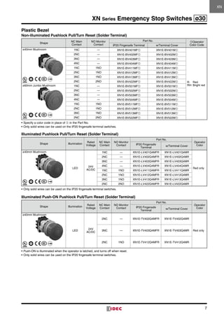
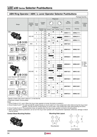
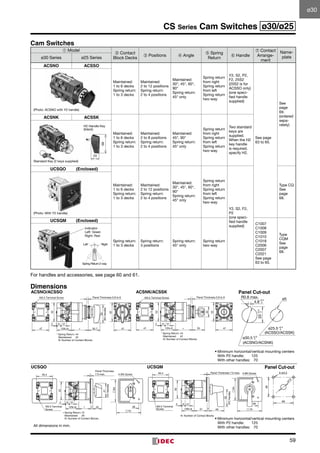
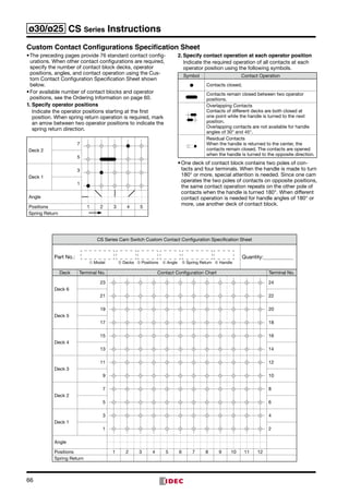
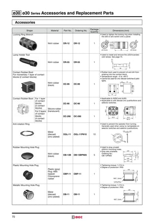
ø30 ARN/ARNS Series Mono-lever Switches
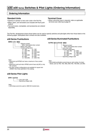
Mono-lever Switches
Operator Position Lever Action Part No. Dimensions (mm)
ARN (Long Lever)
2-position
(Up-Down)
Maintained ARN2-1010-➃B
Minimum horizontal/vertical mounting centers: 110
30
M3.5 Terminal
Screw
6 23
1 block: 47, 2 blocks: 70
3 blocks: 93, 4 blocks: 116
Panel Thickness 0.8 to 6
51
51
ø42
30
ø22
83
Spring return ARN2-2020-➃B
2-position
(Left-Right)
Maintained ARN2-0101-➃B
Spring return ARN2-0202-➃B
4-position
(Up-Down-Left-
Right)
Maintained ARN4-1111-➃B
Spring return ARN4-2222-➃B
ARNS (Short Lever)
2-position
(Up-Down)
Maintained ARNS2-1010-➃B
Minimum horizontal/vertical mounting centers: 70
30
6 23
63 51
51
ø42
30
M3.5 Terminal
Screw
Panel Thickness
0.8 to 6
ø22
1 block: 47, 2 blocks: 70
3 blocks: 93, 4 blocks: 116
Spring return ARNS2-2020-➃B
2-position
(Left-Right)
Maintained ARNS2-0101-➃B
Spring return ARNS2-0202-➃B
4-position
(Up-Down-Left-
Right)
Maintained ARNS4-1111-➃B
Spring return ARNS4-2222-➃B
ARNL (Interlocking)
The operator lever is locked only
in the center position.
2-position
(Up-Down)
Maintained ARNL2-1010-➃B
Minimum horizontal/vertical mounting centers: 110
30
6 23
51
51
ø42
30
ø22
83
M3.5 Terminal
Screw Panel Thickness 0.8 to 6
1 block: 47, 2 blocks: 70
3 blocks: 93, 4 blocks: 116
Spring return ARNL2-2020-➃B
2-position
(Left-Right)
Maintained ARNL2-0101-➃B
Spring return ARNL2-0202-➃B
4-position
(Up-Down-Left-
Right)
Maintained ARNL4-1111-➃B
Spring return ARNL4-2222-➃B
Specify Contact Configuration from the table below in place of ➃.
Terminal covers are ordered separately.
Ordering Information
When ordering, specify items ➀ to ➄ according to the following
example.
[Example]
ARN 4 – 1012 – 2 0 0 0 0 2 1 1 B
➀ ➁ ➂ ➃ ➄
LeftRightUp Down
➀
Model
➁ No. of
Contact
Blocks
➂ Lever Action
➃ Contact
Arrangement
➄ Lever
Knob
Color
ARN
ARNS
ARNL
1: 1 block
2: 2 blocks
3: 3 blocks
4: 4 blocks
Order of Entry:
UpRight
DownLeft
1: Maintained
2: Spring return
0: Blocked
Order of Entry:
UpRight
DownLeft
10: 1NO
01: 1NC
11: 1NO-1NC
20: 2NO
02: 2NC
00: Blocked
B: black
• To calculate the number of contact blocks required, add the number
of NO and NC contacts on each pair of adjoining positions (up +
right, right + down, down + left, and left + up). The largest of the four
sums is the number of contact blocks required. Up to four contact blocks can be mounted.
• When UL and CSA markings are required on the mono-lever switch, specify as shown below.
[Example] ARN4-1012-20000211B- U
R0.8 max.
0
+0.5
0
+0.2
+0.5
0
4.8
33
ø30.5
68
0
31
68
31 23
64
Panel Cut-Out Mono-Lever with Terminal CoverLever Operator Position
Right
Up
Left
Down
ContactBlockPosition
TerminalNo.
Direction of Lever Operation
TerminalNo.
Contact
Block
TypeLever Operation Mode
1: Maintained
2: Spring return
0: Blocked
1 0 1 2
1
1 NO – – – 2
BR-2E
3 – – NC – 4
2
5 – NO ∗ – – 6
BR-1E
7 – – – NO 8
3
9 NO – – – 10
BR-2E
11 – – NC – 12
4
13 – NC ∗ – – 14
BR-3E
15 – – – NC 16
∗: Contacts marked with ∗ do not operate.](https://image.slidesharecdn.com/catalogue-n-bo-nt-nhn-30mm-idec-160426093822/85/Catalog-Den-bao-nut-nh-n-Phi-30-IDEC-Beeteco-com-56-320.jpg)
![78
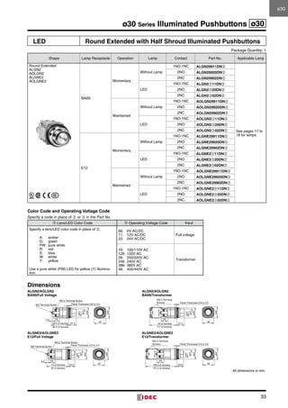
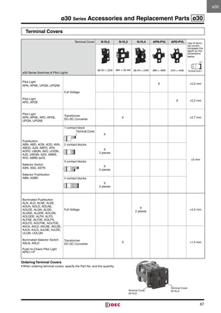
ø30 ø30 Series Instructions
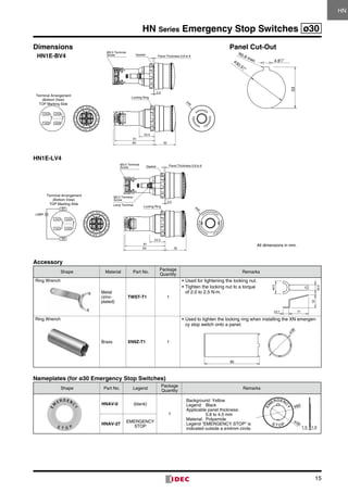
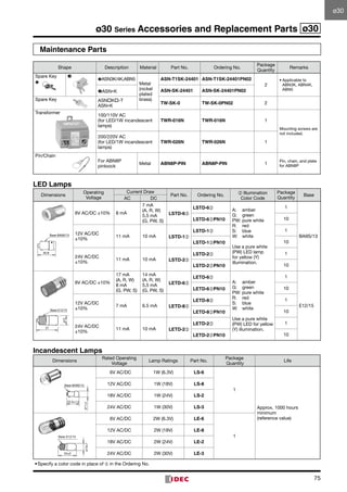
Installation of LED Illuminated Units
1. Note the polarity for wiring when connecting to DC-DC
converter unit.
Terminal No. Polarity
X1 Positive
X2 Negative
2. Transformer units are recommended for use in areas
subjected to noise.
3. Notes for Pure White LED Lamps
• Do not use the pure white LED outdoors, otherwise it will
lead to the degradation of brightness and color. Do not
remove or apply shock to the cap on the pure white LED
lamp, otherwise it may break or damage the cap.
• For the pure white LED, use a white lens. The illumination
color will be dull if a different color is used.
Notes on LED Illuminated Units
LED lamps consist of semiconductors. If the applied
voltage exceeds the rated voltage, LED elements may
deteriorate due to overheat, resulting in significant
decrease in luminance, hue change, or failure of lighting.
Also, if an extraneous noise, transient voltage, or transient
current is applied to the circuit, similar effects may occur.
When using LED lamps, observe the following instructions.
Rated Voltage
The LED lamps are rated at 6V, 12V, or 24V AC/DC, and
can be used within ±10% the rated voltage of either AC or
DC.
DC Power
1. Switching power supply
Regulated voltage from switching power supply is best
suited. Make sure to use within the rated voltage of the
LED lamp.
2. Rechargeable battery
Note that the battery voltage may exceed the rated volt
age of the LED lamp while the battery is being charged
and immediately after the charging is complete. Be sure
to use the LED lamp on a voltage of ±10% the rated
voltage.
3. Full-wave rectification
Since the LED lamp is AC/DC compatible, a diode
bridge for rectification is not necessary. If the LED lamp
is used on a full-wave rectification current through a
diode bridge, the rectifier diodes will reduce the voltage,
resulting in lower luminance.
4. Single-phase half-wave rectification
This is not suitable for the power source of LED lamps.
Use constant-voltage DC power.
Noise
LED elements deteriorate due to extraneous noise, result
ing in significant decrease in luminance, hue change, or
failure of lighting. When such effects are anticipated, take a
protection measure shown below, such as RC elements or
a surge absorber.
[Protection Example 1] For AC circuit
LED with
transformer LED
R
C
LEDRyRelay
coil or
solenoid
R
C
LED with
transformer
(Reference values) R: 120
C: 0.1 F
[Protection Example 2] For DC circuit
Ry LED DiodeRelay
coil or
solenoid
+
–
(Reference values of the diode)
Forward current: More than the Ry coil current
Reverse withstand voltage: Ry coil current ¥ 10
Countermeasures against Dim Lighting
1. Leakage currents through the transistors or a contact
protection circuit may cause the LED lamp to illuminate
dimly even when the output is off.
2. When the LED lamp is illuminated by a transistor output,
take the following measure.
[Circuit Example]
Connect shunt resistor R in parallel with the LED lamp.
R
Io
Io: Leakage current when the output is off
R: Shunt resistor
LED](https://image.slidesharecdn.com/catalogue-n-bo-nt-nhn-30mm-idec-160426093822/85/Catalog-Den-bao-nut-nh-n-Phi-30-IDEC-Beeteco-com-78-320.jpg)
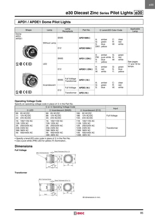
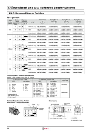
![90
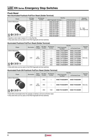
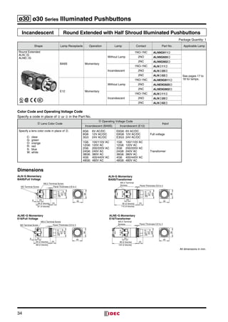
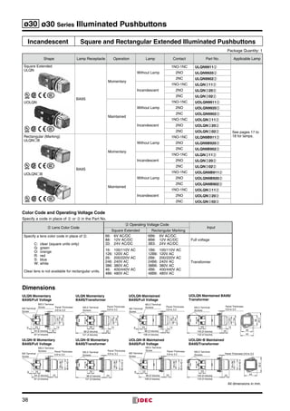
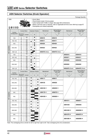
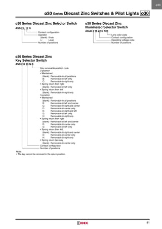
ø30 ø30 Diecast Zinc Series Selector Switches
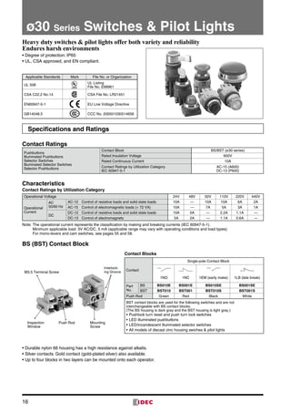
ASD Selector Switches (Knob Operator)
No.ofPositions
ASD
90°2-position
Contact
Configu-
ration
Contact Block Operator Position Maintained
Spring Return
from Right
Spring Return
from Left
Mounting
Position
Contact L R
L R L R L R
1NO
1 NO ●
ASD210N ASD2110N ASD2210N ∗
—
2 Dummy
1NO-1NC
1 NO ●
ASD211N ASD2111N ASD2211N ∗2 NC ●
2NO
1 NO ●
ASD220N ASD2120N ASD2220N ∗2 NO ●
2NO-2NC
1 NO ●
ASD222N ASD2122N ASD2222N ∗
2 NC ●
3 NO ●
4 NC ●
45°3-position
Contact
Configu-
ration
Contact Block Operator Position Maintained
Spring Return
from Right
Spring Return
from Left
Spring Return
Two-way
Mounting
Position
Contact L C R
C
L R
C
L R
C
L R
C
L R
2NO
1 NO ●
ASD320N ASD3120N ASD3220N ASD3320N
2 NO ●
4NO
1 NO ●
ASD340N ASD3140N ASD3240N ASD3340N
2 NO ●
3 NO ●
4 NO ●
2NO-2NC
1 NO ●
ASD322N ASD3122N ASD3222N ASD3322N
2 NO ●
3 NC
4 NC
2NC
1 NC
ASD302N ASD3102N ASD3202N ASD3302N
2 NC
4NC
1 NC
ASD304N ASD3104N ASD3204N ASD3304N
2 NC
3 NC
4 NC
• Knob: Black
• Round bezel (metal): Chrome-plated
• Selector switches with one contact block contain a dummy block.
• On the 2-position selector switches marked with ∗ above, the contact operation is reversed as follows.
[Example]
L C R
1 NO ●
2 NO ●
3 NC
4 NC
Center RightLeft
Operator
Position
Contact Block Mounting Position and
Contact Configuration Chart
Dimensions
24
1
3
M3.5 Terminal Screw
40
5.5 23
ø35
53 (1 or 2
blocks)
76 (4 blocks)
21
ø40
90°
45° 45°
Panel Thickness 0.8 to 7.5
All dimensions in mm.](https://image.slidesharecdn.com/catalogue-n-bo-nt-nhn-30mm-idec-160426093822/85/Catalog-Den-bao-nut-nh-n-Phi-30-IDEC-Beeteco-com-90-320.jpg)
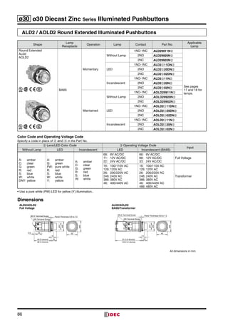
![91
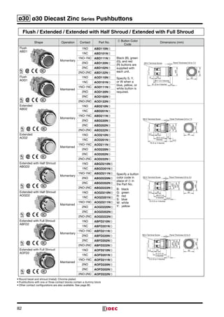
ø30 Diecast Zinc Series Selector Switches ø30
ASDL Selector Switches (Lever Operator)
No.ofPositions
ASDL
90°2-position
Contact
Configu-
ration
Contact Block Operator Position Maintained
Spring Return
from Right
Spring Return
from Left
Mounting
Position
Contact L R
L R L R L R
1NO
1 NO ●
ASD2L10N ASD21L10N ASD22L10N ∗
—
2 Dummy
1NO-1NC
1 NO ●
ASD2L11N ASD21L11N ASD22L11N ∗2 NC ●
2NO
1 NO ●
ASD2L20N ASD21L20N ASD22L20N ∗2 NO ●
2NO-2NC
1 NO ●
ASD2L22N ASD21L22N ASD22L22N ∗
2 NC ●
3 NO ●
4 NC ●
45°3-position
Contact
Configu-
ration
Contact Block Operator Position Maintained
Spring Return
from Right
Spring Return
from Left
Spring Return
Two-way
Mounting
Position
Contact L C R
C
L R
C
L R
C
L R
C
L R
2NO
1 NO ●
ASD3L20N ASD31L20N ASD32L20N ASD33L20N
2 NO ●
4NO
1 NO ●
ASD3L40N ASD31L40N ASD32L40N ASD33L40N
2 NO ●
3 NO ●
4 NO ●
2NO-2NC
1 NO ●
ASD3L22N ASD31L22N ASD32L22N ASD33L22N
2 NO ●
3 NC
4 NC
2NC
1 NC
ASD3L02N ASD31L02N ASD32L02N ASD33L02N
2 NC
4NC
1 NC
ASD3L04N ASD31L04N ASD32L04N ASD33L04N
2 NC
3 NC
4 NC
• Lever: Black
• Round bezel (metal): Chrome-plated
• Selector switches with one contact block contain a dummy block.
• On the 2-position selector switches marked with ∗ above, the contact operation is reversed as follows.
[Example]
M3.5 Terminal Screw
40
5.5 23
ø35
53 (1 or 2
blocks)
76 (4 blocks)
21.5
ø40
90°
45° 45°
Panel Thickness 0.8 to 7.5
L C R
1 NO ●
2 NO ●
3 NC
4 NC
Center RightLeft
Operator
Position
Contact Block Mounting Position and
Contact Configuration Chart
Dimensions
24
1
3
All dimensions in mm.
ø30](https://image.slidesharecdn.com/catalogue-n-bo-nt-nhn-30mm-idec-160426093822/85/Catalog-Den-bao-nut-nh-n-Phi-30-IDEC-Beeteco-com-91-320.jpg)
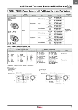
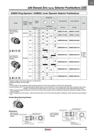
![92
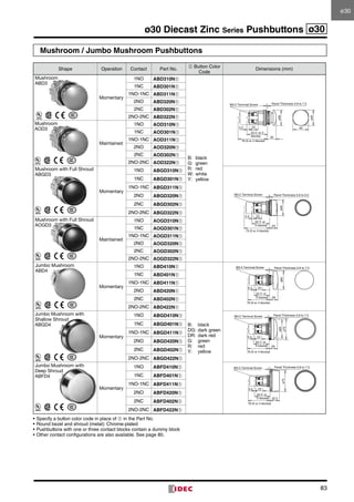
ø30 ø30 Diecast Zinc Series Selector Switches
ASDK Key Selector Switches
No.ofPositions
ASDK
90°2-position
Contact
Configu-
ration
Contact Block Operator Position Maintained
Spring Return
from Right
Spring Return
from Left
Mounting
Position
Contact L R
L R L R L R
1NO
1 NO ●
ASD2K10N ASD21K10N ASD22K10N ∗
—
2 Dummy
1NO-1NC
1 NO ●
ASD2K11N ASD21K11N ASD22K11N ∗2 NC ●
2NO
1 NO ●
ASD2K20N ASD21K20N ASD22K20N ∗2 NO ●
2NO-2NC
1 NO ●
ASD2K22N ASD21K22N ASD22K22N ∗
2 NC ●
3 NO ●
4 NC ●
45°3-position
Contact
Configu-
ration
Contact Block Operator Position Maintained
Spring Return
from Right
Spring Return
from Left
Spring Return
Two-way
Mounting
Position
Contact L C R
C
L R
C
L R
C
L R
C
L R
2NO
1 NO ●
ASD3K20N ASD31K20N ASD32K20N ASD33K20N
2 NO ●
4NO
1 NO ●
ASD3K40N ASD31K40N ASD32K40N ASD33K40N
2 NO ●
3 NO ●
4 NO ●
2NO-2NC
1 NO ●
ASD3K22N ASD31K22N ASD32K22N ASD33K22N
2 NO ●
3 NC
4 NC
2NC
1 NC
ASD3K02N ASD31K02N ASD32K02N ASD33K02N
2 NC
4NC
1 NC
ASD3K04N ASD31K04N ASD32K04N ASD33K04N
2 NC
3 NC
4 NC
• Cylinder: Black
• Round bezel (metal): Chrome-plated
• On the spring-returned, the keys can be released only from the maintained positions. On the maintained, the key can be released from
every position. Key retained positions are also available. See page 81.
• Key selector switches are supplied with two standard keys.
• Key selector switches with one contact block contain a dummy block.
• On the 2-position selector switches marked with ∗ above, the contact operation is reversed as follows.
[Example]
M3.5 Terminal Screw
40
5.5 23
ø35
53 (1 or 2
blocks)
76 (4 blocks)
ø40
9
16.5
38
90°
45° 45°
Panel Thickness 0.8 to 7.5
L C R
1 NO ●
2 NO ●
3 NC
4 NC
Center RightLeft
Operator
Position
Contact Block Mounting Position and
Contact Configuration Chart
Dimensions
2
4
1
3
All dimensions in mm.](https://image.slidesharecdn.com/catalogue-n-bo-nt-nhn-30mm-idec-160426093822/85/Catalog-Den-bao-nut-nh-n-Phi-30-IDEC-Beeteco-com-92-320.jpg)
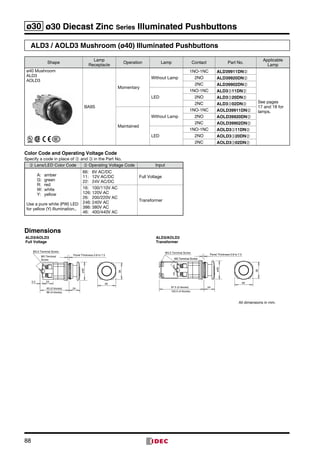
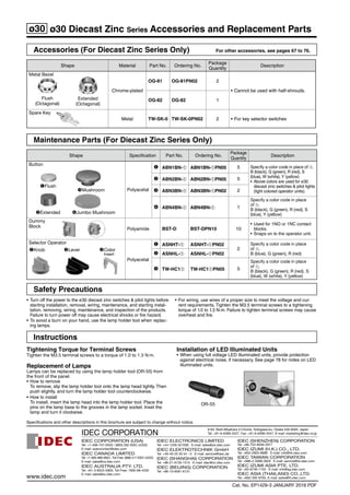
![93
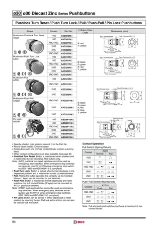
ø30 Diecast Zinc Series Illuminated Selector Switches ø30
ASLD Illuminated Selector Switches
90° 2-position
ASLD (Base BA9S)
Contact
Configu-
ration
Contact
Block
Operator
Position
Lamp
Maintained
L R
Spring Return
from Right
L R
Spring Return
from Left
L R
Mounting
Position
Contact L R
1NO-1NC
1 NO ● Without Lamp ASLD29911N➁ ASLD219911N➁ ASLD229911N➁ ∗
2 NC ● LED ASLD2➂11DN➁ ASLD21➂11DN➁ ASLD22➂11DN➁ ∗
Incandescent ASLD2➂11N➁ ASLD21➂11N➁ ASLD22➂11N➁ ∗
2NO
1 NO ● Without Lamp ASLD29920N➁ ASLD219920N➁ ASLD229920N➁ ∗
2 NO ● LED ASLD2➂20DN➁ ASLD21➂20DN➁ ASLD22➂20DN➁ ∗
Incandescent ASLD2➂20N➁ ASLD21➂20N➁ ASLD22➂20N➁ ∗
2NO-2NC
1 NO ●
Without Lamp ASLD29922N➁ ASLD219922N➁ ASLD229922N➁ ∗
2 NC ●
3 NO ●
LED ASLD2➂22DN➁ ASLD21➂22DN➁ ASLD22➂22DN➁ ∗
4 NC ●
Incandescent ASLD2➂22N➁ ASLD21➂22N➁ ASLD22➂22N➁ ∗
Color Code and Operating Voltage Code
Specify a code in place of ➁ or ➂ in the Part No.
➁ Lens/LED Color Code ➂ Operating Voltage Code
Input
LED Incandescent LED Incandescent
A: amber
G: green
R: red
S: blue
W: white
Y: yellow
Use a pure white
(PW) LED for yellow
(Y) illumination.
A: amber
G: green
R: red
S: blue
W: white
66: 6V AC/DC
11: 12V AC/DC
22: 24V AC/DC
66: 6V AC/DC
88: 12V AC/DC
33: 24V AC/DC
Full voltage
16: 100/110V AC
136: 120V AC
26: 200/220V AC
256: 240V AC
386: 380V AC
46: 400/440V AC
16: 100/110V AC
136: 120V AC
26: 200/220V AC
256: 240V AC
386: 380V AC
46: 400/440V AC
486: 480V AC
Transformer
• On the 2-position selector switches marked with ∗ above, the contact operation is reversed as follows.
[Example]
1
2
3
4
40
ø40
235.5
28
9
ø35
ø25
M3.5 Terminal Screws
M3 Terminal Screw
63 (2 blocks)
A: 86 (4 blocks)
B: 97.5 (2 blocks), 120.5 (4 blocks)
Panel Thickness
0.8 to 7.5
(including nameplate)
90°
45° 45°
Contact Block Mounting Position
and Contact Configuration Chart
Dimensions
All dimensions in mm.
L R
1 NO ●
2 NC ●
3 NO ●
4 NC ●
RightLeft
Operator
Position
A: Full voltage
B: Transformer
ø30](https://image.slidesharecdn.com/catalogue-n-bo-nt-nhn-30mm-idec-160426093822/85/Catalog-Den-bao-nut-nh-n-Phi-30-IDEC-Beeteco-com-93-320.jpg)

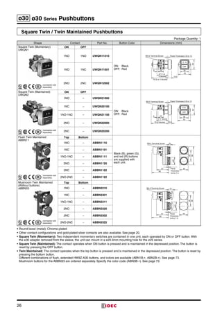
The document provides information on IDEC's ø30mm series switches and pilot lights, including: - Emergency stop switches and illuminated pushbuttons in various configurations with up to 4 NC contacts. Models have plastic bezels, are pushlock with pull/turn reset, and have IP20 fingersafe terminals. - Technical specifications for the switches like applicable standards, contact ratings, operating conditions, and certifications. - Part numbers, configurations, and other details for non-illuminated and illuminated emergency stop switch models.


