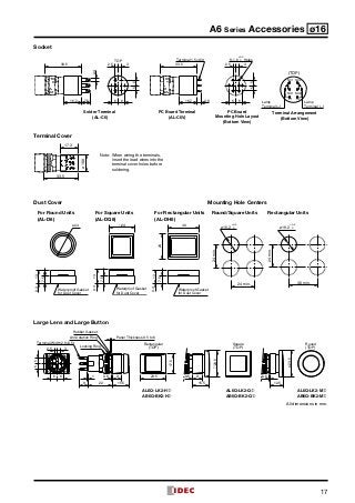
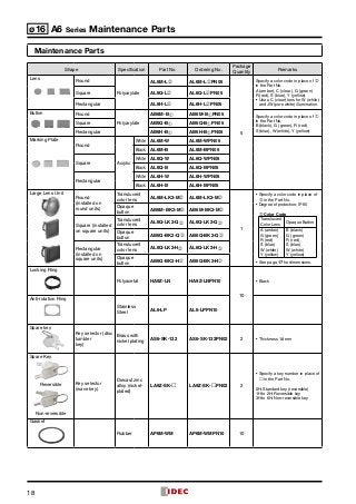
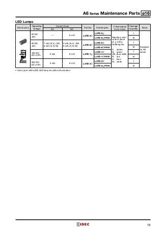
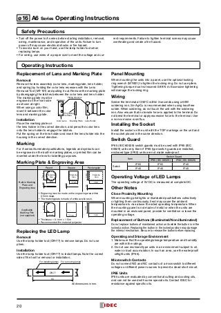
A Series
Switches & Pilot Lights
Tư vấn chọn sản phẩm
Giao hàng tận nơi
Hỗ trợ kỹ thuật
Chính sách hậu mãi đa dạng
DỊCH VỤ CHĂM SÓC KHÁCH HÀNG TOÀN DIỆN
Nhà cung cấp thiết bị điện chuyên nghiệp
Hotline: 0904.676.925
CÔNG TY TNHH THƯƠNG MẠI KỸ THUẬT ASTER
Số 7 Đại lộ Độc Lập, KCN Sóng Thần,
P. Dĩ An, Tx. Dĩ An, Bình Dương, VN.
Tel: (0650) 3617 012
Fax: (0650) 3617 011
www.beeteco.com
2
ø16 ø12 ø10 ø8 A Series Selection Guide
Series A6 Series Switches and Pilot Lights
Mounting Hole Size ø16
Model AL6 AB6 AS6 AS6 (key)
Shape
Disc tumbler key
Wave key
Unit
Illuminated Push­buttons
(Momen­tary, Maintained)
Pilot Light
Pushbuttons (Momentary,
Main­tained)
Selector Switch
(90° 2-position
maintained,
90° 2-position spring
return,
45° 3-position main­
tained,
45° 3-position spring
return)
Key Selector Switch
(90° 2-position
maintained,
90° 2-position spring
return,
45° 3-position main­
tained,
45° 3-position spring
return)
Bezel Size (mm) 18 × 2418ø18 18 × 2418ø18
Bezel Color Black
Light Source
LED Lamp
(IDEC’s LATD)
— — —
Button/Illumination
Color
Illumination: amber, blue,
green, pure white, red,
white, yellow
Button: black, blue,
green, red, white, yellow
Lens: amber, blue, green,
red, yellow, white
Knob: black
Key cylinder: chrome
plating (metal)
Contact
Contact
Configuration
SPDT, DPDT (Gold-clad silver contact)
Contact Rating
(resistive load)
110V AC/1A, 24V DC/1A
Durability
Electrical
Momentary:	100,000 operations minimum
Maintained:	  50,000 operations minimum
100,000 operations minimum
Mechanical
Momentary:	1,000,000 operations minimum
Maintained:	  100,000 operations minimum
250,000 operations minimum
Degree of Protection IP65, IP40 (IEC 60529)
Terminal Style Solder terminal
Accessories
Switch Guard Yes Yes — —
Socket Yes Yes Yes Yes
Terminal Cover Yes Yes Yes Yes
Dust Cover Yes Yes — —
Mounting Hole Plug Yes Yes Yes Yes
Remarks
•	LED lamps contain a
current-limiting resistor
and a pro­tection diode.
•	Available with three-
sided barrier.
•	Available with three-
sided barrier.
•	Operator position can be changed by IDEC’s
original bezel rotating and locking system.
Approvals
Page 5 8 10 11
3
A Series Selection Guide ø16 ø12 ø10 ø8
Series A Series Switches and Pilot Lights
Mounting Hole Size ø12 ø10 ø8
Model AL2 AB2 AL1 AB1 AL8 AB8
Shape
Unit
•	Illuminated
Pushbuttons
(Momentary,
Maintained)
•	Pilot Light
•	Pushbuttons
(Momentary,
Maintained)
•	Illuminated
Pushbuttons
(Momentary,
Maintained)
•	Pilot Light
•	Pushbuttons
(Momentary,
Maintained)
•	Illuminated
Pushbuttons
(Momentary,
Maintained)
•	Pilot Light
•	Pushbuttons
(Momentary,
Maintained)
Bezel Size (mm) 14 × 1814ø14 12 × 1612ø12 9 × 129ø9
Bezel Color Black Black Black
Light Source
LED lamp
(IDEC’s LAD-S)
—
LED lamp
(IDEC’s LAD-S)
—
LED lamp
(IDEC’s LAD-S)
—
Button/Illumination
Color
Illumination:
amber, green,
red, white, yellow
Button: black,
blue, green, red,
white, yellow
Lens: amber,
blue, green, red,
yellow, white
Illumination:
amber, green,
red, white, yellow
Button: black,
blue, green, red,
white, yellow
Lens: amber,
blue, green, red,
yellow, white
Illumination:
amber, green,
red, white, yellow
Button: black,
blue, green, red,
white, yellow
Lens: amber,
blue, green, red,
yellow, white
Contact
Contact
Configuration
SPDT, DPDT (silver contact) SPDT (silver contact) SPDT (silver contact)
Contact Rating
(resistor load)
110V AC/1A, 24V DC/1A 110V AC/1A, 24V DC/1A 110V AC/1A, 24V DC/1A
Durability
Electrical
Momentary:
100,000 operations minimum
Maintained:
50,000 operations minimum
Momentary:
100,000 operations minimum
Maintained:
50,000 operations minimum
Momentary:
100,000 operations minimum
Maintained:
50,000 operations minimum
Mechanical
Momentary:
200,000 operations minimum
Maintained:
100,000 operations minimum
Momentary:
200,000 operations minimum
Maintained:
100,000 operations minimum
Momentary:
200,000 operations minimum
Maintained:
100,000 operations minimum
Degree of
Protection
IP65, IP40 (IEC 60529) IP40 (IEC 60529) IP40 (IEC 60529)
Terminal Style Solder terminal Solder terminal Solder terminal
Accessories
Switch Guard Yes Yes Yes
Socket Yes Yes Yes
Terminal Cover Yes Yes Yes
Dust Cover Yes — —
Mounting Hole
Plug
Yes Yes Yes
Remarks
•	External current-limiting resistor
type (Note)
•	External current-limiting resistor
type (Note)
•	External current-limiting resistor
type (Note)
Approvals
(except for pilot lights) (except for pilot lights) (except for pilot lights)
Page 22 23 29 30 35 36
Note: LED lamps do not contain a current-limiting resistor, and external resistors must be connected.
4
ø16 A6 Series Switches and Pilot Lights
Light duty in short 22mm body length.
•• Features IDEC’s original mechanism for snap-action
switching. Suitable for a wide variety of office and factory
aplications.
•• The LED lamp contains a current-limiting resistor and a
diode for protection against reverse connection.
•• Degree of protection: IP40 and IP65 (IEC 60529)
•• UL recognized, CSA certified, EN compliant, and CCC
approved.
Applicable Standards Mark File No. or Organization
UL508
UL Recognition
File No. E55996
CSA C22.2 No.14 CSA File No. LR 21451
EN60947-5-1 EU Low Voltage Directive
GB14048.5
CCC
2003010305027381 (switches)
2008010304288772 (pilot lights)
LED Lamp Ratings (LATD)
Part No. LATD-5➁ LATD-1➁ LATD-2➁
Lamp Base Exclusive for A series
Voltage Range 5V DC ±5% 12V AC/DC ±10% 24V AC/DC ±10%
Rated Voltage 5V DC 12V AC/DC 24V AC/DC
Current Draw
AC — 9 mA 9 mA
DC 8 mA 8 mA 8 mA
Color Code ➁ A (amber), G (green), JW (pure white), R (red), S (blue), W (white)
Lamp Base Color Same as illumination color (except JW - gray base)
Voltage Marking Die stamped on the base
Life (reference value)
Approx. 50,000 hours
(The luminance is reduced to 50% of the initial intensity when used on complete DC.)
Internal Circuit
•	Specify a color code in place of ➁ in the Part No.
A (amber), G (green), JW (pure white), R (red), S (blue), W (white)
•	Use a pure white (JW) LED lamp for yellow illumination.
Contact Ratings (Contact Block)
Rated Insulation Voltage 250V
Rated Thermal Current 3A
Operating Voltage (AC/DC) 12V 24V 110V 220V
AC 50/60 Hz
Resistive Load – – 1.0A 0.5A
Inductive Load – – 0.7A 0.5A
DC
Resistive Load 1.0A 1.0A 0.2A –
Inductive Load 0.7A 0.7A 0.5A –
Contact Material Gold-clad silver
•	Minimum applicable load: 5V AC/DC, 1 mA
(applicable range may vary with operating conditions and load
types)
Weight (example)
Weight (approx.)
AL6M-M24:	 8g
AL6M-M221:	46g
AL6M-P4:	 6g
AL6M-P21:	45g
AB6M-M2:	 7g
AS6M-2Y2:	 9g
AS6M-2KT2A:	21g
Specifications
Operating Temperature –25 to +55°C (no freezing)
Storage Temperature –30 to +80°C (no freezing)
Operating Humidity 45 to 85% RH (no condensation)
Contact Resistance 50 mΩ maximum (initial value)
Insulation Resistance 100 MΩ minimum (500V DC megger)
Dielectric
Strength
Switch
Unit
Between live and dead metal parts:
	 2,000V AC, 1 minute
Between terminals of different poles:
	 2,000V AC, 1 minute
Between terminals of the same pole:
	 1,000V AC, 1 minute
Between contact and lamp terminals:
	 1,500V AC, 1 minute
Illumination
Unit
Between live part and ground:
	 2,000V AC, 1 minute
Vibration Resistance
Operating extremes:	
5 to 55 Hz, amplitude 0.75 mm
Shock Resistance
Damage limits:	 500 m/s2
(50G)
Operating extremes:	 200 m/s2
(20G)
Mechanical Durability
(minimum
operations)
Momentary:	 1,000,000 operations
Maintained:	  100,000 operations
Pushlock Turn Reset:	  100,000 operations
Selector Switch:	  250,000 operations
Key Selector Switch:	  250,000 operations
Electrical Durability
(minimum
operations)
Other than Maintained:	100,000 operations
Maintained:	  50,000 operations
(Switching frequency 1200 operations/h)
Degree of Protection IP40, IP65 (IEC 60529)
Terminal Style Solder terminal
(+) (–) LED Chip
Protection Diode
Zener Diode
5
A6 Series Illuminated Pushbuttons ø16
Illuminated Pushbuttons
 Package Quantity: 1
Shape Operation
Operating
Voltage
Contact
Part No. ➁ Illumination
Color CodeIP40 IP65
Round
AL6M
Momentary
5V DC ±5%
SPDT AL6M-M11➁ AL6M-M11P➁
Specify a color code
in place of ➁ in the
Part No.
A:	amber
G:	green
JW:	pure white
R:	red
S:	blue
W:	white
Y:	yellow
DPDT AL6M-M21➁ AL6M-M21P➁
12V AC/DC
±10%
SPDT AL6M-M13➁ AL6M-M13P➁
DPDT AL6M-M23➁ AL6M-M23P➁
24V AC/DC
±10%
SPDT AL6M-M14➁ AL6M-M14P➁
DPDT AL6M-M24➁ AL6M-M24P➁
Maintained
5V DC ±5%
SPDT AL6M-A11➁ AL6M-A11P➁
DPDT AL6M-A21➁ AL6M-A21P➁
12V AC/DC
±10%
SPDT AL6M-A13➁ AL6M-A13P➁
DPDT AL6M-A23➁ AL6M-A23P➁
24V AC/DC
±10%
SPDT AL6M-A14➁ AL6M-A14P➁
DPDT AL6M-A24➁ AL6M-A24P➁
Square
AL6Q
Momentary
5V DC ±5%
SPDT AL6Q-M11➁ AL6Q-M11P➁
DPDT AL6Q-M21➁ AL6Q-M21P➁
12V AC/DC
±10%
SPDT AL6Q-M13➁ AL6Q-M13P➁
DPDT AL6Q-M23➁ AL6Q-M23P➁
24V AC/DC
±10%
SPDT AL6Q-M14➁ AL6Q-M14P➁
DPDT AL6Q-M24➁ AL6Q-M24P➁
Maintained
5V DC ±5%
SPDT AL6Q-A11➁ AL6Q-A11P➁
DPDT AL6Q-A21➁ AL6Q-A21P➁
12V AC/DC
±10%
SPDT AL6Q-A13➁ AL6Q-A13P➁
DPDT AL6Q-A23➁ AL6Q-A23P➁
24V AC/DC
±10%
SPDT AL6Q-A14➁ AL6Q-A14P➁
DPDT AL6Q-A24➁ AL6Q-A24P➁
Rectangular
AL6H
Momentary
5V DC ±5%
SPDT AL6H-M11➁ AL6H-M11P➁
DPDT AL6H-M21➁ AL6H-M21P➁
12V AC/DC
±10%
SPDT AL6H-M13➁ AL6H-M13P➁
DPDT AL6H-M23➁ AL6H-M23P➁
24V AC/DC
±10%
SPDT AL6H-M14➁ AL6H-M14P➁
DPDT AL6H-M24➁ AL6H-M24P➁
Maintained
5V DC ±5%
SPDT AL6H-A11➁ AL6H-A11P➁
DPDT AL6H-A21➁ AL6H-A21P➁
12V AC/DC
±10%
SPDT AL6H-A13➁ AL6H-A13P➁
DPDT AL6H-A23➁ AL6H-A23P➁
24V AC/DC
±10%
SPDT AL6H-A14➁ AL6H-A14P➁
DPDT AL6H-A24➁ AL6H-A24P➁
Rectangular
w/three-sided barrier
AL6G
Momentary
5V DC ±5%
SPDT AL6G-M11➁ AL6G-M11P➁
DPDT AL6G-M21➁ AL6G-M21P➁
12V AC/DC
±10%
SPDT AL6G-M13➁ AL6G-M13P➁
DPDT AL6G-M23➁ AL6G-M23P➁
24V AC/DC
±10%
SPDT AL6G-M14➁ AL6G-M14P➁
DPDT AL6G-M24➁ AL6G-M24P➁
Maintained
5V DC ±5%
SPDT AL6G-A11➁ AL6G-A11P➁
DPDT AL6G-A21➁ AL6G-A21P➁
12V AC/DC
±10%
SPDT AL6G-A13➁ AL6G-A13P➁
DPDT AL6G-A23➁ AL6G-A23P➁
24V AC/DC
±10%
SPDT AL6G-A14➁ AL6G-A14P➁
DPDT AL6G-A24➁ AL6G-A24P➁
•	See page 7 for dimensions.
•	See page 20 for marking plate size and engraving area.
•	When using white lens unit (clear lens + white marking plate) with color codes A, G, R, or S, specify “W” before ➁ in the Part No. (without
CCC marking) Example: AL6H-M24W➁
•	A pure white (JW) LED lamp is used for yellow illumination.
6
ø16 A6 Series Pilot Lights
Pilot Lights
 Package Quantity: 1
Shape Operating Voltage
Part No. ➁ Illumination
Color CodeIP40 IP65
Round
AL6M-P
5V DC ±5% AL6M-P1➁ AL6M-P1P➁
Specify a color code in
place of ➁ in the Part No.
A:	amber
G:	green
JW:	pure white
R:	red
S:	blue
W:	white
Y:	yellow
12V AC/DC ±10% AL6M-P3➁ AL6M-P3P➁
24V AC/DC ±10% AL6M-P4➁ AL6M-P4P➁
Square
AL6Q-P
5V DC ±5% AL6Q-P1➁ AL6Q-P1P➁
12V AC/DC ±10% AL6Q-P3➁ AL6Q-P3P➁
24V AC/DC ±10% AL6Q-P4➁ AL6Q-P4P➁
Rectangular
AL6H-P
5V DC ±5% AL6H-P1➁ AL6H-P1P➁
12V AC/DC ±10% AL6H-P3➁ AL6H-P3P➁
24V AC/DC ±10% AL6H-P4➁ AL6H-P4P➁
Rectangular w/three-sided barrier
AL6G-P
5V DC ±5% AL6G-P1➁ AL6G-P1P➁
12V AC9DC ±10% AL6G-P3➁ AL6G-P3P➁
24V AC/DC ±10% AL6G-P4➁ AL6G-P4P➁
•	See page 7 for dimensions.
•	See page 20 for marking plate size and engraving area.
•	When using white lens unit (clear lens + white marking plate) with color codes A, G, R, or S, specify “W” before ➁ in the Part No.
(without CCC marking) Example: AL6H-M24W➁
•	A pure white (JW) LED lamp is used for yellow illumination.
7
A6 Series Illuminated Pushbuttons and Pilot Lights Dimensions ø16
Dimensions (Illuminated Pushbuttons  Pilot Lights)
Anti-rotation Ring
Rubber Gasket
Locking Ring
(TOP)
Rectangular
Rectangular w/3-way barrier
Round
(TOP)
Square
(TOP)
Terminal Width 2.8×0.5t Panel Thickness 0.5 to 6
5.7
9
1824
18
1 0.6
8 22 9
2.5 3
55
6 6
Illuminated PushbuttonPilot Light
ø18
Terminal Arrangement (bottom view)
Mounting Hole Layout
NC1
NO1
C1
NC2
NO2
C2
Lamp
Terminal (+)
Lamp
Terminal (–)
(TOP)
Lamp
Terminal (+)
Lamp
Terminal (–)
(TOP)
Illuminated Pushbutton Pilot Light
ø16.2 0
+0.2
18 min.
18min.
ø16.2 0
+0.2
24 min.
18min.
Round/Square Rectangular
Rectangular w/3-way barrier
All dimensions in mm.
Note:	 Determine mounting
centers to ensure
easy operation.
8
ø16 A6 Series Pushbuttons
Pushbuttons
 Package Quantity: 1
Shape Button Style Operation Contact
Part No.
Color Code ➀➁IP40 IP65
Round
AB6M
Button
Momentary
SPDT AB6M-M1➀ AB6M-M1P➀ B	black
G:	green
R:	red
S:	blue
W:	white
Y:	yellow
DPDT AB6M-M2➀ AB6M-M2P➀
Maintained
SPDT AB6M-A1➀ AB6M-A1P➀
DPDT AB6M-A2➀ AB6M-A2P➀
Lens
Momentary
SPDT AB6M-M1L➁ AB6M-M1PL➁ A:	amber
G:	green
R:	red
S:	blue
W:	white
Y:	yellow
DPDT AB6M-M2L➁ AB6M-M2PL➁
Maintained
SPDT AB6M-A1L➁ AB6M-A1PL➁
DPDT AB6M-A2L➁ AB6M-A2PL➁
Square
AB6Q
Button
Momentary
SPDT AB6Q-M1➀ AB6Q-M1P➀ B	black
G:	green
R:	red
S:	blue
W:	white
Y:	yellow
DPDT AB6Q-M2➀ AB6Q-M2P➀
Maintained
SPDT AB6Q-A1➀ AB6Q-A1P➀
DPDT AB6Q-A2➀ AB6Q-A2P➀
Lens
Momentary
SPDT AB6Q-M1L➁ AB6Q-M1PL➁ A:	amber
G:	green
R:	red
S:	blue
W:	white
Y:	yellow
DPDT AB6Q-M2L➁ AB6Q-M2PL➁
Maintained
SPDT AB6Q-A1L➁ AB6Q-A1PL➁
DPDT AB6Q-A2L➁ AB6Q-A2PL➁
Rectangular
AB6H
Button
Momentary
SPDT AB6H-M1➀ AB6H-M1P➀ B	black
G:	green
R:	red
S:	blue
W:	white
Y:	yellow
DPDT AB6H-M2➀ AB6H-M2P➀
Maintained
SPDT AB6H-A1➀ AB6H-A1P➀
DPDT AB6H-A2➀ AB6H-A2P➀
Lens
Momentary
SPDT AB6H-M1L➁ AB6H-M1PL➁ A:	amber
G:	green
R:	red
S:	blue
W:	white
Y:	yellow
DPDT AB6H-M2L➁ AB6H-M2PL➁
Maintained
SPDT AB6H-A1L➁ AB6H-A1PL➁
DPDT AB6H-A2L➁ AB6H-A2PL➁
Rectangular
w/three-sided barrier
AB6G Button
Momentary
SPDT AB6G-M1➀ AB6G-M1P➀ B	black
G:	green
R:	red
S:	blue
W:	white
Y:	yellow
DPDT AB6G-M2➀ AB6G-M2P➀
Maintained
SPDT AB6G-A1➀ AB6G-A1P➀
DPDT AB6G-A2➀ AB6G-A2P➀
Lens
Momentary
SPDT AB6G-M1L➁ AB6G-M1PL➁ A:	amber
G:	green
R:	red
S:	blue
W:	white
Y:	yellow
DPDT AB6G-M2L➁ AB6G-M2PL➁
Maintained
SPDT AB6G-A1L➁ AB6G-A1PL➁
DPDT AB6G-A2L➁ AB6G-A2PL➁
•	Specify a color code in place of ➀ or ➁ in the Part No.
•	See page 9 for dimensions.
•	See page 20 for marking plate size and engraving area.
•	Black is available for lens style buttons. Black lens consists of a clear lens and a black marking plate. Specify “B” in place of ➁ in the Part
No.
Example:AB6H-M2LB
9
A6 Series Pushbuttons ø16
Dimensions
Mounting Hole Layout	Terminal Arrangement
(bottom view)
ø16.2 0
+0.2
18 min.
18min.
ø16.2 0
+0.2
24 min.
18min.
NC1
NO1
C1
NC2
NO2
C2
(TOP)
Round/Square Rectangular
Rectangular Pushbutton
w/3-way barrier
Note:	 Determine mounting
centers to ensure
easy operation.
All dimensions in mm.
Note:	 SPDT has only
NC1, NO1, and
C1 terminals.
Anti-rotation Ring
Rubber Gasket
Locking Ring
ø18
(TOP)
Rectangular
Rectangular w/3-way barrier
Round
(TOP)
Square
(TOP)
Terminal Width 2.8×0.5t
5.7
9
1824
18
1 0.6
8 22 9
Panel Thickness 0.5 to 6
2.5 3
55
Pushbutton
10
ø16 A6 Series Selector Switches
Selector Switches
Dimensions
RL
(C)
R
L
(C)
R
L
(C)
L
R
(C)
Operator position can be changed by IDEC’s original bezel rotating and
locking system. The bezel can be locked at every 45° and bezel rotation
is prevented while mounting on a panel.
How to change the operator position
Pull out the bezel to release the lock. Rotate the bezel, and
push it in at 45° intervals to lock the bezel.
Example: 3-position
Normal Operator Position
 Package Quantity: 1
Shape Position Contact
Part No.
IP40 IP65
Round
AS6M-Y
90°
2-position
Maintained
SPDT AS6M-2Y1 AS6M-2Y1P
DPDT AS6M-2Y2 AS6M-2Y2P
Spring return from
right to left
SPDT AS6M-21Y1 AS6M-21Y1P
DPDT AS6M-21Y2 AS6M-21Y2P
45°
3-position
Maintained DPDT AS6M-3Y2 AS6M-3Y2P
Spring return from
right to center
DPDT AS6M-31Y2 AS6M-31Y2P
Spring return from left
to center
DPDT AS6M-32Y2 AS6M-32Y2P
Spring return two-way DPDT AS6M-33Y2 AS6M-33Y2P
Square
AS6Q-Y
90°
2-position
Maintained
SPDT AS6Q-2Y1 AS6Q-2Y1P
DPDT AS6Q-2Y2 AS6Q-2Y2P
Spring return from
right to left
SPDT AS6Q-21Y1 AS6Q-21Y1P
DPDT AS6Q-21Y2 AS6Q-21Y2P
45°
3-position
Maintained DPDT AS6Q-3Y2 AS6Q-3Y2P
Spring return from
right to center
DPDT AS6Q-31Y2 AS6Q-31Y2P
Spring return from left
to center
DPDT AS6Q-32Y2 AS6Q-32Y2P
Spring return two-way DPDT AS6Q-33Y2 AS6Q-33Y2P
Rectangular
AS6H-Y
90°
2-position
Maintained
SPDT AS6H-2Y1 AS6H-2Y1P
DPDT AS6H-2Y2 AS6H-2Y2P
Spring return from
right to left
SPDT AS6H-21Y1 AS6H-21Y1P
DPDT AS6H-21Y2 AS6H-21Y2P
45°
3-position
Maintained DPDT AS6H-3Y2 AS6H-3Y2P
Spring return
from right to center
DPDT AS6H-31Y2 AS6H-31Y2P
Spring return
from left to center
DPDT AS6H-32Y2 AS6H-32Y2P
Spring return two-way DPDT AS6H-33Y2 AS6H-33Y2P
•	Bezel: black	 •	 Knob: black
Contact Operation
Position Operation Left Center Right
90°2-position
Spring
return from
right
right
Maintained
L R
L R
SPDT
NO
C
NC
—
NO
C
NC
DPDT
Left
Contact
NO
C
NC
Right
Contact
NO
C
NC
—
NO
C
NC NO
C
NC
Left
Contact
Right
Contact
45°3-position
C
L R
L
C
R
L
C
R
Maintained
Spring
return from
right
Spring
return from
left
Two-way
return
C
RL
DPDT
NO
C
NC NO
C
NC
Left
Contact
Right
Contact
Left
Contact
NO
C
NC
Right
Contact
NO
C
NC NO
C
NC NO
C
NC
Left
Contact
Right
Contact
Terminal Width 2.8×0.5t
Anti-rotation Ring
Rubber Gasket
Locking Ring
Rectangular
(TOP)
Round
(TOP)
Square
(TOP)2.5 3
55
Panel Thickness 0.5 to 6
1
8 22 15.5 24
18
c18
8
ø18
NC1
NO1
C1
NC2
NO2
C2
(TOP)
Terminal Arrangement (bottom view)
(Selector Switch)
SPDT has NC1, NO1, and C1 only.
ø16.2 0
+0.2
18 min.
18min.
ø16.2 0
+0.2
24 min.
18min.
Mounting Hole Layout
Round/Square Rectangular
Note: Determine mounting centers to ensure easy operation. All dimensions in mm.
11
A6 Series Key Selector Switches ø16
Key Selector Switches
 Package Quantity: 1
Shape Position Operation
Key Retained
at ●
Contact
Part No.
IP40 IP65
Round
AS6M
Disc tumbler key
Wave key
90°
2-position
Maintained
A
L R SPDT AS6M-2K1A AS6M-2K1PA
DPDT AS6M-2K2A AS6M-2K2PA
B
L R SPDT AS6M-2K1B AS6M-2K1PB
DPDT AS6M-2K2B AS6M-2K2PB
C
L R SPDT AS6M-2K1C AS6M-2K1PC
DPDT AS6M-2K2C AS6M-2K2PC
Spring return from right B
L R SPDT AS6M-21K1B AS6M-21K1PB
DPDT AS6M-21K2B AS6M-21K2PB
45°
3-position
Maintained
A
L
C
R DPDT
AS6M-3K2A AS6M-3K2PA
B
L
C
R DPDT
AS6M-3K2B AS6M-3K2PB
C
C
RL DPDT
AS6M-3K2C AS6M-3K2PC
D
C
RL DPDT
AS6M-3K2D AS6M-3K2PD
E
L R
C DPDT
AS6M-3K2E AS6M-3K2PE
G
L
C
R DPDT
AS6M-3K2G AS6M-3K2PG
H
C
L R DPDT
AS6M-3K2H AS6M-3K2PH
Spring return from right
B
C
L R DPDT
AS6M-31K2B AS6M-31K2PB
D
C
RL DPDT
AS6M-31K2D AS6M-31K2PD
G
L
C
R DPDT
AS6M-31K2G AS6M-31K2PG
Spring return from left
C
C
RL DPDT
AS6M-32K2C AS6M-32K2PC
D
C
RL DPDT
AS6M-32K2D AS6M-32K2PD
H
C
L R DPDT
AS6M-32K2H AS6M-32K2PH
Spring return two-way D
C
RL DPDT
AS6M-33K2D AS6M-33K2PD
•	Specify the key code in place of  in the Part No.: T (disc tumbler key), S (wave key)
•	For contact operation, see page 14.
•	Key is retained at ● positions and removable at  positions.
•	Two keys are supplied.
•	The front of key cylinder is made of metal.
•	For disc tumbler key, only one type of key is available.
•	For wave key, besides the standard key (key number 0H), six other keys are also available.
To order other keys, specify the key number as shown below:
Note:
Key number is indicated on the key cylinder.
Standard keys do not have a key number indication.
Example: AS6M-2KS1PA-1H
	 (blank):	 Standard key (0H)
	 1H to 2H:	 Reversible key
	 3H to 6H:	 Non-reversible key
12
ø16 A6 Series Key Selector Switches
Key Selector Switches
 Package Quantity: 1
Shape Position Operation
Key Retained
at ●
Contact
Part No.
IP40 IP65
Square
AS6Q
Disc tumbler key
Wave key
90°
2-position
Maintained
A
L R SPDT AS6Q-2K1A AS6Q-2K1PA
DPDT AS6Q-2K2A AS6Q-2K2PA
B
L R SPDT AS6Q-2K1B AS6Q-2K1PB
DPDT AS6Q-2K2B AS6Q-2K2PB
C
L R SPDT AS6Q-2K1C AS6Q-2K1PC
DPDT AS6Q-2K2C AS6Q-2K2PC
Spring return from right B
L R SPDT AS6Q-21K1B AS6Q-21K1PB
DPDT AS6Q-21K2B AS6Q-21K2PB
45°
3-position
Maintained
A L
C
R
DPDT AS6Q-3K2A AS6Q-3K2PA
B
L
C
R
DPDT AS6Q-3K2B AS6Q-3K2PB
C
C
RL
DPDT AS6Q-3K2C AS6Q-3K2PC
D
C
RL
DPDT AS6Q-3K2D AS6Q-3K2PD
E
L R
C
DPDT AS6Q-3K2E AS6Q-3K2PE
G
L
C
R
DPDT AS6Q-3K2G AS6Q-3K2PG
H
C
L R
DPDT AS6Q-3K2H AS6Q-3K2PH
Spring return from right
B
C
L R
DPDT AS6Q-31K2B AS6Q-31K2PB
D
C
RL
DPDT AS6Q-31K2D AS6Q-31K2PD
G
L
C
R
DPDT AS6Q-31K2G AS6Q-31K2PG
Spring return from left
C
C
RL
DPDT AS6Q-32K2C AS6Q-32K2PC
D
C
RL
DPDT AS6Q-32K2D AS6Q-32K2PD
H
C
L R
DPDT AS6Q-32K2H AS6Q-32K2PH
Spring return two-way D
C
RL
DPDT AS6Q-33K2D AS6Q-33K2PD
•	Specify the key code in place of  in the Part No.: T (disc tumbler key), S (wave key)
•	For contact operation, see page 14.
•	Key is retained at ● positions and removable at  positions.
•	Two keys are supplied.
•	The front of key cylinder is made of metal.
•	For disc tumbler key, only one type of key is available.
•	For wave key, besides the standard key (key number 0H), six other keys are also available.
To order other keys, specify the key number as shown below:
Note:
Key number is indicated on the key cylinder.
Standard keys do not have a key number indication.
Example: AS6M-2KS1PA-1H
	 (blank):	 Standard key (0H)
	 1H to 2H:	 Reversible key
	 3H to 6H:	 Non-reversible key
13
A6 Series Key Selector Switches ø16
Key Selector Switches
 Package Quantity: 1
Shape Position Operation
Key Retained
at ●
Contact
Part No.
IP40 IP65
Rectangular
AS6H
Disc tumbler key
Wave key
90°
2-position
Maintained
A
L R SPDT AS6H-2K1A AS6H-2K1PA
DPDT AS6H-2K2A AS6H-2K2PA
B
L R SPDT AS6H-2K1B AS6H-2K1PB
DPDT AS6H-2K2B AS6H-2K2PB
C
L R SPDT AS6H-2K1C AS6H-2K1PC
DPDT AS6H-2K2C AS6H-2K2PC
Spring return from right B
L R SPDT AS6H-21K1B AS6H-21K1PB
DPDT AS6H-21K2B AS6H-21K2PB
45°
3-position
Maintained
A L
C
R
DPDT AS6H-3K2A AS6H-3K2PA
B
L
C
R
DPDT AS6H-3K2B AS6H-3K2PB
C
C
RL
DPDT AS6H-3K2C AS6H-3K2PC
D
C
RL
DPDT AS6H-3K2D AS6H-3K2PD
E
L R
C
DPDT AS6H-3K2E AS6H-3K2PE
G
L
C
R
DPDT AS6H-3K2G AS6H-3K2PG
H
C
L R
DPDT AS6H-3K2H AS6H-3K2PH
Spring return from right
B
C
L R
DPDT AS6H-31K2B AS6H-31K2PB
D
C
RL
DPDT AS6H-31K2D AS6H-31K2PD
G
L
C
R
DPDT AS6H-31K2G AS6H-31K2PG
Spring return from left
C
C
RL
DPDT AS6H-32K2C AS6H-32K2PC
D
C
RL
DPDT AS6H-32K2D AS6H-32K2PD
H
C
L R
DPDT AS6H-32K2H AS6H-32K2PH
Spring return two-way D
C
RL
DPDT AS6H-33K2D AS6H-33K2PD
•	Specify the key code in place of  in the Part No.: T (disc tumbler key), S (wave key)
•	For contact operation, see page 14.
•	Key is retained at ● positions and removable at  positions.
•	Two keys are supplied.
•	The front of key cylinder is made of metal.
•	For disc tumbler key, only one type of key is available.
•	For wave key, besides the standard key (key number 0H), six other keys are also available.
To order other keys, specify the key number as shown below:
Note:
Key number is indicated on the key cylinder.
Standard keys do not have a key number indication.
Example: AS6M-2KS1PA-1H
	 (blank):	 Standard key (0H)
	 1H to 2H:	 Reversible key
	 3H to 6H:	 Non-reversible key
14
ø16 A6 Series Key Selector Switches
Contact Operation
Operator Position  Contact Operation (Top View)
Positions Contact Left Center Right
90° 2-position
SPDT
NO
C
NC
—
NO
C
NC
DPDT
Left
Contact
NO
C
NC
Right
Contact
NO
C
NC
—
NO
C
NC NO
C
NC
Left
Contact
Right
Contact
45° 3-position
RL
C
RL
C
L
C
R
C
RL
Maintained Spring return
from right
Spring return
from left
Spring return
two-way
DPDT
NO
C
NC NO
C
NC
Left
Contact
Right
Contact
Left
Contact
NO
C
NC
Right
Contact
NO
C
NC NO
C
NC NO
C
NC
Left
Contact
Right
Contact
Dimensions
Disc Tumbler Key
Wave Key
Terminal Arrangement (bottom view)
(Key Selector Switch)
NC1
NO1
C1
NC2
NO2
C2
(TOP)
SPDT has NC1, NO1, and C1 only.
Mounting Hole Layout
ø16.2 0
+0.2
18 min.
18min.
Round/Square
ø16.2 0
+0.2
24 min.
18min.
Rectangular
Note: Determine
mounting centers
to ensure easy
operation.
L R RL
Maintained Spring return from right
All dimensions in mm.
2.6
2-R0.6
1.0
1.2
Anti-rotation Ring
Rubber Gasket
Locking Ring
Terminal Width 2.8×0.5t
C
NC
NO
2.5 3
55
Panel Thickness 0.5 to 6
1
9
8 22 26
(TOP)
Round Square
(TOP)
Rectangular
(TOP)
2418
18
ø18
Left Contact
Right Contact
TOP
32.5
31.3
10.2
32.5
Panel thickness 0.5 to 6
55
1
8
0.6
22
Key No.: 3H to 6H
Key No.: 0H to 2H
Anti-rotation Ring
Locking Ring
Gasket
SPDT DPDT
SPDT DPDT
Terminal Width 2.8×0.5t 18
24
18ø18
ø18 18
24
18Round/Square Round Square Rectangular
Rectangular
TOP
NC
NO
C
NC
NO
C
NC
NO
C
NC
NO
C
15
A6 Series Accessories ø16
Accessories
Shape Material Part No.
Ordering
No.
Package
Quantity
Remarks
Locking Ring Wrench
Metal
(nickel-plated
brass)
MT-001 MT-001 1
•	Used to tighten the locking ring when
installing A6 series into a panel.
Lamp Holder Tool
Rubber OR-77 OR-77 1
•	Used to install and remove the LED
lamps.
Lens Removal Tool
Stainless
Steel
MT-101 MT-101 1
•	Used to install and remove lenses and
buttons.
Switch Guard For round/
square
units
(remains
90° open)
Guard
(polyarylate)
Base
(polyacetal)
See page
16 for
dimen­sions.
AL-K6 AL-K6 1
•	Degree of protection: IP40
•	Used to protect pushbuttons from
inadvertent operation.
For rectan­
gular units
(remains
110° open)
AL-KH6 AL-KH6 1
For round/
square
units (180°
spring
return)
Spring
Return
AL-K6S AL-K6S 1
AL-K6SP AL-K6SP 1
•	Degree of protection: IP65 (when used
with IP65 units)
•	Used to protect pushbuttons from
inadvertent operation.
For rectan­
gular units
(180°
spring
return)
AL-KH6S AL-KH6S 1
•	Degree of protection: IP40
•	Used to protect pushbuttons from
inadvertent operation.
AL-
KH6SP
AL-KH6SP 1
•	Degree of protection: IP65 (when used
with IP65 units)
•	Used to protect pushbuttons from
inadvertent operation.
Dust Cover For round
units Translucent
cover:
elastomer
Black part:
polypropylene
AL-D6 AL-D6 1
•	When mounting the units with the dust
covers installed, refer to mounting hole
layout on page 17.
•	Operating temperature: –10 to +55°C
For square
units
AL-DQ6 AL-DQ6 1
For rectan­
gular units
AL-DH6 AL-DH6 1
Terminal Cover
Polyamide
(white)
See page
17 for
dimen­sions.
AL-V6 AL-V6PN10 10
•	When wiring the terminals, insert the
lead wires into the terminal cover holes
before soldering.
•	Terminal cover is not attached and
must be ordered separately.
Socket Solder
Terminal See page
17 for
dimen­sions.
AL-C6 AL-C6 1
•	Plugs on the rear of the A series.
PC Board
Terminal
AL-C6V AL-C6V 1
Mounting Hole Plug
Rubber
Nitryl rubber
(black)
AL-B6 AL-B6PN05 5
•	Degree of protection: IP65
Mounting Hole Plug
Metal
Plug: metal
(diecast)
Locking ring:
polyacetal
Gasket: nitrile
AL-BM6 AL-BM6 1
•	Degree of protection: IP65
•	Tightening torque: 0.1 to 0.29 N·m.
ø18
60
ø9
55
ø10
60
2 6
ø16.5
ø18
0
+0.2
ø16.2
Mounting Hole
0
+0.2
ø16.2
Mounting Hole
Locking RingGasket
2.5 12
ø17.8
Panel Thickness 0.5 to 6
All dimensions in mm.
16
ø16 A6 Series Accessories
Dimensions
Switch Guard (Degree of protection: IP40)
(180° opening)
(45.5minimumfor180°opening)
Rubber Gasket
34
33
14 28
Panel Thickness
0.5 to 5
R22
24
10.513
23.5
26.5minimum
26.5minimum
25 minimum
1310.5
23.5
19 minimum
18
(AL-K6S) (AL-KH6S)
Switch Guard (Degree of protection: IP65)
Panel Thickness
0.5 to 5
Rubber
Gasket
Waterproof Gasket
for Switch Guard
34
33
14 28
R22
24
10.513
23.5
45.5min.
25 min.
1310.5
23.5
19 min.
45.5min.
18
0.4
For Round/Square Units
(AL-K6SP)
For Rectangular Units
(AL-KH6SP)
All dimensions in mm.
Rubber Gasket
(90°/110° opening)
(45.5minimumfor180°opening)
32
Panel Thickness
0.5 to 5
14 28
24
10.513
23.5
26.5minimum
26.5minimum
25 minimum
1310.5
23.5
19 minimum
18
For Round/Square Units
(AL-K6)
For rectangular Units
(AL-KH6)
17
A6 Series Accessories ø16
Socket
PC Board Terminal
(AL-C6V)
Lamp
Terminal (+)
Lamp
Terminal (–)
(TOP)
8-1.6 HolesTerminal 1.5×0.3t
NC1 NC2
NO1 NO2
C1 C2
0
+0.3
16.2 3.8
33.5
6 6
55
32.5
Solder Terminal
(AL-C6)
2.5 3
6 6
55
2.4
16.2 7.5
33.5
TOP
PC Board
Mounting Hole Layout
(Bottom View)
Terminal Arrangement
(Bottom View)
Terminal Cover
ø16.8
33.5
17.3
Note:	 When wiring the terminals,
insert the lead wires into the
terminal cover holes before
soldering.
Dust Cover	 Mounting Hole Centers
ø24
7.5
0.313
Waterproof Gasket
for Dust Cover
7.5
0.313
c24
Waterproof Gasket
for Dust Cover
7.5
0.313
30
24
Waterproof Gasket
for Dust Cover
ø16.2 0
+0.2
24 min.
24min.
ø16.2 0
+0.2
30 min.
24min.
For Round Units
(AL-D6)
For Square Units
(AL-DQ6)
For Rectangular Units
(AL-DH6)
Round/Square Units Rectangular Units
Large Lens and Large Button
Anti-rotation Ring
Locking Ring
Rubber Gasket
Terminal Width 2.8×0.5t Round
(TOP)
Rectangular
(TOP)
Square
(TOP)2.5 3
55
6 6 1 0.6 9
8 22 15.5
Panel Thickness 0.5 to 6
AL6Q-LK2-H➁
AB6Q-BK2-H➁
AL6Q-LK2-Q➁
AB6Q-BK2-Q➁
AL6Q-LK2-M➁
AB6Q-BK2-M➁
23.5
17.5
0.6 9
15.5
23.5
ø23.5
0.6
12.5
All dimensions in mm.
18
ø16 A6 Series Maintenance Parts
Maintenance Parts
Shape Specification Part No. Ordering No.
Package
Quantity
Remarks
Lens
Round
Polyarylate
AL6M-L➁ AL6M-L➁PN05
5
Specify a color code in place of ➁
in the Part No.
A (amber), C (clear), G (green)
R (red), S (blue), Y (yellow)
•	 Use a C (clear) lens for W (white)
and JW (pure white) illumination.
Square AL6Q-L➁ AL6Q-L➁PN05
Rectangular AL6H-L➁ AL6H-L➁PN05
Button Round
Polyarylate
AB6M-B➀ AB6M-B➀PN05 Specify a color code in place of ➀
in the Part No.
B (black), G (green), R (red)
S (blue), W (white), Y (yellow)
Square AB6Q-B➀ AB6Q-B➀PN05
Rectangular AB6H-B➀ AB6H-B➀PN05
Marking Plate
Round
Acrylic
White AL6M-W AL6M-WPN05
Black AL6M-B AL6M-BPN05
Square
White AL6Q-W AL6Q-WPN05
Black AL6Q-B AL6Q-BPN05
Rectangular
White AL6H-W AL6H-WPN05
Black AL6H-B AL6H-BPN05
Large Lens Unit
Round
(installed on
round units)
Translucent
color lens AL6M-LK2-M➁ AL6M-LK2-M➁
1
•	 Specify a color code in place of
➁ in the Part No.
•	 Degree of protection: IP65
➁ Color Code
Translucent
Color Lens
Opaque Button
A (amber)
G (green)
R (red)
S (blue)
W (white)
Y (yellow)
B (black)
G (green)
R (red)
S (blue)
W (white)
Y (yellow)
•	 See page 17 for dimensions.
Opaque
button AB6M-BK2-M➁ AB6M-BK2-M➁
Square (installed
on square units)
Translucent
color lens AL6Q-LK2-Q➁ AL6Q-LK2-Q➁
Opaque
button AB6Q-BK2-Q➁ AB6Q-BK2-Q➁
Rectangular
(installed on
square units)
Translucent
color lens AL6Q-LK2-H➁ AL6Q-LK2-H➁
Opaque
button AB6Q-BK2-H➁ AB6Q-BK2-H➁
Locking Ring
Polyacetal HA9Z-LN HA9Z-LNPN10
10
•	 Black
Anti-rotation Ring
Stainless
Steel
AL6-LP AL6-LPPN10
Spare key
Key selector (disc
tumbler
key)
Brass with
nickel plating
AS6-SK-132 AS6-SK-132PN02 2 •	 Thickness 1.8 mm
Spare Key
Reversible
Non-reversible
Key selector
(wave key)
Diecast zinc
alloy (nickel-
plated)
LA9Z-SK- LA9Z-SK-PN02 2
•	 Specify a key number in place of
 in the Part No.
0H: Standard key (reversible)
1H to 2H: Reversible key
3H to 6H: Non-reversible key
Gasket
Rubber AP6M-WM AP6M-WMPN10 10
19
A6 Series Maintenance Parts ø16
LED Lamps
Dimensions
Operating
Volt­age
Current Draw
Part No. Ordering No. ➁ Illumination
Color Code
Package
Quantity
Base
AC DC
Voltage
Electrode
4
12
13.3
5V DC
±5%
— 8 mA LATD-5➁
LATD-5➁
Specify a color
code in place
of ➁ in the
Ordering No.
A:	amber
G:	green
JW:	 pure white
R:	red
S:	blue
W:	white
1
Exclusive
for A6
series
LATD-5➁PN10 10
6V DC
±5%
7 mA (G, S, JW)
8 mA (A, R, W)
5 mA (G, S, JW)
6 mA (A, R, W) LATD-6➁
LATD-6➁ 1
LATD-6➁PN10 10
12V AC/
DC ±10%
9 mA 8 mA LATD-1➁
LATD-1➁ 1
LATD-1➁PN10 10
24V AC/
DC ±10%
9 mA 8 mA LATD-2➁
LATD-2➁ 1
LATD-2➁PN10 10
•	Use a pure white (JW) LED lamp for yellow illumination
20
ø16 A6 Series Operating Instructions
Safety Precautions
Operating Instructions
Replacement of Lens and Marking Plate
Removal
Remove the lens assembly (color lens, marking plate, lens holder,
and spring) by holding the color lens recesses with the Lens
Removal Tool (MT-101) and pulling it out. Remove the marking plate
by disengaging the latches between the color lens and lens holder.
The marking plate must be
engraved on the front side
as shown at right.
When using a color film,
insert it between the color
lens and marking plate.
Installation
Place the marking plate on
the lens holder in the correct direction, and press the color lens
onto the lens holder to engage the latches.
Put the spring on the lens holder and insert the lens holder into the
housing in the correct direction.
Marking
For A series illuminated pushbuttons, legends and symbols can
be engraved on the built-in marking plates, or printed film can be
inserted under the lens for labelling purposes.
Marking Plate  Engraving Area
Round Square Rectangular
Built-in Marking
Plate and
Engraving Area
ø12.0
12.0
Engraving
Area
0.8
c12.0
0.8
Engraving
Area
18.0
12.00.8
Engraving
Area
•	 Engraving must be made on the engraving area within
0.5mm deep.
•	 The marking plate is made of white acrylic resin.
Applicable
Marking Film
(not supplied)
13.6ø
11.8 c13.6 19.6
13.6
•	 Thickness = 0.1 mm × 1 film
•	 Recommended film material: polyester
Replacing the LED Lamp
Removal
Use the lamp holder tool (OR-77) to remove lamps. Do not use
pliers.
Installation
Use the lamp holder tool (OR-77) to install lamps. Note the correct
side of the tool for removal or installation.
ø10
ø9
55
OR-77
For removing lampsFor installing lamps
All dimensions in mm.
Panel Mounting
When mounting the units into a panel, use the optional locking
ring wrench (MT-001) to tighten the locking ring. Do not use pliers.
Tightening torque must not exceed 0.88 N·m. Excessive tightening
will damage the locking ring.
Wiring
Solder the terminal at 350°C within 3 seconds using a 60W
soldering iron. Sn-Ag-Cu is recommended when using lead-free
solder. When soldering, do not touch the unit with the soldering
iron. Also ensure that no tensile force is applied to the terminal. Do
not bend the terminal or apply excessive force to the terminal. Use
a non-corrosive rosin flux.
Installing the Socket
Install the socket on the unit with the TOP markings on the unit and
the socket placed in the same direction.
Switch Guard
IP65 (IEC 60529) switch guards must be used with IP65 (IEC
60529) units only. Even if IP65 type switch guards are installed,
enclosed type (IP40) units are not made waterproof.
Item
Switch Guard
IP65 (IEC 60529) IP40 (IEC 60529)
Switch
IP65 IP65 IP40
IP40 IP40 IP40
Operating Voltage of LED Lamps
The operating voltage of 5V DC is measured at complete DC.
Other Notes
Close Proximity Mounting
When mounting pilot lights or illuminated pushbuttons collectively
or lighting them continuously, heat may cause the ambient
temperature to rise above the rated operating temperature. When
the mounting panel is not made of metal or when the units are
mounted in an enclosed panel, provide for ventilation or lower the
operating voltage.
Replacement of Buttons (Illuminated/Non-illuminated)
Do not replace buttons of maintained action units while the button is in the
locked position. Replacing the button in the locked position may damage
the internal mechanism. Be sure to release the button before replacing.
Operating and Storage Environment
1.	 Make sure that the operating/storage temperature and humidity
are within the ratings.
2.	Do not use enclosed type units in an environment subject to oil,
water or dust accumulation. In such an area, use the waterproof/
oiltight units (IP65).
Microswitch Contacts
Do not connect NO and NC contacts of a microswitch to different
voltages or different power sources to prevent a dead short-circuit.
IP65 Units
IP65 units are evaluated by conventional cutting and cooling oils,
and can not be used with some special oils. Contact IDEC for
resistance against specific oils.
Fitting Grooves
Grooves
Engraving
Surface
Color Lens Marking Plate Lens Holder
•	Turn off the power to A series before starting installation, removal,
wiring, maintenance, and inspection of the units. Failure to turn
power off may cause electrical shocks or fire hazard.
•	To avoid a burn on your hand, use the lamp holder tool when
replacing lamps.
•	For wiring, use wires of a proper size to meet the voltage and cur-
rent requirements. Failure to tighten terminal screws may cause
overheating and create a fire hazard.

Catalog Đèn báo, Nút nhấn phi 16 IDEC-Beeteco.com

  • 1.
    A Series Switches &Pilot Lights
  • 2.
    Tư vấn chọnsản phẩm Giao hàng tận nơi Hỗ trợ kỹ thuật Chính sách hậu mãi đa dạng DỊCH VỤ CHĂM SÓC KHÁCH HÀNG TOÀN DIỆN Nhà cung cấp thiết bị điện chuyên nghiệp Hotline: 0904.676.925 CÔNG TY TNHH THƯƠNG MẠI KỸ THUẬT ASTER Số 7 Đại lộ Độc Lập, KCN Sóng Thần, P. Dĩ An, Tx. Dĩ An, Bình Dương, VN. Tel: (0650) 3617 012 Fax: (0650) 3617 011 www.beeteco.com
  • 3.
    2 ø16 ø12 ø10ø8 A Series Selection Guide Series A6 Series Switches and Pilot Lights Mounting Hole Size ø16 Model AL6 AB6 AS6 AS6 (key) Shape Disc tumbler key Wave key Unit Illuminated Push­buttons (Momen­tary, Maintained) Pilot Light Pushbuttons (Momentary, Main­tained) Selector Switch (90° 2-position maintained, 90° 2-position spring return, 45° 3-position main­ tained, 45° 3-position spring return) Key Selector Switch (90° 2-position maintained, 90° 2-position spring return, 45° 3-position main­ tained, 45° 3-position spring return) Bezel Size (mm) 18 × 2418ø18 18 × 2418ø18 Bezel Color Black Light Source LED Lamp (IDEC’s LATD) — — — Button/Illumination Color Illumination: amber, blue, green, pure white, red, white, yellow Button: black, blue, green, red, white, yellow Lens: amber, blue, green, red, yellow, white Knob: black Key cylinder: chrome plating (metal) Contact Contact Configuration SPDT, DPDT (Gold-clad silver contact) Contact Rating (resistive load) 110V AC/1A, 24V DC/1A Durability Electrical Momentary: 100,000 operations minimum Maintained:   50,000 operations minimum 100,000 operations minimum Mechanical Momentary: 1,000,000 operations minimum Maintained:   100,000 operations minimum 250,000 operations minimum Degree of Protection IP65, IP40 (IEC 60529) Terminal Style Solder terminal Accessories Switch Guard Yes Yes — — Socket Yes Yes Yes Yes Terminal Cover Yes Yes Yes Yes Dust Cover Yes Yes — — Mounting Hole Plug Yes Yes Yes Yes Remarks • LED lamps contain a current-limiting resistor and a pro­tection diode. • Available with three- sided barrier. • Available with three- sided barrier. • Operator position can be changed by IDEC’s original bezel rotating and locking system. Approvals Page 5 8 10 11
  • 4.
    3 A Series SelectionGuide ø16 ø12 ø10 ø8 Series A Series Switches and Pilot Lights Mounting Hole Size ø12 ø10 ø8 Model AL2 AB2 AL1 AB1 AL8 AB8 Shape Unit • Illuminated Pushbuttons (Momentary, Maintained) • Pilot Light • Pushbuttons (Momentary, Maintained) • Illuminated Pushbuttons (Momentary, Maintained) • Pilot Light • Pushbuttons (Momentary, Maintained) • Illuminated Pushbuttons (Momentary, Maintained) • Pilot Light • Pushbuttons (Momentary, Maintained) Bezel Size (mm) 14 × 1814ø14 12 × 1612ø12 9 × 129ø9 Bezel Color Black Black Black Light Source LED lamp (IDEC’s LAD-S) — LED lamp (IDEC’s LAD-S) — LED lamp (IDEC’s LAD-S) — Button/Illumination Color Illumination: amber, green, red, white, yellow Button: black, blue, green, red, white, yellow Lens: amber, blue, green, red, yellow, white Illumination: amber, green, red, white, yellow Button: black, blue, green, red, white, yellow Lens: amber, blue, green, red, yellow, white Illumination: amber, green, red, white, yellow Button: black, blue, green, red, white, yellow Lens: amber, blue, green, red, yellow, white Contact Contact Configuration SPDT, DPDT (silver contact) SPDT (silver contact) SPDT (silver contact) Contact Rating (resistor load) 110V AC/1A, 24V DC/1A 110V AC/1A, 24V DC/1A 110V AC/1A, 24V DC/1A Durability Electrical Momentary: 100,000 operations minimum Maintained: 50,000 operations minimum Momentary: 100,000 operations minimum Maintained: 50,000 operations minimum Momentary: 100,000 operations minimum Maintained: 50,000 operations minimum Mechanical Momentary: 200,000 operations minimum Maintained: 100,000 operations minimum Momentary: 200,000 operations minimum Maintained: 100,000 operations minimum Momentary: 200,000 operations minimum Maintained: 100,000 operations minimum Degree of Protection IP65, IP40 (IEC 60529) IP40 (IEC 60529) IP40 (IEC 60529) Terminal Style Solder terminal Solder terminal Solder terminal Accessories Switch Guard Yes Yes Yes Socket Yes Yes Yes Terminal Cover Yes Yes Yes Dust Cover Yes — — Mounting Hole Plug Yes Yes Yes Remarks • External current-limiting resistor type (Note) • External current-limiting resistor type (Note) • External current-limiting resistor type (Note) Approvals (except for pilot lights) (except for pilot lights) (except for pilot lights) Page 22 23 29 30 35 36 Note: LED lamps do not contain a current-limiting resistor, and external resistors must be connected.
  • 5.
    4 ø16 A6 SeriesSwitches and Pilot Lights Light duty in short 22mm body length. •• Features IDEC’s original mechanism for snap-action switching. Suitable for a wide variety of office and factory aplications. •• The LED lamp contains a current-limiting resistor and a diode for protection against reverse connection. •• Degree of protection: IP40 and IP65 (IEC 60529) •• UL recognized, CSA certified, EN compliant, and CCC approved. Applicable Standards Mark File No. or Organization UL508 UL Recognition File No. E55996 CSA C22.2 No.14 CSA File No. LR 21451 EN60947-5-1 EU Low Voltage Directive GB14048.5 CCC 2003010305027381 (switches) 2008010304288772 (pilot lights) LED Lamp Ratings (LATD) Part No. LATD-5➁ LATD-1➁ LATD-2➁ Lamp Base Exclusive for A series Voltage Range 5V DC ±5% 12V AC/DC ±10% 24V AC/DC ±10% Rated Voltage 5V DC 12V AC/DC 24V AC/DC Current Draw AC — 9 mA 9 mA DC 8 mA 8 mA 8 mA Color Code ➁ A (amber), G (green), JW (pure white), R (red), S (blue), W (white) Lamp Base Color Same as illumination color (except JW - gray base) Voltage Marking Die stamped on the base Life (reference value) Approx. 50,000 hours (The luminance is reduced to 50% of the initial intensity when used on complete DC.) Internal Circuit • Specify a color code in place of ➁ in the Part No. A (amber), G (green), JW (pure white), R (red), S (blue), W (white) • Use a pure white (JW) LED lamp for yellow illumination. Contact Ratings (Contact Block) Rated Insulation Voltage 250V Rated Thermal Current 3A Operating Voltage (AC/DC) 12V 24V 110V 220V AC 50/60 Hz Resistive Load – – 1.0A 0.5A Inductive Load – – 0.7A 0.5A DC Resistive Load 1.0A 1.0A 0.2A – Inductive Load 0.7A 0.7A 0.5A – Contact Material Gold-clad silver • Minimum applicable load: 5V AC/DC, 1 mA (applicable range may vary with operating conditions and load types) Weight (example) Weight (approx.) AL6M-M24:  8g AL6M-M221: 46g AL6M-P4:  6g AL6M-P21: 45g AB6M-M2:  7g AS6M-2Y2:  9g AS6M-2KT2A: 21g Specifications Operating Temperature –25 to +55°C (no freezing) Storage Temperature –30 to +80°C (no freezing) Operating Humidity 45 to 85% RH (no condensation) Contact Resistance 50 mΩ maximum (initial value) Insulation Resistance 100 MΩ minimum (500V DC megger) Dielectric Strength Switch Unit Between live and dead metal parts: 2,000V AC, 1 minute Between terminals of different poles: 2,000V AC, 1 minute Between terminals of the same pole: 1,000V AC, 1 minute Between contact and lamp terminals: 1,500V AC, 1 minute Illumination Unit Between live part and ground: 2,000V AC, 1 minute Vibration Resistance Operating extremes: 5 to 55 Hz, amplitude 0.75 mm Shock Resistance Damage limits: 500 m/s2 (50G) Operating extremes: 200 m/s2 (20G) Mechanical Durability (minimum operations) Momentary: 1,000,000 operations Maintained:   100,000 operations Pushlock Turn Reset:   100,000 operations Selector Switch:   250,000 operations Key Selector Switch:   250,000 operations Electrical Durability (minimum operations) Other than Maintained: 100,000 operations Maintained:   50,000 operations (Switching frequency 1200 operations/h) Degree of Protection IP40, IP65 (IEC 60529) Terminal Style Solder terminal (+) (–) LED Chip Protection Diode Zener Diode
  • 6.
    5 A6 Series IlluminatedPushbuttons ø16 Illuminated Pushbuttons Package Quantity: 1 Shape Operation Operating Voltage Contact Part No. ➁ Illumination Color CodeIP40 IP65 Round AL6M Momentary 5V DC ±5% SPDT AL6M-M11➁ AL6M-M11P➁ Specify a color code in place of ➁ in the Part No. A: amber G: green JW: pure white R: red S: blue W: white Y: yellow DPDT AL6M-M21➁ AL6M-M21P➁ 12V AC/DC ±10% SPDT AL6M-M13➁ AL6M-M13P➁ DPDT AL6M-M23➁ AL6M-M23P➁ 24V AC/DC ±10% SPDT AL6M-M14➁ AL6M-M14P➁ DPDT AL6M-M24➁ AL6M-M24P➁ Maintained 5V DC ±5% SPDT AL6M-A11➁ AL6M-A11P➁ DPDT AL6M-A21➁ AL6M-A21P➁ 12V AC/DC ±10% SPDT AL6M-A13➁ AL6M-A13P➁ DPDT AL6M-A23➁ AL6M-A23P➁ 24V AC/DC ±10% SPDT AL6M-A14➁ AL6M-A14P➁ DPDT AL6M-A24➁ AL6M-A24P➁ Square AL6Q Momentary 5V DC ±5% SPDT AL6Q-M11➁ AL6Q-M11P➁ DPDT AL6Q-M21➁ AL6Q-M21P➁ 12V AC/DC ±10% SPDT AL6Q-M13➁ AL6Q-M13P➁ DPDT AL6Q-M23➁ AL6Q-M23P➁ 24V AC/DC ±10% SPDT AL6Q-M14➁ AL6Q-M14P➁ DPDT AL6Q-M24➁ AL6Q-M24P➁ Maintained 5V DC ±5% SPDT AL6Q-A11➁ AL6Q-A11P➁ DPDT AL6Q-A21➁ AL6Q-A21P➁ 12V AC/DC ±10% SPDT AL6Q-A13➁ AL6Q-A13P➁ DPDT AL6Q-A23➁ AL6Q-A23P➁ 24V AC/DC ±10% SPDT AL6Q-A14➁ AL6Q-A14P➁ DPDT AL6Q-A24➁ AL6Q-A24P➁ Rectangular AL6H Momentary 5V DC ±5% SPDT AL6H-M11➁ AL6H-M11P➁ DPDT AL6H-M21➁ AL6H-M21P➁ 12V AC/DC ±10% SPDT AL6H-M13➁ AL6H-M13P➁ DPDT AL6H-M23➁ AL6H-M23P➁ 24V AC/DC ±10% SPDT AL6H-M14➁ AL6H-M14P➁ DPDT AL6H-M24➁ AL6H-M24P➁ Maintained 5V DC ±5% SPDT AL6H-A11➁ AL6H-A11P➁ DPDT AL6H-A21➁ AL6H-A21P➁ 12V AC/DC ±10% SPDT AL6H-A13➁ AL6H-A13P➁ DPDT AL6H-A23➁ AL6H-A23P➁ 24V AC/DC ±10% SPDT AL6H-A14➁ AL6H-A14P➁ DPDT AL6H-A24➁ AL6H-A24P➁ Rectangular w/three-sided barrier AL6G Momentary 5V DC ±5% SPDT AL6G-M11➁ AL6G-M11P➁ DPDT AL6G-M21➁ AL6G-M21P➁ 12V AC/DC ±10% SPDT AL6G-M13➁ AL6G-M13P➁ DPDT AL6G-M23➁ AL6G-M23P➁ 24V AC/DC ±10% SPDT AL6G-M14➁ AL6G-M14P➁ DPDT AL6G-M24➁ AL6G-M24P➁ Maintained 5V DC ±5% SPDT AL6G-A11➁ AL6G-A11P➁ DPDT AL6G-A21➁ AL6G-A21P➁ 12V AC/DC ±10% SPDT AL6G-A13➁ AL6G-A13P➁ DPDT AL6G-A23➁ AL6G-A23P➁ 24V AC/DC ±10% SPDT AL6G-A14➁ AL6G-A14P➁ DPDT AL6G-A24➁ AL6G-A24P➁ • See page 7 for dimensions. • See page 20 for marking plate size and engraving area. • When using white lens unit (clear lens + white marking plate) with color codes A, G, R, or S, specify “W” before ➁ in the Part No. (without CCC marking) Example: AL6H-M24W➁ • A pure white (JW) LED lamp is used for yellow illumination.
  • 7.
    6 ø16 A6 SeriesPilot Lights Pilot Lights Package Quantity: 1 Shape Operating Voltage Part No. ➁ Illumination Color CodeIP40 IP65 Round AL6M-P 5V DC ±5% AL6M-P1➁ AL6M-P1P➁ Specify a color code in place of ➁ in the Part No. A: amber G: green JW: pure white R: red S: blue W: white Y: yellow 12V AC/DC ±10% AL6M-P3➁ AL6M-P3P➁ 24V AC/DC ±10% AL6M-P4➁ AL6M-P4P➁ Square AL6Q-P 5V DC ±5% AL6Q-P1➁ AL6Q-P1P➁ 12V AC/DC ±10% AL6Q-P3➁ AL6Q-P3P➁ 24V AC/DC ±10% AL6Q-P4➁ AL6Q-P4P➁ Rectangular AL6H-P 5V DC ±5% AL6H-P1➁ AL6H-P1P➁ 12V AC/DC ±10% AL6H-P3➁ AL6H-P3P➁ 24V AC/DC ±10% AL6H-P4➁ AL6H-P4P➁ Rectangular w/three-sided barrier AL6G-P 5V DC ±5% AL6G-P1➁ AL6G-P1P➁ 12V AC9DC ±10% AL6G-P3➁ AL6G-P3P➁ 24V AC/DC ±10% AL6G-P4➁ AL6G-P4P➁ • See page 7 for dimensions. • See page 20 for marking plate size and engraving area. • When using white lens unit (clear lens + white marking plate) with color codes A, G, R, or S, specify “W” before ➁ in the Part No. (without CCC marking) Example: AL6H-M24W➁ • A pure white (JW) LED lamp is used for yellow illumination.
  • 8.
    7 A6 Series IlluminatedPushbuttons and Pilot Lights Dimensions ø16 Dimensions (Illuminated Pushbuttons Pilot Lights) Anti-rotation Ring Rubber Gasket Locking Ring (TOP) Rectangular Rectangular w/3-way barrier Round (TOP) Square (TOP) Terminal Width 2.8×0.5t Panel Thickness 0.5 to 6 5.7 9 1824 18 1 0.6 8 22 9 2.5 3 55 6 6 Illuminated PushbuttonPilot Light ø18 Terminal Arrangement (bottom view) Mounting Hole Layout NC1 NO1 C1 NC2 NO2 C2 Lamp Terminal (+) Lamp Terminal (–) (TOP) Lamp Terminal (+) Lamp Terminal (–) (TOP) Illuminated Pushbutton Pilot Light ø16.2 0 +0.2 18 min. 18min. ø16.2 0 +0.2 24 min. 18min. Round/Square Rectangular Rectangular w/3-way barrier All dimensions in mm. Note: Determine mounting centers to ensure easy operation.
  • 9.
    8 ø16 A6 SeriesPushbuttons Pushbuttons Package Quantity: 1 Shape Button Style Operation Contact Part No. Color Code ➀➁IP40 IP65 Round AB6M Button Momentary SPDT AB6M-M1➀ AB6M-M1P➀ B black G: green R: red S: blue W: white Y: yellow DPDT AB6M-M2➀ AB6M-M2P➀ Maintained SPDT AB6M-A1➀ AB6M-A1P➀ DPDT AB6M-A2➀ AB6M-A2P➀ Lens Momentary SPDT AB6M-M1L➁ AB6M-M1PL➁ A: amber G: green R: red S: blue W: white Y: yellow DPDT AB6M-M2L➁ AB6M-M2PL➁ Maintained SPDT AB6M-A1L➁ AB6M-A1PL➁ DPDT AB6M-A2L➁ AB6M-A2PL➁ Square AB6Q Button Momentary SPDT AB6Q-M1➀ AB6Q-M1P➀ B black G: green R: red S: blue W: white Y: yellow DPDT AB6Q-M2➀ AB6Q-M2P➀ Maintained SPDT AB6Q-A1➀ AB6Q-A1P➀ DPDT AB6Q-A2➀ AB6Q-A2P➀ Lens Momentary SPDT AB6Q-M1L➁ AB6Q-M1PL➁ A: amber G: green R: red S: blue W: white Y: yellow DPDT AB6Q-M2L➁ AB6Q-M2PL➁ Maintained SPDT AB6Q-A1L➁ AB6Q-A1PL➁ DPDT AB6Q-A2L➁ AB6Q-A2PL➁ Rectangular AB6H Button Momentary SPDT AB6H-M1➀ AB6H-M1P➀ B black G: green R: red S: blue W: white Y: yellow DPDT AB6H-M2➀ AB6H-M2P➀ Maintained SPDT AB6H-A1➀ AB6H-A1P➀ DPDT AB6H-A2➀ AB6H-A2P➀ Lens Momentary SPDT AB6H-M1L➁ AB6H-M1PL➁ A: amber G: green R: red S: blue W: white Y: yellow DPDT AB6H-M2L➁ AB6H-M2PL➁ Maintained SPDT AB6H-A1L➁ AB6H-A1PL➁ DPDT AB6H-A2L➁ AB6H-A2PL➁ Rectangular w/three-sided barrier AB6G Button Momentary SPDT AB6G-M1➀ AB6G-M1P➀ B black G: green R: red S: blue W: white Y: yellow DPDT AB6G-M2➀ AB6G-M2P➀ Maintained SPDT AB6G-A1➀ AB6G-A1P➀ DPDT AB6G-A2➀ AB6G-A2P➀ Lens Momentary SPDT AB6G-M1L➁ AB6G-M1PL➁ A: amber G: green R: red S: blue W: white Y: yellow DPDT AB6G-M2L➁ AB6G-M2PL➁ Maintained SPDT AB6G-A1L➁ AB6G-A1PL➁ DPDT AB6G-A2L➁ AB6G-A2PL➁ • Specify a color code in place of ➀ or ➁ in the Part No. • See page 9 for dimensions. • See page 20 for marking plate size and engraving area. • Black is available for lens style buttons. Black lens consists of a clear lens and a black marking plate. Specify “B” in place of ➁ in the Part No. Example:AB6H-M2LB
  • 10.
    9 A6 Series Pushbuttonsø16 Dimensions Mounting Hole Layout Terminal Arrangement (bottom view) ø16.2 0 +0.2 18 min. 18min. ø16.2 0 +0.2 24 min. 18min. NC1 NO1 C1 NC2 NO2 C2 (TOP) Round/Square Rectangular Rectangular Pushbutton w/3-way barrier Note: Determine mounting centers to ensure easy operation. All dimensions in mm. Note: SPDT has only NC1, NO1, and C1 terminals. Anti-rotation Ring Rubber Gasket Locking Ring ø18 (TOP) Rectangular Rectangular w/3-way barrier Round (TOP) Square (TOP) Terminal Width 2.8×0.5t 5.7 9 1824 18 1 0.6 8 22 9 Panel Thickness 0.5 to 6 2.5 3 55 Pushbutton
  • 11.
    10 ø16 A6 SeriesSelector Switches Selector Switches Dimensions RL (C) R L (C) R L (C) L R (C) Operator position can be changed by IDEC’s original bezel rotating and locking system. The bezel can be locked at every 45° and bezel rotation is prevented while mounting on a panel. How to change the operator position Pull out the bezel to release the lock. Rotate the bezel, and push it in at 45° intervals to lock the bezel. Example: 3-position Normal Operator Position Package Quantity: 1 Shape Position Contact Part No. IP40 IP65 Round AS6M-Y 90° 2-position Maintained SPDT AS6M-2Y1 AS6M-2Y1P DPDT AS6M-2Y2 AS6M-2Y2P Spring return from right to left SPDT AS6M-21Y1 AS6M-21Y1P DPDT AS6M-21Y2 AS6M-21Y2P 45° 3-position Maintained DPDT AS6M-3Y2 AS6M-3Y2P Spring return from right to center DPDT AS6M-31Y2 AS6M-31Y2P Spring return from left to center DPDT AS6M-32Y2 AS6M-32Y2P Spring return two-way DPDT AS6M-33Y2 AS6M-33Y2P Square AS6Q-Y 90° 2-position Maintained SPDT AS6Q-2Y1 AS6Q-2Y1P DPDT AS6Q-2Y2 AS6Q-2Y2P Spring return from right to left SPDT AS6Q-21Y1 AS6Q-21Y1P DPDT AS6Q-21Y2 AS6Q-21Y2P 45° 3-position Maintained DPDT AS6Q-3Y2 AS6Q-3Y2P Spring return from right to center DPDT AS6Q-31Y2 AS6Q-31Y2P Spring return from left to center DPDT AS6Q-32Y2 AS6Q-32Y2P Spring return two-way DPDT AS6Q-33Y2 AS6Q-33Y2P Rectangular AS6H-Y 90° 2-position Maintained SPDT AS6H-2Y1 AS6H-2Y1P DPDT AS6H-2Y2 AS6H-2Y2P Spring return from right to left SPDT AS6H-21Y1 AS6H-21Y1P DPDT AS6H-21Y2 AS6H-21Y2P 45° 3-position Maintained DPDT AS6H-3Y2 AS6H-3Y2P Spring return from right to center DPDT AS6H-31Y2 AS6H-31Y2P Spring return from left to center DPDT AS6H-32Y2 AS6H-32Y2P Spring return two-way DPDT AS6H-33Y2 AS6H-33Y2P • Bezel: black • Knob: black Contact Operation Position Operation Left Center Right 90°2-position Spring return from right right Maintained L R L R SPDT NO C NC — NO C NC DPDT Left Contact NO C NC Right Contact NO C NC — NO C NC NO C NC Left Contact Right Contact 45°3-position C L R L C R L C R Maintained Spring return from right Spring return from left Two-way return C RL DPDT NO C NC NO C NC Left Contact Right Contact Left Contact NO C NC Right Contact NO C NC NO C NC NO C NC Left Contact Right Contact Terminal Width 2.8×0.5t Anti-rotation Ring Rubber Gasket Locking Ring Rectangular (TOP) Round (TOP) Square (TOP)2.5 3 55 Panel Thickness 0.5 to 6 1 8 22 15.5 24 18 c18 8 ø18 NC1 NO1 C1 NC2 NO2 C2 (TOP) Terminal Arrangement (bottom view) (Selector Switch) SPDT has NC1, NO1, and C1 only. ø16.2 0 +0.2 18 min. 18min. ø16.2 0 +0.2 24 min. 18min. Mounting Hole Layout Round/Square Rectangular Note: Determine mounting centers to ensure easy operation. All dimensions in mm.
  • 12.
    11 A6 Series KeySelector Switches ø16 Key Selector Switches Package Quantity: 1 Shape Position Operation Key Retained at ● Contact Part No. IP40 IP65 Round AS6M Disc tumbler key Wave key 90° 2-position Maintained A L R SPDT AS6M-2K1A AS6M-2K1PA DPDT AS6M-2K2A AS6M-2K2PA B L R SPDT AS6M-2K1B AS6M-2K1PB DPDT AS6M-2K2B AS6M-2K2PB C L R SPDT AS6M-2K1C AS6M-2K1PC DPDT AS6M-2K2C AS6M-2K2PC Spring return from right B L R SPDT AS6M-21K1B AS6M-21K1PB DPDT AS6M-21K2B AS6M-21K2PB 45° 3-position Maintained A L C R DPDT AS6M-3K2A AS6M-3K2PA B L C R DPDT AS6M-3K2B AS6M-3K2PB C C RL DPDT AS6M-3K2C AS6M-3K2PC D C RL DPDT AS6M-3K2D AS6M-3K2PD E L R C DPDT AS6M-3K2E AS6M-3K2PE G L C R DPDT AS6M-3K2G AS6M-3K2PG H C L R DPDT AS6M-3K2H AS6M-3K2PH Spring return from right B C L R DPDT AS6M-31K2B AS6M-31K2PB D C RL DPDT AS6M-31K2D AS6M-31K2PD G L C R DPDT AS6M-31K2G AS6M-31K2PG Spring return from left C C RL DPDT AS6M-32K2C AS6M-32K2PC D C RL DPDT AS6M-32K2D AS6M-32K2PD H C L R DPDT AS6M-32K2H AS6M-32K2PH Spring return two-way D C RL DPDT AS6M-33K2D AS6M-33K2PD • Specify the key code in place of  in the Part No.: T (disc tumbler key), S (wave key) • For contact operation, see page 14. • Key is retained at ● positions and removable at  positions. • Two keys are supplied. • The front of key cylinder is made of metal. • For disc tumbler key, only one type of key is available. • For wave key, besides the standard key (key number 0H), six other keys are also available. To order other keys, specify the key number as shown below: Note: Key number is indicated on the key cylinder. Standard keys do not have a key number indication. Example: AS6M-2KS1PA-1H (blank): Standard key (0H) 1H to 2H: Reversible key 3H to 6H: Non-reversible key
  • 13.
    12 ø16 A6 SeriesKey Selector Switches Key Selector Switches Package Quantity: 1 Shape Position Operation Key Retained at ● Contact Part No. IP40 IP65 Square AS6Q Disc tumbler key Wave key 90° 2-position Maintained A L R SPDT AS6Q-2K1A AS6Q-2K1PA DPDT AS6Q-2K2A AS6Q-2K2PA B L R SPDT AS6Q-2K1B AS6Q-2K1PB DPDT AS6Q-2K2B AS6Q-2K2PB C L R SPDT AS6Q-2K1C AS6Q-2K1PC DPDT AS6Q-2K2C AS6Q-2K2PC Spring return from right B L R SPDT AS6Q-21K1B AS6Q-21K1PB DPDT AS6Q-21K2B AS6Q-21K2PB 45° 3-position Maintained A L C R DPDT AS6Q-3K2A AS6Q-3K2PA B L C R DPDT AS6Q-3K2B AS6Q-3K2PB C C RL DPDT AS6Q-3K2C AS6Q-3K2PC D C RL DPDT AS6Q-3K2D AS6Q-3K2PD E L R C DPDT AS6Q-3K2E AS6Q-3K2PE G L C R DPDT AS6Q-3K2G AS6Q-3K2PG H C L R DPDT AS6Q-3K2H AS6Q-3K2PH Spring return from right B C L R DPDT AS6Q-31K2B AS6Q-31K2PB D C RL DPDT AS6Q-31K2D AS6Q-31K2PD G L C R DPDT AS6Q-31K2G AS6Q-31K2PG Spring return from left C C RL DPDT AS6Q-32K2C AS6Q-32K2PC D C RL DPDT AS6Q-32K2D AS6Q-32K2PD H C L R DPDT AS6Q-32K2H AS6Q-32K2PH Spring return two-way D C RL DPDT AS6Q-33K2D AS6Q-33K2PD • Specify the key code in place of  in the Part No.: T (disc tumbler key), S (wave key) • For contact operation, see page 14. • Key is retained at ● positions and removable at  positions. • Two keys are supplied. • The front of key cylinder is made of metal. • For disc tumbler key, only one type of key is available. • For wave key, besides the standard key (key number 0H), six other keys are also available. To order other keys, specify the key number as shown below: Note: Key number is indicated on the key cylinder. Standard keys do not have a key number indication. Example: AS6M-2KS1PA-1H (blank): Standard key (0H) 1H to 2H: Reversible key 3H to 6H: Non-reversible key
  • 14.
    13 A6 Series KeySelector Switches ø16 Key Selector Switches Package Quantity: 1 Shape Position Operation Key Retained at ● Contact Part No. IP40 IP65 Rectangular AS6H Disc tumbler key Wave key 90° 2-position Maintained A L R SPDT AS6H-2K1A AS6H-2K1PA DPDT AS6H-2K2A AS6H-2K2PA B L R SPDT AS6H-2K1B AS6H-2K1PB DPDT AS6H-2K2B AS6H-2K2PB C L R SPDT AS6H-2K1C AS6H-2K1PC DPDT AS6H-2K2C AS6H-2K2PC Spring return from right B L R SPDT AS6H-21K1B AS6H-21K1PB DPDT AS6H-21K2B AS6H-21K2PB 45° 3-position Maintained A L C R DPDT AS6H-3K2A AS6H-3K2PA B L C R DPDT AS6H-3K2B AS6H-3K2PB C C RL DPDT AS6H-3K2C AS6H-3K2PC D C RL DPDT AS6H-3K2D AS6H-3K2PD E L R C DPDT AS6H-3K2E AS6H-3K2PE G L C R DPDT AS6H-3K2G AS6H-3K2PG H C L R DPDT AS6H-3K2H AS6H-3K2PH Spring return from right B C L R DPDT AS6H-31K2B AS6H-31K2PB D C RL DPDT AS6H-31K2D AS6H-31K2PD G L C R DPDT AS6H-31K2G AS6H-31K2PG Spring return from left C C RL DPDT AS6H-32K2C AS6H-32K2PC D C RL DPDT AS6H-32K2D AS6H-32K2PD H C L R DPDT AS6H-32K2H AS6H-32K2PH Spring return two-way D C RL DPDT AS6H-33K2D AS6H-33K2PD • Specify the key code in place of  in the Part No.: T (disc tumbler key), S (wave key) • For contact operation, see page 14. • Key is retained at ● positions and removable at  positions. • Two keys are supplied. • The front of key cylinder is made of metal. • For disc tumbler key, only one type of key is available. • For wave key, besides the standard key (key number 0H), six other keys are also available. To order other keys, specify the key number as shown below: Note: Key number is indicated on the key cylinder. Standard keys do not have a key number indication. Example: AS6M-2KS1PA-1H (blank): Standard key (0H) 1H to 2H: Reversible key 3H to 6H: Non-reversible key
  • 15.
    14 ø16 A6 SeriesKey Selector Switches Contact Operation Operator Position Contact Operation (Top View) Positions Contact Left Center Right 90° 2-position SPDT NO C NC — NO C NC DPDT Left Contact NO C NC Right Contact NO C NC — NO C NC NO C NC Left Contact Right Contact 45° 3-position RL C RL C L C R C RL Maintained Spring return from right Spring return from left Spring return two-way DPDT NO C NC NO C NC Left Contact Right Contact Left Contact NO C NC Right Contact NO C NC NO C NC NO C NC Left Contact Right Contact Dimensions Disc Tumbler Key Wave Key Terminal Arrangement (bottom view) (Key Selector Switch) NC1 NO1 C1 NC2 NO2 C2 (TOP) SPDT has NC1, NO1, and C1 only. Mounting Hole Layout ø16.2 0 +0.2 18 min. 18min. Round/Square ø16.2 0 +0.2 24 min. 18min. Rectangular Note: Determine mounting centers to ensure easy operation. L R RL Maintained Spring return from right All dimensions in mm. 2.6 2-R0.6 1.0 1.2 Anti-rotation Ring Rubber Gasket Locking Ring Terminal Width 2.8×0.5t C NC NO 2.5 3 55 Panel Thickness 0.5 to 6 1 9 8 22 26 (TOP) Round Square (TOP) Rectangular (TOP) 2418 18 ø18 Left Contact Right Contact TOP 32.5 31.3 10.2 32.5 Panel thickness 0.5 to 6 55 1 8 0.6 22 Key No.: 3H to 6H Key No.: 0H to 2H Anti-rotation Ring Locking Ring Gasket SPDT DPDT SPDT DPDT Terminal Width 2.8×0.5t 18 24 18ø18 ø18 18 24 18Round/Square Round Square Rectangular Rectangular TOP NC NO C NC NO C NC NO C NC NO C
  • 16.
    15 A6 Series Accessoriesø16 Accessories Shape Material Part No. Ordering No. Package Quantity Remarks Locking Ring Wrench Metal (nickel-plated brass) MT-001 MT-001 1 • Used to tighten the locking ring when installing A6 series into a panel. Lamp Holder Tool Rubber OR-77 OR-77 1 • Used to install and remove the LED lamps. Lens Removal Tool Stainless Steel MT-101 MT-101 1 • Used to install and remove lenses and buttons. Switch Guard For round/ square units (remains 90° open) Guard (polyarylate) Base (polyacetal) See page 16 for dimen­sions. AL-K6 AL-K6 1 • Degree of protection: IP40 • Used to protect pushbuttons from inadvertent operation. For rectan­ gular units (remains 110° open) AL-KH6 AL-KH6 1 For round/ square units (180° spring return) Spring Return AL-K6S AL-K6S 1 AL-K6SP AL-K6SP 1 • Degree of protection: IP65 (when used with IP65 units) • Used to protect pushbuttons from inadvertent operation. For rectan­ gular units (180° spring return) AL-KH6S AL-KH6S 1 • Degree of protection: IP40 • Used to protect pushbuttons from inadvertent operation. AL- KH6SP AL-KH6SP 1 • Degree of protection: IP65 (when used with IP65 units) • Used to protect pushbuttons from inadvertent operation. Dust Cover For round units Translucent cover: elastomer Black part: polypropylene AL-D6 AL-D6 1 • When mounting the units with the dust covers installed, refer to mounting hole layout on page 17. • Operating temperature: –10 to +55°C For square units AL-DQ6 AL-DQ6 1 For rectan­ gular units AL-DH6 AL-DH6 1 Terminal Cover Polyamide (white) See page 17 for dimen­sions. AL-V6 AL-V6PN10 10 • When wiring the terminals, insert the lead wires into the terminal cover holes before soldering. • Terminal cover is not attached and must be ordered separately. Socket Solder Terminal See page 17 for dimen­sions. AL-C6 AL-C6 1 • Plugs on the rear of the A series. PC Board Terminal AL-C6V AL-C6V 1 Mounting Hole Plug Rubber Nitryl rubber (black) AL-B6 AL-B6PN05 5 • Degree of protection: IP65 Mounting Hole Plug Metal Plug: metal (diecast) Locking ring: polyacetal Gasket: nitrile AL-BM6 AL-BM6 1 • Degree of protection: IP65 • Tightening torque: 0.1 to 0.29 N·m. ø18 60 ø9 55 ø10 60 2 6 ø16.5 ø18 0 +0.2 ø16.2 Mounting Hole 0 +0.2 ø16.2 Mounting Hole Locking RingGasket 2.5 12 ø17.8 Panel Thickness 0.5 to 6 All dimensions in mm.
  • 17.
    16 ø16 A6 SeriesAccessories Dimensions Switch Guard (Degree of protection: IP40) (180° opening) (45.5minimumfor180°opening) (45.5minimumfor180°opening) Rubber Gasket 34 33 14 28 Panel Thickness 0.5 to 5 R22 24 10.513 23.5 26.5minimum 26.5minimum 25 minimum 1310.5 23.5 19 minimum 18 (AL-K6S) (AL-KH6S) Switch Guard (Degree of protection: IP65) Panel Thickness 0.5 to 5 Rubber Gasket Waterproof Gasket for Switch Guard 34 33 14 28 R22 24 10.513 23.5 45.5min. 25 min. 1310.5 23.5 19 min. 45.5min. 18 0.4 For Round/Square Units (AL-K6SP) For Rectangular Units (AL-KH6SP) All dimensions in mm. Rubber Gasket (90°/110° opening) (45.5minimumfor180°opening) (45.5minimumfor180°opening) 32 Panel Thickness 0.5 to 5 14 28 24 10.513 23.5 26.5minimum 26.5minimum 25 minimum 1310.5 23.5 19 minimum 18 For Round/Square Units (AL-K6) For rectangular Units (AL-KH6)
  • 18.
    17 A6 Series Accessoriesø16 Socket PC Board Terminal (AL-C6V) Lamp Terminal (+) Lamp Terminal (–) (TOP) 8-1.6 HolesTerminal 1.5×0.3t NC1 NC2 NO1 NO2 C1 C2 0 +0.3 16.2 3.8 33.5 6 6 55 32.5 Solder Terminal (AL-C6) 2.5 3 6 6 55 2.4 16.2 7.5 33.5 TOP PC Board Mounting Hole Layout (Bottom View) Terminal Arrangement (Bottom View) Terminal Cover ø16.8 33.5 17.3 Note: When wiring the terminals, insert the lead wires into the terminal cover holes before soldering. Dust Cover Mounting Hole Centers ø24 7.5 0.313 Waterproof Gasket for Dust Cover 7.5 0.313 c24 Waterproof Gasket for Dust Cover 7.5 0.313 30 24 Waterproof Gasket for Dust Cover ø16.2 0 +0.2 24 min. 24min. ø16.2 0 +0.2 30 min. 24min. For Round Units (AL-D6) For Square Units (AL-DQ6) For Rectangular Units (AL-DH6) Round/Square Units Rectangular Units Large Lens and Large Button Anti-rotation Ring Locking Ring Rubber Gasket Terminal Width 2.8×0.5t Round (TOP) Rectangular (TOP) Square (TOP)2.5 3 55 6 6 1 0.6 9 8 22 15.5 Panel Thickness 0.5 to 6 AL6Q-LK2-H➁ AB6Q-BK2-H➁ AL6Q-LK2-Q➁ AB6Q-BK2-Q➁ AL6Q-LK2-M➁ AB6Q-BK2-M➁ 23.5 17.5 0.6 9 15.5 23.5 ø23.5 0.6 12.5 All dimensions in mm.
  • 19.
    18 ø16 A6 SeriesMaintenance Parts Maintenance Parts Shape Specification Part No. Ordering No. Package Quantity Remarks Lens Round Polyarylate AL6M-L➁ AL6M-L➁PN05 5 Specify a color code in place of ➁ in the Part No. A (amber), C (clear), G (green) R (red), S (blue), Y (yellow) • Use a C (clear) lens for W (white) and JW (pure white) illumination. Square AL6Q-L➁ AL6Q-L➁PN05 Rectangular AL6H-L➁ AL6H-L➁PN05 Button Round Polyarylate AB6M-B➀ AB6M-B➀PN05 Specify a color code in place of ➀ in the Part No. B (black), G (green), R (red) S (blue), W (white), Y (yellow) Square AB6Q-B➀ AB6Q-B➀PN05 Rectangular AB6H-B➀ AB6H-B➀PN05 Marking Plate Round Acrylic White AL6M-W AL6M-WPN05 Black AL6M-B AL6M-BPN05 Square White AL6Q-W AL6Q-WPN05 Black AL6Q-B AL6Q-BPN05 Rectangular White AL6H-W AL6H-WPN05 Black AL6H-B AL6H-BPN05 Large Lens Unit Round (installed on round units) Translucent color lens AL6M-LK2-M➁ AL6M-LK2-M➁ 1 • Specify a color code in place of ➁ in the Part No. • Degree of protection: IP65 ➁ Color Code Translucent Color Lens Opaque Button A (amber) G (green) R (red) S (blue) W (white) Y (yellow) B (black) G (green) R (red) S (blue) W (white) Y (yellow) • See page 17 for dimensions. Opaque button AB6M-BK2-M➁ AB6M-BK2-M➁ Square (installed on square units) Translucent color lens AL6Q-LK2-Q➁ AL6Q-LK2-Q➁ Opaque button AB6Q-BK2-Q➁ AB6Q-BK2-Q➁ Rectangular (installed on square units) Translucent color lens AL6Q-LK2-H➁ AL6Q-LK2-H➁ Opaque button AB6Q-BK2-H➁ AB6Q-BK2-H➁ Locking Ring Polyacetal HA9Z-LN HA9Z-LNPN10 10 • Black Anti-rotation Ring Stainless Steel AL6-LP AL6-LPPN10 Spare key Key selector (disc tumbler key) Brass with nickel plating AS6-SK-132 AS6-SK-132PN02 2 • Thickness 1.8 mm Spare Key Reversible Non-reversible Key selector (wave key) Diecast zinc alloy (nickel- plated) LA9Z-SK- LA9Z-SK-PN02 2 • Specify a key number in place of  in the Part No. 0H: Standard key (reversible) 1H to 2H: Reversible key 3H to 6H: Non-reversible key Gasket Rubber AP6M-WM AP6M-WMPN10 10
  • 20.
    19 A6 Series MaintenanceParts ø16 LED Lamps Dimensions Operating Volt­age Current Draw Part No. Ordering No. ➁ Illumination Color Code Package Quantity Base AC DC Voltage Electrode 4 12 13.3 5V DC ±5% — 8 mA LATD-5➁ LATD-5➁ Specify a color code in place of ➁ in the Ordering No. A: amber G: green JW: pure white R: red S: blue W: white 1 Exclusive for A6 series LATD-5➁PN10 10 6V DC ±5% 7 mA (G, S, JW) 8 mA (A, R, W) 5 mA (G, S, JW) 6 mA (A, R, W) LATD-6➁ LATD-6➁ 1 LATD-6➁PN10 10 12V AC/ DC ±10% 9 mA 8 mA LATD-1➁ LATD-1➁ 1 LATD-1➁PN10 10 24V AC/ DC ±10% 9 mA 8 mA LATD-2➁ LATD-2➁ 1 LATD-2➁PN10 10 • Use a pure white (JW) LED lamp for yellow illumination
  • 21.
    20 ø16 A6 SeriesOperating Instructions Safety Precautions Operating Instructions Replacement of Lens and Marking Plate Removal Remove the lens assembly (color lens, marking plate, lens holder, and spring) by holding the color lens recesses with the Lens Removal Tool (MT-101) and pulling it out. Remove the marking plate by disengaging the latches between the color lens and lens holder. The marking plate must be engraved on the front side as shown at right. When using a color film, insert it between the color lens and marking plate. Installation Place the marking plate on the lens holder in the correct direction, and press the color lens onto the lens holder to engage the latches. Put the spring on the lens holder and insert the lens holder into the housing in the correct direction. Marking For A series illuminated pushbuttons, legends and symbols can be engraved on the built-in marking plates, or printed film can be inserted under the lens for labelling purposes. Marking Plate Engraving Area Round Square Rectangular Built-in Marking Plate and Engraving Area ø12.0 12.0 Engraving Area 0.8 c12.0 0.8 Engraving Area 18.0 12.00.8 Engraving Area • Engraving must be made on the engraving area within 0.5mm deep. • The marking plate is made of white acrylic resin. Applicable Marking Film (not supplied) 13.6ø 11.8 c13.6 19.6 13.6 • Thickness = 0.1 mm × 1 film • Recommended film material: polyester Replacing the LED Lamp Removal Use the lamp holder tool (OR-77) to remove lamps. Do not use pliers. Installation Use the lamp holder tool (OR-77) to install lamps. Note the correct side of the tool for removal or installation. ø10 ø9 55 OR-77 For removing lampsFor installing lamps All dimensions in mm. Panel Mounting When mounting the units into a panel, use the optional locking ring wrench (MT-001) to tighten the locking ring. Do not use pliers. Tightening torque must not exceed 0.88 N·m. Excessive tightening will damage the locking ring. Wiring Solder the terminal at 350°C within 3 seconds using a 60W soldering iron. Sn-Ag-Cu is recommended when using lead-free solder. When soldering, do not touch the unit with the soldering iron. Also ensure that no tensile force is applied to the terminal. Do not bend the terminal or apply excessive force to the terminal. Use a non-corrosive rosin flux. Installing the Socket Install the socket on the unit with the TOP markings on the unit and the socket placed in the same direction. Switch Guard IP65 (IEC 60529) switch guards must be used with IP65 (IEC 60529) units only. Even if IP65 type switch guards are installed, enclosed type (IP40) units are not made waterproof. Item Switch Guard IP65 (IEC 60529) IP40 (IEC 60529) Switch IP65 IP65 IP40 IP40 IP40 IP40 Operating Voltage of LED Lamps The operating voltage of 5V DC is measured at complete DC. Other Notes Close Proximity Mounting When mounting pilot lights or illuminated pushbuttons collectively or lighting them continuously, heat may cause the ambient temperature to rise above the rated operating temperature. When the mounting panel is not made of metal or when the units are mounted in an enclosed panel, provide for ventilation or lower the operating voltage. Replacement of Buttons (Illuminated/Non-illuminated) Do not replace buttons of maintained action units while the button is in the locked position. Replacing the button in the locked position may damage the internal mechanism. Be sure to release the button before replacing. Operating and Storage Environment 1. Make sure that the operating/storage temperature and humidity are within the ratings. 2. Do not use enclosed type units in an environment subject to oil, water or dust accumulation. In such an area, use the waterproof/ oiltight units (IP65). Microswitch Contacts Do not connect NO and NC contacts of a microswitch to different voltages or different power sources to prevent a dead short-circuit. IP65 Units IP65 units are evaluated by conventional cutting and cooling oils, and can not be used with some special oils. Contact IDEC for resistance against specific oils. Fitting Grooves Grooves Engraving Surface Color Lens Marking Plate Lens Holder • Turn off the power to A series before starting installation, removal, wiring, maintenance, and inspection of the units. Failure to turn power off may cause electrical shocks or fire hazard. • To avoid a burn on your hand, use the lamp holder tool when replacing lamps. • For wiring, use wires of a proper size to meet the voltage and cur- rent requirements. Failure to tighten terminal screws may cause overheating and create a fire hazard.