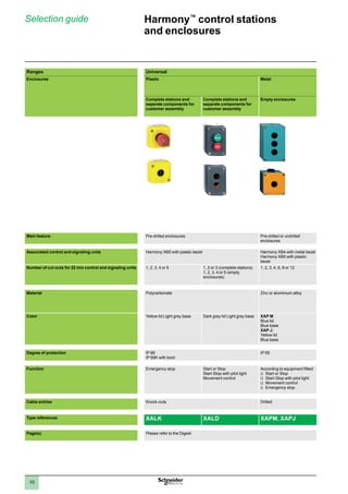
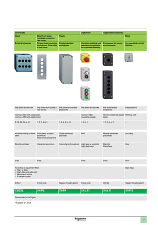
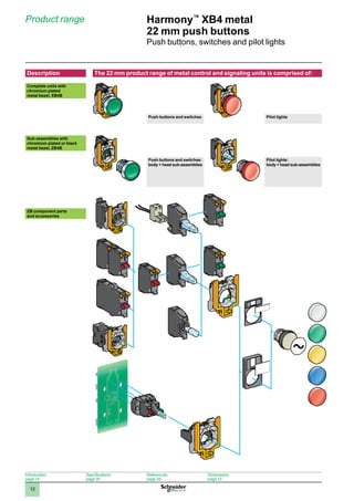
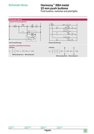
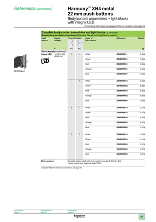
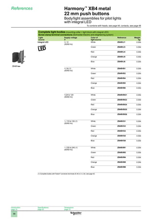
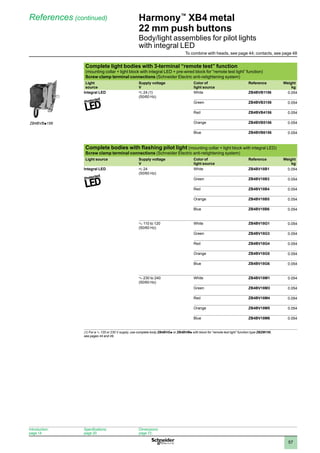
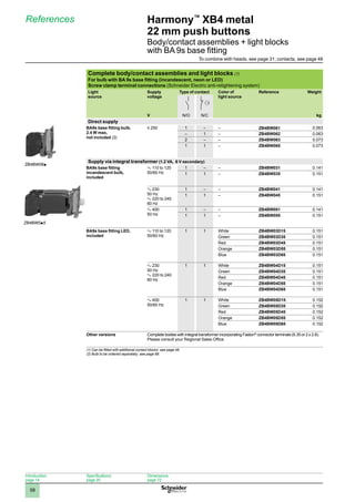
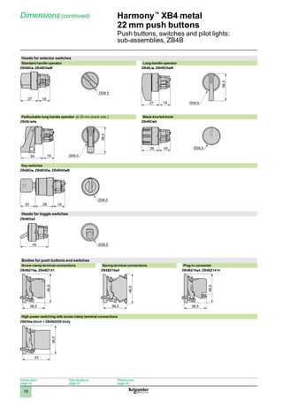
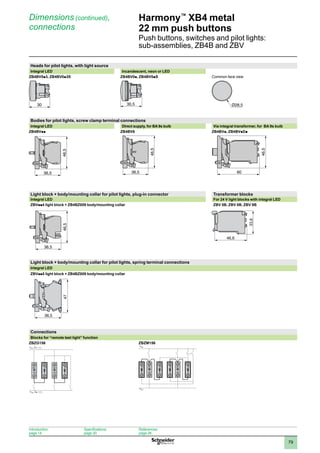
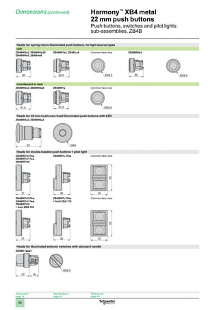
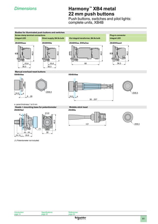
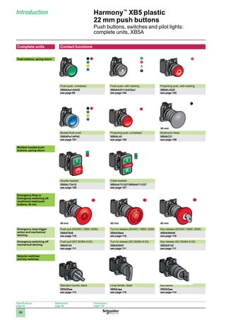
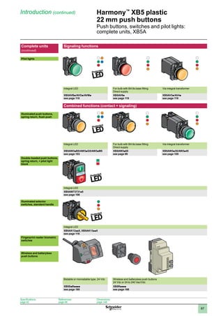
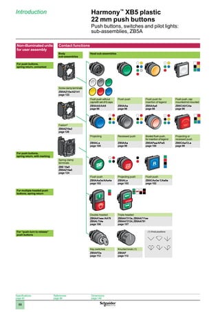
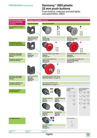
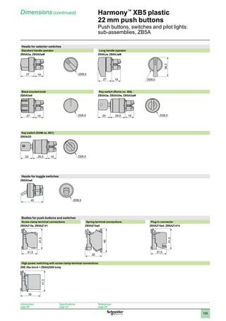
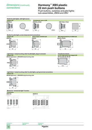
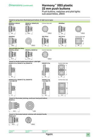
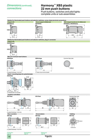
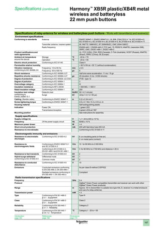
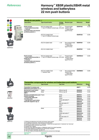
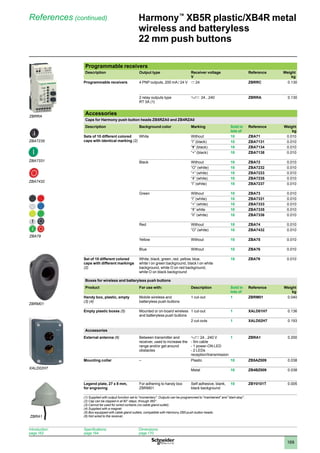
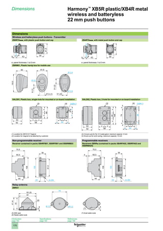
Catalog
2012
Harmony™
XB4/XB5/XB7
22mmpushbuttons
CÔNG TY CỔ PHẦN THIẾT BỊ ĐIỆN HOÀNG PHƯƠNG
ĐC: Số 10, ngõ 44, phố Võ Thị Sáu, P.Thanh Nhàn, Q.Hai Bà Trưng, TP. Hà Nội
MST: 0106798886
Tel: 024.3215.1322
Website: Hoangphuong.com.vn
Phone/Zalo: 0944.240.317 / 0975.123.698 / 0961.008.858
Email: Codienhoangphuong@gmail.com
1
2
3
4
5
6
7
8
9
10
2
1
2
3
4
5
6
7
8
9
10
3
Reliable components for any situation…
• Robust
• Conforms to the highest quality and safety standards
Innovative solutions for any application…
• Comprehensive, complimentary product line
Time-savings for added value…
• Simplicity and speed of installation
• Worldwide availability
Harmony also has a
comprehensive line of:
• Beacons and indicator banks
• Control stations
• Cam switches
• Joystick controllers
Harmony™
22 mm push buttons…
your all-around solution for all your 22 mm push button applications.
1
2
3
4
5
6
7
8
9
10
4
IP66
IP69K
High degree of protection
as standard (without boot)
Up to 3
functions
in a 22 mm cut-out
Save space…
Multiple head push buttons
For references see pages 32 & 106
For substitution table see page 180
Comprehensive product offer
• 
Double-headed, double-headed + pilot
light, triple-headed push button versions
• 3rd STOP function button or pilot light
Customization
• 
Using new tamperproof markings and
push button cap colors
Control machine access…
Biometric switch
Designed to restrict access to industrial
machines or processes to authorized
personnel only, for…
• starting, set-up, adjustment
• switching to maintenance mode
• re-setting following an emergency stop
Robust and reliable
• 
Reduces problems inherent in existing systems:
loss, theft or copying of keys, badges and passwords
• IP65, NEMA 12 degree of protection
• Protective cover (as accessory)
• Resistant to mechanical shock and vibration
• EMC protection
For references see page 160
New Harmony™
Machine Control Solutions…
Simple
• Mounted in the same
way as a standard 22 mm
switch
• Fully stand-alone product
with direct parametering
and registration/recording
on front face
200
recordable fingerprints
capacity
1
2
3
4
5
6
7
8
9
10
5
Boost performance and speed…
Contact blocks
Achieve
Conformity
Our mushroom head Emergency
stop push buttons conform to
applicable standards, helping you
to achieve conformity
to the Machinery
directive
66%
savings
in connection time vs. a
screw clamp connector
Conform to new standards…
“Emergency stop” function
The Emergency stop function is comprised of:
• 
Emergency stop function legend
with EN/IEC60417-5638 symbol
For references see pages 36  110
For references see pages 50  124
Quick and secure connection
Spring terminal connection
• Intuitive cabling without using tool
• 
Excellent resistance to mechanical shock
and vibration
• Trustworthy, safe and secure connections
exclusively from Schneider Electric
• 
Red, trigger action, latching head
that conforms to standards EN/ISO
13850 and EN/IEC 60947-5-5
1
2
3
4
5
6
7
8
9
10
6
Contents
New Harmony™
Machine Control Solutions . . . . . . . . . . . . . . . . . . . . . . . . . . . . . 4
Selection guide
Harmony™
XB4 metal and XB5/XB7 plastic 22 mm push buttons . . . . . . . . . . . . . . . . . . . . . . . 8
Harmony™
control stations and enclosures . . . . . . . . . . . . . . . . . . . . . . . . . . . . . . . . . . . . . . . . . . . 10
Harmony™
XB4 metal products
Product range  . . . . . . . . . . . . . . . . . . . . . . . . . . . . . . . . . . . . . . . . . . . . . . . . . . . . . . . . . . . . . . . . . . . . . . 12
Schematic library . . . . . . . . . . . . . . . . . . . . . . . . . . . . . . . . . . . . . . . . . . . . . . . . . . . . . . . . . . . . . . . . . . . 13
Introduction
Complete units . . . . . . . . . . . . . . . . . . . . . . . . . . . . . . . . . . . . . . . . . . . . . . . . . . . . . . . . . . . . . . . . . . . . . 14
Sub-assemblies  . . . . . . . . . . . . . . . . . . . . . . . . . . . . . . . . . . . . . . . . . . . . . . . . . . . . . . . . . . . . . . . . . . . 16
Specifications
Complete units and sub-assemblies . . . . . . . . . . . . . . . . . . . . . . . . . . . . . . . . . . . . . . . . . . . . . . . . . 20
Installation
Contact mounting . . . . . . . . . . . . . . . . . . . . . . . . . . . . . . . . . . . . . . . . . . . . . . . . . . . . . . . . . . . . . . . . . . 24
Contact sequence for selector switches . . . . . . . . . . . . . . . . . . . . . . . . . . . . . . . . . . . . . . . . . . . . . . 25
References
Push buttons, spring return
• Unmarked . . . . . . . . . . . . . . . . . . . . . . . . . . .  26 • Illuminated with integral LED . . . . . . . . . . . . .  29
• With marking . . . . . . . . . . . . . . . . . . . . . . . . .  28 • Illuminated with BA 9s base fitting . . . . . . . . .  31
Multiple head push buttons, spring return
• Double-headed push buttons . . . . . . . . . . . .  32 • Triple-headed push buttons  . . . . . . . . . . . . .  33
• + 1 white central pilot light block . . . . . . . . . .  32 • Accessories . . . . . . . . . . . . . . . . . . . . . . . . . .  33
Mushroom head push buttons
• Spring return . . . . . . . . . . . . . . . . . . . . . . . . .  34 • Latching . . . . . . . . . . . . . . . . . . . . . . . . . . . . . 35
• Illuminated, spring return . . . . . . . . . . . . . . . .  34 • Illuminated, latching . . . . . . . . . . . . . . . . . . . .  35
Emergency stop devices
• Trigger action and mechanical latching . . . . .  36
Emergency switching off devices
• Mechanical latching . . . . . . . . . . . . . . . . . . . .  37 • Illuminated, mechanical latching . . . . . . . . . .  37
Selector switches
• With standard handle  . . . . . . . . . . . . . . . . . .  38 • Key switches . . . . . . . . . . . . . . . . . . . . . . . . .  40
• With long handle . . . . . . . . . . . . . . . . . . . . . .  39 • With knurled knob . . . . . . . . . . . . . . . . . . . . .  41
• With long handle, padlockable  . . . . . . . . . . .  39 • Illuminated, w/ standard handle and integral LED . 42
Toggle switches . . . . . . . . . . . . . . . . . . . . . . . . . . . . . . . . . . . . . . . . . . . . . . . . . . . . . . . . . . . . . . . . . . . . 41
Pilot lights
• With integral LED . . . . . . . . . . . . . . . . . . . . . .  44 • With BA 9s base fitting  . . . . . . . . . . . . . . . . .  45
Specific functions
• Heads for manual overload reset push buttons 46 • Fuse carrier . . . . . . . . . . . . . . . . . . . . . . . . . .  46
• Heads + mounting base for potentiometer . .  46 • Joystick controllers . . . . . . . . . . . . . . . . . . . .  47
• Hour counters . . . . . . . . . . . . . . . . . . . . . . . .  46 • Wobble stick heads . . . . . . . . . . . . . . . . . . . .  47
• Annunciators . . . . . . . . . . . . . . . . . . . . . . . . .  46
Contact and illuminated functions (blocks  bodies)
• With screw clamp terminal connections . . . .  48 • With Faston®
connectors . . . . . . . . . . . . . . . .  52
• With spring clamp terminal connections . . . .  50 • For plug-in connector . . . . . . . . . . . . . . . . . .  53
• For printed circuit board  . . . . . . . . . . . . . . . .  51
Contact and illuminated functions (bodies)
• With integral LED . . . . . . . . . . . . . . . . . . . . . .  54 • With BA 9s base fitting  . . . . . . . . . . . . . . . . .  58
Contact and light blocks for specific applications
• Contact blocks  . . . . . . . . . . . . . . . . . . . . . . .  48 • Light blocks for “remote test” function  . . . . .  49
• Flashing light blocks . . . . . . . . . . . . . . . . . . .  49 • LED suppressors . . . . . . . . . . . . . . . . . . . . . .  49
Accessories
• For heads  . . . . . . . . . . . . . . . . . . . . . . . . . . .  60 • For push buttons . . . . . . . . . . . . . . . . . . . . . .  68
Legends, legend holders . . . . . . . . . . . . . . . . . . . . . . . . . . . . . . . . . . . . . . . . . . . . . . . . . . . . . . . . . . . . 62
Dimensions and mounting . . . . . . . . . . . . . . . . . . . . . . . . . . . . . . . . . . . . . . . . . . . . . . . . . . . . . . . . . . . 72
Harmony™
XB5 plastic products
Product range  . . . . . . . . . . . . . . . . . . . . . . . . . . . . . . . . . . . . . . . . . . . . . . . . . . . . . . . . . . . . . . . . . . . . . . 84
Schematic library . . . . . . . . . . . . . . . . . . . . . . . . . . . . . . . . . . . . . . . . . . . . . . . . . . . . . . . . . . . . . . . . . . . 85
Introduction
Complete units . . . . . . . . . . . . . . . . . . . . . . . . . . . . . . . . . . . . . . . . . . . . . . . . . . . . . . . . . . . . . . . . . . . . . 86
Sub-assemblies  . . . . . . . . . . . . . . . . . . . . . . . . . . . . . . . . . . . . . . . . . . . . . . . . . . . . . . . . . . . . . . . . . . . 88
Specifications
Complete units and sub-assemblies . . . . . . . . . . . . . . . . . . . . . . . . . . . . . . . . . . . . . . . . . . . . . . . . . 92
Installation
Contact mounting . . . . . . . . . . . . . . . . . . . . . . . . . . . . . . . . . . . . . . . . . . . . . . . . . . . . . . . . . . . . . . . . . . 96
Contact sequence for selector switches . . . . . . . . . . . . . . . . . . . . . . . . . . . . . . . . . . . . . . . . . . . . . . 97
1
2
3
4
5
6
7
8
9
10
7
References
Push buttons, spring return
• Unmarked . . . . . . . . . . . . . . . . . . . . . . . . . . .  98 • Illuminated with integral LED . . . . . . . . . . . .  103
• With marking . . . . . . . . . . . . . . . . . . . . . . . .  102 • Illuminated with BA 9s base fitting . . . . . . . .  105
Multiple head push buttons, spring return
• Double-headed push buttons . . . . . . . . . . .  106 • Triple-headed push buttons  . . . . . . . . . . . .  107
• + 1 white central pilot light block . . . . . . . . .  106 • Accessories . . . . . . . . . . . . . . . . . . . . . . . . .  107
Mushroom head push buttons
• Spring return . . . . . . . . . . . . . . . . . . . . . . . .  108 • Illuminated, latching . . . . . . . . . . . . . . . . . . .  109
• Latching . . . . . . . . . . . . . . . . . . . . . . . . . . . . 109
Emergency stop devices
• Trigger action and mechanical latching . . . . . 110 • Illuminated, trigger action and mechanical latching 110
Emergency switching off devices
• Mechanical latching . . . . . . . . . . . . . . . . . . . . 111 • Illuminated, mechanical latching . . . . . . . . . . 111
Push buttons
• Push-turn to release  . . . . . . . . . . . . . . . . . . . 112
Selector switches
• With standard handle  . . . . . . . . . . . . . . . . . . 113 • With knurled knob . . . . . . . . . . . . . . . . . . . . . 115
• With long handle . . . . . . . . . . . . . . . . . . . . . . 113 • Illuminated, w/ standard handle and integral LED116
• Key switches . . . . . . . . . . . . . . . . . . . . . . . . . 114
Toggle switches . . . . . . . . . . . . . . . . . . . . . . . . . . . . . . . . . . . . . . . . . . . . . . . . . . . . . . . . . . . . . . . . . . . 115
Pilot lights
• With integral LED . . . . . . . . . . . . . . . . . . . . . . 118 • With BA 9s base fitting  . . . . . . . . . . . . . . . . . 119
Specific functions
• Heads for manual overload reset push buttons 120 • Annunciators . . . . . . . . . . . . . . . . . . . . . . . .  120
• Heads + mounting base for potentiometer .  120 • Fuse carrier . . . . . . . . . . . . . . . . . . . . . . . . .  120
• Hour counters . . . . . . . . . . . . . . . . . . . . . . .  120 • Joystick controllers . . . . . . . . . . . . . . . . . . . . 121
Contact and illuminated functions (blocks  bodies)
• With screw clamp terminal connections . . .  122 • With Faston®
connectors . . . . . . . . . . . . . . .  126
• With spring clamp terminal connections . . . . 124 • For plug-in connector . . . . . . . . . . . . . . . . .  127
• For printed circuit board  . . . . . . . . . . . . . . .  125
Contact and illuminated functions (bodies)
• With integral LED . . . . . . . . . . . . . . . . . . . . .  128 • With BA 9s base fitting  . . . . . . . . . . . . . . . .  132
Contact and light blocks for specific applications
• Contact blocks  . . . . . . . . . . . . . . . . . . . . . .  122 • Light blocks for “remote test” function  . . . .  123
• Flashing light blocks . . . . . . . . . . . . . . . . . .  123 • LED suppressors . . . . . . . . . . . . . . . . . . . . .  123
Accessories
• For heads  . . . . . . . . . . . . . . . . . . . . . . . . . .  134 • For push buttons . . . . . . . . . . . . . . . . . . . . .  144
Legends, legend holders . . . . . . . . . . . . . . . . . . . . . . . . . . . . . . . . . . . . . . . . . . . . . . . . . . . . . . . . . . . 138
Dimensions and mounting . . . . . . . . . . . . . . . . . . . . . . . . . . . . . . . . . . . . . . . . . . . . . . . . . . . . . . . . . . 148
Biometric switches . . . . . . . . . . . . . . . . . . . . . . . . . . . . . . . . . . . . . . . . . . . . . . . . . . . . . . . . . . . . . . . . . 160
Harmony™
XB5R plastic and XB4R metal
wireless and batteryless products
Introduction . . . . . . . . . . . . . . . . . . . . . . . . . . . . . . . . . . . . . . . . . . . . . . . . . . . . . . . . . . . . . . . . . . . . . . . 162
Specifications  . . . . . . . . . . . . . . . . . . . . . . . . . . . . . . . . . . . . . . . . . . . . . . . . . . . . . . . . . . . . . . . . . . . . . 164
References
Ready-to-use packs . . . . . . . . . . . . . . . . . . . . . . . . . . . . . . . . . . . . . . . . . . . . . . . . . . . . . . . . . . . . . . . 168
Transmitter components . . . . . . . . . . . . . . . . . . . . . . . . . . . . . . . . . . . . . . . . . . . . . . . . . . . . . . . . . . . 168
Programmable receivers . . . . . . . . . . . . . . . . . . . . . . . . . . . . . . . . . . . . . . . . . . . . . . . . . . . . . . . . . . . 169
Accessories  . . . . . . . . . . . . . . . . . . . . . . . . . . . . . . . . . . . . . . . . . . . . . . . . . . . . . . . . . . . . . . . . . . . . . . 169
Dimensions and schemes . . . . . . . . . . . . . . . . . . . . . . . . . . . . . . . . . . . . . . . . . . . . . . . . . . . . . . . . . . 170
Harmony™
XB7 plastic products
Specifications
Monolithic push buttons, switches and pilot lights  . . . . . . . . . . . . . . . . . . . . . . . . . . . . . . . . . . . . 172
References
Push buttons, spring return
• Unmarked . . . . . . . . . . . . . . . . . . . . . . . . . . . 174 • With marking . . . . . . . . . . . . . . . . . . . . . . . . . 175
Pilot lights
• With integral LED . . . . . . . . . . . . . . . . . . . . . . 176 • With BA 9s base fitting  . . . . . . . . . . . . . . . . . 176
Push buttons, illuminated
• With integral LED . . . . . . . . . . . . . . . . . . . . . . 176 • With BA 9s base fitting  . . . . . . . . . . . . . . . .  177
Selector switches and key switches . . . . . . . . . . . . . . . . . . . . . . . . . . . . . . . . . . . . . . . . . . . . . . . . . 177
Emergency switching off mushroom head push buttons . . . . . . . . . . . . . . . . . . . . . . . . . . . . . . . 177
Legends, legend holders . . . . . . . . . . . . . . . . . . . . . . . . . . . . . . . . . . . . . . . . . . . . . . . . . . . . . . . . . . . 178
Accessories, bulbs . . . . . . . . . . . . . . . . . . . . . . . . . . . . . . . . . . . . . . . . . . . . . . . . . . . . . . . . . . . . . . . . 178
Dimensions and mounting . . . . . . . . . . . . . . . . . . . . . . . . . . . . . . . . . . . . . . . . . . . . . . . . . . . . . . . . . . 179
Multiple head spring return push buttons substitution table . . . 180
Product reference index . . . . . . . . . . . . . . . . . . . . . . . . . . . . . . . . . . . . . . . . . . . . . . . . . . . 182
1
2
3
4
5
6
7
8
9
10
8
Harmony™
XB4 metal and
XB5/XB7 plastic
22 mm push buttons
Applications Pilot lights Push buttons, selector switches and pilot lights
Description of the range LED pilot lights
b	 Push buttons
b	
Emergency Stop buttons
b	
Emergency switching off push buttons
b	
Selector switches and key switches
b	
Illuminated push buttons
b	
Pilot lights
b	
Features Products Monolithic, compact,
low consumption
Complete units or sub-assemblies (body + head) Monolithic
Bezel Double insulated Metal, chromium plated
or black
Double insulated
Shape of head Circular Circular, square
or rectangular
Circular Circular or square Circular
Drilling or cut-out for mounting 8 and 12 mm 16 mm 22 mm 22 and 25 mm
Degree of
protection
Conforming to
IEC60529
IP 40
IP 65 with seal
IP 65 IP 66
IP 69K for selectors switches, multiple-headed
push buttons, and booted push buttons
IP 54
Cabling Tags for
2.8 x 0.5 mm
connectors,
or threaded
connector
Faston®
connectors
Solder pins for printed
circuit boards
Spring clamp terminal connections
Screw clamp terminal connections
Faston connectors
Connector
With adaptor for printed circuit board
Screw clamp
terminal connections
Mounting Panel thickness 1 to 8 mm 1 to 6 mm
Type references XVLA XB6 XB4 XB5 XB7*
Pages Please refer to the Digest 26 to 47 98 to 121 174 to 178
*Available Q1 2012
Selection guide
1
2
3
4
5
6
7
8
9
10
9
Joystick controllers Push buttons, selector switches and pilot lights Cam switches
2 or 4 direction
b	
Stay put or spring return
b	
Push buttons
b	
Emergency Stop buttons
b	
Emergency switching off push buttons
b	
Selector switches and key switches
b	
Illuminated push buttons
b	
Pilot lights
b	
Switches
b	
Stepping switches
b	
Reversing and changeover switches
b	
Ammeter switches
b	
Voltmeter switches
b	
Reversing switches
b	
Star-delta and reversing star-delta switches
b	
Pole change switches
b	
Complete units or sub-assemblies (body + head
with lever)
Complete units or sub-assemblies
(body + head)
Complete units or sub-assemblies (body + front
panel + head)
Chromium plated metal Double
insulated, black
Chromium plated metal
or double insulated
Metal, chromium plated or black Double insulated
Circular Hexagonal Square
22 mm 30 mm 16 or 22 mm: series K10
22 mm and multimounting: series K2
4 holes, 48 or 68 centers:
series K30 to K150
IP 65 IP 66 IP 65 IP 65 IP65: series K10
IP 40, IP 65 with seal: series K2
IP 40: series K30 to K150
Screw and captive cable clamp connections Screw and captive cable clamp connections
1 to 6 mm 1 to 6 mm 0.5 to 6 mm
(depending on model)
XD4PA XD2GA XD5PA 9001K, 9001SK K10, K2, K30, K50, K63, K115, K150
47 Please refer to
the Digest
121 Please refer to the Digest Please refer to the Digest
1
2
3
4
5
6
7
8
9
10
10
Selection guide Harmony™
control stations
and enclosures
Ranges Universal
Enclosures Plastic Metal
Complete stations and
separate components for
customer assembly
Complete stations and
separate components for
customer assembly
Empty enclosures
Main feature Pre-drilled enclosures Pre-drilled or undrilled
enclosures
Associated control and signaling units Harmony XB5 with plastic bezel Harmony XB4 with metal bezel
Harmony XB5 with plastic
bezel
Number of cut-outs for 22 mm control and signaling units 1, 2, 3, 4 or 5 1, 2 or 3 (complete stations)
1, 2, 3, 4 or 5 (empty
enclosures)
1, 2, 3, 4, 6, 8 or 12
Material Polycarbonate Zinc or aluminium alloy
Color Yellow lid Light grey base Dark grey lid Light grey base XAP M:
Blue lid
Blue base
XAP J:
Yellow lid
Blue base
Degree of protection IP 66
IP 69K with boot
IP 65
Function Emergency stop Start or Stop
Start-Stop with pilot light
Movement control
According to equipment fitted:
Start or Stop
v
v
Start-Stop with pilot light
v
v
Movement control
v
v
Emergency stop
v
v
Cable entries Knock-outs Drilled
Type references XALK XALD XAPM, XAPJ
Page(s) Please refer to the Digest
1
2
3
4
5
6
7
8
9
10
11
Universal Optimum Application specific
Metal Metal front plate,
insulated protective
rear cover
Plastic Metal
Empty enclosures Empty, flush mounting
enclosures: front plate
+ rear cover
Empty insulated
enclosures
Complete stations and
separate components
for customer assembly
Enclosures for severe
environments
Key operated control
stations
Pre-drilled enclosures Pre-drilled front plates 
rear covers
Pre-drilled or undrilled
enclosures
Pre-drilled enclosures Pre-drilled empty
enclosures
Fitted stations
Harmony XB4 with metal bezel
Harmony XB5 with plastic bezel
Harmony XB7,
monolithic, plastic
Harmony XB5 with plastic
bezel
With key lock
8, 16, 24, 30 or 40 1, 2, 3, 4 or 5 1, 2, 4, 8 or 16 1, 2 or 3 1, 2, 3, 4 or 5 –
Aluminium alloy or sheet
steel
Front plate: brushed
aluminium
Rear cover:polystyrene
Glass-reinforced
polyester
ABS Mineral reinforced
polyamide
Zinc alloy
Blue lid and base Unpainted aluminium Colored grey throughout Light grey or yellow lid
Light grey base
Black lid
Black base
Grey
IP 54 IP 65 IP 54 IP 66 IP 54
According to equipment fitted:
Start or Stop
v
v
Start-Stop with pilot light
v
v
Movement control
v
v
Emergency stop
v
v
Start-Stop
Drilled Knock-outs Tapped for cable gland Knock-outs ISO 20 Tapped for cable gland
XB2SL XAPE XAPA XAL E* XAL G XAP S
Please refer to the Digest
*Available Q1 2012
1
2
3
4
5
6
7
8
9
10
12
Harmony™
XB4 metal
22 mm push buttons
Push buttons, switches and pilot lights
Product range
Description The 22 mm product range of metal control and signaling units is comprised of:
Complete units with
chromium plated
metal bezel, XB4B
Push buttons and switches Pilot lights
Sub-assemblies with
chromium plated or black
metal bezel, ZB4B
Push buttons and switches:
body + head sub-assemblies
Pilot lights:
body + head sub-assemblies
ZB component parts
and accessories
Introduction:
page 14
Specifications:
page 20
References:
page 26
Dimensions:
page 72
1
2
3
4
5
6
7
8
9
10
13
Harmony™
XB4 metal
22 mm push buttons
Push buttons, switches and pilot lights
Schematic library
Schematic library
Typical wiring diagrams
R
M
M O.L.
L2
3
2
1
L1
STOP
START
L2
C
Test
L1
M
STOP
LSI
M3
(TEST) C
(TEST) C L2
L2
L1
(SIG)
CR
M2
M1
L2
(TEST) C
START
TEST
BUTTON
L1 L2
L1
(SIG)
L1
(SIG)
Push-To-Test Pilot Light Remote Test Pilot Light
Joystick controller functions
B
A 0 B
A 0
2 direction
Without spring return With spring return
B
A
D
C
0 B
A
D
C
0 B
A
D
C
0
4 direction
Without spring return With spring return
Introduction:
page 14
Specifications:
page 20
References:
page 26
Dimensions:
page 72
1
2
3
4
5
6
7
8
9
10
14
Complete units Contact functions
Push buttons, spring return,
with chromium plated metal
bezel
Flush push, unmarked Flush push, with marking Projecting push, with marking
XB4BAp1/BA42
see page 26
XB4BA3311
see page 28
XB4BL4322
see page 28
Booted flush push Projecting push, unmarked Mushroom head
XB4BPp1/BP42
see page 27
XB4BL42
see page 27
XB4BC21
see page 34
Multiple-headed push
buttons, spring return, with
chromium plated metal bezel
Double-headed Triple-headed
XB4BL73415
see page 33
XB4BA731327/XB4BA711237
see page 33
Emergency Stop or
Emergency switching off
mushroom head push
buttons, 40 mm, with
chromium plated metal bezel
Emergency stop trigger
action and mechanical
latching
Push-pull (EN/ISO 13850: 2006) Turn to release (EN/ISO 13850: 2006) Key release (EN/ISO 13850: 2006)
XB4BT845
see page 36
XB4BS844p
see page 36
XB4BS9445
see page 36
Emergency switching off
mechanical latching
Push-pull (IEC 60364-5-53) Turn to release (IEC 60364-5-53) Key release (IEC 60364-5-53)
XB4BT42
see page 37
XB4BS542
see page 37
XB4BS142
see page 37
Selector switches and key
switches, with chromium
plated metal bezel
Standard handle, black Long handle, black Key switch
XB4BDpp
see page 38
XB4BJpp
see page 39
XB4BGpp
see page 40
Harmony™
XB4 metal
22 mm push buttons
Push buttons, switches and pilot lights:
complete units, XB4B
Introduction
40 mm
Specifications:
page 20
References:
page 26
Dimensions:
page 72
40 mm 40 mm 40 mm
1
2
3
4
5
6
7
8
9
10
15
Harmony™
XB4 metal
22 mm push buttons
Push buttons, switches and pilot lights:
complete units, XB4B
Introduction (continued)
Complete units Signaling functions
Pilot lights
Integral LED For bulb with BA 9s base fitting
Direct supply
Via integral transformer with secondary
XB4BVBp/BVGp/BVMp
see page 44
XB4BV6p
see page 45
XB4BV3p/BV4p
see page 45
Combined functions (contact + signaling)
Illuminated push buttons,
spring return, flush push,
chromium plated metal bezel
Integral LED For bulb with BA 9s base fitting
Direct supply
Via integral transformer
XB4BW3pB5/BW3pG5/BW3pM5
see page 29
XB4BW3p65
see page 31
XB4BW3p35/BW3p45
see page 31
Double-headed push buttons
+ pilot light block, spring
return, chromium plated
metal bezel
Integral LED
XB4BW73731p5
see page 32
Illuminated selector switches
with standard handle,
chromium plated metal bezel
Integral LED
XB4BK12pp5, XB4BK13pp5
see page 42
Wireless and batteryless
push button
Ready-to-use packs
XB4Rpppp
see page 168
Specifications:
page 20
References:
page 26
Dimensions:
page 72
1
2
3
4
5
6
7
8
9
10
16
Harmony™
XB4 metal
22 mm push buttons
Push buttons, switches and pilot lights:
sub-assemblies, ZB4B
Non-illuminated units
for user assembly
Contact functions
Body
sub-assemblies
Head sub-assemblies, chromium plated or black metal bezel
For push buttons,
spring return, unmarked
Screw clamp
terminals
ZB4BZ10p/BZ141
page 48
Flush push
without cap
Flush push
with set of 6 caps
Flush push Flush push for
insertion of legend
ZB4BA0
page 26
ZB4BA9
page 26
ZB4BAp
page 26
ZB4BAp8
page 26
Faston®
ZB4BZ10p3
page 52
Projecting push Recessed push Booted flush/
projecting push
Booted flush push
for insertion of legend
ZB4BLp
page 26
ZB4BAp6
page 27
ZB4BPp/ BPpS
page 27
ZB4BPp8
page 27
For push buttons,
spring return, with marking
Spring clamp
terminals
ZBE 10p5
ZB4BZ10p5
page 50
Flush push Projecting push
ZB4BAp3p/BAp4p
ZB4BA334/335
page 28
ZB4BLp3p
page 28
For multiple-headed push
buttons, spring return
Double-headed push
buttons
Triple-headed push buttons
ZB4BA7ppp
ZB4BA79
ZB4BL734p
page 32
ZB4BA7313p
ZB4BA711pp
ZB4BA72124
ZB4BA791
page 33
Introduction
Specifications:
page 20
References:
page 26
Dimensions:
page 72
1
2
3
4
5
6
7
8
9
10
17
Harmony™
XB4 metal
22 mm push buttons
Push buttons, switches and pilot lights:
sub-assemblies, ZB4B
Non-illuminated units
for user assembly
(continued)
Contact functions
Body
sub-assemblies
Head sub-assemblies, chromium plated or black metal bezel
For mushroom head push
buttons
Screwclampterminals Spring return Latching
ZB4BZ10p/BZ141
page 48
ZB4BCp/BRp
see page 34
ZB4Bp2/BSp2/BS55
see page 35
For Emergency Stop or
Emergency switching off
mushroom head push buttons
Emergency stop trigger
action and mechanical
latching
Faston®
Push-pull (EN/ISO 13850: 2006) Turn to release (EN/ISO 13850: 2006)
ZB4BZ10p3
page 52
ZB4BT84
see page 36
ZB4BS8p4
see page 36
Emergency switching off
mechanical latching
Push-pull (IEC 60364-5-3) Turn to release (IEC 60364-5-3)
ZB4BT4/BX4
see page 37
ZB4BS44/BS54/BS64
see page 37
Emergency stop trigger
action and mechanical
latching
Springclampterminals Key release (EN/ISO 13850: 2006)
ZBE 10p5
ZB4BZ10p5
page 50
ZB4BS9p4
see page 36
Emergency switching off
mechanical latching
Key release (IEC 60364-5-3)
ZB4BS74/BS14/BS24
see page 37
(1) Switch handle
and knob positions
(2) Key switch
positions
Key withdrawal positions
For selector switches
and key switches
Standard black
handle (1)
Long black handle
(1)
ZB4BDp
page 38
ZB4BJp
page 39
Knurled black knob
(1)
Key switch (2)
ZB4BDp9
page 41
ZB4BGpp/
BGpTEC10
page 40
For toggle switches (3) Lever positions
2-position lever (3)
ZB4BDp8, see page 41
Ø 30
Ø 40
Ø 60
Ø 30
Ø 40
Ø 60
Ø 30
Ø 40
Ø 60
Ø 30
Ø 40
Ø 60
Ø 30
Ø 40
Ø 60
Introduction (continued)
Specifications:
page 20
References:
page 26
Dimensions:
page 72
1
2
3
4
5
6
7
8
9
10
18
Harmony™
XB4 metal
22 mm push buttons
Push buttons, switches and pilot lights:
sub-assemblies, ZB4B
Pilot lights
for user assembly
Signaling functions
Body sub-assemblies
with integral LED
Head sub-assemblies
With lens fitted
ZB4BV0p3
see page 44
Connection: screw
clamp terminals
ZB4BVJ/BVB/BVG/
BVM
see page 56
Connection: plug-in
connector
With 5 separate lenses, not fitted
ZB4BVBp4/BVGp4/
BVMp4
ZB4BV003
see page 44
please consult your
Regional Sales Office
Body sub-assemblies
for BA 9s bulb
Head sub-assemblies
With lens fitted
ZB4BV0p, ZB4BV0pS
see page 45
Direct supply
Connection: screw
clamp terminals
ZB4BV6
see page 59
Via integral transformer
Connection:screwclamp
terminals
ZB4BVpDp
see page 59
Introduction (continued)
Specifications:
page 20
References:
page 26
Dimensions:
page 72
1
2
3
4
5
6
7
8
9
10
19
Illuminated push
buttons
for user assembly
Combined functions (contact + signaling)
Body sub-assemblies
with integral LED
Head sub-assemblies, chromium plated or black metal bezel
For illuminated push
buttons,
spring return
Flush push Flush push with
illuminated ring
Flush push for insertion of legend
Screw clamp terminals ZB4BW3p3
page 30
ZB4BW9p3
page 30
ZB4BAp8
page 30
ZB4BW0B/BW0G/
BW0M
page 54
Booted flush push Projecting push Mushroom head, spring return
ZB4BW5p3
page 30
ZB4BW1p3,
ZB4BW1p3S
page 30
ZB4BW4p3
page 34
For illuminated double-
headed push buttons,
spring return
Plug-in connector
ZB4BW0Bpp4
please consult your
Regional Sales Office
Double-headed (flush/flush push) + central pilot light
Double-headed (flush/projecting push) + central pilot light
ZB4BW7A17pp / ZB4BW7A374p / ZB4BW7A9, see page 32
ZB4BW7L374p, see page 32
For illuminated
“push-push to release”
push buttons and
illuminated selector
switches with standard
handle Spring clamp terminals Selector switches with standard handle
ZBVppp
page 50
ZB4BK1pp3
see page 42
For illuminated
mushroom head push
buttons
Mushroom head, latching Emergency switching off,
mechanical latching, push-pull
ZB4BW6p3
see page 35
ZB4BW643
see page 37
Body sub-assemblies
for BA 9s bulb
Head sub-assemblies, chromium plated or black metal bezel
For illuminated push
buttons,
spring return
Flush push Projecting push
Direct supply or via
integral transformer
Screw clamp terminals
ZB4BW3p,
ZB4BW3pS
page 31
ZB4BW1p,
ZB4BW1pS
page 31
ZB4BW0ppp
page 58
Harmony™
XB4 metal
22 mm push buttons
Push buttons, switches and pilot lights:
sub-assemblies, ZB4B
Introduction (continued)
Specifications:
page 20
References:
page 26
Dimensions:
page 72
1
2
3
4
5
6
7
8
9
10
20
Harmony™
XB4 metal
22 mm push buttons
Push buttons, switches and pilot lights
Specifications
Environment
Protective treatment
standard version
“TH” treatment
Ambient air temperature
around the device
Storage °C - 40 to + 70
Operation °C - 25 to + 70: LED and neon bulb versions
- 25 to + 55: incandescent bulb version
Electric shock protection Conforming to IEC 61140 Class I
Degree of protection Conforming to IEC 60529 IP 66
IP 69 K (Selector switches and multiple-headed
push buttons)
Conforming to NEMA NEMA type 4X and 13, unless otherwise stated
Resistance to high pressure washer Pa 70 x 105
(70 bar); distance: 0.1 m
Temperature: 55°C
Mechanical shock protection Conforming to IEC 50102 Non-illuminated heads: IK 03
Illuminated heads: IK 05
Selector switch heads: IK 06
Conforming to standards EN/IEC 60947-1, EN/IEC 60947-5-1,
EN/IEC 60947-5-4, EN/IEC 60947-5-5,
EN/IEC60204-1 and EN/ISO 13850:2006
(Emergency stop trigger action and mechanical
latching push buttons, see page 36063/2),
IEC60364-5-53 (Emergency switching off
mechanical latching push buttons,
see page 36063/3)
JIS C4520, UL 508, CSA C22-2 no. 14
Product certifications UL Listed, CSA Standard single contacts with screw clamp and
spring terminals: A600; Q600
Double contacts with screw clamp terminals:
A600; Q600
Light blocks with screw clamp terminals
Joystick controllers XD4PA/ZD4PA: A600; R300
Special contact blocks:
ZBE201: A300; Q300
v	
ZBE202: A600; Q600
v	
Single contacts for high power switching:
ZBE501 and ZBE 502: A300; P300
v	
UL Recognized, CSA Standard single contacts for plug-in connector:
A300; R300
Standard contacts for printed circuit board:
B300; R300
BV, RINA, LROS, DNV, GL Standard single contacts and double contacts with
screw clamp or spring terminals:
Terminal referencing Conforming to EN 50005
and EN 50013
Specifications of contact or combined contact and signaling functions (see page 24)
Mechanical specifications
Contact operation N/C or N/O Slow break
Positive operation Conforming to
EN/IEC 60947-5-1 appendix K
All functions incorporating a N/C contact have
positive opening operation
Operating travel
(to change the electrical state)
Push button mm Changing N/C state: 1.5
Changing N/O state: 2.6
Total travel: 4.3
Operating force Push button N Changing N/C state: 3.5
Changing N/O state: 3.8
Additional contact only
(extra to change state)
N Single N/C contact: 2
Single N/O contact: 2.3
N Double N/C contact: 3.4
Double N/O contact: 5
Double contact N/C + N/O: 4.6
Emergency stop or Emergency
switching off with N/C + N/O
N Standard push-pull: 45
Trigger action push-pull: 50
N Standard turn to release and key release: 40
Trigger action turn to release and key release,
“trigger action”: 44
Introduction:
page 14
References:
page 26
Dimensions:
page 72
1
2
3
4
5
6
7
8
9
10
21
Harmony™
XB4 metal
22 mm push buttons
Push buttons, switches and pilot lights
Specifications (continued)
Specifications of contact or combined contact and signaling functions (continued) (see page 24)
Mechanical specifications (continued)
Operating torque
(to change the electrical state)
Selector switches N.m N/O contact: 0.14
Additional contact only N.m N/O contact: 0.05
Mechanical durability
(in millions of operating cycles)
Push button Spring return 5
Multiple-headed 1
Push-push
to release
0.5
Selector switch Non-illuminated 1
Illuminated 0.5
Toggle switch 0.5
Emergency Stop or
Emergency switching off push button
0.3 with 3 contacts
Joystick controller 1
Standard contact block only 5
Low power switching contact
block only (dust protected)
0.5
Vibration resistance Conforming to IEC 60068-2-6 Frequency: 2 to 500 Hz: 5 gn
Mechanical shock resistance Conforming to IEC 60068-2-27 All functions except mushroom head push buttons,
spring return:
half sine wave acceleration 11 ms: 50 gn
v	
half sine wave acceleration 18 ms: 30 gn
v	
Mushroom head push button, spring return:
half sine wave acceleration 11 ms: 10 gn
v	
Electrical specifications
Cabling capacity Conforming to EN/IEC 60947-1 mm2
Standard block with screw clamp or spring terminals:
Min: 1 x 0.22 without cable end
Max: 2 x 1.5 with cable end
Cross headed screws (Pozidriv or Philips type 1),
slotted for flat 4 and 5.5 mm screwdriver
Tightening torque: 0.8 N.m (maxi 1.2 N.m)
Contact blocks for high power switching:
Min: 1 x 0.5 without cable end
Max: 2 x 2.5 with or without cable end
Contact material Silver alloy (Ag / Ni) Standard single and double blocks with screw
clamp or spring terminals
Blocks for plug-in connector
Standard blocks for printed circuit board
connection
Gold flashed (Ag / Ni / Au) Low power switching contact blocks with screw
clamp terminals
Low power switching contact blocks for printed
circuit board connection
Short-circuit protection Conforming to EN/IEC 60947-5-1d A Standard single and double blocks with screw
clamp or spring terminals: 10
(gG cartridge fuse conforming to IEC 60269-1)
Blocks for plug-in connector: 4
(gG cartridge fuse conforming to IEC 60269-1)
Standard blocks for printed circuit board
connection: 4
(gG cartridge fuse conforming to IEC 60269-1)
Rated thermal current Conforming to EN/IEC 60947-5-1 A Standard single and double blocks with screw
clamp or spring terminals: 10
Blocks for plug-in connector: 10
Standard blocks for printed circuit board
connection: 6
Rated insulation voltage Conforming to EN/IEC 60947-1 V Standard single and double blocks with screw
clamp or spring terminals: Ui = 600, degree of
pollution 3
Blocks for plug-in connector or Faston®
connectors:
Standard blocks for printed circuit board connection
Contact blocks for high-power switching:
Ui = 250, degree of pollution 3
Rated impulse withstand voltage Conforming to /IEC 60947-1 kV Standard single and double blocks with screw
clamp or spring terminals: Uimp = 6
Blocks for plug-in connector
Standard blocks for printed circuit board
connection
Contact blocks for high-power switching
applications: Uimp = 4
Introduction:
page 14
References:
page 26
Dimensions:
page 72
1
2
3
4
5
6
7
8
9
10
22
Harmony™
XB4 metal
22 mm push buttons
Push buttons, switches and pilot lights
Specifications (continued)
Specifications of contact or combined contact and signaling functions (continued) (see page 24)
Electrical specifications (continued)
Rated operational specifications
Conforming to EN/IEC 60947-5-1
a.c. supply:
utilization category AC-15
Standard single and double blocks with screw
clamp or spring terminals:
A600: Ue = 600 V and le = 1.2 A or
Ue = 240 V and Ie = 3 A or
Ue = 120 V and le = 6 A
Blocks for plug-in connector:
A300: Ue = 120 V and le = 6 A or
Ue = 240 V and le = 3 A
Standard blocks for printed circuit board connection:
B300: Ue = 120 V and le = 3 A or
Ue = 240 V and le = 1.5 A
Special contact blocks:
ZBE201: A300: Ue = 240 V and le = 3 A or
v	
Ue = 120 V and le = 6 A (with insulation
voltage Ui = 500 V)
ZBE202: A600: Ue = 600 V and le = 1.2 A or
v	
Ue = 240 V and le = 3Aor Ue = 120 V and le = 6A
Contact blocks for high power switching:
ZBE50
v	 p: A300: Ue = 240 V and le = 3 A or
Ue = 120 V and le = 6 A
d.c.supply:
utilization category DC-13
Standard single and double blocks with screw
clamp or spring terminals
Q600: Ue = 600 V and le = 0.1 A or
Ue = 250 V and le = 0.27 A or
Ue = 125 V and le = 0.55 A
Joystick controllers XD4PA/ZD4PA:
R300: Ue = 125 V and le = 0.22 A or
Ue = 250 V and le = 0.1 A
Blocks for plug-in connector:
R300: Ue = 125 V and le = 0.22 A or
Ue = 250 V and le = 0.1 A
Standard blocks for printed circuit board connection:
R300: Ue = 125 V and le = 0.22 A or
Ue = 250 V and le = 0.1 A
Special contact blocks:
ZBE201: Q300; Ue = 125 V and le = 0.55 A or
v	
Ue = 250 V and le = 0.27 A
ZBE202: Q600; Ue = 600 V and le = 0.1 A or
v	
Ue = 250 V and le = 0.27 A or
Ue = 125 V and le = 0.55 A
Contact block for high power switching:
ZBE50
v	 p: P300: Ue = 125 V and le = 1.1 A or
Ue = 250 V and le = 0.55 A
Specifications of
special contact blocks
Low power switching VA
A
V
P max: 12
I max: 0.1
U max: 24
High power switching
Conforming to
IEC/EN 60947-5-1
100 000 operating cycles
Load factor: 0.5
Operating rate: 900 cycles/hour
VA
A
V
P max: 240
I max: 10
U: 24 c
Electrical durability
Conforming to EN/IEC 60947-5-1 appendix C
Operating rate 3600 operating cycles/hour
Load factor: 0.5
a.c. supply for 1 million
operating cycles
utilization category AC-15
Standard single blocks with screw clamp or spring
terminals:
V
A
24
4
120
3
230
2
Standard double blocks with screw clamp
terminals and blocks for plug-in connector:
V
A
24
3
120
1.5
230
1
d.c. supply for 1 million
operating cycles
utilization category DC-13
Standard single blocks with screw clamp or spring
terminals:
V
A
24
0.5
110
0.2
Standard double blocks with screw clamp
terminals and blocks four plug-in connector:
V
A
24
0.4
110
0.15
Electrical reliability
Failure rate
Conforming to EN/IEC 60947-5-4
In clean environment Standard blocks:
at 17 V and 5 mA,
-	 l  10-8
at 5 V and 1 mA,
-	 l  10-6
Special blocks with gold flashed contacts for low
power switching:
at 5 V and 1 mA,
-	 l  10-7
In dusty environment Special blocks with gold flashed contacts and dust
protection for low power switching only:
at 5 V and 1 mA,
-	 l  10-7
Introduction:
page 14
References:
page 26
Dimensions:
page 72
1
2
3
4
5
6
7
8
9
10
23
Harmony™
XB4 metal
22 mm push buttons
Push buttons, switches and pilot lights
Specifications (continued)
Specifications of illuminated units (pilot lights)
Mechanical specifications
Vibration resistance Conforming to IEC 60068-2-6 Frequency: 12 to 500 Hz: 5 gn
Electric shock resistance Conforming to IEC 60068-2-27 Half sine wave acceleration 11 ms: 50 gn
Half sine wave acceleration 18 ms: 30 gn
Electrical specifications
Cabling capacity Conforming to EN/IEC 60947-1 mm2
Screw clamp and spring terminals
Min: 1 x 0.22 without cable end
(1 x 0.34 for linking)
Max: 2 x 1.5 with cable end
Rated insulation voltage Conforming to EN/IEC 60947-1 V Direct supply pilot light blocks (BA 9s bulb):
Ui = 250, degree of pollution 3
Pilot light blocks with integral LED:
Ui = 250, degree of pollution 3
Pilot light blocks with transformer:
Ui = 600, degree of pollution 3
Rated impulse withstand voltage Conforming to EN/IEC 60947-1 kV Direct supply pilot light blocks (BA 9s bulb):
Uimp = 4
Pilot light blocks with integral LED: Uimp = 4
Pilot light blocks with transformer: Uimp = 6
Specific specifications of single light blocks with integral LED
Voltage limits For rated voltage V 12 V: 10 to 15 c; 10.2 to13.8 a
24 V: 19.2 to 30 c; 21.6 to 26.4 a
24 to 120 V: 19.2 to 132 c; 21.6 to 132 a
48 to 120 V: 40 to 132 a
230/240 V: 195 to 264 a
Current consumption Applicable to all colors mA Blocks with z 12 V supply: 18
Blocks with z 24 V supply: 18
Blocks with a 120 V supply: 14
Blocks with a 240 V supply: 14
Service life At rated voltage and at an
ambient temperature of 25 °C
H 100 000
Surge withstand Conforming to IEC 61000-4-5 kV 1
Resistance to fast transients Conforming to IEC 61000-4-4 kV 2
Resistance to electromagnetic fields Conforming to IEC 61000-4-3 V/m 10
Resistance to electrostatic discharges Conforming to IEC 61000-2-6 kV 8: in free air, in insulating parts
6: on contact, on metal parts
Direct parallel connection across inductive load
e.g.: contactor coil or solenoid
Maximum power of load VA For high power applications (u 30 VA), a ZBZVp
LED suppressor must be connected across the
light block terminals (see page 49)
Electromagnetic emission Conforming to IEC 55011 Class B
Specific specifications
Body/mounting collar
Tightening torque of mounting screw N.m 0.8 (max 1.2)
Hour counters and annunciators
Voltage limits Hour counter and annunciator ± 10% of the nominal voltage
Current consumption Hour counter mA XB5DSB: 7 to 15
XB5DSG: 8
XB5DSM: 8
Annunciator mA 5
Introduction:
page 14
References:
page 26
Dimensions:
page 72
1
2
3
4
5
6
7
8
9
10
24
Harmony™
XB4 metal
22 mm push buttons
Contact mounting - Contact sequence
Maximum recommended configurations for achieving catalog specifications
Unit type
(complete units XB4B, heads ZB4B)
Push buttons, spring return
XB4BAp, ZB4BAp,
(except ZB4BAp8)
XB4BCp, ZB4BCp,
XB4BLp, ZB4BLp,
XB4BPp, ZB4BPp,
ZB4BRp
Triple-headed push buttons
XB4BA731327,
XB4BA711137,
ZB4BA7313p, ZB4BA7111p,
ZB4BA72124, ZB4BA791
Double-headed push
buttons
XB4BL73415, ZB4BA712p,
ZB4Bp734p, ZB4BA79
Illuminated push buttons,
spring return XB4BWp,
ZB4BWp, ZB4BAp8
Double-headed push buttons
+ pilot light block
XB4BW73731p5,
ZB4BW7A17pp,
ZB4BW7p374p, ZB4BW7A9
Solution using single contacts
Solution using single and double contacts
Maximum recommended
configurations
Single contacts 9 6 6
Double contacts
+
single contacts
3
+
3
2
+
2
2
+
2
Light block – – 1
Possible configurations for high power switching contacts (1) (2)
High power switching contact blocks with screw clamp terminal connections:
ZBE 501, ZBE 502, ZBE 503, ZBE 504 and ZBE 505
High power switching contact blocks with connection by Faston®
connectors
ZBE 5013, ZBE 5023, ZBE 5033, ZBE 5043 and ZBE 5053
1 N/O 1 N/C 1 N/O + N/C
1 N/O + N/O
1 N/C + N/C
(1) The configurations are not upgradable and cannot be combined with other types of contact
and signaling functions.
(2) High power switching contacts are not compatible with Harmony triple-headed push buttons.
Single contact Double contact
Light block Possible location
Installation
Introduction:
page 14
Specifications:
page 20
References:
page 26
Dimensions:
page 72
1
2
3
4
5
6
7
8
9
10
25
Emergency stop
or Emergency switching off
XB4BTp, ZB4BTp,
XB4BSp, ZB4BSp
Selector switches
Standard handle XB4BD
b	 p, ZB4BDp,
Long handle XB4BJ
b	 p, ZB4BJp,
Knurled knob ZB4BD
b	 p9,
Key switch XB4BG
b	 p, ZB4BGp
Illuminated selector switches,
standard handle
XB4BKp, ZB4BKp
Toggle switches
ZB4BDp8
4 4 5 4 6 4 6
2
+
0
1
+
2
2
+
1
1
+
2
2
+
2
2
+
0
3
+
0
– – – – – 1 –
Introduction:
page 14
Specifications:
page 20
References:
page 26
Dimensions:
page 72
Sequence of contacts fitted to selector switch bodies
Unit type Selector switches
2-position 3-position
Push Position Top
Bottom
Location L C R L C R L C R L C R L C R
State 0 0 0 1 1 1 1 1 0 0 0 0 0 1 1
Contacts N/O v v v b b b b b v v v v v b b
N/C b b b v v v v v b b b b b v v
L left, C center, R right
v open, b closed
315° 45° 315° 0° 45°
1
2
3
4
5
6
7
8
9
10
26
Harmony™
XB4 metal
22 mm push buttons
Spring return push buttons, unmarked
Assembly of other products using body/contact assemblies, see page 48; accessories, see pages 60 and 62
References
Push buttons with flush push (1)
Screw clamp terminal connections (Schneider Electric anti-retightening system)
Shape
of head
Type
of push
Type of contact Color
of push
Reference Weight
kg
N/O N/C
Complete units
Flush 1 – White XB4BA11
(ZB4BZ101 + ZB4BA1)
0.080
Black XB4BA21
(ZB4BZ101 + ZB4BA2)
0.080
Green XB4BA31
(ZB4BZ101 + ZB4BA3)
0.080
Yellow XB4BA51
(ZB4BZ101 + ZB4BA5)
0.080
Blue XB4BA61
(ZB4BZ101 + ZB4BA6)
0.080
– 1 Red XB4BA42
(ZB4BZ102 + ZB4BA4)
0.080
Heads only
Without cap (2) – ZB4BA0 0.028
Flush, with set of 6 colored caps 6 colors (3) ZB4BA9 0.038
Flush White ZB4BA1 0.029
Black ZB4BA2 0.029
Green ZB4BA3 0.029
Red ZB4BA4 0.029
Yellow ZB4BA5 0.029
Blue ZB4BA6 0.029
Grey ZB4BA8 0.029
Flush with transparent cap
for insertion of legend (4)
White ZB4BA18 0.028
Green ZB4BA38 0.028
Red ZB4BA48 0.028
Yellow ZB4BA58 0.028
Blue ZB4BA68 0.028
Flush (high bezel) White ZB4BA14 0.034
Black ZB4BA24 0.034
Green ZB4BA34 0.034
Red ZB4BA44 0.034
Yellow ZB4BA54 0.034
Blue ZB4BA64 0.034
Push buttons with projecting push (1)
Screw clamp terminal connections (Schneider Electric anti-retightening system)
Shape
of head
Type
of push
Type of contact Color
of push
Reference Weight
kg
N/O N/C
Complete units
Projecting – 1 Red XB4BL42
(ZB4BZ102 + ZB4BL4)
0.081
Heads only
Projecting White ZB4BL1 0.030
Black ZB4BL2 0.030
Green ZB4BL3 0.030
Red ZB4BL4 0.030
Yellow ZB4BL5 0.030
Blue ZB4BL6 0.030
Heads with black metal bezel
To order, add a figure 7 to the references listed from above.
Example: ZB4BA0 becomes ZB4BA07.
(1) Recommended maximum number of contacts constituting the body (mounting collar + contact) associated with the head, see page 24.
(2) Colored cap to be ordered separately: see page 60.
(3) Head supplied with 6 different colored caps (white, black, green, red, yellow, blue) not fitted.
(4) For legend ordering information, see page 64.
Note: For contact block and mounting collar ordering information, see pages 48, 50, 51 and 52.
BA Rond AFLEUR.EPS
BA Rond AFLEUR.EPS
BA Rond AFLEUR.EPS
BA Rond AFLEUR.EPS
BA Rond AFLEUR.EPS
BA Rond AFLEUR.EPS
BL Rond DEPASS.EPS
BA Rond ENCASTRE.EPS
ZB4BA34
XB4BA31
ZB4BA0
ZB4BA4
ZB4BA38
XB4BL42
ZB4BL1
Introduction:
page 14
Specifications:
page 20
Dimensions:
page 72
1
2
3
4
5
6
7
8
9
10
27
Harmony™
XB4 metal
22 mm push buttons
Spring return push buttons, unmarked
References (continued)
Push buttons with recessed push (1)
High guard
Shape
of head
Type
of push
Color Reference Weight
kg
Heads only
Recessed (high guard) White ZB4BA16 0.034
Black ZB4BA26 0.034
Green ZB4BA36 0.034
Red ZB4BA46 0.034
Yellow ZB4BA56 0.034
Blue ZB4BA66 0.034
Push buttons with silicone booted head for severe environments (1)
Screw clamp terminal connections (Schneider Electric anti-retightening system)
Shape
of head
Type
of push
Type of contact Color
of push
Reference Weight
kg
N/O N/C
Complete units
Booted,
clear silicone
(color of push
unobscured)
1 – Black XB4BP21
(ZB4BZ101 + ZB4BP2)
0.082
Green XB4BP31
(ZB4BZ101 + ZB4BP3)
0.082
Yellow XB4BP51
(ZB4BZ101 + ZB4BP5)
0.082
Blue XB4BP61
(ZB4BZ101 + ZB4BP6)
0.082
– 1 Red XB4BP42
(ZB4BZ102 + ZB4BP4)
0.082
Silicone booted heads only, with increased protection (IP 69K)
Flush
BA Rond AFLEUR.EPS
Clear boot (2)
For insertion of protected legend within head (3)
White ZB4BP18 0.034
Green ZB4BP38 0.034
Red ZB4BP48 0.034
Yellow ZB4BP58 0.034
Blue ZB4BP68 0.034
Flush
BA Rond AFLEUR.EPS
Clear boot (2) White ZB4BPA1 0.034
Black ZB4BPA2 0.034
Green ZB4BPA3 0.034
Red ZB4BPA4 0.034
Yellow ZB4BPA5 0.034
Blue ZB4BPA6 0.034
Projecting
BL Rond DEPASS.EPS
Clear boot (2) White ZB4BP1 0.031
Black ZB4BP2 0.031
Green ZB4BP3 0.031
Red ZB4BP4 0.031
Yellow ZB4BP5 0.031
Blue ZB4BP6 0.031
Silicone booted heads only, standard for mounting with legend holder (IP 66)
Flush
BA Rond AFLEUR.EPS
Colored boot (4) White ZB4BP1S 0.034
Black ZB4BP2S 0.034
Green ZB4BP3S 0.034
Red ZB4BP4S 0.034
Yellow ZB4BP5S 0.034
Blue ZB4BP6S 0.034
Clear membrane (4)
For insertion of protected legend within head (3)
White ZB4BP183 0.026
Green ZB4BP383 0.026
Red ZB4BP483 0.026
Yellow ZB4BP583 0.026
Blue ZB4BP683 0.026
Heads with black metal bezel
To order, add a figure 7 to the references selected from above.
Example: ZB4BP18 becomes ZB4BP187.
(1) Recommended maximum number of contacts constituting the body (mounting collar + contact) associated with the head, see page 24.
(2) Permissible panel thickness 1 to 5 mm, cannot be used with legend holders.
(3) To order a legend for insertion within the head, see page 62.
(4) Replacement of silicone protection element without dismantling head, see page 61.
Note: For contact block and mounting collar ordering information, see pages 48, 50, 51 and 52.
BA Rond ENCASTRE.EPS
BP Rond AFLEUR.EPS
ZB4BP2S
ZB4BA36
XB4BP21
ZB4BP18
ZB4BP183
Introduction:
page 14
Specifications:
page 20
Dimensions:
page 72
Assembly of other products using body/contact assemblies, see page 48; accessories, see pages 60 and 62
ZB4BPA4
1
2
3
4
5
6
7
8
9
10
28
Harmony™
XB4 metal
22 mm push buttons
Spring return push buttons, with marking
Push buttons with flush or projecting push (1)
Screw clamp terminal connections (Schneider Electric anti-retightening system)
Shape
of head
Type
of push
Type of contact Marking Color
of push
Reference Weight
kg
Text
(color)
N/O N/C
Complete units
Flush 1 – “I” (white) Green XB4BA3311
(ZB4BZ101 + ZB4BA331)
0.080
Flush – 1 “O” (white) Red XB4BA4322
(ZB4BZ102 + ZB4BA432)
0.080
Projecting – 1 “O” (white) Red XB4BL4322
(ZB4BZ102 + ZB4BL432)
0.080
Flush (2) 1 – A (black) White XB4BA3341
(ZB4BZ101 + ZB4BA334)
0.080
Flush (2) 1 – E (white) Black XB4BA3351
(ZB4BZ101 + ZB4BA335)
0.080
Heads only
Flush “I” (white) Green ZB4BA331 0.029
“I” (black) White ZB4BA131 0.029
“II” (white) Green ZB4BA336 0.029
“II” (black) White ZB4BA136 0.029
“START”
(white)
Green ZB4BA333 0.029
“START”
(black)
White ZB4BA133 0.029
“ON” (white) Green ZB4BA341 0.029
“ON” (black) White ZB4BA141 0.029
“MARCHE”
(black)
White ZB4BA142 0.029
(white) Black ZB4BA245 0.029
(black) White ZB4BA145 0.029
“O” (white) Red ZB4BA432 0.029
Black ZB4BA232 0.029
“STOP”
(white)
Red ZB4BA434 0.029
Black ZB4BA234 0.029
“OFF” (white) Red ZB4BA435 0.029
Black ZB4BA235 0.029
A (black) (2) White ZB4BA334 0.029
E (white) (2) Black ZB4BA335 0.029
Projecting “O” (white) Red ZB4BL432 0.030
Black ZB4BL232 0.030
“STOP”
(white)
Red ZB4BL434 0.030
Black ZB4BL234 0.030
“OFF” (white) Red ZB4BL435 0.030
Black ZB4BL235 0.030
Heads with black metal bezel
To order, add a figure 7 to the references selected from above.
Example: ZB4BA331 becomes ZB4BA3317.
(1) Recommended maximum number of contacts constituting the body (mounting collar + contact) associated with the head, see page 24.
(2) Product supplied with cap not clipped-in, allowing orientation through 360° in 90° steps.
Note: For contact block and mounting collar ordering information, see pages 48, 50, 51 and 52.
BA Rond AFLEUR I .EPS
BA Rond AFLEUR O .EPS
BA Rond AFLEUR I .EPS
BL Rond depass O .EPS
References
XB4BA4322
ZB4BA331
ZB4BA334
ZB4BL432
Introduction:
page 14
Specifications:
page 20
Dimensions:
page 72
Assembly of other products using body/contact assemblies, see page 48; accessories, see pages 60 and 62
1
2
3
4
5
6
7
8
9
10
29
Harmony™
XB4 metal
22 mm push buttons
Illuminated push buttons, spring return,
with integral LED
References
Illuminated push buttons with flush push (1)
Screw clamp terminal connections (Schneider Electric anti-retightening system)
Shape
of head
Description Type of contact Supply
voltage
Color
of push
Reference Weight
N/O N/C V kg
Complete units - With plain lens
Integral LED 1 1 z 24
50/60 Hz
White XB4BW31B5
(ZB4BW0B15 + ZB4BW313)
0.097
Green XB4BW31B5
(ZB4BW0B35 + ZB4BW333)
0.097
Red XB4BW31B5
(ZB4BW0B45 + ZB4BW343)
0.097
Orange XB4BW35B5
(ZB4BW0B55 + ZB4BW353)
0.097
Blue XB4BW36B5
(ZB4BW0B65 + ZB4BW363)
0.097
a 110 to 120
50/60 Hz
White XB4BW31G5
(ZB4BW0G15 + ZB4BW313)
0.097
Green XB4BW33G5
(ZB4BW0G35 + ZB4BW333)
0.097
Red XB4BW34G5
(ZB4BW0G45 + ZB4BW343)
0.097
Orange XB4BW35G5
(ZB4BW0G55 + ZB4BW353)
0.097
Blue XB4BW36G5
(ZB4BW0G65 + ZB4BW363)
0.097
a 230 to 240
50/60 Hz
White XB4BW31M5
(ZB4BW0M15 + ZB4BW313)
0.097
Green XB4BW33M5
(ZB4BW0M35 + ZB4BW333)
0.097
Red XB4BW34M5
(ZB4BW0M45 + ZB4BW343)
0.097
Orange XB4BW35M5
(ZB4BW0M55 + ZB4BW353)
0.097
Blue XB4BW36M5
(ZB4BW0M65 + ZB4BW363)
0.097
(1) Recommended maximum number of contacts constituting the body (mounting collar + contact) associated with the head, see page 24.
Note: Refer to page 13 for Push-To-Test Pilot Light and Remote Test Pilot Light wiring diagrams.
BW pous lumi Rond afleur.EPS
XB4BW33B5
XB4BW34G5
Introduction:
page 14
Specifications:
page 20
Dimensions:
page 72
Assembly of other products using body/contact assemblies: see page 48; combined sub-assemblies, see page 52; accessories, see page 62
1
2
3
4
5
6
7
8
9
10
30
Harmony™
XB4 metal
22 mm push buttons
Illuminated push buttons, spring return,
with integral LED
References (continued)
Illuminated push buttons with flush push (1)
Shape
of head
Type
of push
Color Reference Weight
kg
Heads only (2) - With plain lens
Flush White ZB4BW313 0.026
Green ZB4BW333 0.026
Red ZB4BW343 0.026
Orange ZB4BW353 0.026
Blue ZB4BW363 0.026
Flush with
illuminated ring
White ZB4BW913 0.026
Green ZB4BW933 0.026
Red ZB4BW943 0.026
Orange ZB4BW953 0.026
Blue ZB4BW963 0.026
Flush with
clear boot
White ZB4BW513 0.031
Green ZB4BW533 0.031
Red ZB4BW543 0.031
Orange ZB4BW553 0.031
Blue ZB4BW563 0.031
Flush for
insertion
of legend (3)
White ZB4BA18 0.028
Green ZB4BA38 0.028
Red ZB4BA48 0.028
Orange ZB4BA58 0.028
Blue ZB4BA68 0.028
Heads only (2) - With grooved lens (4)
Flush White ZB4BW313S 0.026
Green ZB4BW333S 0.026
Red ZB4BW343S 0.026
Orange ZB4BW353S 0.026
Blue ZB4BW363S 0.026
Illuminated push buttons with projecting push (1)
Shape
of head
Type
of push
Color Reference Weight
kg
Heads only (2) - With plain lens
Projecting White ZB4BW113 0.029
Green ZB4BW133 0.029
Red ZB4BW143 0.029
Orange ZB4BW153 0.029
Blue ZB4BW163 0.029
Heads only (2) - With grooved lens (4)
Projecting White ZB4BW113S 0.026
Green ZB4BW133S 0.026
Red ZB4BW143S 0.026
Orange ZB4BW153S 0.026
Blue ZB4BW163S 0.026
Heads with black metal bezel
To order, add a figure 7 to the references selected from above.
Example: ZB4BW313 becomes ZB4BW3137.
Example 2: ZB4BW313S becomes ZB4BW313S7.
(1) Recommended maximum number of contacts constituting the body (mounting collar + contact) associated with the head, see page 24.
(2) Only for use with bodies comprised of a light source with integral LED.
(3) For legend ordering information, see page 62.
(4) For use in bright ambient light conditions (outdoors in sunlight, for example).
Note: 
For contact block and mounting collar ordering information, see pages 48, 50, 51 and 52.
For light module ordering information, see pages 49, 50 and 51.
BW pous lumi Rond afleur.EPS
BW pousLum AFLEUR capuch.eps
BW pous lumi Rond afleur.EPS
BL Rond DEPASS.EPS
ZB4BW333
ZB4BW563
ZB4BW113
Introduction:
page 14
Specifications:
page 20
Dimensions:
page 72
Assembly of other products using combined sub-assemblies, see page 52; accessories, see page 24
1
2
3
4
5
6
7
8
9
10
31
Harmony™
XB4 metal
22 mm push buttons
Illuminated push buttons, spring return,
with BA 9s base fitting
References
Illuminated push buttons with flush push (1)
Screw clamp terminal connections (Schneider Electric anti-retightening system)
Shape
of head
Description Type of contact Supply
voltage
Color
of push
Reference Weight
N/O N/C V kg
Complete units - With plain lens
Direct supply
for bulb with
BA 9s base fitting,
2.4 W max
(bulb not
included)
1 1 ≤ 250 White XB4BW3165
(ZB4BW065 + ZB4BW31)
0.097
Green XB4BW3365
(ZB4BW065 + ZB4BW33)
0.097
Red XB4BW3465
(ZB4BW065 + ZB4BW34)
0.097
Orange XB4BW3565
(ZB4BW065 + ZB4BW35)
0.097
Via integral
transformer
1.2 VA,
6 V secondary,
incandescent
bulb with
BA 9s  base fitting
(bulb included)
1 1 a110 to 120
50/60 Hz
White XB4BW3135
(ZB4BW035 + ZB4BW31)
0.169
Green XB4BW3335
(ZB4BW035 + ZB4BW33)
0.169
Red XB4BW3435
(ZB4BW035 + ZB4BW34)
0.169
Orange XB4BW3535
(ZB4BW035 + ZB4BW35)
0.169
a 230
50 Hz
a220 to 240
60 Hz
White XB4BW3145
(ZB4BW045 + ZB4BW31)
0.170
Green XB4BW3345
(ZB4BW045 + ZB4BW33)
0.170
Red XB4BW3445
(ZB4BW045 + ZB4BW34)
0.170
Orange XB4BW3545
(ZB4BW045 + ZB4BW35)
0.170
Heads only (2) - With plain lens
Flush White ZB4BW31 0.027
Green ZB4BW33 0.027
Red ZB4BW34 0.027
Orange ZB4BW35 0.027
Blue ZB4BW36 0.027
Clear ZB4BW37 0.027
Heads only (2) - With grooved lens (3)
Flush White ZB4BW31S 0.027
Green ZB4BW33S 0.027
Red ZB4BW34S 0.027
Orange ZB4BW35S 0.027
Blue ZB4BW36S 0.027
Clear ZB4BW37S 0.027
Illuminated push buttons with projecting push (1)
Heads only (2) - With plain lens
Projecting White ZB4BW11 0.028
Green ZB4BW13 0.028
Red ZB4BW14 0.028
Orange ZB4BW15 0.028
Blue ZB4BW16 0.028
Clear ZB4BW17 0.028
Heads only (2) - With grooved lens (3)
Projecting White ZB4BW11S 0.027
Green ZB4BW13S 0.027
Red ZB4BW14S 0.027
Orange ZB4BW15S 0.027
Blue ZB4BW16S 0.027
Clear ZB4BW17S 0.027
Heads with black metal bezel
To order, add a figure 7 to the references selected from above.
Example: ZB4BW31 becomes ZB4BW317. Example 2: ZB4BW31S becomes ZB4BW31S7.
(1) Recommendedmaximumnumberofcontactsconstitutingthebody(mountingcollar+contact)associatedwiththehead,seepage 24
(2) Only for use with bodies comprised of a light source with BA9s base fitting bulb (incandescent, neon or LED).
(3) For use in bright ambient light conditions (outdoors in sunlight, for example).
Note: 
For contact block and mounting collar ordering information, see pages 48, 50, 51 and 52.
For light module ordering information, see pages 49, 50 and 51.
BW pous lumi Rond afleur.EPS
BL Rond DEPASS.EPS
XB4BW3545
ZB4BW33
ZB4BW14
Introduction:
page 14
Specifications:
page 20
Dimensions:
page 72
Assembly of other products using combined sub-assemblies, see page 54; accessories, see page 24
1
2
3
4
5
6
7
8
9
10
32
Harmony™
XB4 metal
22 mm push buttons
Multiple head push buttons, spring return
References
Double-headed push buttons (1)
Screw clamp terminal connections (Schneider Electric anti-retightening system)
Shape
of head
Description Type of contact Color and marking
of caps (2)
Reference Weight
N/O N/C kg
Complete units
2 pushes
(1 flush black +
1 projecting red)
1 1 White “I” on green background
White “0” on red background
XB4BL73415 0.116
Heads only
2 flush black pushes White background + black background,
unmarked
ZB4BA7120 0.056
Black “I” on white background
White “0” on black background
ZB4BA7121 0.056
Green background + red background,
unmarked
ZB4BA7340 0.056
White “I” on green background
White “0” on red background
ZB4BA7341 0.056
Without cap (3) ZB4BA79 0.056
1 flush black push
1 projecting red push
Green background + red background,
unmarked
ZB4BL7340 0.056
White “I” on green background
White “0” on red background
ZB4BL7341 0.056
Double-headed push buttons + 1 white central pilot light block (1)
Screw clamp terminal connections (Schneider Electric anti-retightening system)
Shape
of head
Description Type of contact Color and marking
of caps (2)
Pilot
light
voltage
Reference Weight
N/O N/C V kg
Complete units
1 flush black push
1 projecting
red push
1 white central
pilot light block
1 1 White “I” on green background
White “0” on red background
24 XB4BW73731B5 0.130
120 XB4BW73731G5 0.130
240 XB4BW73731M5 0.130
Heads only (5)
2 flush black pushes
1 clear central pilot light (4)
White background + black background,
unmarked
ZB4BW7A1720 0.056
Black “I” on white background
White “0” on black background
ZB4BW7A1721 0.056
Green background + red background,
unmarked
ZB4BW7A3740 0.056
White “I” on green background
White “0” on red background
ZB4BW7A3741 0.056
Black “A” on white background
White “R” on black background
ZB4BW7A1724 0.056
Black “+” on white background
Black “–” on white background
ZB4BW7A1715 0.056
Without cap (3) ZB4BW7A9 0.056
1 flush black push
1 projecting red push
1 clear central pilot light (4)
Green background + red background,
unmarked
ZB4BW7L3740 0.056
White “I” on green background
White “0” on red background
ZB4BW7L3741 0.056
Heads with black metal bezel
To order. add the suffix 7 to the references selected above. Example: ZB4BA7120 becomes ZB4BA71207.
(1) Recommended maximum number of contacts constituting the body (mounting collar + contact) associated with the head, see page 24.
(2) These caps are fitted by Schneider Electric and cannot be removed (risk of damage).
(3) Caps to be ordered separately: see page 33.
(4) Color of centrally positioned pilot light determined by the color of the LED incorporated in the body sub-assembly.
(5) Only for use with bodies comprised of a light source with integral LED.
Note: 
For contact block and mounting collar ordering information, see pages 48, 50, 51 and 52.
For light module ordering information, see pages 49, 50 and 51.
ZB4BW7A3741
ZB4BW7A1721
XB4BW73731p5
ZB4BL7341
ZB4BA7121
XB4BL73415
Introduction:
page 14
Specifications:
page 20
Dimensions:
page 72
User assembly of other units, using body-contact assemblies, see page 48; combined sub-assemblies, see page 54
1
2
3
4
5
6
7
8
9
10
33
Harmony™
XB4 metal
22 mm push buttons
Multiple head push buttons, spring return
Triple-headed push buttons (1) (2)
Screw clamp terminal connections (Schneider Electric anti-retightening system)
Shape
of head
Description Type of contact Color and marking
of caps (3)
Reference Weight
N/O N/C N/O kg
Complete units
2 flush black
pushes
+ 1 central
projecting red
push marked
“Stop” in white
1 1 1 White “I” on green background
White “II” on green background
XB4BA731327 0.128
Black “V” on white background
White “B” on black background
XB4BA711237 0.128
Heads only
2 flush black pushes
+ 1 central projecting red push marked
“Stop” in white
White “I” on green background
White “II” on green background
ZB4BA73132 0.056
White “B” on green background
White “C” on green background
ZB4BA73133 0.056
White “Z” on green background
White “R” on green background
ZB4BA73134 0.056
White “+” on green background
White “–” on green background
ZB4BA73135 0.056
Black “+” on white background
Black “–” on white background
ZB4BA71115 0.056
Black “V” on white background
White “B” on black background
ZB4BA71123 0.056
Black “A” on white background
White “R” on black background
ZB4BA71124 0.056
White “Z” on black background
White “R” on black background
ZB4BA72124 0.056
Without cap (4) ZB4BA791 0.056
Specific accessories for multiple-headed push buttons
Description Background color Marking Sold in
lots of
Reference Weight
kg
Caps only for
clip-on mounting on
double or triple-headed push
buttons (5)
White Unmarked 10 ZBA71 0.010
“I” black 10 ZBA7131 0.010
“V” black 10 ZBA7134 0.010
“+” black 10 ZBA7138 0.010
Black Unmarked 10 ZBA72 0.010
O white 10 ZBA7232 0.010
“+” white 10 ZBA7233 0.010
“C” white 10 ZBA7235 0.010
“I” white 10 ZBA7237 0.010
Green Unmarked 10 ZBA73 0.010
“I” white 10 ZBA7331 0.010
“+” white 10 ZBA7333 0.010
“Z” white 10 ZBA7335 0.010
“II” white 10 ZBA7336 0.010
Red Unmarked 10 ZBA74 0.010
O white 10 ZBA7432 0.010
Yellow Unmarked 10 ZBA75 0.010
Blue Unmarked 10 ZBA76 0.010
Clear silicone boots(6) For 2 flush pushes – 10 ZBA708 0.055
For 3 pushes – 10 ZBA709 0.055
For 1 flush push + 1 projecting
push
– 10 ZBA710 0.055
Heads with black metal bezel
To order, add the suffix 7 to the references selected above.
Example: ZB4BA73132 becomes ZB4BA731327.
(1) Recommended maximum number of contacts constituting the body (mounting collar + contact) associated with the head, see page 24.
(2) Not compatible with high power switching contacts and contacts for printed circuit board.
(3) These caps are fitted by Schneider Electric and cannot be removed (risk of damage).
(4) Caps to be ordered separately: see accessories on this page.
(5) Can be clipped-in at 90° steps, through 360°.
(6) Can be replaced without dismantling the head.
Note: 
For contact block and mounting collar ordering information, see pages 48, 50, 51 and 52.
References (continued)
XB4BA731327
ZB4BA73133
ZB4BA71124
ZBA 709
ZBA7235
ZBA7331
ZBA7432
Introduction:
page 14
Specifications:
page 20
Dimensions:
page 72
User assembly of other units, using body-contact assemblies, see page 48; combined sub-assemblies, see page 54
1
2
3
4
5
6
7
8
9
10
34
Harmony™
XB4 metal
22 mm push buttons
Mushroom head push buttons, spring return
Mushroom head push buttons (1) (2)
Screw clamp terminal connections (Schneider Electric anti-retightening system)
Shape
of head
Type
of push
Type of contact Push Reference Weight
kg
Dia. (mm) Color
N/O N/C
Complete units
Mushroom head 1 – 40 Black XB4BC21
(ZB4BZ101 + ZB4BC2)
0.122
Heads only
Mushroom head 30 Black ZB4BC24 0.075
Green ZB4BC34 0.075
Red ZB4BC44 0.075
Yellow ZB4BC54 0.075
Blue ZB4BC64 0.075
40 Black ZB4BC2 0.074
Green ZB4BC3 0.074
Red ZB4BC4 0.074
Yellow ZB4BC5 0.074
Blue ZB4BC6 0.074
60 Black ZB4BR2 0.093
Green ZB4BR3 0.093
Red ZB4BR4 0.093
Yellow ZB4BR5 0.093
Blue ZB4BR6 0.093
60 (3)
Hemispherical
Black ZB4BR216 0.054
Green ZB4BR316 0.054
Red ZB4BR416 0.054
Yellow ZB4BR516 0.054
Blue ZB4BR616 0.054
Illuminated mushroom head push buttons (1) (2)
Integral LED
Shape
of head
Type
of push
Push Reference Weight
kg
Dia. (mm) Color
Heads only (4)
Mushroom head 40 White ZB4BW413 0.051
Green ZB4BW433 0.051
Red ZB4BW443 0.051
Orange ZB4BW453 0.051
Blue ZB4BW463 0.051
Heads with black metal bezel
To order, add a figure 7 to the references selected above.
Example: ZB4BC24 becomes ZB4BC247.
(1) These push buttons and heads cannot be used for an Emergency Stop function.
Therefore, it is recommended that a legend with a black or white background is used.
(2) Recommended maximum number of contacts constituting the body (mounting collar + contact) associated with the head, see page 24.
(3) Ergonomic product used in two-handed control applications. Recommended maximum number of contacts constituting the body (mounting collar +
contact) associated with the head: 6.
(4) Only for use with bodies comprised of a light block with integral LED.
Note: 
For contact block and mounting collar ordering information, see pages 48, 50, 51 and 52.
For light module ordering information, see pages 49, 50 and 51.
References
XB4BC21
ZB4BC24
ZB4BC2
ZB4BR2
ZB4BR216
ZB4BW443
Introduction:
page 14
Specifications:
page 20
Dimensions:
page 72
Assembly of other products using body/contact assemblies, see page 48; accessories, see page 62
1
2
3
4
5
6
7
8
9
10
35
Harmony™
XB4 metal
22 mm push buttons
Mushroom head push buttons, latching
References
Mushroom head push buttons (1) (2)
Shape
of head
Type
of reset
Push Reference Weight
Dia. (mm) Color kg
Heads only
Push-pull 40 Black ZB4BT2 0.077
60 Black ZB4BX2 0.095
Turn to release 30 Black ZB4BS42 0.066
40 Black ZB4BS52 0.070
40 Yellow ZB4BS55 0.070
60 Black ZB4BS62 0.090
Key release
(key no. 455)
(2 keys included
with head) (3)
(5)
30 Black ZB4BS72 0.066
40 Black ZB4BS12 (4) 0.070
60 Black ZB4BS22 0.090
Illuminated mushroom head push buttons (1) (2)
Integral LED
Shape
of head
Type
of reset
Push Reference Weight
Dia. (mm) Color kg
Heads only
Mushroom head 40 White ZB4BW613 0.051
Green ZB4BW633 0.051
Orange ZB4BW653 0.051
Blue ZB4BW663 0.051
Heads with black metal bezel
To order, add a figure 7 to the references selected above.
Example: ZB4BT2 becomes ZB4BT27.
(1) These push buttons and heads cannot be used for an Emergency Stop function.
Therefore, it is recommended that a legend with a black or white background is used.
(2) Recommended maximum number of contacts constituting the body (mounting collar + contact) associated with the head, see page 24.
(3) For specific keys with other numbers, please consult your Regional Sales Office.
(4) Other key numbers:
- key no. 421E: add suffix 12 to the reference.
- key no. 458A: add suffix 10 to the reference.
- key no. 520E: add suffix 14 to the reference.
- key no. 3131A: add suffix 20 to the reference.
Example: To order a 40 mm black mushroom head for a latching push button, with release by key no. 421E, the reference becomes: ZB4BS1212.
(5) The symbol indicates key withdrawal position(s).
Note: 
For contact block and mounting collar ordering information, see pages 48, 50, 51 and 52.
For light module ordering information, see pages 49, 50 and 51.
ZB4BT2
ZB4BS62
ZB4BS72
Introduction:
page 14
Specifications:
page 20
Dimensions:
page 72
Assembly of other products using body/contact assemblies, see page 48; accessories, see page 62
1
2
3
4
5
6
7
8
9
10
36
Harmony™
XB4 metal
22 mm push buttons
Emergency stop devices
Mushroom head emergency stop trigger action and mechanical latching push buttons conform to standards
EN/IEC 60204-1 and EN/ISO 13850:2006, to Machinery Directive 98/37/EC and to standard EN/IEC60947-5-5.
Please consult your Regional Sales Office for a full explanation of these standards and directives.
Emergency stop trigger action and mechanical latching push buttons (1) (2)
Screw clamp terminal connections (Schneider Electric anti-retightening system)
Shape
of head
Type
of reset
Type of contact Push Reference Weight
kg
Dia. (mm) Color
N/O N/C
Complete units
Push-pull 1 1 40 Red XB4BT845
(ZB4BZ105 + ZB4BT84)
0.136
Turn to release 1 1 40 Red XB4BS8445
(ZB4BZ105 + ZB4BS844)
0.130
– 2 40 Red XB4BS8444
(ZB4BZ104 + ZB4BS844)
0.130
1 2 40 Red XB4BS84441
(ZB4BZ141 + ZB4BS844)
0.140
Key release
(key no. 455)
(3)
1 1 40 Red XB4BS9445
(ZB4BZ105 + ZB4BS944)
0.170
Heads only
Shape
of head
Type
of reset
Push Reference Weight
Dia. mm Color kg
Push-pull 30 Red ZB4BT844 0.078
40 Red ZB4BT84 0.078
60 Red ZB4BX84 0.098
Turn to release 30 Red ZB4BS834 0.068
40 Red ZB4BS844 0.073
60 Red ZB4BS864 0.093
Key release (key no. 455)
2 keys included with head (5)
(3)
30 Red ZB4BS934 0.094
40 Red ZB4BS944 (4) 0.098
60 Red ZB4BS964 0.118
Bellows for harsh environments (IP 69K)
For use in Material Color Sold in 
lots of
Unit
reference
Weight
kg
Environments subject to
humidity, dust, high pressure
cleaning, etc.
Silicone Red 2 ZBZ48 0.009
EPDM Black 2 ZBZ28 0.009
Yellow 2 ZBZ58 0.009
Heads with black metal bezel
To order, add a figure 7 to the references selected above.
Example: ZB4BT844 becomes ZB4BT8447.
(1) Recommended maximum number of contacts constituting the body (mounting collar + contact) associated with the head, see page 24
(2) It is recommended that a legend or yellow background is used.
(3) The symbol indicates key withdrawal position(s).
(4) Other key numbers:
- key no. 421E: add suffix 12 to the reference.
- key no. 458A: add suffix 10 to the reference.
- key no. 520E: add suffix 14 to the reference.
- key no. 3131A: add suffix 20 to the reference.
- key no. 4A185: add suffix D to the reference.
Example: To order a 40 mm red mushroom head for a trigger action and mechanical latching Emergency stop push button, with release by key no. 421E,
the reference becomes: ZB4BS94412.
(5) For specific keys with other numbers, please consult your Regional Sales Office.
Note: 
For contact block and mounting collar ordering information, see pages 48, 50, 51 and 52.
BS5 aruØ40 .EPS
BS1 aruØ40.EPS
BT aruØ40 .EPS
References
XB4BT845
XB4BS9445
ZB4BS834
ZBZp8
Introduction:
page 14v
Specifications:
page 20
Dimensions:
page 72
Assembly of other products using body/contact assemblies, see page 48; accessories, see pages 67 and 68
1
2
3
4
5
6
7
8
9
10
37
Harmony™
XB4 metal
22 mm push buttons
Emergency switching off devices
Mushroom head emergency switching off mechanical latching push buttons conform to standards IEC60364-5-53
and EN/IEC60947-5-5. Please consult your Regional Sales Office for a full explanation of these standards and
directives.
Emergency switching off, mechanical latching push buttons (1) (2)
Screw clamp terminal connections (Schneider Electric anti-retightening system)
Shape
of head
Type
of reset
Type of contact Push Reference Weight
kg
Dia. mm Color
N/O N/C
Complete units
Push-pull – 1 40 Red XB4BT42
(ZB4BZ102 + ZB4BT4)
0.125
Turn to release – 1 40 Red XB4BS542
(ZB4BZ102 + ZB4BS54)
0.118
Key release
(key no. 455)
(3)
– 1 40 Red XB4BS142
(ZB4BZ102 + ZB4BS14)
0.133
Heads only
Push-pull 30 Red ZB4BT44 0.077
40 Red ZB4BT4 0.077
60 Red ZB4BX4 0.095
Turn to release 30 Red ZB4BS44 0.066
40 Red ZB4BS54 0.070
60 Red ZB4BS64 0.090
Key release (key no. 455)
2 keys included with head (5)
(3)
30 Red ZB4BS74 0.066
40 Red ZB4BS14 (4) 0.070
60 Red ZB4BS24 0.090
Illuminated Emergency switching off, mechanical latching push buttons (1)
Screw clamp terminal connections (Schneider Electric anti-retightening system)
Shape
of head
Type
of reset
Push Reference Weight
kg
Dia. mm Color
Heads only (6)
Push-pull 40 Red ZB4BW643 0.051
Heads with black metal bezel
To order, add a figure 7 to the references selected above.
Example: ZB4BT4 becomes ZB4BT47.
(1) Recommended maximum number of contacts constituting the body (mounting collar + contact) associated with the head, see page 24.
(2) It is recommended that a legend or yellow background is used.
(3) The symbol indicates key withdrawal position(s).
(4) Other key numbers:
- key no. 421E: add suffix 12 to the reference.
- key no. 458A: add suffix 10 to the reference.
- key no. 520E: add suffix 14 to the reference.
- key no. 3131A: add suffix 20 to the reference.
Example: To order a 40 mm red mushroom head for a mechanical latching Emergency switching off push button, with release by key no. 421E, the
reference becomes: ZB4BS1412.
(5) For specific keys with other numbers, please consult your Regional Sales Office.
(6) Only for use with bodies comprised of a light source with integral LED.
Note: 
For contact block and mounting collar ordering information, see pages 48, 50, 51 and 52.
For light module ordering information, see pages 49, 50 and 51.
BS5 aruØ40 .EPS
BS1 aruØ40.EPS
References
XB4BS542
ZB4BT4
ZB4BS64
ZB4BS74
Introduction:
page 14
Specifications:
page 20
Dimensions:
page 72
Assembly of other products using body/contact assemblies, see page 48; combined sub-assemblies, see page 52; accessories, see pages 62 and 68
1
2
3
4
5
6
7
8
9
10
38
Harmony™
XB4 metal
22 mm push buttons
Selector switches with standard handle
References
Selector switches with standard handle (1)
Screw clamp terminal connections (Schneider Electric anti-retightening system)
Shape
of head
Type of
operator
Type of contact Positions Reference Weight
kg
Number Type
N/O N/C
Complete units
Standard handle,
black
1 – 2-position
90°
Stay put XB4BD21
(ZB4BZ101 + ZB4BD2)
0.095
1 – Spring return
from right
to left
XB4BD41
(ZB4BZ101 + ZB4BD4)
0.100
1 1 Stay put XB4BD25
(ZB4BZ105 + ZB4BD2)
0.095
2 – 3-position
± 45°
Stay put XB4BD33
(ZB4BZ103 + ZB4BD3)
0.095
Spring return
to center
XB4BD53
(ZB4BZ103 + ZB4BD5)
0.095
Heads only
Standard handle,
black
2-position
90°
Stay put ZB4BD2 0.040
Spring return
from right
to left
ZB4BD4 0.045
3-position
± 45°
Stay put ZB4BD3 0.040
Spring return
to center
ZB4BD5 0.040
Spring return
from left to
center
ZB4BD7 0.040
Spring return
from right to
center
ZB4BD8 0.040
Heads only with other colored handles
Standard handle, white add suffix 01 to the reference, example: ZB4BD201
Standard handle, green add suffix 03 to the reference, example: ZB4BD203
Standard handle, red add suffix 04 to the reference, example: ZB4BD204
Standard handle, yellow add suffix 05 to the reference, example: ZB4BD205
Standard handle, blue add suffix 06 to the reference, example: ZB4BD206
Heads with black metal bezel
For heads with standard black handle only. To order, add the suffix 7 to the references selected from above.
Example: ZB4BD2 becomes ZB4BD27.
(1) Recommended maximum number of contacts and sequence of contacts constituting the body (mounting collar + contact) associated with the head, see page
24.
Note: 
For contact block and mounting collar ordering information, see pages 48, 50, 51 and 52.
XB4BD33
ZB4BD4
Introduction:
page 14
Specifications:
page 20
Dimensions:
page 72
Assembly of other products using body/contact assemblies, see page 48; accessories, see page 62
1
2
3
4
5
6
7
8
9
10
39
Harmony™
XB4 metal
22 mm push buttons
Selector switches with long handle:
normal and padlockable
References
Selector switches with long handle (1)
Screw clamp terminal connections (Schneider Electric anti-retightening system)
Shape
of head
Type of
operator
Type of contact Positions Reference Weight
kg
Number Type
N/O N/C
Complete units
Long handle,
black
1 – 2-position
90°
Stay put XB4BJ21
(ZB4BZ101 + ZB4BJ2)
0.096
2 – 3-position
± 45°
Stay put XB4BJ33
(ZB4BZ103 + ZB4BJ3)
0.096
Spring return
to center
XB4BJ53
(ZB4BZ103 + ZB4BJ5)
0.096
Heads only
Long handle,
black
2-position
90°
Stay put ZB4BJ2 0.040
Spring return
from right to left
ZB4BJ4 0.045
3-position
± 45°
Stay put ZB4BJ3 0.040
Spring return
to center
ZB4BJ5 0.040
Spring return
from left to center
ZB4BJ7 0.040
Spring return
from right to
center
ZB4BJ8 0.040
Long handle,
padlockable (2)
2-position
90°
Stay put ZB4BJ291 0.048
ZB4BJ292 0.048
ZB4BJ294 0.048
Spring return
from right to left
ZB4BJ491 0.054
3-position
± 45°
Stay put ZB4BJ391 0.048
ZB4BJ392 0.048
ZB4BJ393 0.048
ZB4BJ394 0.048
ZB4BJ395 0.048
ZB4BJ396 0.048
ZB4BJ397 0.048
Spring return
to center
ZB4BJ593 0.048
Spring return
from right to
center
ZB4BJ891 0.048
ZB4BJ893 0.048
ZB4BJ895 0.048
Spring return
from left to center
ZB4BJ792 0.048
ZB4BJ793 0.048
ZB4BJ796 0.048
Heads with black metal bezel
To order, add a figure 7 to the references selected from above.
Example: ZB4BJ2 becomes ZB4BJ27.
(1) Recommended maximum number of contacts and sequence of contacts constituting the body (mounting collar + contact) associated with the head, see page 24.
(2) The symbol indicates the padlocking positions.
Note: 
For contact block and mounting collar ordering information, see pages 48, 50, 51 and 52.
ZB4BJ21
ZB4BJ3
ZB4BJ291
Introduction:
page 14
Specifications:
page 20
Dimensions:
page 72
Assembly of other products using body/contact assemblies, see page 48; accessories, see page 62
1
2
3
4
5
6
7
8
9
10
40
Harmony™
XB4 metal
22 mm push buttons
Key switches with key no. 455, 421E, 458A,
520E, 3131A
References
Key switches (1) (2)
Screw clamp terminal connections (Schneider Electric anti-retightening system)
Shape
of head
Type of
operator
Type of contact Positions Reference Weight
kg
Number Type
N/O N/C
Complete units
Key switch
with key no. 455
1 – 2-positio
90°
Stay put XB4BG21
(ZB4BZ101 + ZB4BG2)
0.153
XB4BG41
(ZB4BZ101 + ZB4BG4)
0.153
Spring return
to left
XB4BG61
(ZB4BZ101 + ZB4BG6)
0.153
2 – 3-position
± 45°
Stay put XB4BG03
(ZB4BZ103 + ZB4BG0)
0.153
XB4BG33
(ZB4BZ103 + ZB4BG3)
0.153
Heads only
Key switch with key no. 455 (3) (4) 2-position
90°
Stay put ZB4BG2 0.098
ZB4BG02 0.098
ZB4BG4 0.098
Spring return
from right to left
ZB4BG6 0.098
3-position
± 45°
Stay put ZB4BG0 0.098
ZB4BG03 0.098
ZB4BG04 0.098
ZB4BG3 0.098
ZB4BG5 0.098
ZB4BG9 0.098
ZB4BG09 0.098
Spring return
from left to center
ZB4BG1 0.098
ZB4BG01 0.098
Spring return
to center
ZB4BG7 0.098
Spring return
from right to
center
ZB4BG8 0.098
ZB4BG05 0.098
ZB4BG08 0.098
Heads with black metal bezel
To order, add a figure 7 to the references selected from above. Example: ZB4BG2 becomes ZB4BG27.
(1) Recommended maximum number of contacts and sequence of contacts constituting the body (mounting collar + contact) associated with the head,
see page 24.
(2) The symbol indicates key withdrawal position(s).
(3) Other key numbers:
- key no. 421E: add suffix 12 to the reference.
- key no. 458A: add suffix 10 to the reference.
- key no. 520E: add suffix 14 to the reference.
- key no. 3131A: add suffix 20 to the reference.
Example: For a switch head with key no. 421E, 2-position stay put, with key withdrawal from the left-hand position, the reference becomes: ZB4BG212.
(4) For specific keys with other numbers, please consult your Regional Sales Office.
Note: 
For contact block and mounting collar ordering information, see pages 48, 50, 51 and 52.
XB4BG33
ZB4BG0
Introduction:
page 14
Specifications:
page 20
Dimensions:
page 72
Assembly of other products using body/contact assemblies, see page 48; accessories, see page 62
1
2
3
4
5
6
7
8
9
10
41
Harmony™
XB4 metal
22 mm push buttons
Key switches with key no. TEC10
Selector switches with knurled knob - Toggle switches
Key switches with key TEC10
Shape
of head
Type of
operator
Positions Reference Weight
kg
Number Type
Heads only
Key switch with key no. TEC10 2-position
90°
Stay put ZB4BG2TEC10 0.160
ZB4BG4TEC10 0.160
Spring return
from right
to left
ZB4BG6TEC10 0.170
3-position
± 45°
Stay put ZB4BG0TEC10 0.160
ZB4BG3TEC10 0.160
ZB4BG5TEC10 0.160
ZB4BG9TEC10 0.160
Spring return
to center
ZB4BG7TEC10 0.170
Spring return
from right to
center
ZB4BG05TEC10 0.170
Selector switches with knurled knob (1)
Shape
of head
Type of
operator
Positions Reference Weight
kg
Number Type
Heads only
Black knurled knob 2-position
90°
Stay put ZB4BD29 0.043
Spring return
from right
to left
ZB4BD49 0.050
3-position
± 45°
Stay put ZB4BD39 0.040
Spring return
to center
ZB4BD59 0.040
Spring return
from left to
center
ZB4BD79 0.040
Spring return
from right to
center
ZB4BD89 0.040
Toggle switches (1)
Shape
of head
Type of
operator
Positions Reference Weight
kg
Number Type
Heads only
Black lever 2-position
90°
Stay put ZB4BD28 0.026
Spring return ZB4BD48 0.026
Heads with black metal bezel
To order, add a figure 7 to the references selected from above.
Example: ZB4BD29 becomes ZB4BD297.
For the references with key TEC10, add the 7 before TEC10.
Example: ZB4BG2TEC10 becomes ZB4BG27TEC10.
(1) Recommended maximum number of contacts and sequence of contacts constituting the body (mounting collar + contact) associated with the head, see page
24.
Note: 
For contact block and mounting collar ordering information, see pages 48, 50, 51 and 52.
References
ZB4BD29
ZB4BD28
Introduction:
page 14
Specifications:
page 20
Dimensions:
page 72
Assembly of other products using body/contact assemblies, see page 48; accessories, see page 62
1
2
3
4
5
6
7
8
9
10
42
Harmony™
XB4 metal
22 mm push buttons
Illuminated selector switches with standard
handle and integral LED
References
Illuminated selector switches with standard handle, with integral LED (1)
Screw clamp terminal connections (Schneider Electric anti-retightening system)
Shape
of head
Type of
operator
Type of contact Positions Supply
voltage
V
Color of
handle
Reference Weight
kg
Number
Type
N/O N/C
Complete units
Standard handle 1 1 2-position
Stay put
90°
z 24
(50/60 Hz)
Green XB4BK123B5
(ZB4BW0B35 + ZB4BK1233)
0.101
Red XB4BK124B5
(ZB4BW0B45 + ZB4BK1243)
0.101
Orange XB4BK125B5
(ZB4BW0B55 + ZB4BK1253)
0.101
a 110 to 120
(50/60 Hz)
Green XB4BK123G5
(ZB4BW0G35 + ZB4BK1233)
0.101
Red XB4BK124G5
(ZB4BW0G45 + ZB4BK1243)
0.101
Orange XB4BK125G5
(ZB4BW0G55 + ZB4BK1253)
0.101
a 230 to 240
(50/60 Hz)
Green XB4BK123M5
(ZB4BW0M35 + ZB4BK1233)
0.101
Red XB4BK124M5
(ZB4BW0M45 + ZB4BK1243)
0.101
Orange XB4BK125M5
(ZB4BW0M55 + ZB4BK1253)
0.101
1 1 3-position
Stay put
± 45°
z 24
(50/60 Hz)
Green XB4BK133B5
(ZB4BW0B35 + ZB4BK1333)
0.101
Red XB4BK134B5
(ZB4BW0B45 + ZB4BK1343)
0.101
Orange XB4BK135B5
(ZB4BW0B55 + ZB4BK1353)
0.101
a 110 to 120
(50/60 Hz)
Green XB4BK133G5
(ZB4BW0G35 + ZB4BK1333)
0.101
Red XB4BK134G5
(ZB4BW0G45 + ZB4BK1343)
0.101
Orange XB4BK135G5
(ZB4BW0G55 + ZB4BK1353)
0.101
a 230 to 240
(50/60 Hz)
Green XB4BK133M5
(ZB4BW0M35 + ZB4BK1333)
0.101
Red XB4BK134M5
(ZB4BW0M45 + ZB4BK1343)
0.101
Orange XB4BK135M5
(ZB4BW0M55 + ZB4BK1353)
0.101
(1) Recommended maximum number of contacts constituting the body (mounting collar + contact) associated with the head, see page 24.
XB4BK123B5
XB4BK134B5
Introduction:
page 14
Specifications:
page 20
Dimensions:
page 72
Assembly of other products using combined sub-assemblies, see page 52; accessories, see page 62
1
2
3
4
5
6
7
8
9
10
43
Harmony™
XB4 metal
22 mm push buttons
Illuminated selector switches with standard
handle and integral LED
References (continued)
Illuminated selector switches with standard handle, with integral LED (continued) (1)
Shape
of head
Type of
operator
Positions Color
of handle
Reference Weight
kg
Number Type
Heads only  (2)
Standard handle 2-position
90°
Stay put White ZB4BK1213 0.036
Green ZB4BK1233 0.036
Red ZB4BK1243 0.036
Orange ZB4BK1253 0.036
Blue ZB4BK1263 0.036
Spring return
from right to
left
White ZB4BK1413 0.037
Green ZB4BK1433 0.037
Red ZB4BK1443 0.037
Orange ZB4BK1453 0.037
Blue ZB4BK1463 0.037
3-position
± 45°
Stay put White ZB4BK1313 0.036
Green ZB4BK1333 0.036
Red ZB4BK1343 0.036
Orange ZB4BK1353 0.036
Blue ZB4BK1363 0.036
Spring return
to center
White ZB4BK1513 0.036
Green ZB4BK1533 0.036
Red ZB4BK1543 0.036
Orange ZB4BK1553 0.036
Blue ZB4BK1563 0.036
Spring return
from right to
center
White ZB4BK1813 0.036
Green ZB4BK1833 0.036
Red ZB4BK1843 0.036
Orange ZB4BK1853 0.036
Blue ZB4BK1863 0.036
Spring return
from left to
center
White ZB4BK1713 0.036
Green ZB4BK1733 0.036
Red ZB4BK1743 0.036
Orange ZB4BK1753 0.036
Blue ZB4BK1763 0.036
Heads with black metal bezel
To order, add a figure 7 to the references selected from above.
Example: ZB4BK1213 becomes ZB4BK12137.
(1) Recommended maximum number of contacts constituting the body (mounting collar + contact) associated with the head, see page 24.
(2) Only for use with bodies comprised of a light source with integral LED.
Note: 
For contact block and mounting collar ordering information, see pages 48, 50, 51 and 52.
For light module ordering information, see pages 49, 50 and 51.
ZB4BK1343
Introduction:
page 14
Specifications:
page 20
Dimensions:
page 72
Assembly of other products using combined sub-assemblies, see page 48; accessories, see page 62
1
2
3
4
5
6
7
8
9
10
44
Harmony™
XB4 metal
22 mm push buttons
Pilot lights with integral LED
References
Pilot lights with integral LED
Screw clamp terminal connections (Schneider Electric anti-retightening system)
Shape of head Supply voltage
V
Color Reference Weight
kg
Complete units
With plain lens
b	
z 24
(50/60 Hz)
White XB4BVB1
(ZB4BVB1 + ZB4BV013)
0.080
Green XB4BVB3
(ZB4BVB3 + ZB4BV033)
0.080
Red XB4BVB4
(ZB4BVB4 + ZB4BV043)
0.080
Orange XB4BVB5
(ZB4BVB5 + ZB4BV053)
0.080
Blue XB4BVB6
(ZB4BVB6 + ZB4BV063)
0.080
a 110 to 120
(50/60 Hz)
White XB4BVG1
(ZB4BVG1 + ZB4BV013)
0.080
Green XB4BVG3
(ZB4BVG3 + ZB4BV033)
0.080
Red XB4BVG4
(ZB4BVG4 + ZB4BV043)
0.080
Orange XB4BVG5
(ZB4BVG5 + ZB4BV053)
0.080
Blue XB4BVG6
(ZB4BVG6 + ZB4BV063)
0.080
a 230 to 240
(50/60 Hz)
White XB4BVM1
(ZB4BVM1 + ZB4BV013)
0.080
Green XB4BVM3
(ZB4BVM3 + ZB4BV033)
0.080
Red XB4BVM4
(ZB4BVM4 + ZB4BV043)
0.080
Orange XB4BVM5
(ZB4BVM5 + ZB4BV053)
0.080
Blue XB4BVM6
(ZB4BVM6 + ZB4BV063)
0.080
Heads only (1)
Shape
of head
For use with body
comprised of light source type
Color
of lens
Reference Weight
kg
With plain lens
b	
b	 Integral LED only White ZB4BV013 0.026
Green ZB4BV033 0.026
Red ZB4BV043 0.026
Orange ZB4BV053 0.026
Blue ZB4BV063 0.026
5 colors (2) (3) ZB4BV003 0.026
With plain lens, for insertion of legend
b	 (3)
Integral LED only White ZB4BV013E 0.026
Green ZB4BV033E 0.026
Red ZB4BV043E 0.026
Orange ZB4BV053E 0.026
Blue ZB4BV063E 0.026
With grooved lens
b	 (4)
Integral LED only White ZB4BV013S 0.026
Green ZB4BV033S 0.026
Red ZB4BV043S 0.026
Orange ZB4BV053S 0.026
Blue ZB4BV063S 0.026
(1) Only for use with bodies comprised of a light source with integral LED.
(2) Head supplied with 5 different colored lenses (white, green, red, orange, blue) not fitted, for insertion of legend.
(3) For legend ordering information: see page 62.
(4) For use in bright ambient light conditions (outdoors in sunlight, for example).
Note: 
For light module and mounting collar ordering information, see pages 49, 50 and 51.
BV Rond voy.EPS
BV Rond voy.EPS
BV Rond voy.EPS
XB4BVB5
ZB4BV063
ZB4BV043S
Introduction:
page 14
Specifications:
page 20
Dimensions:
page 72
Assembly of other products using body/light assemblies, see page 56; accessories, see pages 60 and 62
1
2
3
4
5
6
7
8
9
10
45
Harmony™
XB4 metal
22 mm push buttons
Pilot lights with integral LED and
with BA 9s base fitting
References (continued)
Pilot lights with integral LED and transformer (1.2 VA, 24 V secondary)
Screw clamp terminal connections (Schneider Electric anti-retightening system)
Shape of head Supply voltage
V
Color Reference (1) Weight
kg
Complete units - With plain lens
a 400 - 50 Hz (1) White XB4BV5B1 0.172
Green XB4BV5B3 0.172
Red XB4BV5B4 0.172
Orange XB4BV5B5 0.172
Blue XB4BV5B6 0.172
Pilot lights with BA 9s base fitting, with plain or grooved lens
Screw clamp terminal connections (Schneider Electric anti-retightening system)
Shape of head Supply voltage
V
Color Reference Weight
kg
Complete units - With plain lens
Direct supply, for BA 9s bulb, U
b	 y 250 V, 2.4 W max (bulb not included)
≤ 250 White XB4BV61
(ZB4BV6 + ZB4BV01)
0.075
Green XB4BV63
(ZB4BV6 + ZB4BV03)
0.075
Red XB4BV64
(ZB4BV6 + ZB4BV04)
0.075
Orange XB4BV65
(ZB4BV6 + ZB4BV05)
0.075
Via integral transformer, 1.2 VA, 6 V secondary, with BA 9s incandescent bulb (included)
b	
a 110 to 120 - 50/60 Hz White XB4BV31
(ZB4BV3 + ZB4BV01)
0.152
Green XB4BV33
(ZB4BV3 + ZB4BV03)
0.152
Red XB4BV34
(ZB4BV3 + ZB4BV04)
0.152
Orange XB4BV35
(ZB4BV3 + ZB4BV05)
0.152
a 230 - 50 Hz
a 220 to 240 - 60 Hz
White XB4BV41
(ZB4BV4 + ZB4BV01)
0.152
Green XB4BV43
(ZB4BV4 + ZB4BV03)
0.152
Red XB4BV44
(ZB4BV4 + ZB4BV04)
0.152
Orange XB4BV45
(ZB4BV4 + ZB4BV05)
0.152
Heads only (2)
Shape
of head
For use with body
comprised of light source type
Color
of lens
Reference Weight
kg
With plain lens
b	
b	 With BA 9s base fitting White ZB4BV01 0.027
Green ZB4BV03 0.027
Red ZB4BV04 0.027
Orange ZB4BV05 0.027
Blue ZB4BV06 0.027
Clear ZB4BV07 0.027
With grooved lens
b	 (3)
With BA 9s base fitting White ZB4BV01S 0.027
Green ZB4BV03S 0.027
Red ZB4BV04S 0.027
Orange ZB4BV05S 0.027
Blue ZB4BV06S 0.027
Clear ZB4BV07S 0.027
(1) To order a 440 to 460 V - 60 Hz transformer blocks, please replace 5 in the reference by 8. Example: XB4BV5B1 becomes XB4BV8B1. To order
a 550 to 600 V - 60 Hz blocks, please replace 5 by 9. Example: XB4BV5B1 becomes XB4BV9B1.
(2) Only for use with bodies comprised of a light source with BA 9s base fitting (incandescent, neon or LED).
(3) For use in bright ambient light conditions (outdoors in sunlight, for example).
Note: 
For light module and mounting collar ordering information, see pages 49, 50 and 51.
BV Rond voy.EPS
BV Rond voy.EPS
BV Rond voy.EPS
BV Rond voy.EPS
XB4BV5Bp
ZB4BV06S
ZB4BV04
XB4BV33
XB4BV64
Introduction:
page 14
Specifications:
page 20
Dimensions:
page 72
Assembly of other products using body/light assemblies, see page 57; accessories, see pages 60 and 62
1
2
3
4
5
6
7
8
9
10
46
Harmony™
XB4 metal
22 mm push buttons
Push buttons for manual overload reset, hour
counters, buzzers, fuse carrier
References
Manual overload reset push buttons
Shape of head Travel
mm
Actuation distance
mm
Color Reference Weight
kg
With flush push
10 6 to 16 Black XB4BA821 0.037
Red XB4BA841 0.037
Blue XB4BA861 0.037
16 to 26 Black XB4BA822 0.038
Red XB4BA842 0.038
Blue XB4BA862 0.038
14 30 to 130 Black XB4BA921 0.058
Red XB4BA941 0.058
Blue XB4BA961 0.058
130 to 257 Black XB4BA922 0.071
Red XB4BA942 0.071
Blue XB4BA962 0.071
Heads + mounting base for potentiometer (1)
Shape of head Description For use with Reference Weight
kg
For potentiometer
with shaft length
45 to 50 mm
6 mm shaft ZB4BD912 0.080
6.35 mm shaft ZB4BD922 0.080
Hour counters
Specifications Supply voltage
V
Reference Weight
kg
Indication 0 to 9999.9 z 12 to 24 - 50/60 Hz XB5DSB 0.045
a 120 -60 Hz XB5DSG 0.045
a 230 to 240 -50 Hz XB5DSM 0.045
Annunciators (IP 40 NEMA 1)
85 db buzzer: 4 kHz,
with continuous
or intermittent operation
(connection diagram:
see page 77)
z 24 - 50/60 Hz XB5KSB 0.035
a 120 - 50/60 Hz XB5KSG 0.035
a 230 to 240 -50 Hz XB5KSM 0.035
Fuse carrier
Description For use with Reference Weight
kg
Fuse carrier 5 x 20 mm fuse 6.3 A - 250 V XB5DT1S 0.022
(1) Potentiometer not included.
Note: 
For contact block and mounting collar ordering information, see pages 48, 50, 51 and 52.
B9/BA8 Rond AFLEUR.EPS
BD9 Pour potar.EPS
XB4BA8p1
ZB4BD912
XB5DSp
XB5KSp
XB5DT1S
Introduction:
page 14
Specifications:
page 20
Dimensions:
page 72
Assembly of other products using body/contact assemblies, see page 48; accessories, see page 62
1
2
3
4
5
6
7
8
9
10
47
Harmony™
XB4 metal
22 mm push buttons
Joystick controllers, wobble sticks
References
Joystick controllers (with 54 mm long operating shaft) (1)
Screw clamp terminal connections (Schneider Electric anti-retightening system)
Description Operation Spring return
to zero position
Reference Weight
kg
Complete products
2-direction 1 notch
1 N/O contact per direction
Without XD4PA12 0.116
With XD4PA22 0.116
4-direction 1 notch
1 N/O contact per direction
Without XD4PA14 0.133
With XD4PA24 0.133
Sub-assemblies for joystick controllers
Description Functions Reference Weight
kg
Complete body/contact
assemblies
2-direction ZD4PA103 0.049
4-direction ZD4PA203 0.058
Complete
head assemblies
with operating shaft
2-direction, stay put ZD4PA12 0.022
2-direction, spring return to zero position ZD4PA22 0.022
4-direction, stay put ZD4PA14 0.022
4-direction, spring return to zero position ZD4PA24 0.022
Legends 30 x 48 mm
for engraving
2-direction Black one side
Red reverse
ZBG2201 0.001
White one side
Yellow reverse
ZBG2401 0.001
Legends 48 x 48 mm
for engraving
4-direction Black one side
Red reverse
ZBG4201 0.002
White one side
Yellow reverse
ZBG4401 0.002
Wobble stick heads
Shape
of head
For use with Color Reference Weight
kg
Omnidirectional,
spring return
Black ZB4BB2 0.058
Red ZB4BB4 0.058
(1) Must not be used with standard contact blocks ZBE10p (single) or ZBE20p (double).
Note: 
For contact block and mounting collar ordering information, see pages 48, 50, 51 and 52.
Other versions Joystick controllers and complete body/contact assemblies for joystick controllers with Faston®
connector terminals (6.35 or 2 x 2.8).
Please consult your Regional Sales Office.
XD4PA12
ZD4PA103
ZD4PA203
ZD4PA12
ZB4BB2
Introduction:
page 14
Specifications:
page 20
Dimensions:
page 72
Assembly of other products using accessories, see page 62
1
2
3
4
5
6
7
8
9
10
48
Harmony™
XB4 metal
22 mm push buttons
Body/contact assemblies
Screw clamp terminal connections
References
Body/mounting collar
For use with Sold in lots of Unit reference Weight
kg
Electrical block (contact or light) 10 ZB4BZ009 0.038
Contact functions (1)
Screw clamp terminal connections (Schneider Electric anti-retightening system)
Contacts for standard applications
Description Type of contact Sold
in lots
of
Unit
reference
Weight
kg
N/O N/C
Contact blocks Single 1 – 5 ZBE101 0.011
– 1 5 ZBE102 0.011
Double 2 – 5 ZBE203 0.020
– 2 5 ZBE204 0.020
1 1 5 ZBE205 0.020
Single with body/mounting collar 1 – 1 ZB4BZ101 0.053
– 1 1 ZB4BZ102 0.053
2 – 1 ZB4BZ103 0.062
– 2 1 ZB4BZ104 0.062
1 1 1 ZB4BZ105 0.062
1 2 1 ZB4BZ141 0.072
Contacts for specific applications
Application Type of
contact
Description Sold
in lots
of
Unit
reference
Weight
kg
N/O N/C
Low power switching Single Standard 1 – 5 ZBE1016 0.012
– 1 5 ZBE1026 0.012
Dusty environment (2)
(IP5X, 50 μm dust)
1 – 5 ZBE1016P 0.012
– 1 5 ZBE1026P 0.012
Staggered contacts Single Early make
N/O
1 – 5 ZBE201 0.011
Late break
N/C
– 1 5 ZBE202 0.011
Single with
body/
mounting
collar
Overlapping
N/O+N/C
1 1 5 ZB4BZ106 0.062
Staggered
N/O+N/O
2 – 5 ZB4BZ107 0.062
Clip-on legend holder, sheet of blank legends and labelling software
Description Sold in lots of Unit reference Weight
kg
Clip-on legend-holder for electrical blocks with screw clamp
terminal connections (4). For identification of an XB4B control or
signaling unit
10 ZBZ001 0.001
Sheet of 50 blank legends for legend holder ZBZ001 10 ZBY001 0.023
(1) The contact blocks enable variable composition of body/contact assemblies. Maximum number of rows possible: 3. Either 3 rows of 3 single contacts or
1 row of 3 double contacts + 1 row of 3 single contacts (double contacts occupy the first 2 rows). Maximum number of contacts is specified on page 24.
(2) It is not possible to fit an additional contact block on the back of these contact blocks.
(3) It is not possible to fit an additional contact block on the back of these contact blocks or to use these contacts with light blocks.
(4) This legend holder is not compatible with high power switching contacts.
ZB4BZ009
ZBE101
ZBE203
ZB4BZ101
ZBE201
ZB4BZ106
ZB4BZ107
ZBZ001-PRO-3-M
ZBZ001
Introduction:
page 14
Specifications:
page 20
Dimensions:
page 72
To combine with heads, see pages 26 to 47
1
2
3
4
5
6
7
8
9
10
49
Harmony™
XB4 metal
22 mm push buttons
Light blocks
“Test light” - Protection
References
Light blocks with screw clamp terminal connections (Schneider Electric anti-retightening system)
Description Supply voltage
V
Color of
light source
Sold in
lots of
Unit
reference
Weight
kg
Integral LED
(to combine with
heads for integral LED)
z 12
(50/60 Hz)
White 5 ZBVJ1 0.017
Green 5 ZBVJ3 0.017
Red 5 ZBVJ4 0.017
Orange 5 ZBVJ5 0.017
Blue 5 ZBVJ6 0.017
z 24
(50/60 Hz)
White 5 ZBVB1 0.017
Green 5 ZBVB3 0.017
Red 5 ZBVB4 0.017
Orange 5 ZBVB5 0.017
Blue 5 ZBVB6 0.017
z 24 to 120
(50/60 Hz)
White 5 ZBVBG1 0.017
Green 5 ZBVBG3 0.017
Red 5 ZBVBG4 0.017
Orange 5 ZBVBG5 0.017
Blue 5 ZBVBG6 0.017
a 110 to 120
(50/60 Hz)
White 5 ZBVG1 0.017
Green 5 ZBVG3 0.017
Red 5 ZBVG4 0.017
Orange 5 ZBVG5 0.017
Blue 5 ZBVG6 0.017
a 230 to 240
(50/60 Hz)
White 5 ZBVM1 0.017
Green 5 ZBVM3 0.017
Red 5 ZBVM4 0.017
Orange 5 ZBVM5 0.017
Blue 5 ZBVM6 0.017
Flashing light blocks with screw clamp terminal connections(Schneider Electric anti-retightening system)
Integral LED
(to combine with
heads for integral LED)
z 24
(50/60 Hz)
White 5 ZBV18B1 0.017
Green 5 ZBV18B3 0.017
Red 5 ZBV18B4 0.017
Orange 5 ZBV18B5 0.017
Blue 5 ZBV18B6 0.017
a 110 to 120
(50/60 Hz)
White 5 ZBV18G1 0.017
Green 5 ZBV18G3 0.017
Red 5 ZBV18G4 0.017
Orange 5 ZBV18G5 0.017
Blue 5 ZBV18G6 0.017
a 230 to 240
(50/60 Hz)
White 5 ZBV18M1 0.017
Green 5 ZBV18M3 0.017
Red 5 ZBV18M4 0.017
Orange 5 ZBV18M5 0.017
Blue 5 ZBV18M6 0.017
Transformer blocks for 24 V light blocks
For use with Supply voltage
V
Description Reference Weight
kg
Light blocks with integral LED a 400 V - 50 Hz Transformer 400 V - 24 V a ZBV5B (1) 0.090
Light blocks for “remote test” function
Light blocks z 12 and 24
z 24 to 120
Single module, 1 connecting wire ZBZG156 (2) 0.010
Light blocks with integral LED a 48 to 230 Double module, with connecting wires ZBZM156 (3) 0.010
LED suppressors
For use with Supply voltage
V
Level of
protection
Reference Weight
kg
Light blocks with integral LED
fitted with screw clamp
terminal connections
a 120 25 to 120 VA ZBZVG 0.010
a 230 30 to 230 VA ZBZVM 0.010
(1) To order a 440 to 460 V - 60 Hz transformer blocks, please replace 5 in the reference by 8 : ZBV 5B becomes ZBV 8B. To order a 550 to 600
V - 60 Hz transformer blocks, please replace 5 by 9 : ZBV 5B becomes ZBV 9B.
(2) Block for use with z light blocks with integral LED types ZBVJjp, ZBVBp, ZVBBGp or with direct supply light block for BA 9s bulb, ZBV6.
(3) Block for use a light blocks integral LED types ZBVGp, ZBVMp, see connection on page 72.
ZBV 5B
ZBVBp
ZBZG156
ZBZM156
ZBZVp
Introduction:
page 14
Specifications:
page 20
Dimensions:
page 72
To combine with heads, see page 30
1
2
3
4
5
6
7
8
9
10
50
Harmony™
XB4 metal
22 mm push buttons
Body/contact assemblies
Spring clamp terminal connections
References
Body/mounting collar
For use with Sold in lots of Unit reference Weight
kg
Electrical block (contact or light) 10 ZB4BZ009 0.038
Contact functions
Spring clamp terminal connections (1)
Contacts for standard applications
Description Type of contact Sold in lots of Unit reference Weight
kg
N/O N/C
Contact blocks Single 1 – 4 ZBE1015 0.011
– 1 4 ZBE1025 0.011
Single with
body/mounting collar
1 – 1 ZB4BZ1015 0.053
– 1 1 ZB4BZ1025 0.053
2 – 1 ZB4BZ1035 0.062
– 2 1 ZB4BZ1045 0.062
1 1 1 ZB4BZ1055 0.062
Light blocks
Spring clamp terminal connections (1)
Description Supply voltage
V
Color of
light source
Sold in lots of Unit reference Weight
kg
Integral LED
(to combine with
heads for integral LED)
z 12
(50/60 Hz)
White 4 ZBVJ15 0.016
Green 4 ZBVJ35 0.016
Red 4 ZBVJ45 0.016
Orange 4 ZBVJ55 0.016
Blue 4 ZBVJ65 0.016
z 24
(50/60 Hz)
White 4 ZBVB15 0.016
Green 4 ZBVB35 0.016
Red 4 ZBVB45 0.016
Orange 4 ZBVB55 0.016
Blue 4 ZBVB65 0.016
a 110 to 120
(50/60 Hz)
White 4 ZBVG15 0.016
Green 4 ZBVG35 0.016
Red 4 ZBVG45 0.016
Orange 4 ZBVG55 0.016
Blue 4 ZBVG65 0.016
a 230 to 240
(50/60 Hz)
White 4 ZBVM15 0.016
Green 4 ZBVM35 0.016
Red 4 ZBVM45 0.016
Orange 4 ZBVM55 0.016
Blue 4 ZBVM65 0.016
Sheet of 50 blank legends
For use with Sold in lots of Unit reference Weight
kg
Legend holder ZBZ001 10 ZBY001 0.023
(1) It is not possible to fit an additional block on the back of these contact or light blocks.
ZBE 1015
ZB4BZ1015
ZBZ001-PRO-3-M
ZBZ001
ZBV B35
ZB4BZ009
Introduction:
page 14
Specifications:
page 20
Dimensions:
page 72
To combine with heads, see pages 26 to 47
1
2
3
4
5
6
7
8
9
10
51
Harmony™
XB4 metal
22 mm push buttons
Body/contact assemblies
For printed circuit board
References
Body/mounting collar and accessories specifically for printed circuit board
mounting (1)
Accessories required when using adaptor (socket) ZBZ010
Description For use with Sold in lots of Unit reference Weight
kg
Body/mounting collar Electrical block
(contact or light)
10 ZB4BZ009 0.006
Mounting collar/pillar Printed circuit board support
(mounting screw ZBZ006 to be ordered
separately)
10 ZB4BZ079 0.003
Mounting screw for
printed circuit board
Mounting collar/pillar ZB4BZ079 10 ZBZ006 0.011
Adapter (socket) (1)
For use with Thickness of
printed circuit board (mm)
Sold in lots of Unit reference Weight
kg
Electrical block
(contact or light)
1.6 ± 0.2 10 ZBZ010 0.008
2.2 ± 0.2 10 ZBZ011 0.008
3.2 ± 0.2 10 ZBZ012 0.008
Contact functions (1)
Contacts for standard applications
Description Type of contact Sold in lots of Unit reference Weight
kg
N/O N/C
Contact blocks Single 1 – 5 ZBE701 0.011
– 1 5 ZBE702 0.011
Contacts for specific applications
Application Type of contact Sold in lots of Unit reference Weight
kg
N/O N/C
Low power switching Single 1 – 5 ZBE7016 0.012
– 1 5 ZBE7026 0.012
Light blocks (1)
Description Supply voltage
V
Color
of LED
Sold in lots of Unit reference Weight
kg
Integral LED
(to combine with
heads for integral LED)
z 24
(50/60 Hz)
White 5 ZBVB17 0.004
Green 5 ZBVB37 0.004
Red 5 ZBVB47 0.004
Orange 5 ZBVB57 0.004
Blue 5 ZBVB67 0.004
(1) For details of support drilling and of printed circuit board: see page 72
ZB4BZ009
ZB4BZ079 + ZB4BZ009
ZBZ01p
ZBE701
ZBE702
ZBVBp7
Introduction:
page 14
Specifications:
page 20
Dimensions:
page 72
To combine with heads, see pages 26 to 47
1
2
3
4
5
6
7
8
9
10
52
Harmony™
XB4 metal
22 mm push buttons
Body/contact assemblies
Faston®
connectors
References
Contact functions (1)
Faston connectors (6.35 or 2 x 2.8 mm) (Schneider Electric anti-retightening system)
Contacts for standard applications
Description Type of
contact
Sold in
lots of
Unit
reference
Weight
kg
N/O N/C
Contact blocks Single 1 – 5 ZBE1013 0.011
– 1 5 ZBE1023 0.011
Double 2 – 5 ZBE2033 0.020
– 2 5 ZBE2043 0.020
1 1 5 ZBE2053 0.020
Single with
body/mounting collar
1 – 1 ZB4BZ1013 (2) 0.053
– 1 1 ZB4BZ1023 (2) 0.053
2 – 1 ZB4BZ1033 0.062
– 2 1 ZB4BZ1043 0.062
1 1 1 ZB4BZ1053 0.062
Contacts for specific applications
Application Type of
contact
Description Sold in
lots of
Unit
reference
Weight
kg
N/O N/C
Low power switching Single Standard 1 – 5 ZBE10163 (2) 0.012
– 1 5 ZBE10263 (2) 0.012
Dusty environments (3)
(IP5X, 50 μm dust)
1 – 5 ZBE1016P3 (2) 0.012
– 1 5 ZBE1026P3 (2) 0.012
Staggered contacts Single Early make 1 – 5 ZBE2013 (2) 0.011
N/O
Late break – 1 5 ZBE2023 (2) 0.011
N/C
High power switching Single Standard (4) 1 – 1 ZBE5013 0.021
– 1 1 ZBE5023 0.021
2 – 1 ZBE5033 0.033
– 2 1 ZBE5043 0.033
1 1 1 ZBE5053 0.033
Clip-on legend holder for electrical blocks with screw clamp terminal connections (5)
For use with Sold in lots of Unit reference Weight
kg
Identification of an XB4B control or signaling unit 10 ZBZ001 0.001
Sheet of 50 blank legends
Legend holder ZBZ001 10 ZBY001 0.023
(1) The contact blocks enable variable composition of body/contact assemblies. Maximum number of rows possible: 3.
Either 3 rows of 3 single contacts or 1 row of 3 double contacts + 1 row of 3 single contacts (double contacts occupy the first 2 rows).
(2) To order products with screw clamp terminal connections for lugs, replace the 3 at the end of the reference with a 9.
Example: ZBE1013 becomes ZBE1019.
(3) It is not possible to fit an additional contact block on the back of these contact blocks.
(4) It is not possible to fit an additional contact block on the back of these contact blocks or to use these contacts with light blocks.
(5) This legend holder is not compatible with high power switching contact blocks.
ZB4BZ1043
ZBE 2043
ZBE 1023
ZBE 5043
ZBZ001-PRO-3-M
ZBZ001
Introduction:
page 14
Specifications:
page 20
Dimensions:
page 72
To combine with heads, see pages 26 to 47
1
2
3
4
5
6
7
8
9
10
53
Harmony™
XB4 metal
22 mm push buttons
Body/contact assemblies
Plug-in connector
References
Body/mounting collar
For use with Sold in lots of Unit reference Weight
kg
Electrical block (contact or light) 10 ZB4BZ009 0.038
Contact functions
Plug-in connector (1)
Contacts for standard applications
Description Type of contact Sold in lots of Unit
reference
Weight
kg
N/O N/C
Contact blocks Single 1 – 5 ZBE1014 0.011
– 1 5 ZBE1024 0.011
Single with
body/mounting collar
1 – 1 ZB4BZ1014 0.050
– 1 1 ZB4BZ1024 0.050
2 – 1 ZB4BZ1034 0.058
– 2 1 ZB4BZ1044 0.058
1 1 1 ZB4BZ1054 0.058
1 2 1 ZB4BZ1414 0.064
Light blocks
Plug-in connector
Description Supply
voltage (V)
Color of
light source
Sold in
lots of
Unit
reference
Weight
kg
Integral LED
(to combine with
heads for integral LED)
z 24
(50/60 Hz)
White 5 ZBVB14 0.016
Green 5 ZBVB34 0.016
Red 5 ZBVB44 0.016
Orange 5 ZBVB54 0.016
Blue 5 ZBVB64 0.016
a 110 to 120
(50/60 Hz)
White 5 ZBVG14 0.016
Green 5 ZBVG34 0.016
Red 5 ZBVG44 0.016
Orange 5 ZBVG54 0.016
Blue 5 ZBVG64 0.016
a 230 to 240
(50/60 Hz)
White 5 ZBVM14 0.016
Green 5 ZBVM34 0.016
Red 5 ZBVM44 0.016
Orange 5 ZBVM54 0.016
Blue 5 ZBVM64 0.016
Connecting cables and connector
Description Number of
connectors
Wire
c.s.a.
mm2
Length
mm
Sold in
lots of
Unit
reference
Weight
kg
Cables with connectors
2-pin, 5.08 mm pitch
1 0.75 500 8 APE1C2150 0.120
2 0.75 500 8 APE1C2250 0.180
Spring terminal connector
2-pin, 5.08 mm pitch
– 0.2 to
2.5
– 10 APE1PRE21 0.003
(1) It is not possible to fit an additional contact block on the back of these contact blocks.
ZB4BZ009
ZBE1014
ZBE1024
ZB4BZ1014
ZB4BZ1024
ZBVBp4
APE1C2250
Introduction:
page 14
Specifications:
page 20
Dimensions:
page 72
To combine with heads, see pages 26 to 47
1
2
3
4
5
6
7
8
9
10
54
Harmony™
XB4 metal
22 mm push buttons
Body/contact assemblies + light blocks
with integral LED
References
Complete body/contact assemblies and light blocks (1)
Screw clamp terminal connections (Schneider Electric anti-retightening system)
Light
source
Supply
voltage
V
Type of contact Color of
light source
Reference Weight
N/O N/C kg
Direct supply
Integral LED z 24
(50/60 Hz)
1 – White ZB4BW0B11 0.064
Green ZB4BW0B31 0.064
Red ZB4BW0B41 0.064
Orange ZB4BW0B51 0.064
Blue ZB4BW0B61 0.064
– 1 White ZB4BW0B12 0.064
Green ZB4BW0B32 0.064
Red ZB4BW0B42 0.064
Orange ZB4BW0B52 0.064
Blue ZB4BW0B62 0.064
2 – White ZB4BW0B13 0.074
Green ZB4BW0B33 0.074
Red ZB4BW0B43 0.074
Orange ZB4BW0B53 0.074
Blue ZB4BW0B63 0.074
1 1 White ZB4BW0B15 0.074
Green ZB4BW0B35 0.074
Red ZB4BW0B45 0.074
Orange ZB4BW0B55 0.074
Blue ZB4BW0B65 0.074
a 110 to 120
(50/60 Hz)
1 – White ZB4BW0G11 0.064
Green ZB4BW0G31 0.064
Red ZB4BW0G41 0.064
Orange ZB4BW0G51 0.064
Blue ZB4BW0G61 0.064
– 1 White ZB4BW0G12 0.064
Green ZB4BW0G32 0.064
Red ZB4BW0G42 0.064
Orange ZB4BW0G52 0.064
Blue ZB4BW0G62 0.064
2 – White ZB4BW0G13 0.074
Green ZB4BW0G33 0.074
Red ZB4BW0G43 0.074
Orange ZB4BW0G53 0.074
Blue ZB4BW0G63 0.074
1 1 White ZB4BW0G15 0.074
Green ZB4BW0G35 0.074
Red ZB4BW0G45 0.074
Orange ZB4BW0G55 0.074
Blue ZB4BW0G65 0.074
Other versions Complete bodies with Faston®
connector terminals (6.35 or 2 x 2.8).
Please consult your Regional Sales Office.
(1) Can be fitted with additional contact blocks: see page 48.
ZB4BW0pp3
Introduction:
page 14
Specifications:
page 20
Dimensions:
page 72
To combine with heads, see pages 29 to 43; contacts, see page 48
1
2
3
4
5
6
7
8
9
10
55
Harmony™
XB4 metal
22 mm push buttons
Body/contact assemblies + light blocks
with integral LED
References (continued)
Complete body/contact assemblies and light blocks (1) (continued)
Screw clamp terminal connections (Schneider Electric anti-retightening system)
Light
source
Supply
voltage
Type of contact Color of
light source
Reference Weight
V N/O N/C kg
Direct supply (continued)
Integral LED a 230 to 240
(50/60 Hz)
1 – White ZB4BW0M11 0.064
Green ZB4BW0M31 0.064
Red ZB4BW0M41 0.064
Orange ZB4BW0M51 0.064
Blue ZB4BW0M61 0.064
– 1 White ZB4BW0M12 0.064
Green ZB4BW0M32 0.064
Red ZB4BW0M42 0.064
Orange ZB4BW0M52 0.064
Blue ZB4BW0M62 0.064
2 – White ZB4BW0M13 0.074
Green ZB4BW0M33 0.074
Red ZB4BW0M43 0.074
Orange ZB4BW0M53 0.074
Blue ZB4BW0M63 0.074
1 1 White ZB4BW0M15 0.074
Green ZB4BW0M35 0.074
Red ZB4BW0M45 0.074
Orange ZB4BW0M55 0.074
Blue ZB4BW0M65 0.074
Other versions Complete bodies with Faston®
connector terminals (6.35 or 2 x 2.8).
Please consult your Regional Sales Office.
(1) Can be fitted with additional contact blocks: see page 48.
ZB4BW0pp3
Introduction:
page 14
Specifications:
page 20
Dimensions:
page 72
To combine with heads, see pages 29 to 43; contacts, see page 48
1
2
3
4
5
6
7
8
9
10
56
Harmony™
XB4 metal
22 mm push buttons
Body/light assemblies for pilot lights
with integral LED
References
Complete light bodies (mounting collar + light block with integral LED)
Screw clamp terminal connections (Schneider Electric anti-retightening system)
Light
source
Supply voltage
V
Color of
light source
Reference Weight
kg
Integral LED z 12
(50/60 Hz)
White ZB4BVJ1 0.054
Green ZB4BVJ3 0.054
Red ZB4BVJ4 0.054
Orange ZB4BVJ5 0.054
Blue ZB4BVJ6 0.054
z 24 (1)
(50/60 Hz)
White ZB4BVB1 0.054
Green ZB4BVB3 0.054
Red ZB4BVB4 0.054
Orange ZB4BVB5 0.054
Blue ZB4BVB6 0.054
z24 to 120
(50/60 Hz)
White ZB4BVBG1 0.054
Green ZB4BVBG3 0.054
Red ZB4BVBG4 0.054
Orange ZB4BVBG5 0.054
Blue ZB4BVBG6 0.054
a 110 to 120 (1)
(50/60 Hz)
White ZB4BVG1 0.054
Green ZB4BVG3 0.054
Red ZB4BVG4 0.054
Orange ZB4BVG5 0.054
Blue ZB4BVG6 0.054
a 230 to 240 (1)
(50/60 Hz)
White ZB4BVM1 0.054
Green ZB4BVM3 0.054
Red ZB4BVM4 0.054
Orange ZB4BVM5 0.054
Blue ZB4BVM6 0.054
(1) Complete bodies with Faston®
connector terminals (6.35 or 2 x 2.8), see page 52.
ZB4BVpp
Introduction:
page 14
Specifications:
page 20
Dimensions:
page 72
To combine with heads, see page 44; contacts, see page 48
1
2
3
4
5
6
7
8
9
10
57
Harmony™
XB4 metal
22 mm push buttons
Body/light assemblies for pilot lights
with integral LED
References (continued)
Complete light bodies with 3-terminal “remote test” function
(mounting collar + light block with integral LED + pre-wired block for “remote test light” function)
Screw clamp terminal connections (Schneider Electric anti-retightening system)
Light
source
Supply voltage
V
Color of
light source
Reference Weight
kg
Integral LED z 24 (1)
(50/60 Hz)
White ZB4BVB1156 0.054
Green ZB4BVB3156 0.054
Red ZB4BVB4156 0.054
Orange ZB4BVB5156 0.054
Blue ZB4BVB6156 0.054
Complete bodies with flashing pilot light (mounting collar + light block with integral LED)
Screw clamp terminal connections (Schneider Electric anti-retightening system)
Light source Supply voltage
V
Color of
light source
Reference Weight
kg
Integral LED z 24
(50/60 Hz)
White ZB4BV18B1 0.054
Green ZB4BV18B3 0.054
Red ZB4BV18B4 0.054
Orange ZB4BV18B5 0.054
Blue ZB4BV18B6 0.054
a 110 to 120
(50/60 Hz)
White ZB4BV18G1 0.054
Green ZB4BV18G3 0.054
Red ZB4BV18G4 0.054
Orange ZB4BV18G5 0.054
Blue ZB4BV18G6 0.054
a 230 to 240
(50/60 Hz)
White ZB4BV18M1 0.054
Green ZB4BV18M3 0.054
Red ZB4BV18M4 0.054
Orange ZB4BV18M5 0.054
Blue ZB4BV18M6 0.054
(1) For a a 120 or 230 V supply, use complete body ZB4BVGp or ZB4BVMp with block for “remote test light” function type ZBZM156,
see pages 44 and 49.
ZB4BVBp156
Introduction:
page 14
Specifications:
page 20
Dimensions:
page 72
To combine with heads, see page 44; contacts, see page 48
1
2
3
4
5
6
7
8
9
10
58
Harmony™
XB4 metal
22 mm push buttons
Body/contact assemblies + light blocks
with BA 9s base fitting
References
Complete body/contact assemblies and light blocks (1)
For bulb with BA 9s base fitting (incandescent, neon or LED)
Screw clamp terminal connections (Schneider Electric anti-retightening system)
Light
source
Supply
voltage
Type of contact Color of
light source
Reference Weight
V N/O N/C kg
Direct supply
BA9s base fitting bulb,
2.4 W max,
not included (2)
y 250 1 – – ZB4BW061 0.063
– 1 – ZB4BW062 0.063
2 – – ZB4BW063 0.073
1 1 – ZB4BW065 0.073
Supply via integral transformer (1.2 VA, 6 V secondary)
BA9s base fitting
incandescent bulb,
included
a 110 to 120
50/60 Hz
1 – – ZB4BW031 0.141
1 1 – ZB4BW035 0.151
a 230
50 Hz
a 220 to 240
60 Hz
1 – – ZB4BW041 0.141
1 1 – ZB4BW045 0.151
a 400
50 Hz
1 – – ZB4BW051 0.141
1 1 – ZB4BW055 0.151
BA9s base fitting LED,
included
a 110 to 120
50/60 Hz
1 1 White ZB4BW03D15 0.151
Green ZB4BW03D35 0.151
Red ZB4BW03D45 0.151
Orange ZB4BW03D55 0.151
Blue ZB4BW03D65 0.151
a 230
50 Hz
a 220 to 240
60 Hz
1 1 White ZB4BW04D15 0.151
Green ZB4BW04D35 0.151
Red ZB4BW04D45 0.151
Orange ZB4BW04D55 0.151
Blue ZB4BW04D65 0.151
a 400
50/60 Hz
1 1 White ZB4BW05D15 0.152
Green ZB4BW05D35 0.152
Red ZB4BW05D45 0.152
Orange ZB4BW05D55 0.152
Blue ZB4BW05D65 0.152
Other versions Complete bodies with integral transformer incorporating Faston®
connector terminals (6.35 or 2 x 2.8).
Please consult your Regional Sales Office.
(1) Can be fitted with additional contact blocks: see page 48.
(2) Bulb to be ordered separately: see page 68.
ZB4BW06p
ZB4BW0p5
Introduction:
page 14
Specifications:
page 20
Dimensions:
page 72
To combine with heads, see page 31; contacts, see page 48
1
2
3
4
5
6
7
8
9
10
59
Harmony™
XB4 metal
22 mm push buttons
Light bodies for pilot lights
with BA 9s base fitting
References
Light blocks
Screw clamp terminal connections (Schneider Electric anti-retightening system)
Description Supply voltage
V
Sold in
lots of
Unit
reference
Weight
kg
Direct supply for BA 9s
base fitting bulb, 2.4 W max.,
not included (1)
y 250 5 ZBV6 0.016
Complete light bodies (mounting collar + light block )
For bulb with BA 9s base fitting (incandescent, neon or LED)
Screw clamp terminal connections (Schneider Electric anti-retightening system)
Light source Supply voltage
V
Color of
light source
Reference Weight
kg
Direct supply
BA 9s base fitting bulb,
2.4 W max,
not included (1)
y 250 – ZB4BV6 0.052
Supply via integral transformer (1.2 VA, 6 V secondary)
BA 9s base fitting
incandescent bulb,
included
a 110 to 120 -50/60 Hz – ZB4BV3 0.130
a 230 - 50 Hz
a 220 to 240 - 60 Hz
– ZB4BV4 0.130
a 400 - 50 Hz – ZB4BV5 0.131
a 440 to 480 - 60 Hz – ZB4BV8 0.128
a 550 to 600 - 60 Hz – ZB4BV9 0.131
BA 9s base fitting LED,
included
a 110 to 120 - 50/60 Hz White ZB4BV3D1 0.134
Green ZB4BV3D3 0.134
Red ZB4BV3D4 0.134
Orange ZB4BV3D5 0.134
Blue ZB4BV3D6 0.134
a 230 - 50 Hz
a 220 to 240 - 60 Hz
White ZB4BV4D1 0.134
Green ZB4BV4D3 0.134
Red ZB4BV4D4 0.134
Orange ZB4BV4D5 0.134
Blue ZB4BV4D6 0.134
a 400 - 50/60 Hz White ZB4BV5D1 0.134
Green ZB4BV5D3 0.134
Red ZB4BV5D4 0.134
Orange ZB4BV5D5 0.134
Blue ZB4BV5D6 0.134
Complete light bodies with 3-terminal “remote test” function (mounting collar + light block)
For bulb with BA 9s base fitting (incandescent, neon or LED)
Screw clamp terminal connections (Schneider Electric anti-retightening system)
Direct supply
BA 9s base fitting bulb,
2.4 W max,
not included (1)
y 250 – ZB4BV156 0.062
(1) Bulb to be ordered separately, see page 70.
Other versions Complete bodies with Faston®
connector terminals (6.35 or 2 x 2.8), see page 49.
ZB4BV6
ZB4BVp
ZB4BV156
Introduction:
page 14
Specifications:
page 20
Dimensions:
page 72
To combine with heads, see page 45; contacts, see page 48
1
2
3
4
5
6
7
8
9
10
60
Harmony™
XB4 metal
22 mm push buttons
Accessories for heads
Caps
References
Push button caps - unmarked
For use with Type
of push
Color Sold in
lots of
Unit
reference
Weight
kg
ZB4BA0 push button
heads supplied
without cap
Flush White 10 ZBA1 0.001
Black 10 ZBA2 0.001
Green 10 ZBA3 0.001
Red 10 ZBA4 0.001
Yellow 10 ZBA5 0.001
Blue 10 ZBA6 0.001
6 colors (1) 1 ZBA9 0.006
Projecting White 10 ZBL1 0.001
Black 10 ZBL2 0.001
Green 10 ZBL3 0.001
Red 10 ZBL4 0.001
Yellow 10 ZBL5 0.001
Blue 10 ZBL6 0.001
6 colors (1) 1 ZBL9 0.006
Push button caps - marked
For use with Type
of push
Marking Color
of cap
Unit
reference
Weight
kg
Text Color
ZB4BA0 push button heads
supplied without cap
(sold in lots of 10)
Flush I (2) White Green ZBA331 0.001
Black White ZBA131 0.001
II White Green ZBA336 0.001
Black White ZBA136 0.001
III White Green ZBA337 0.001
Black White ZBA137 0.001
IV White Green ZBA338 0.001
Black White ZBA138 0.001
START (2) White Green ZBA333 0.001
Black White ZBA133 0.001
ON White Green ZBA341 0.001
Black White ZBA141 0.001
UP (2) Black White ZBA343 0.001
DOWN (2) White Black ZBA344 0.001
(2) White Black ZBA245 0.001
Black White ZBA145 0.001
A(3)
White Black ZBA335 0.001
Black White ZBA334 0.001
O (2) White Red ZBA432 0.001
Black ZBA232 0.001
STOP (2) White Red ZBA434 0.001
Black ZBA234 0.001
OFF White Red ZBA435 0.001
Black ZBA235 0.001
White Green ZBA346 0.001
R (2) White Blue ZBA639 0.001
+ White Black ZBA2934 0.001
– White Black ZBA2935 0.001
(1) Set of 6 different colored caps: white, black, green, red, yellow, blue.
(2) Double injection molded marking.
(3) Can be clipped-in at 90° steps, through 360°
ZBA•-PRO-3-M
ZBAp
ZBL•-PRO-3-M
ZBLp
ZBA•••-PRO-3-M
ZBAp33
Introduction:
page 14
Specifications:
page 20
Dimensions:
page 72
1
2
3
4
5
6
7
8
9
10
61
Harmony™
XB4 metal
22 mm push buttons
Accessories for heads
Boots, lens caps
References
Transparent boots for push buttons (1)
Description For use with
push button types
Sold in
lots of
Unit
reference
Weight
kg
Single boots Flush with circular head 10 ZBPA 0.002
Projecting with circular head 10 ZBP0 0.002
Flush or projecting with circular head
for food industry applications
10 ZBP0A 0.002
Colored boots
Description Color Sold in lots of Unit
reference
Weight
kg
Colored boots
(can be replaced without
dismantling the head)
Black 10 ZB2BP012 0.003
Green 10 ZB2BP013 0.003
Red 10 ZB2BP014 0.003
Yellow 10 ZB2BP015 0.003
Blue 10 ZB2BP016 0.003
Lens caps
For use with Color Sold in
lots of
Unit
reference
Weight
kg
Lens caps for light sources with integral LED
Pilot lights White 10 ZBV0113 0.002
Green 10 ZBV0133 0.002
Red 10 ZBV0143 0.002
Orange 10 ZBV0153 0.002
Blue 10 ZBV0163 0.002
5 different colored grooved lenses (2) 5 ZBV0103S 0.010
Illuminated push buttons,
with flush push
White 10 ZBW9113 0.002
Green 10 ZBW9133 0.002
Red 10 ZBW9143 0.002
Orange 10 ZBW9153 0.002
Blue 10 ZBW9163 0.002
Illuminated push buttons,
with projecting push
White 10 ZBW9313 0.002
Green 10 ZBW9333 0.002
Red 10 ZBW9343 0.002
Orange 10 ZBW9353 0.002
Blue 10 ZBW9363 0.002
Lens caps for light sources with BA 9s base fitting
Pilot lights White 10 ZBV011 0.002
Green 10 ZBV013 0.002
Red 10 ZBV014 0.002
Orange 10 ZBV015 0.002
Blue 10 ZBV016 0.002
Clear 10 ZBV017 0.002
Push buttons,
illuminated,
with flush push
White 10 ZBW911 0.002
Green 10 ZBW913 0.002
Red 10 ZBW914 0.002
Orange 10 ZBW915 0.002
Blue 10 ZBW916 0.002
Clear 10 ZBW917 0.002
Push buttons,
illuminated,
with projecting push
White 10 ZBW931 0.002
Green 10 ZBW933 0.002
Red 10 ZBW934 0.002
Orange 10 ZBW935 0.002
Blue 10 ZBW936 0.002
Clear 10 ZBW937 0.002
(1) Boots for multiple-headed push buttons: see page 33
(2) Clear, green, red, orange, blue.
ZBP0-PRO-3-M
ZBP0
ZBV01•-PRO-3M
ZBV01p3
ZBV01•3-PRO-3M
ZBV01p
Introduction:
page 14
Specifications:
page 20
Dimensions:
page 72
1
2
3
4
5
6
7
8
9
10
62
Harmony™
XB4 metal
22 mm push buttons
8 x 27 mm legends with
30 x 40 mm legend holders
References
30 x 40 mm legend holders (flush mounting with bezel) for 8 x 27 mm legends (1)
Description Legend Sold in
lots of
Unit
reference
Weight
kg
Color Marking
Without legend – – 10 ZBZ34 0.003
With blank legend Black or red background – 10 ZBY2H101 0.004
White or yellow background – 10 ZBY4H101 0.004
Standard (30 x 40 mm) legend holders for 8 x 27 mm legends (1)
Description Legend Sold in
lots of
Unit
reference
Weight
kg
Color Marking
Without legend – – 10 ZBZ32 0.001
With blank legend
(for engraving)
Black or red background – 10 ZBY2101 0.002
White or yellow background – 10 ZBY4101 0.002
With 8 x 27 mm legend
(with International marking)
Black or red background
(2)
O (black background) 1 ZBY2146 0.002
O (red background) 1 ZBY2931 0.002
I 1 ZBY2147 0.002
II 1 ZBY2148 0.002
O-I 1 ZBY2178 0.002
I-II 1 ZBY2179 0.002
I-O-II 1 ZBY2186 0.002
AUTO 1 ZBY2115 0.002
STOP 1 ZBY2304 0.002
Yellow background 1 ZBY4140 (3) 0.002
With 8 x 27 mm legend
(with French
language marking)
Black or red background
(2)
ARRET (red backgr.) 1 ZBY2104 0.002
ARRET (black backgr.) 1 ZBY0104 0.002
ARRET GENERAL 1 ZBY2129 0.002
ARRET REARMEMENT 1 ZBY2133 0.002
ARRET-MARCHE 1 ZBY2166 0.002
ARRIERE 1 ZBY2106 0.002
AUTO CYCLE-CYCLE 1 ZBY2198 0.002
AUTO CYCLE-MAIN 1 ZBY2199 0.002
AUTO-MAIN 1 ZBY2164 0.002
AUTO-O-MAIN 1 ZBY2185 0.002
AVANT 1 ZBY2105 0.002
AVANT-O-ARRIERE 1 ZBY2184 0.002
C-P-C-NORMAL 1 ZBY2165 0.002
CYCLE-MAIN 1 ZBY2197 0.002
DECLENCHEMENT 1 ZBY2132 0.002
DEFAUT (black backgr.) 1 ZBY2134 0.002
DEFAUT (red backgr.) 1 ZBY2135 0.002
DEPART CYCLE 1 ZBY2195 0.002
DESCENTE 1 ZBY2108 0.002
DROITE 1 ZBY2109 0.002
ENCLENCHEMENT 1 ZBY2131 0.002
EN SERVICE 1 ZBY2111 0.002
FERMETURE 1 ZBY2114 0.002
GAUCHE 1 ZBY2110 0.002
HORS SERVICE 1 ZBY2112 0.002
HORS-EN 1 ZBY2167 0.002
LENT 1 ZBY2127 0.002
MAIN 1 ZBY2116 0.002
MARCHE 1 ZBY2103 0.002
MONTEE 1 ZBY2107 0.002
OUVERTURE 1 ZBY2113 0.002
PHASE / PHASE 1 ZBY2196 0.002
REARMEMENT
(red background)
1 ZBY2123 0.002
REARMEMENT
(black background)
1 ZBY0123 0.002
SOUS TENSION 1 ZBY2126 0.002
VITE 1 ZBY2128 0.002
Red background ARRET D'URGENCE 1 ZBY2130 (3) 0.002
(1) For legends, see pages 64 to 66.
(2) Start functions: white letters on black background. Stop functions: white letters on red background (unless otherwise specified above).
(3) For complying with ISO 13850:2006 standard, paragraph 4.4.6., Emergency Stop function logo has been added.
ZBY4140
ZBZ34-PRO-3-M
ZBZ34
ZBY•H101-PRO-3-M
ZBYpH101
ZBZ32-PRO-3-M
ZBZ32
ZBY•101-PRO-3-M
ZBYp101
ZBY•1••-PRO-3-M
ZBY2107
Introduction:
page 14
Specifications:
page 20
Dimensions:
page 72
1
2
3
4
5
6
7
8
9
10
63
Harmony™
XB4 metal
22 mm push buttons
8 x 27 mm legends with
30 x 40 mm legend holders
References (continued)
Standard (30 x 40 mm) legend holders with 8 x 27 mm legends (continued)
Description Legend Reference Weight
kg
Color Marking
With legend
(with English
language marking)
Black or red
background (1)
AUTO-HAND ZBY2364 0.002
AUTO-O-HAND ZBY2385 0.002
CLOSE ZBY2314 0.002
DOWN ZBY2308 0.002
FAST ZBY2328 0.002
FORWARD ZBY2305 0.002
HAND ZBY2316 0.002
HAND-OFF-AUTO ZBY2387 0.002
INCH ZBY2321 0.002
LEFT ZBY2310 0.002
OFF ZBY2312 0.002
OFF-ON ZBY2367 0.002
ON ZBY2311 0.002
OPEN ZBY2313 0.002
POWER ON ZBY2326 0.002
RESET (red background) ZBY2323 0.002
RESET (black background) ZBY2322 0.002
REVERSE ZBY2306 0.002
RIGHT ZBY2309 0.002
RUN ZBY2334 0.002
SLOW ZBY2327 0.002
START ZBY2303 0.002
STOP-START ZBY2366 0.002
UP ZBY2307 0.002
Red background EMERGENCY STOP ZBY2330 (2) 0.002
With legend
(with German
language marking)
Black or red
background (1)
AB ZBY2208 0.002
AUF ZBY2207 0.002
AUS ZBY2204 0.002
AUS-EIN ZBY2266 0.002
AUS-IN BETRIEB ZBY2267 0.002
AUS-RÜCKSTELLUNG ZBY2233 0.002
AUSSCHALTEN ZBY2232 0.002
AUTO-HAND ZBY2364 0.002
AUTO-O-HAND ZBY2385 0.002
AUTOZYKL-HAND ZBY2299 0.002
AUTOZYKL- 1 ZYKL ZBY2298 0.002
C-P-C-NORMAL ZBY2265 0.002
EIN ZBY2203 0.002
EINSCHALTEN ZBY2231 0.002
HAND ZBY2316 0.002
LANGSAM ZBY2227 0.002
LINKS ZBY2210 0.002
NOT-AUS (red background) ZBY2230 0.002
ÖFFNEN ZBY2213 0.002
RECHTS ZBY2209 0.002
RÜCKSTELLUNG ZBY2223 0.002
SCHLIESSEN ZBY2214 0.002
SCHNELL ZBY2228 0.002
SPANNUNG EIN ZBY2226 0.002
STEUERUNG AUS ZBY2212 0.002
STEUERUNG EIN ZBY2211 0.002
STÖRUNG (black background) ZBY2234 0.002
STÖRUNG (red background) ZBY2235 0.002
VOR ZBY2205 0.002
VOR-O-ZURÜCK ZBY2284 0.002
ZURÜCK ZBY2206 0.002
ZYKLUS-HAND ZBY2297 0.002
ZYKLUSSTART ZBY2295 0.002
Red background NOT-HALT ZBY2229 (2) 0.002
Yellow background NOT-HALT ZBY22420001 (2) 0.002
(1) Start functions: white letters on black background. Stop functions: white letters on red background (unless otherwise specified above).
(2) For complying with ISO 13850:2006 standard, paragraph 4.4.6., Emergency Stop function logo has been added.
ZBY23••-PRO-3-M
ZBY2303
ZBY22••-PRO-3-M
ZBY2228
Introduction:
page 14
Specifications:
page 20
Dimensions:
page 72
1
2
3
4
5
6
7
8
9
10
64
Harmony™
XB4 metal
22 mm push buttons
8 x 27 mm legends
References
8 x 27 mm marked legends (for 30 x 40 mm legend holders ZBZ32 and ZBZ34)
Language Color of
background
Marking Reference Weight
kg
Without White or yellow – ZBY0102 0.001
International Black or red (1) O (black background) ZBY02146 0.001
O (red background) ZBY02931 0.001
I ZBY02147 0.001
II ZBY02148 0.001
O-I ZBY02178 0.001
I-II ZBY02179 0.001
I-O-II ZBY02186 0.001
AUTO ZBY02115 0.001
STOP ZBY02304 0.001
Red ZBY0140 (2) 0.001
French Black or red (1) ARRET (red background) ZBY02104 0.001
ARRET (black background) ZBY00104 0.001
ARRET GENERAL ZBY02129 0.001
ARRET REARMEMENT ZBY02133 0.001
ARRET-MARCHE ZBY02166 0.001
ARRIERE ZBY02106 0.001
AUTO CYCLE-CYCLE ZBY02198 0.001
AUTO CYCLE-MAIN ZBY02199 0.001
AUTO-MAIN ZBY02164 0.001
AUTO-O-MAIN ZBY02185 0.001
AVANT ZBY02105 0.001
AVANT-O-ARRIERE ZBY02184 0.001
C-P-C-NORMAL ZBY02165 0.001
CYCLE-MAIN ZBY02197 0.001
DECLENCHEMENT ZBY02132 0.001
DEFAUT (black background) ZBY02134 0.001
DEFAUT (red background) ZBY02135 0.001
DEPART CYCLE ZBY02195 0.001
DESCENTE ZBY02108 0.001
DROITE ZBY02109 0.001
ENCLENCHEMENT ZBY02131 0.001
EN SERVICE ZBY02111 0.001
FERMETURE ZBY02114 0.001
GAUCHE ZBY02110 0.001
HORS SERVICE ZBY02112 0.001
HORS-EN ZBY02167 0.001
LENT ZBY02127 0.001
MAIN ZBY02116 0.001
MARCHE ZBY02103 0.001
MONTEE ZBY02107 0.001
OUVERTURE ZBY02113 0.001
PHASE / PHASE ZBY02196 0.001
REARMEMENT (red background) ZBY02123 0.001
REARMEMENT (black background) ZBY00123 0.001
SOUS TENSION ZBY02126 0.001
VITE ZBY02128 0.001
Red ARRET D'URGENCE ZBY02130 0.001
(1) Start functions: white letters on black background. Stop functions: white letters on red background (unless otherwise specified above).
(2) For complying with ISO 13850:2006 standard, paragraph 4.4.6., Emergency Stop function logo has been added.
ZBY0140
ZBY02•••-PRO-3-M
ZBY02178
ZBY0•1••-PRO-3-M
ZBY0p104
Introduction:
page 14
Specifications:
page 20
Dimensions:
page 72
1
2
3
4
5
6
7
8
9
10
65
Harmony™
XB4 metal
22 mm push buttons
8 x 27 mm legends
References (continued)
8 x 27 mm marked legends (for 30 x 40 mm legend holders ZBZ32 and ZBZ34) (continued)
Language Color of background Marking Reference Weight
kg
English Black or red (1) AUTO-HAND ZBY02364 0.001
AUTO-O-HAND ZBY02385 0.001
CLOSE ZBY02314 0.001
DOWN ZBY02308 0.001
EMERGENCY STOP ZBY02330 0.001
FAST ZBY02328 0.001
FORWARD ZBY02305 0.001
HAND ZBY02316 0.001
HAND-OFF-AUTO ZBY02387 0.001
INCH ZBY02321 0.001
LEFT ZBY02310 0.001
OFF ZBY02312 0.001
OFF-ON ZBY02367 0.001
ON ZBY02311 0.001
OPEN ZBY02313 0.001
POWER ON ZBY02326 0.001
RESET (red background) ZBY02323 0.001
RESET (black background) ZBY02322 0.001
REVERSE ZBY02306 0.001
RIGHT ZBY02309 0.001
RUN ZBY02334 0.001
SLOW ZBY02327 0.001
START ZBY02303 0.001
STOP-START ZBY02366 0.001
UP ZBY02307 0.001
Red EMERGENCY STOP ZBY02330 (2) 0.001
German Black or red (1) AB ZBY02208 0.001
AUF ZBY02207 0.001
AUS ZBY02204 0.001
AUS-EIN ZBY02266 0.001
AUS-IN BETRIEB ZBY02267 0.001
AUS-RÜCKSTELLUNG ZBY02233 0.001
AUSSCHALTEN ZBY02232 0.001
AUTO-HAND ZBY02364 0.001
AUTO-O-HAND ZBY02385 0.001
AUTOZYKL-HAND ZBY02299 0.001
AUTOZYKL- 1 ZYKL ZBY02298 0.001
C-P-C-NORMAL ZBY02265 0.001
EIN ZBY02203 0.001
EINSCHALTEN ZBY02231 0.001
HAND ZBY02316 0.001
LANGSAM ZBY02227 0.001
LINKS ZBY02210 0.001
NOT-AUS (red background) ZBY02230 0.001
ÖFFNEN ZBY02213 0.001
RECHTS ZBY02209 0.001
RÜCKSTELLUNG ZBY02223 0.001
SCHLIESSEN ZBY02214 0.001
SCHNELL ZBY02228 0.001
SPANNUNG EIN ZBY02226 0.001
STEUERUNG AUS ZBY02212 0.001
STEUERUNG EIN ZBY02211 0.001
STÖRUNG (black background) ZBY02234 0.001
STÖRUNG (red background) ZBY02235 0.001
VOR ZBY02205 0.001
VOR-O-ZURÜCK ZBY02284 0.001
ZURÜCK ZBY02206 0.001
ZYKLUS-HAND ZBY02297 0.001
ZYKLUSSTART ZBY02295 0.001
Red NOT-HALT ZBY02229 (2) 0.001
Yellow NOT-HALT ZBY022420001 (2) 0.001
Sheets of peel-off legends (with backing board and protective transparent cover)
Description For use with Sold in
lots of
Unit
reference
Weight
kg
Sheet of 76 legends
8 x 27 mm
30 x 40 mm legend holder
ZBZ32 and ZBZ34
10 ZBY4100 0.043
(1) Start functions: white letters on black background. Stop functions: white letters on red background (unless otherwise specified above).
(2) For complying with ISO 13850:2006 standard, paragraph 4.4.6., Emergency Stop function logo has been added.
ZBY023••-PRO-3-M
ZBY02303
ZBY022••-PRO-3-M
ZBY02228
ZBY4100
Introduction:
page 14
Specifications:
page 20
Dimensions:
page 72
1
2
3
4
5
6
7
8
9
10
66
Harmony™
XB4 metal
22 mm push buttons
Legend holders for 18 x 27 mm legends
18 x 27 mm legends for engraving or printing
Standard (30 x 50 mm) legend holders for 18 x 27 mm legends
Description Color of background Sold in
lots of
Unit
reference
Weight
kg
Without legend – 10 ZBZ33 0.001
With blank legend Black or red 10 ZBY6101 0.002
White or yellow 10 ZBY6102 0.002
Yellow 10 ZBY6140 (1) 0.002
30 x 50 mm legend holder (flush mounting with bezel) for 18 x 27 mm legends
Description Color of background Sold in
lots of
Unit
reference
Weight
kg
Without legend – 10 ZBZ35 0.003
With blank legend Black or red 10 ZBY6H101 0.004
White or yellow 10 ZBY6H102 0.004
18 x 27 mm legends for engraving (for 30 x 50 mm legend-holders)
Color Language Marking Sold in
lots of
Unit
reference
Weight
kg
Black or red background – Without 10 ZBY0501 0.001
White or yellow background – Without 10 ZBY0502 0.001
Red background International 10 ZBY5140 (1) 0.001
French ARRET D’URGENCE 10 ZBY55130 (1) 0.001
English EMERGENCY STOP 10 ZBY55330 (1) 0.001
Sheets of peel-off legends 18 x 27 mm (with backing board and protective transparent cover)
Description For use with Sold in
lots of
Unit
reference
Weight
kg
Sheet of 40 legends
18 x 27 mm
30 x 50 mm legend holder
ZBZ33 and ZBZ35
10 ZBY5100 0.044
(1) For complying with ISO 13850:2006 standard. paragraph 4.4.6.. Emergency Stop function logo has been added.
References
ZBY5140
ZBZ33-PRO-3-M
ZBZ33
ZBY610•-PRO-3-M
ZBY610p
ZBY6H10•-PRO-3-M
ZBY6H10p
ZBZ35-PRO-3-M
ZBZ35
Introduction:
page 14
Specifications:
page 20
Dimensions:
page 72
1
2
3
4
5
6
7
8
9
10
67
Harmony™
XB4 metal
22 mm push buttons
Legends, for insertion, for printing, pre-printed,
labelling software, circular legends
References
Legends for XB4B push buttons, illuminated push buttons and pilot lights
Description Language Marking Sold in
lots of
Unit
reference
Weight
kg
Sheets of 66 circular
peel-off, transparent,
self-adhesive legends
– Without 10 ZBY1101 0.017
Strips of 66 circular
peel-off, transparent ,
self-adhesive legends
International O 10 ZBY1146 0.017
I 10 ZBY1147 0.017
II 10 ZBY1148 0.017
III 10 ZBY1149 0.017
STOP 10 ZBY1304 0.017
A 10 ZBY1912 0.017
French ARRET 10 ZBY1104 0.017
ARRIERE 10 ZBY1106 0.017
AUTO 10 ZBY1115 0.017
AVANT 10 ZBY1105 0.017
DESCENTE 10 ZBY1108 0.017
MAIN 10 ZBY1116 0.017
MARCHE 10 ZBY1103 0.017
MONTEE 10 ZBY1107 0.017
English HAND 10 ZBY1316 0.017
OFF 10 ZBY1312 0.017
ON 10 ZBY1311 0.017
START 10 ZBY1303 0.017
German AB 10 ZBY1208 0.017
AUF 10 ZBY1207 0.017
AUS 10 ZBY1204 0.017
EIN 10 ZBY1203 0.017
ZU 10 ZBY1214 0.017
Circular, yellow legends for mushroom head push buttons
Used for “Emergency stop” function
Diameter
mm
Conforming
to standards
Marking on yellow background Reference Weight
kg
60 EN/IEC 60204-1 and
EN/ISO 13850:2006
– ZBY9140 (1) 0.004
ARRET D’URGENCE ZBY9130 0.004
EMERGENCY STOP ZBY9330 0.004
NOT-HALT ZBY9230 0.004
PARADA DE EMERGENCIA ZBY9430 0.004
ARRESTO DE EMERGENZA ZBY9630 0.004
90 EN/IEC 60204-1 and
EN/ISO 13850:2006
– ZBY8140 0.008
ARRET D’URGENCE ZBY8130 0.008
EMERGENCY STOP ZBY8330 0.008
NOT-HALT ZBY8230 0.008
PARADA DE EMERGENCIA ZBY8430 0.008
ARRESTO DE EMERGENZA ZBY8630 0.008
Used for “Emergency switching off” function
60 EN/IEC 60204-1 – ZBY9101 0.004
COUPURE D’URGENCE ZBY9160 0.004
EMERGENCY SWITCHING OFF ZBY9360 0.004
NOT-AUS ZBY9260 0.004
DESCONEXION DE EMERGENCIA ZBY9460 0.004
INTERRUZIONE DI EMERGENZA ZBY9660 0.004
90 EN/IEC 60204-1 – ZBY8101 0.008
COUPURE D’URGENCE ZBY8160 0.008
EMERGENCY SWITCHING OFF ZBY8360 0.008
NOT-AUS ZBY8260 0.008
DESCONEXION DE EMERGENCIA ZBY8460 0.008
INTERRUZIONE DI EMERGENZA ZBY8660 0.008
(1) For complying with ISO 13850:2006 standard, paragraph 4.4.6., Emergency Stop function logo has been added.
ZBY1•••-PRO-3-M
ZBY1101
EMERGENCY
STOP
E
MERGEN
C
Y
S T O P
ZBY9330
EMERGENCY
STOP
E
MERGEN
C
Y
S
W
I
TCHING
O
F
F
ZBY9360
Introduction:
page 14
Specifications:
page 20
Dimensions:
page 72
1
2
3
4
5
6
7
8
9
10
68
Accessories for mushroom head push buttons
Used for “Emergency stop” (1) or “Emergency switching off” function (2)
Description For use with Color Reference Weight
kg
Padlocking kit
(3) (4)
(padlockable)
Emergency stop (1) and
Emergency switching off
function (2),
only with the following
Ø 40 trigger action push buttons:
XB4BS844p,
XB4BS9445,
ZB4BS844,
ZB4BS944.
Yellow ZBZ3605 0.045
Description Marking Color Reference Weight
kg
Ø 60 mm legend
for padlocking device
ZBZ3605
For Emergency stop
function (1)
– Yellow ZBY9140T 0.004
ARRET D’URGENCE Yellow ZBY9130T 0.004
EMERGENCY STOP Yellow ZBY9330T 0.004
NOT-HALT Yellow ZBY9230T 0.004
Ø 60 mm legend
for padlocking device
ZBZ3605
For Emergency
switching off function (2)
– Yellow ZBY9101T 0.004
COUPURE D’URGENCE Yellow ZBY9160T 0.004
EMERGENCY SWITCHING OFF Yellow ZBY9360T 0.004
NOT-AUS Yellow ZBY9260T 0.004
Metal guards
Padlockable (4)
Emergency stop function (1),
only with the following Ø 40
trigger action push buttons;
XB4BT845,
XB4BS844p,
XB4BS9445,
ZB4BT84,
ZB4BS844,
ZB4BS944.
Chromium plated ZBZ1600 0.046
Black ZBZ1602 0.046
Red ZBZ1604 0.046
Blue ZBZ1606 0.046
Other accessories
Description For use with Color Reference Weight
kg
Plastic guard Selector switches and key switches Black ZBZ2102 0.005
Padlockable flaps Push buttons Black ZB4BZ62 0.076
Red ZB4BZ64 0.076
Yellow ZB4BZ65 0.076
Blue ZB4BZ66 0.076
Description Application Material Color Sold in
lots of
Unit
reference
Weight
kg
Bellows seals for harsh
environments (IP 69K)
(5)
Environments subject
to humidity, dust,
high-pressure cleaning
etc…
Silicone Red 2 ZBZ48 0.009
Black 2 ZBZ28 0.009
EPDM Yellow 2 ZBZ58 0.009
(1) Ensures conformity with standards EN/IEC 60204-1 and EN/ISO 13850:2006.
(2) Ensures conformity with standard EN/IEC 60204-1.
(3) Standard circular legends are not compatible with this product. Use special legends ZBY9pppT.
(4) No isolation function is possible when this guard is fitted.
(5) Only when mounted on control stations. Use special legends ZBY9pppT.
Harmony™
XB4 metal
22 mm push buttons
Accessories for push buttons
References
Introduction:
page 14
Specifications:
page 20
Dimensions:
page 72
ZBZ3605
ZBY9330T
ZBY9360T
ZBZ160p
ZB4BZ64
ZBZp8
8 mm maxi
6 mm mini
6 mm
EMERGENCY
STOP
E
MERGEN
C
Y
S T O P
1
2
3
4
5
6
7
8
9
10
69
Harmony™
XB4 metal
22 mm push buttons
Accessories for push buttons
References (continued)
Introduction:
page 14
Specifications:
page 20
Dimensions:
page 72
Other accessories (continued)
Description For use with Color Sold in
lots of
Unit
reference
Weight
kg
Metal circular
blanking plug (1)
Ø 22 control and signaling units Chromium
plated
10 ZB4SZ3 0.023
Black 10 ZB4SZ37 0.023
Black plastic circular
blanking plug
(with mounting nut)
Ø 22 control and signaling units Black 10 ZB5SZ3 0.009
Liquid spray
protective washer
to be fitted under
the head
Ø 22 control and signaling units Chromium
plated
50 ZB4BZ007 0.010
Black 50 ZB4BZ0077 0.010
Flush mounting kit Push button ZB4Bp
with head mounted
flush with bezel
Chromium
plated
ZB4BZ011 0.007
Black ZB4BZ0117 0.007
Description Application Sold in
lots of
Unit
reference
Weight
kg
Cable ducting support Mounting beneath head 10 AF1XA1 0.030
M5 x 10 screw, with
hexagonal slotted head
For mounting cable ducting 100 AF1VB510 0.003
Support For XB4B push buttons, switches
and pilot lights
1 DX1AP52 0.160
(1) Body/mounting collar ZB4BZ009 required for mounting must be ordered separately, see page 51.
ZB5SZ3-PRO-3-M
ZB5SZ3
ZB4BZ011
AF1VB510
AF1XA1
1
2
3
4
5
6
7
8
9
10
70
Harmony™
XB4 metal
22 mm push buttons
Accessories for illuminated push buttons
Bulbs
References
Introduction:
page 14
Specifications:
page 20
Dimensions:
page 72
Bulbs with BA 9s base fitting and associated accessories
Description Specifications Color Sold in
lots of
Reference
unit
Weight
kg
LEDs z 24 V White 1 DL1CJ0241 0.002
Green 1 DL1CJ0243 0.002
Red 1 DL1CJ0244 0.002
Orange 1 DL1CJ0245 0.002
Blue 1 DL1CJ0246 0.002
z 48 V Green 1 DL1CJ0483 0.002
Red 1 DL1CJ0484 0.002
Orange 1 DL1CJ0485 0.002
6 V - 1.2 W White 1 DL1CD0061 0.002
Green 1 DL1CD0063 0.002
Red 1 DL1CD0064 0.002
Orange 1 DL1CD0065 0.002
Blue 1 DL1CD0066 0.002
Incandescent
bulbs
6 V - 1.2 W – 10 DL1CB006 0.002
24 V - 2 W – 10 DL1CE024 0.002
120 to 130 V
2.4 W
– 10 DL1CE130 0.002
Neon bulbs 120 to 130 V – 10 DL1CF110 0.002
230 to 240 V – 10 DL1CF220 0.002
Bulb extractor – – 1 XBFX13 0.005
Lens cap
tightening tool
Illuminated
push buttons,
with flush push
– 1 ZBZ8 0.009
DL1CJ0•••-PRO-3-M
DL1CJ0ppp
DL1CE•••-PRO-3-M
DL1CEppp
DL1CF••0-PRO-3-M
DL1CFppp
XBFX13-PRO-3-M
XBFX13
ZBZ8-PRO-3-M
ZBZ8
1
2
3
4
5
6
7
8
9
10
71
Harmony™
XB4 metal
22 mm push buttons
Accessories for push buttons
Keys
References
Introduction:
page 14
Specifications:
page 20
Dimensions:
page 72
Replacement keys
Description Key number Reference Weight
kg
For latching mushroom head push buttons and selector switches
Sets of 2 keys 455 ZBG455 0.013
421E ZBG421E 0.014
458A ZBG458A 0.014
520E ZBG520E 0.014
3131A ZBG3131A 0.014
4A185 ZBDA185 0.014
LU1 ZBDLU1 0.014
LU2 ZBDLU2 0.014
LU3 ZBDLU3 0.014
LU4 ZBDLU4 0.014
LU5 ZBDLU5 0.014
LU6 ZBDLU6 0.014
LU7 ZBDLU7 0.014
LU8 ZBDLU8 0.014
LU9 ZBDLU9 0.014
LU10 ZBDLU10 0.014
LU11 ZBDLU11 0.014
LU12 ZBDLU12 0.014
LU13 ZBDLU13 0.014
LU14 ZBDLU14 0.014
8D1 ZBD8D1 0.014
For booted selector switches
Sets of 2 keys,
one of which
supplied booted
(rubber boot)
455 ZBG455P –
421E ZBG421EP –
458A ZBG458AP –
520E ZBG520EP –
3131A ZBG3131AP –
Accessory for key switches (1)
Description Function Reference Weight
kg
Keyhole cover
(rubber cover)
Protection of lock barrel when
no key inserted in lock
ZBGP 0.005
Boot for standard handle
Description For use with Sold in
lots of
Unit
reference
Weight
kg
Boot for
standard handle
ZB4BDpp 5 ZBDD2 0.005
(1) Not compatible with products with key TEC10.
ZBG455P
1
2
3
4
5
6
7
8
9
10
72
Harmony™
XB4 metal
22 mm push buttons
Push buttons, switches and pilot lights:
complete units, XB4B
Dimensions
Push buttons, spring return
XB4BApp XB4BLpp Common face view XB4BPpp
e: clamping thickness: 1 to 6 mm
(1) Additional row of contacts or double contact.
e: clamping thickness: 1 to 6 mm
Mushroom head push buttons, spring return
XB4BC21
e: clamping thickness: 1 to 6 mm
Multiple-headed push buttons (double or triple), spring return
XB4BL73415, XB4BW73731p5 XB4BA731327, XB4BA711237 Common face view
43
16 e
43
16 e
50
30
e: clamping thickness: 1 to 6 mm
Emergency stop mushroom head push buttons, trigger action and mechanical latching
Push-pull Turn to release Key release
XB4BT845 XB4BS84441, BS8444, BS8445 XB4BS9445 Common face view
e: clamping thickness: 1 to 6 mm e: clamping thickness: 1 to 6 mm
Emergency switching off mushroom head push buttons, mechanical latching
Push-pull Turn to release Key release
XB4BT42 XB4BS542 XB4BS142 Common face view
e: clamping thickness: 1 to 6 mm e: clamping thickness: 1 to 6 mm
43
9 e
23,6 (1)
XB4BL•-ENC-2-B
43
13,5 e 30
46,5
XB4BP••-ENC-2-B
43
17,5 e 30
46,5
43
38,5 e
XB4BT42-ENC-2-M-2
Ø40
46,5
43
38,5 e
43
39,5 e
43
39,5
22 e
XB4BT42-ENC-2-M-2
Ø40
46,5
43
38,5 e
43
34,5 e
43
34,5
22 e
XB4BT42-ENC-2-M-2
Ø40
46,5
Introduction:
page 14
Specifications:
page 20
References:
page 26
1
2
3
4
5
6
7
8
9
10
73
Harmony™
XB4 metal
22 mm push buttons
Push buttons, switches and pilot lights:
complete units, XB4B
Dimensions (continued)
Selector switches
Standard handle operator Long handle operator
XB4BDpp XB4BJpp
e: clamping thickness: 1 to 6 mm e: clamping thickness: 1 to 6 mm
Key switches
XB4BGpp
e: clamping thickness: 1 to 6 mm
43
27 e 30
46,5
51,3
38,3
43
27 e 30
43
29
23 e 30
46,5
Introduction:
page 14
Specifications:
page 20
References:
page 26
1
2
3
4
5
6
7
8
9
10
74
Harmony™
XB4 metal
22 mm push buttons
Push buttons, switches and pilot lights:
complete units, XB4B
Dimensions (continued)
Pilot lights
Integral LED Direct supply Via integral transformer
XB4BVBp, BVGp, BVMp XB4BV6p XB4BV3p, BV4p Common face view
a b c
XB4BVpp 66 30 46.5
XB4BV5Bp 89.6 40 46.5
e: clamping thickness: 1 to 6 mm e: clamping thickness: 1 to 6 mm
Illuminated push buttons, spring return
Integral LED Direct supply Via integral transformer
XB4BWB3pp5 XB4BW3p65 XB4BW3pp5 Common face view
e: clamping thickness: 1 to 6 mm
(1) Additional row of contacts or double contact
e: clamping thickness: 1 to 6 mm
Illuminated selector switches
Integral LED
XB4BK12pp5
43
27 e 30
46,5
e: clamping thickness: 1 to 6 mm e: clamping thickness: 1 to 6 mm
Panel cut-out for push buttons, switches and pilot lights (finished holes, ready for installation)
Connection by screw clamp terminals or plug-in connectors
or on printed circuit board
Connection by Faston®
connectors
(1) Diameter on finished panel or support.
43
11 e
43
11,5 e
XB4-BV6•-ENC-2-B
a
11,5 e
XB4-BVB•-ENC-2-M
b
c
43
13,5 e
23,6 (1)
XB4BW3•65-ENC-2-B
43
13,5 e
87
13,5 e 30
46,5
(1)
30 mm min
40
mm
min
22.5 mm recommended (22.30+0.4
)
(1)
32 mm min
45
mm
min
22.5 mm recommended (22.30+0.4
)
Introduction:
page 14
Specifications:
page 20
References:
page 26
1
2
3
4
5
6
7
8
9
10
75
Harmony™
XB4 metal
22 mm push buttons
Push buttons, switches and pilot lights:
sub-assemblies, ZB4B
Dimensions
Heads for spring return push buttons
ZB4BAp,
ZB4BApppZB4BAp8
ZB4BLp, ZB4BLppp ZB4BAp4, ZB4BAp6 Common face view ZB4BPpp, ZB4BPpS, ZB4BPp83, ZB4BPp
ZB4 a
BPpp 36.5
BPpS 33
BPp83 32
BPp 35
Mushroom heads for spring return push buttons
ZB4BCp4 ZB4BCp, ZB4BRp ZB4BRp16
ZB4 Dia. (mm)
BCp 40
BRp 60
Heads for double-headed, spring return push buttons
ZB4BA712p,
ZB4BA734p,
ZB4BA79
ZB4BL734p Common face view ZB4BA712p,
ZB4BA734p,
ZB4BA79
+ boot ZBA708
ZB4BL734p
+ boot ZBA710
Common face view
30 35
50
30
31 36 55
35
Heads for triple-headed, spring return push buttons
ZB4BA7313p, ZB4BA711pp,
ZB4BA72124, ZB4BA791
ZB4BA7313p,
ZB4BA711pp,
ZB4BA72124,
ZB4BA791
+ boot ZBA709
35
50
30
36
55
35
ZB4BA•-ENC-2-M-1
28
ZB4BL•-ENC-2-M
32,5
ZB4BA•6-ENC-2-M-1
31 a a
52
52
5252 Ø
45 Ø60
Introduction:
page 14
Specifications:
page 20
References:
page 26
1
2
3
4
5
6
7
8
9
10
76
Harmony™
XB4 metal
22 mm push buttons
Push buttons, switches and pilot lights:
sub-assemblies, ZB4B
Dimensions (continued)
Mushroom heads for Emergency stop, trigger action and mechanical latching push buttons
Mushroom heads for Emergency switching off, mechanical latching push buttons
Push-pull
ZB4BT84, ZB4BT4
Turn to release
ZB4BS834, ZB4BS44 ZB4BS844, ZB4BS54
ZB4BS864, ZB4BS64
Key release
ZB4BS934, ZB4BS74 ZB4BS944, ZB4BS14
ZB4BS964, ZB4BS24
38,5
39,5
39,5
39,5 Ø60
39,5
22
39,5
22
39,5
22 Ø60
Introduction:
page 14
Specifications:
page 20
References:
page 26
1
2
3
4
5
6
7
8
9
10
77
Harmony™
XB4 metal
22 mm push buttons
Push buttons, switches and pilot lights:
sub-assemblies, ZB4B
Dimensions (continued)
Mushroom heads for latching push buttons (1)
Push-pull
ZB4BT2 ZB4BX2
Turn to release
ZB4BS42 ZB4BS52, ZB4BS55
ZB4BS62
34,5
22 Ø60
Key release
ZB4BS72 ZB4BS12
ZB4BS22
34,5
22 Ø60
(1) Red mushroom heads for Emergency stop and Emergency switching off, latching push buttons: see pages 76 and 75.
38,5
38,5 Ø60
34,5
34,5
34,5 Ø60
34,5
22
34,5
22
Introduction:
page 14
Specifications:
page 20
References:
page 26
1
2
3
4
5
6
7
8
9
10
78
Harmony™
XB4 metal
22 mm push buttons
Push buttons, switches and pilot lights:
sub-assemblies, ZB4B
Dimensions (continued)
Heads for selector switches
Standard handle operator Long handle operator
ZB4BDp, ZB4BD0pM ZB4BJp, ZB4BD0pM
Padlockable long handle operator (6.35 mm shank max.) Black knurled knob
ZB4BJp9p ZB4BDp9
Key switches
ZB4BGp, ZB4BG0p, ZB4BG0pM
Heads for toggle switches
ZB4BDp8
Bodies for push buttons and switches
Screw clamp terminal connections Spring terminal connections Plug-in connector
ZB4BZ10p, ZB4BZ141 ZB4BZ10p5 ZB4BZ10p4, ZB4BZ1414
High power switching with screw clamp terminal connections
ZBE50p block + ZB4BZ009 body
43
46,5
27 19
44
38,3
19
27
38,3
19
34
26 19
29 19
23
45
36,5
46,5
36,5
46,5
36,5
46,5
Introduction:
page 14
Specifications:
page 20
References:
page 26
1
2
3
4
5
6
7
8
9
10
79
Harmony™
XB4 metal
22 mm push buttons
Push buttons, switches and pilot lights:
sub-assemblies, ZB4B and ZBV
Dimensions (continued),
connections
Heads for pilot lights, with light source
Integral LED Incandescent, neon or LED
ZB4BV0p3, ZB4BV0p3S ZB4BV0p, ZB4BV0pS Common face view
Bodies for pilot lights, screw clamp terminal connections
Integral LED Direct supply, for BA 9s bulb Via integral transformer, for BA 9s bulb
ZB4BVpp ZB4BV6 ZB4BVp, ZB4BVpDp
Light block + body/mounting collar for pilot lights, plug-in connector Transformer blocks
Integral LED For 24 V light blocks with integral LED
ZBVpp4 light block + ZB4BZ009 body/mounting collar ZBV 5B, ZBV 8B, ZBV 9B
Light block + body/mounting collar for pilot lights, spring terminal connections
Integral LED
ZBVpp5 light block + ZB4BZ009 body/mounting collar
Connections
Blocks for “remote test light” function
ZBZG156 ZBZM156
30 30,5 Ø28,5
36,5
46,5
ZB4-BV6-ENC-2-M
36,5
46,5
ZB4-BV•D•-ENC-2-M
60
46,5
X2
X1 T
X2
X1 T
X2
X1
T T
X2
X1
T T
36,5
47
36,5
46,5
46,6
33,6
Introduction:
page 14
Specifications:
page 20
References:
page 26
1
2
3
4
5
6
7
8
9
10
80
Harmony™
XB4 metal
22 mm push buttons
Push buttons, switches and pilot lights:
sub-assemblies, ZB4B
Dimensions (continued)
Heads for spring return illuminated push buttons, for light source types
LED
ZB4BW3p3, ZB4BW3p3S
ZB4BW5p3, ZB4BAp8
ZB4BW1p3, ZB4BLp8 Common face view ZB4BW9p3
Incandescent or neon
ZB4BW3p3, ZB4BW3pS ZB4BW1p Common face view
Heads for 40 mm mushroom head illuminated push buttons with LED
ZB4BW4p3, ZB4BW6p3
Heads for double-headed push buttons + pilot light
ZB4BW7A374p,
ZB4BW7A17pp,
ZB4BW7A9
ZB4BW7L374p Common face view
31 36
55
35
ZB4BW7A374p,
ZB4BW7A17pp,
ZB4BW7A9
+ boot ZBA 708
ZB4BW7L374p
+ boot ZBA 710
Common face view
31 36
55
35
Heads for illuminated selector switches with standard handle
ZB4BK1ppp3
30 32,5 30 30
31,5
ZB4BW1•-ENC-2-M
31,5
53 Ø40
Introduction:
page 14
Specifications:
page 20
References:
page 26
44
27 19
1
2
3
4
5
6
7
8
9
10
81
Harmony™
XB4 metal
22 mm push buttons
Push buttons, switches and pilot lights:
complete units, XB4B
Dimensions
Bodies for illuminated push buttons and switches
Screw clamp terminal connections Plug-in connector
Integral LED Direct supply, BA 9s bulb Via integral transformer, BA 9s bulb Integral LED
ZB4BW0ppp ZB4BW06p ZB4BW0pp, BW0pDpp ZB4BW0ppp4
36,5
23,6
46,5
36,5
23,6
46,5
80
46,5
36,5
46,5
Manual overload reset buttons
XB4BA8pp XB4BA9pp
16,5 e
30…257
e: panel thickness 1 to 6 mm
Heads + mounting base for potentiometer Wobble stick head
ZB4BD9p2 ZB4BBp
(1) Potentiometer not included.
16,5 e
6…26
(1)
Ø28,5
107
Introduction:
page 14
Specifications:
page 20
References:
page 26
1
2
3
4
5
6
7
8
9
10
82
Introduction:
page 14
Specifications:
page 20
References:
page 26
Harmony™
XB4 metal
22 mm push buttons
Push buttons, switches and pilot lights:
complete units, XB4B
Dimensions (continued)
Joystick controllers
XD4 PAp2 XD4 PAp4 Common face view
e: panel thickness 1 to 6 mm
Hour counters Annunciators Cabling
XB5 DSp XB5 KSp XB5 KSp
e: panel thickness 1 to 6 mm
109
66 e 23
133
66 47
e 30
46,5
60
11,5 e 30
30
60
11,5 e 30
30
59,7
11 e 30
30
59,7
11 e 30
30
1
3
2
+
+
Intermittent
Continuous
1
2
3
4
5
6
7
8
9
10
83
Harmony™
XB4 metal
22 mm push buttons
Push buttons, switches and pilot lights:
for printed circuit board connection
Mounting
Push buttons, switches and pilot lights for printed circuit board connection
Panel cut-outs (viewed from installer's side)
Dimensions in mm Installation information:
Minimum thickness of circuit board: 1.6 mm.
v	
Cut-out diameter: 22.4 mm ± 0.1 mm.
v	
Orientation of body/mounting collar ZB4BZ009: ± 2° 30’
v	
(excluding cut-outs marked a and b).
Tightening torque of screws ZBZ006: 0.6 N.m. max.
v	
Allow for one ZB4BZ079 mounting collar/pillar and its mounting
v	
screws:
every 90 mm horizontally (X), and 120 mm vertically (Y).
-	
with each selector switch head (ZB4BD
-	 p, ZB4BJp, ZB4BGp).
The mounting centers marked a and b are diagonally opposed
and must align with those marked 4 and 5.
Printed circuit board cut-outs (viewed from electrical block side)
Dimensions in mm
Mounting of adapter (socket) ZBZ01p:
1	 2 elongated holes for ZBZ006 screw access.
2	 1 hole 2.4 mm ± 0.05 for centering adapter ZBZ01p
3	 8 x 1.2 mm holes.
4	 1 hole 2.9 mm ± 0.05, for aligning the printed circuit board (with
cut-out marked a).
5	 1 elongated hole for aligning the printed circuit board (with
cut-out marked b).
6	 4 holes 2.4 mm for clipping in adapter ZBZ01p.
Dimensions An + 18.1 relate to the 2.4 mm ± 0.05 holes for
centering adapter ZBZ01p.
General tolerances of the panel and printed circuit board
The cumulative tolerance must not exceed 0.3 mm: T1 + T2= 0.3 mm max.
Y
a
b
X
6,1
=
(12,1)
3 2
1 6
24,2
5,4
4
5,08
6,35
12,7
12
= 4
5
4
4
11,5
9,2
18,4
23
Y
X
ZB4 BZ079
ZB4 BZ009
49,85 0,3
55,5
ZBZ 006
Printed
circuit board
Heag ZB4BDp
Panel
max
Introduction:
page 14
Specifications:
page 20
References:
page 26
1
2
3
4
5
6
7
8
9
10
84
Harmony™
XB5 plastic
22 mm push buttons
Push buttons, switches and pilot lights
Product range
Description The 22 mm product range of plastic (double insulated) control and signaling
units is comprised of:
Complete units, XB5A
Push buttons and switches Pilot lights
Sub-assemblies, ZB5A
Push buttons and switches:
body + head sub-assemblies
Pilot lights:
body + head sub-assemblies
ZB component parts and
accessories
Introduction:
page 86
Specifications:
page 92
References:
page 98
Dimensions:
page 148
1
2
3
4
5
6
7
8
9
10
85
Harmony™
XB5 plastic
22 mm push buttons
Push buttons, switches and pilot lights
Schematic library
Introduction:
page 86
Specifications:
page 92
References:
page 98
Dimensions:
page 148
Schematic library
Typical wiring diagrams
R
M
M O.L.
L2
3
2
1
L1
STOP
START
L2
C
Test
L1
M
STOP
LSI
M3
(TEST) C
(TEST) C L2
L2
L1
(SIG)
CR
M2
M1
L2
(TEST) C
START
TEST
BUTTON
L1 L2
L1
(SIG)
L1
(SIG)
Push-To-Test Pilot Light Remote Test Pilot Light
Joystick controller functions
B
A 0 B
A 0
2 direction
Without spring return With spring return
B
A
D
C
0 B
A
D
C
0 B
A
D
C
0
4 direction
Without spring return With spring return
1
2
3
4
5
6
7
8
9
10
86
Complete units Contact functions
Push buttons, spring return
Flush push, unmarked Flush push, with marking Projecting push, with marking
XB5AAp1/AA42
see page 98
XB5AA3311/AA33p1
see page 102
XB5AL4322
see page 102
Booted flush push Projecting push, unmarked Mushroom head
XB5APp1/AP42
see page 101
XB5AL42
see page 100
XB5AC21
see page 108
Multiple-headed push
buttons, spring return
Double-headed Triple-headed
XB5AL73415
see page 106
XB5AA731327/XB5AA711237
see page 107
Emergency Stop or
Emergency switching off
mushroom head push
buttons, 40 mm
Emergency stop trigger
action and mechanical
latching
Push-pull (EN/ISO 13850: 2006) Turn to release (EN/ISO 13850: 2006) Key release (EN/ISO 13850: 2006)
XB5AT845
see page 110
XB5AS8p4
see page 110
XB5AS9445
see page 110
Emergency switching off
mechanical latching
Push-pull (IEC 60364-5-53) Turn to release (IEC 60364-5-53) Key release (IEC 60364-5-53)
XB5AT42
see page 111
XB5AS542
see page 111
XB5AS142
see page 111
Selector switches
and key switches
Standard handle, black Long handle, black Key switch
XB5ADpp
see page 113
XB5AJpp
see page 115
XB5AGpp
see page 114
Harmony™
XB5 plastic
22 mm push buttons
Push buttons, switches and pilot lights:
complete units, XB5A
Introduction
40 mm
40 mm 40 mm
40 mm
Specifications:
page 92
References:
page 98
Dimensions:
page 148
1
2
3
4
5
6
7
8
9
10
87
Harmony™
XB5 plastic
22 mm push buttons
Push buttons, switches and pilot lights:
complete units, XB5A
Complete units
(continued)
Signaling functions
Pilot lights
Integral LED For bulb with BA 9s base fitting
Direct supply
Via integral transformer
XB5AVBp/AVGp/AVMp
see page 118
XB5AV6p
see page 119
XB5AV3p/AV4p
see page 119
Combined functions (contact + signaling)
Illuminated push buttons,
spring return, flush push
Integral LED For bulb with BA 9s base fitting
Direct supply
Via integral transformer
XB5AW3pB5/AW3pG5/AW3pM5
see page 103
XB5AW3p65
see page 99
XB5AW3p35/AW3p45
see page 105
Double-headed push buttons,
spring return, + pilot light
block
Integral LED
XB5AW73731p5
see page 106
Illuminated selector
switches, standard handle
Integral LED
XB5AK12pp5, XB5AK13pp5
see page 116
Fingerprint reader biometric
switches
Bistable or monostable type, 24 Vdc Wireless and batteryless push buttons
24 Vdc or 24 to 240 Vac/Vdc
XB5SpBpppp
see page 160
XB5Rpppp
see page 168
Introduction (continued)
Specifications:
page 92
References:
page 98
Dimensions:
page 148
Wireless and batteryless
push buttons
1
2
3
4
5
6
7
8
9
10
88
Harmony™
XB5 plastic
22 mm push buttons
Push buttons, switches and pilot lights:
sub-assemblies, ZB5A
Non-illuminated units
for user assembly
Contact functions
Body
sub-assemblies
Head sub-assemblies
For push buttons,
spring return, unmarked
Screwclampterminals
ZB5AZ10p/AZ141
page 122
Flush push without
cap/with set of 6 caps
Flush push Flush push for
insertion of legend
Flush push, cap
mounted/not mounted
ZB5AA0/AA9
page 98
ZB5AAp
page 98
ZB5AAp8
page 98
ZB5CA0/CAp
page 98
Faston®
ZB5AZ10p3
page 126
Projecting Recessed push Booted flush push,
for insertion of legend
Projecting or
recessed push
ZB5ALp
page 100
ZB5AAp
page 99
ZB5APpp/APpS
page 100
ZB5CAp/CLp
page 99
For push buttons,
spring return, with marking
Spring clamp
terminals
ZBE 10p5
ZB5AZ10p5
page 124
Flush push Projecting push Flush push
ZB5AAp3p/AAp4p
page 102
ZB5ALp
page 102
ZB5CAp3p/ CAp9p
page 102
For multiple-headed push
buttons, spring return
Double-headed Triple-headed
ZB5AA7ppp /AA79
ZB5AL734p
page 106
ZB5AA7313p, ZB5AA711pp
ZB5AA72124, ZB5AA791
page 107
For “push-turn to release”
push buttons
(1) Knob positions
Key switches Knurled knob (1)
ZB5AFDp
page 112
ZB5AF
page 112
Introduction
Specifications:
page 92
References:
page 98
Dimensions:
page 148
1
2
3
4
5
6
7
8
9
10
89
Harmony™
XB5 plastic
22 mm push buttons
Push buttons, switches and pilot lights:
sub-assemblies, ZB5A
Non-illuminated units
for user assembly
(continued)
Contact functions (continued)
Bodysub-assemblies Head sub-assemblies
For mushroom head push
buttons
Screwclampterminals Spring Latching
ZB5AZ10p/AZ141
page 122
ZB5ACp/ARp
see page 108
ZB5Ap2/ASp2/AS55
see page 109
For Emergency Stop or
Emergency switching off
mushroom head push buttons
Emergency stop trigger
action and mechanical
latching
Faston®
Push-pull (EN/ISO 13850: 2006) Turn to release (EN/ISO 13850: 2006)
ZB5AZ10p3
page 126
ZB5AT84
see page 110
ZB5AS8p4
see page 110
Emergency switching off
mechanical latching
Push-pull (IEC 60364-5-53) Turn to release (IEC 60364-5-53)
ZB5ATp/AXp
see page 111
ZB5AS44/AS54/AS64
see page 111
Emergency stop trigger
action and mechanical
latching
Spring clamp terminals Key release (EN/ISO 13850: 2006)
ZBE 10p5
ZB5AZ10p5
page 124
ZB5AS9p4/AS944D, see page 110
Emergency switching off
mechanical latching
Key release (IEC 60364-5-53)
ZB5ASp4/AS14D, see page 111
(1) Switch handle
and knob
positions
(2) Key switch positions
Key withdrawal
positions
For selector switches
and key switches
Standard handle (1) Long black handle (1)
ZB5ADp
page 113
ZB5AJp
page 115
Knurled black knob (1) Key switch (2)
ZB5ADp9
page 115
ZB5AGpp
page 115
For toggle switches (3) Lever positions
2-position lever (3)
ZB5ADp8
see page 115
Ø 30
Ø 40
Ø 60
Introduction (continued)
Specifications:
page 92
References:
page 98
Dimensions:
page 148
1
2
3
4
5
6
7
8
9
10
90
Harmony™
XB5 plastic
22 mm push buttons
Push buttons, switches and pilot lights:
sub-assemblies, ZB5A
Pilot lights
for user assembly
Signaling functions
Body sub-assemblies
with integral LED
Head sub-assemblies
Connection: screw clamp terminals With lens fitted (insertion of legend) With lens fitted
ZB5AVB/AVG/AVM
see page 130
ZB5AV0p3/AV0p3E, see page 118 ZB5CV0p3, see page 118
Connection: plug-in connector With5lenscaps(notfitted)forinsertionoflegend With 5 separate lens caps, not fitted
Please consult your Regional
Sales Office
ZB5AV003/AV0p3p, see page 118 ZB5CV003, see page 118
Body sub-assemblies for BA 9s bulb Head sub-assemblies
Direct supply
Connection: screw clamp terminals
With lens fitted
ZB5AV0p, see page 119
ZB5AV6, page 133
Via integral transformer
Connection: screw clamp terminals
ZB5AVp/AV3Dp/AV5Dp
page 133
Illuminatedpush
buttons
for user assembly
Combined functions (contact + signaling)
Body sub-assemblies for BA9s bulb Head sub-assemblies
For illuminated push buttons,
spring return
Flush
Direct supply
Connection: screw clamp terminals
ZB5AW3p/AW3pS, see page 104
ZB5AW06p, page 132
Via integral transformer
Connection: screw clamp terminals
Projecting
ZB5AW03/4/5/3D/4D/5D
see page 122
ZB5AW1p/AW1pS, see page 104
Introduction (continued)
Specifications:
page 92
References:
page 98
Dimensions:
page 148
1
2
3
4
5
6
7
8
9
10
91
Harmony™
XB5 plastic
22 mm push buttons
Push buttons, switches and pilot lights:
sub-assemblies, ZB5A
Illuminated push
buttons
for user assembly
Combined functions (contact + signaling) (continued)
Body sub-assemblies
with integral LED
Head sub-assemblies
For illuminated push
buttons, spring return
Flush push
Flush push with illuminated ring
Flush push
for insertion of legend
Booted flush push
Connection: screw clamp
terminals
ZB5AW3p3/AW3p3S/AW9p3
see page 104
ZB5AAp8
see page 104
ZB5AW5p3
see page 104
ZB5AW0B/AW0G/AW0M
see page 104
Projecting push Flush or projecting push
Flush or projecting push for insertion of legend
ZB5AW1p3/AW1p3S
see page 104
ZB5CW3p3/CW1p3
see page 104
For double-headed push
buttons, spring return, with
pilot light
Connection: plug-in
connector
Please consult your
Regional Sales Office
Double-headed (flush/flush push) + central pilot light
Double-headed (flush/projecting push) + central pilot light
ZB5AW7A17pp, ZB5AW7A374p, ZB5AW7A9, see page 106
ZB5AW7L374p, see page 106
For illuminated, mushroom
head push buttons, latching
Connection: spring clamp
terminals
ZBV pp5
see page 124
Turn to release
ZB5AW7p3, see page 109
For illuminated mushroom
head push buttons
Emergency Stop with
b	
trigger action and
mechanical latching
or
Emergency switching off
b	
with mechanical latching
only
Push-pull with mechanical state
indicator (EN/ISO 13850:2006)
Turn to release
(IEC 60364-5-53)
ZB5AT8643M
see page 110
ZB5AW743
see page 111
(1) Handle positions
Ø 40 Ø 40
Introduction (continued)
Specifications:
page 92
References:
page 98
Dimensions:
page 148
1
2
3
4
5
6
7
8
9
10
92
Harmony™
XB5 plastic
22 mm push buttons
Push buttons, switches and pilot lights
Specifications
Environment
Protective treatment Standard version “TH” treatment
Ambient air temperature
around the device
Storage °C - 40 to + 70
Operation °C - 25 to + 70: LED and neon bulb versions
- 25 to + 55: incandescent bulb version
Electric shock protection Conforming to IEC 61140 Class II
Degree of protection Conforming to IEC 60529 IP 66
IP 69 K (Selector switches and multiple-headed push
buttons)
IP 54 (Emergency stop illuminated, trigger action and
mechanical latching push buttons with mechanical
state indicator)
Conforming to NEMA NEMA type 4X and 13, unless otherwise stated
Resistance to high pressure washer Pa 70 x 105
(70 bar); distance: 0.1 m
Temperature: 55 °C
Mechanical shock protection Conforming to IEC 50102 Non-illuminated heads: IK 03
Illuminated heads: IK 05
Selector switch heads: IK 06
Conforming to standards EN/IEC 60947-1, EN/IEC 60947-5-1,
EN/IEC 60947-5-4, EN/IEC 60947-5-5,
EN/IEC60204-1 and EN/ISO 13850: 2006
(Emergency stop trigger action and mechanical latching
push buttons, see page 110)
IEC60364-5-53 (Emergency switching off mechanical
latching push buttons, see page 110)
EN 81-1 (Emergency stop illuminated, trigger action and
mechanical latching push buttons with mechanical state
indicator, see page 110)
JIS C4520, UL 508, CSA C22-2 no. 14
Product certifications UL Listed, CSA Standard single contacts with screw clamp and spring
terminals: A600; Q600
Double contacts with screw clamp terminals: A600; Q600
Light blocks with screw clamp terminals
Joystick controllers XD5PA/ZD5PA: A600; R300
Special contact blocks:
ZBE201: A300; Q300
v	
ZBE202: A600; Q600
v	
Single contacts for high power switching:
ZBE501 and ZBE 502: A300; P300
v	
UL Recognized, CSA Standard single contacts for plug-in connector:
A300; R300
Standard contacts for printed circuit board:
B300; R300
BV, RINA, LROS, DNV, GL Standard single contacts and double contacts with screw
clamp or spring terminals:
Terminal referencing Conforming to
EN 50005 and EN 50013
Specifications of contact or combined contact and signaling functions (see page 96)
Mechanical specifications
Contact operation N/C or N/O Slow break
Positive operation Conforming to EN/IEC
60947-5-1 appendix K
All functions incorporating a N/C contact have positive
opening operation
Operating travel
(to change the electrical state)
Push button mm Changing N/C state: 1.5
Changing N/O state: 2.6
Total travel: 4.3
Operating force Push button N Changing N/C state: 3.5
Changing N/O state: 3.8
Additional contact only
(extra to change state)
N Single N/C contact: 2
Single N/O contact: 2.3
N Double N/C contact: 3.4
Double N/O contact: 5
Double contact N/C + N/O: 4.6
Emergency stop or
Emergency switching off
with N/C + N/O
N Standard push-pull: 45
Trigger action push-pull: 50
N Standard turn to release and key release: 40
Trigger action turn to release and key release: 44
Introduction:
page 86
References:
page 98
Dimensions:
page 148
1
2
3
4
5
6
7
8
9
10
93
Harmony™
XB5 plastic
22 mm push buttons
Push buttons, switches and pilot lights
Specifications (continued)
Specifications of contact or combined contact and signaling functions (continued) (see page 96)
Mechanical specifications (continued)
Operating torque
(to change the electrical state)
Selector switches N.m N/O contact: 0.14
Additional contact only N.m N/O contact: 0.05
Mechanical durability
(in millions of operating cycles)
Push button Spring return 5
Multiple-headed 1
Push-push to
release
0.5
Selector switch Non-illuminated 1
Illuminated 0.5
Toggle switch 0.5
Emergency stop or Emergency
switching off push button
0.3 with 4 contacts
0.3 with 2 contacts (Emergency stop with
mechanical state indicator)
Joystick controller 1
Standard contact block only 5
Low power switching contact block
only (dust protected)
0.5
Vibration resistance Conforming to IEC 60068-2-6 Frequency: 2 to 500 Hz: 5 gn
Mechanical shock resistance Conforming to IEC 60068-2-27 All functions except mushroom head push buttons,
spring return:
half sine wave acceleration 11 ms: 50 gn
v	
half sine wave acceleration 18 ms: 30 gn
v	
Spring return mushroom head push button:
half sine wave acceleration 11 ms: 15 gn
v	
Electrical specifications
Cabling capacity Conforming to /IEC 60947-1 mm2
Standard block with screw clamp or spring
terminals:
Min: 1 x 0.22 without cable end
Max: 2 x 1.5 with cable end
Cross headed screws (Pozidriv or Philips type 1),
slotted for flat 4 and 5.5 mm screwdriver
Tightening torque: 0.8 N.m (maxi 1.2 N.m)
Contact blocks for high power switching:
Min: 1 x 0.5 without cable end
Max: 2 x 2.5 with or without cable end
Contact material Silver alloy (Ag / Ni) Standard single and double blocks with screw
clamp or spring terminals
Blocks for plug-in connector
Standard blocks for printed circuit board
connection
Gold flashed (Ag / Ni / Au) Low power switching contact blocks with screw
clamp terminals
Low power switching contact blocks for printed
circuit board connection
Short-circuit protection Conforming to EN/IEC 60947-5-1 A Standard single and double blocks with screw
clamp or spring terminals: 10
(gG cartridge fuse conforming to IEC 60269-1)
Blocks for plug-in connector
Standard blocks for printed circuit board
connection: 4 (gG cartridge fuse conforming to
IEC 60269-1)
Rated thermal current Conforming to EN/IEC 60947-5-1 A Standard single and double blocks with screw
clamp or spring terminals: 10
Blocks for plug-in connector: 10
Standard blocks for printed circuit board
connection: 6
Rated insulation voltage Conforming to EN/IEC 60947-1 V Standard single and double blocks with screw
clamp or spring terminals:
Ui = 600, degree of pollution 3
Blocks for plug-in connector or Faston®
connectors
Standard blocks for printed circuit board
connection
Contact blocks for high-power switching:
Ui = 250, degree of pollution 3
Rated impulse withstand voltage Conforming to /IEC 60947-1 kV Standard single and double blocks with screw
clamp or spring terminals: Uimp = 6
Blocks for plug-in connector
Standard blocks for printed circuit board connection
Contact blocks for high-power switching: Uimp = 4
Introduction:
page 86
References:
page 98
Dimensions:
page 148
1
2
3
4
5
6
7
8
9
10
94
Harmony™
XB5 plastic
22 mm push buttons
Push buttons, switches and pilot lights
Specifications (continued)
Specifications of contact or combined contact and signaling functions (continued) (see page 96)
Electrical specifications (continued)
Rated operational specifications
Conforming to EN/IEC 60947-5-1
a.c. supply:
utilization category AC-15
Standard single and double blocks with screw
clamp or spring terminals
A600: Ue = 600 V and le = 1.2 A or
Ue = 240 V and le = 3 A or
Ue = 120 V and le = 6 A
Blocks for plug-in connector:
A300: Ue = 120 V and le = 6 A or
Ue = 240 V and le = 3 A
Standard blocks for printed circuit board
connection:
B300: Ue = 120 V and le = 3 A or
Ue = 240 V and le = 1.5 A
Special contact blocks:
ZBE201: A300: Ue = 240 V and le = 3 A or Ue =
v	
120 V and le = 6 A (with insulation
voltage Ui = 500 V)
ZBE202: A600: Ue = 600 V and le = 1.2 A or Ue
v	
= 240 V and le = 3Aor Ue = 120 V and le = 6A
Contact blocks for high power switching:
ZBE50
v	 p: A300: Ue = 240 V and le = 3 A or
Ue = 120 V and le = 6 A
d.c.supply:
utilization category DC-13
Standard single and double blocks with screw
clamp or spring terminals
Q600: Ue = 600 V and le = 0.1 A or
Ue = 250 V and le = 0.27 A or
Ue = 125 V and le = 0.55 A
Joystick controllers XD5PA/ZD5PA:
R300: Ue = 125 V and le = 0.22 A or
Ue = 250 V and le = 0.1 A
Blocks for plug-in connector:
R300: Ue = 125 V and le = 0.22 A or
Ue = 250 V and le = 0.1 A
Standard blocks for printed circuit board
connection:
R300: Ue = 125 V and le = 0.22 A or
Ue = 250 V and le = 0.1 A
Special contact blocks:
ZBE201: Q300; Ue = 125 V and le = 0.55 A or
v	
Ue = 250 V and le = 0.27 A
ZBE202: Q600; Ue = 600 V and le = 0.1 A or
v	
Ue = 250 V and le = 0.27 A or Ue = 125 V and
le = 0.55 A
Contact blocks for high power switching:
ZBE50
v	 p: P300: Ue = 125 V and le = 1.1 A or
Ue = 250 V and le = 0.55 A
Specifications of
special contact blocks
Low power switching VA
A
V
P max: 12
I max: 0.1
U max: 24
High power switching
conforming toEN/IEC 60947-5-1
100 000 operating cycles
Load factor: 0.5
Operating rate: 900 cycles/hour
VA
A
V
P max: 240
I max: 10
U: 24 c
Electrical durability
Conforming to EN/IEC 60947-5-1 appendix C
Operating rate 3600 operating cycles/hour
Load factor: 0.5
a.c. supply
for 1 million operating cycles
utilization category AC-15
Standard single blocks with screw clamp terminals
or spring terminals:
V
A
24
4
120
3
230
2
Standard double blocks with screw clamp terminals
and blocks for plug-in connector:
V
A
24
3
120
1.5
230
1
d.c. supply
for 1 million operating cycles
utilization category DC-13
Standard single blocks with screw clamp terminals
or spring terminals:
V
A
24
0.5
110
0.2
Standard double blocks with screw clamp
terminals and blocks for plug-in connector:
V
A
24
0.4
110
0.15
Electrical reliability
Failure rate
Conforming to EN/IEC 60947-5-4
In clean environment Standard blocks:
at 17 V and 5 mA,
-	 l  10-8
at 5 V and 1 mA,
-	 l  10-6
Special blocks with gold flashed contacts, for low
power switching:
at 5 V and 1 mA,
-	 l  10-7
In dusty environment Special blocks with gold flashed contacts and dust
protection for low power switching only:
at 5 V and 1 mA,
-	 l  10-7
Introduction:
page 86
References:
page 98
Dimensions:
page 148
1
2
3
4
5
6
7
8
9
10
95
Harmony™
XB5 plastic
22 mm push buttons
Push buttons, switches and pilot lights
Specifications (continued)
Specifications of illuminated units (pilot lights)
Mechanical specifications
Vibration resistance Conforming to IEC 60068-2-6 Frequency: 12 to 500 Hz: 5 gn
Electric shock resistance Conforming to IEC 60068-2-27 Half sine wave acceleration 11 ms: 50 gn
Half sine wave acceleration 18 ms: 30 gn
Electrical specifications
Cabling capacity Conforming to EN/IEC 60947-1 mm2
Screw clamp and spring terminals
Min: 1 x 0.2 without cable end
(1 x 0.34 for linking)
Max: 2 x 1.5 with cable end
Rated insulation voltage Conforming to EN/IEC 60947-1 V Direct supply pilot light blocks (BA 9s bulb):
Ui = 250 degree of pollution 3
Pilot light blocks with integral LED:
Ui = 250 degree of pollution 3
Pilot light blocks with transformer:
Ui = 600 degree of pollution 3
Rated impulse withstand voltage Conforming to EN/IEC 60947-1 kV Direct supply pilot light blocks (BA 9s bulb):
Uimp = 4
Pilot light blocks with integral LED: Uimp = 4
Pilot light blocks with transformer: Uimp = 6
Specific specifications of single light blocks with integral LED
Voltage limits For rated voltage V 12 V: 10 to 15 c; 10.2 to 13.8 a
24 V: 19.2 to15 c; 21.6 to 13.8 a
24 to 120 V: 19.2 to 132 c; 21.6 to 132 a
48 to 120 V: 40 to 132 a
230/240 V: 195 to 264 a
Current consumption Applicable to all colors mA Blocks with z 12 V supply: 18
Blocks with z 24 V supply: 18
Blocks with a 120 V supply: 14
Blocks with a 240 V supply: 14
Service life At rated voltage and at an
ambient temperature of 25 °C
H 100 000
Surge withstand Conforming to IEC 61000-4-5 kV 1
Resistance to fast transients Conforming to IEC 61000-4-4 kV 2
Resistance to electromagnetic fields Conforming to IEC 61000-4-3 V/m 10
Resistance to electrostatic discharges Conforming to IEC 61000-4-2 kV 8: in free air, in insulating parts
6: on contact, on metal parts
Direct parallel connection across inductive load
e.g.: contactor coil or solenoid
Maximum power of load VA For high power applications (≥ 30 VA), a ZBZVp
LED suppressor must be connected across the
light block terminals (see page 123)
Electromagnetic emission Conforming to IEC 55011 Class B
Specific specifications
Mounting nut
Head tightening torque N.m 2.2 (± 0.2)
Hour counters and annunciators
Voltage limits Hour counter and annunciator V ± 10% of the nominal voltage
Current consumption Hour counter mA XB5DSB: 7 to 15
XB5DSG: 8
XB5DSM: 8
Annunciator mA 5
Introduction:
page 86
References:
page 98
Dimensions:
page 148
1
2
3
4
5
6
7
8
9
10
96
Harmony™
XB5 plastic
22 mm push buttons
Contact mounting - Contact sequence
Maximum recommended configurations guaranteeing achievement of catalog specifications
Unit type
(complete units XB5B, heads ZB5 B)
Push buttons, spring return
XB5AAp, ZB5AAp,
(except ZB5AAp8)
XB5ACp, ZB5ACp,
XB5ALp, ZB5ALp,
XB5APp, ZB5APp,
ZB5ARp
Triple-headed push buttons
XB5AA731327,
XB5AA711137,
ZB5AA7313p, ZB5AA7111p,
ZB5AA72124, ZB5AA791
Double-headed push
buttons
XB5AL73415, ZB5AA712p,
ZB5Ap734p, ZB5AA79
Illuminated push buttons,
spring return XB5AWp,
ZB5AWp, ZB5AAp8
Double-headed push buttons
+ pilot light block
XB5AW73731p5,
ZB5AW7A17pp,
ZB5AW7p374p, ZB5AW7A9
Solution using single contacts
Solution using single and double contacts
Maximum recommended
configurations
Single contacts 9 6 6
Double contacts
+
Single contacts
3
+
3
2
+
2
2
+
2
Light block – – 1
Possible configurations for high power switching contacts (1) (2)
High power switching contact blocks with screw clamp terminal connections :
ZBE 501, ZBE 502, ZBE 503, ZBE 504 and ZBE 505
High power switching contact blocks with connection by Faston®
connectors
ZBE 5013, ZBE 5023, ZBE 5033, ZBE 5043 and ZBE 5053
1 N/O 1 N/C 1 N/O + N/C
1 N/O + N/O
1 N/C + N/C
(1) The configurations are not upgradable and cannot be combined with other types of contact
and signaling functions.
(2) High power switching contacts are not compatible with Harmony triple-headed push buttons.
Single contact Double contact
Light block Possible location
Installation
Introduction:
page 86
Specifications:
page 92
References:
page 98
Dimensions:
page 148
1
2
3
4
5
6
7
8
9
10
97
Emergency stop or Emergency
switching off
XB5ATp, ZB5ATp,
XB5ASp, ZB5ASp
Selector switches XB5ADp, ZB5ADp,
Standard handle XB5AJ
b	 p, ZB5AJp,
Long handle ZB5AD
b	 p9,
Key switch XB5AG
b	 p, ZB5AGp
Illuminated selector switches
with standard handle XB5AKp,
ZB5AKp
Illuminated Emergency Stop
ZB5AT8643M,
ZB5AW743
Toggle switches ZB5ADp8
Push buttons,
push-turn to release,
knurled operator
ZB5AFp,
or lockable ZB5FADp
4 4 5 4 6 4 6
2
+
0
1
+
2
2
+
1
1
+
2
2
+
2
2
+
0
3
+
0
– – – – – 1 –
Introduction:
page 86
Specifications:
page 92
References:
page 98
Dimensions:
page 148
Sequence of contacts fitted to selector switch bodies
Unit type Selector switches
2-position 3-position
Push Position Top
Bottom
Location L C R L C R L C R L C R L C R
State 0 0 0 1 1 1 1 1 0 0 0 0 0 1 1
Contacts N/O v v v b b b b b v v v v v b b
N/C b b b v v v v v b b b b b v v
L left, C center, R right
v open, b closed
315° 45° 315° 0° 45°
1
2
3
4
5
6
7
8
9
10
98
Harmony™
XB5 plastic
22 mm push buttons
Spring return push buttons, unmarked
References
Push buttons with flush push (1)
Screw clamp terminal connections (Schneider Electric anti-retightening system)
Shape
of head
Type
of push
Type of contact Color
of push
Reference Weight
kg
N/O N/C
Complete units
Flush 1 – White XB5AA11
(ZB5AZ101 + ZB5AA1)
0.037
Black XB5AA21
(ZB5AZ101 + ZB5AA2)
0.037
Green XB5AA31
(ZB5AZ101 + ZB5AA3)
0.037
Yellow XB5AA51
(ZB5AZ101 + ZB5AA5)
0.037
Blue XB5AA61
(ZB5AZ101 + ZB5AA6)
0.037
– 1 Red XB5AA42
(ZB5AZ102 + ZB5AA4)
0.037
Heads only, circular
Without cap (2) – ZB5AA0 0.022
Flush, with set of 6 colored caps 6 colors (3) ZB5AA9 0.027
Flush White ZB5AA1 0.018
Black ZB5AA2 0.018
Green ZB5AA3 0.018
Red ZB5AA4 0.018
Yellow ZB5AA5 0.018
Blue ZB5AA6 0.018
Grey ZB5AA8 0.018
Flush with transparent cap
for insertion of legend (4)
White ZB5AA18 0.018
Green ZB5AA38 0.018
Red ZB5AA48 0.018
Yellow ZB5AA58 0.018
Blue ZB5AA68 0.018
Flush (high bezel) White ZB5AA14 0.020
Black ZB5AA24 0.020
Green ZB5AA34 0.020
Red ZB5AA44 0.020
Yellow ZB5AA54 0.020
Blue ZB5AA64 0.020
Heads only, square
Without cap (2) – ZB5CA0 0.022
Flush White ZB5CA1 0.019
Black ZB5CA2 0.019
Green ZB5CA3 0.019
Red ZB5CA4 0.019
Yellow ZB5CA5 0.019
Blue ZB5CA6 0.019
(1) Recommended maximum number of contacts constituting the body (mounting collar + contact) associated with the head, see page 96.
(2) Colored cap to be ordered separately: see page 134.
(3) Head supplied with 6 different colored caps (white, black, green, red, yellow, blue) not fitted.
(4) For legend ordering information, see page 138.
Note: For contact block and mounting collar ordering information, see pages 122, 124, 125 and 126.
BA Rond AFLEUR.EPS
BA Rond AFLEUR.EPS
BA Rond AFLEUR.EPS
BA Rond AFLEUR.EPS
BA Rond AFLEUR.EPS
BA Rond AFLEUR.EPS
XB5AA31
ZB5AA0
ZB5AA5
ZB5AA68
ZB5CA5
Introduction:
page 86
Specifications:
page 92
Dimensions:
page 148
Assembly of other products using body/contact assemblies, see page 122; accessories, see pages 134 and 138
1
2
3
4
5
6
7
8
9
10
99
Harmony™
XB5 plastic
22 mm push buttons
Spring return push buttons, unmarked
References (continued)
Push buttons with recessed push (1)
High guard
Shape
of head
Type
of push
Color Reference Weight
kg
Heads only, circular
Recessed (high guard) White ZB5AA16 0.020
Black ZB5AA26 0.020
Green ZB5AA36 0.020
Red ZB5AA46 0.020
Yellow ZB5AA56 0.020
Blue ZB5AA66 0.020
Heads only, square
Recessed (high guard) White ZB5CA16 0.012
Black ZB5CA26 0.012
Green ZB5CA36 0.012
Red ZB5CA46 0.012
Yellow ZB5CA56 0.012
Blue ZB5CA66 0.012
(1) Recommended maximum number of contacts constituting the body (mounting collar + contact) associated with the head, see page 96.
Note: For contact block and mounting collar ordering information, see pages 122, 124, 125 and 126.
BA Rond ENCASTRE.EPS
ZB5AA16
ZB5CA16
Introduction:
page 86
Specifications:
page 92
Dimensions:
page 148
Assembly of other products using body/contact assemblies, see page 122; accessories, see pages 134 and 138
1
2
3
4
5
6
7
8
9
10
100
Harmony™
XB5 plastic
22 mm push buttons
Spring return push buttons, unmarked
References (continued)
Push buttons with projecting push (1)
Screw clamp terminal connections (Schneider Electric anti-retightening system)
Shape
of head
Type
of push
Type of contact Color
of push
Reference Weight
kg
N/O N/C
Complete units
Projecting – 1 Red XB5AL42
(ZB5AZ102 + ZB5AL4)
0.038
Heads only, circular
Projecting White ZB5AL1 0.019
Black ZB5AL2 0.019
Green ZB5AL3 0.019
Red ZB5AL4 0.019
Yellow ZB5AL5 0.019
Blue ZB5AL6 0.019
Heads only, square
Projecting White ZB5CL1 0.021
Black ZB5CL2 0.021
Green ZB5CL3 0.021
Red ZB5CL4 0.021
Yellow ZB5CL5 0.021
Blue ZB5CL6 0.021
(1) Recommended maximum number of contacts constituting the body (mounting collar + contact) associated with the head, see page 96.
Note: For contact block and mounting collar ordering information, see pages 122, 124, 125 and 126.
BL Rond DEPASS.EPS
BL Rond DEPASS.EPS
XB5AL42
ZB5AL3
ZB5CL1
Introduction:
page 86
Specifications:
page 92
Dimensions:
page 148
Assembly of other products using body/contact assemblies, see page 122; accessories, see pages 134 and 138
1
2
3
4
5
6
7
8
9
10
101
Harmony™
XB5 plastic
22 mm push buttons
Spring return push buttons, unmarked
Push buttons with booted head (1)
Screw clamp terminal connections (Schneider Electric anti-retightening system)
Shape
of head
Type
of push
Type of contact Color
of push
Reference Weight
kg
N/O N/C
Complete units
Booted,
clear silicone
(color of push
unobscured)
1 – Black XB5AP21
(ZB5AZ101 + ZB5AP2)
0.039
Green XB5AP31
(ZB5AZ101 + ZB5AP3)
0.039
Yellow XB5AP51
(ZB5AZ101 + ZB5AP5)
0.039
Blue XB5AP61
(ZB5AZ101 + ZB5AP6)
0.039
– 1 Red XB5AP42
(ZB5AZ102 + ZB5AP4)
0.039
Silicone booted heads only, with increased protection (IP 69K)
Flush
BW pous lumi Rond afleur.EPS
Clear boot (2)
For insertion of protected legend within head (3)
White ZB5AP18 0.023
Green ZB5AP38 0.023
Red ZB5AP48 0.023
Yellow ZB5AP58 0.023
Blue ZB5AP68 0.023
Flush
BW pous lumi Rond afleur.EPS
Clear boot (2) White ZB5APA1 0.023
Black ZB5APA2 0.023
Green ZB5APA3 0.023
Red ZB5APA4 0.023
Yellow ZB5APA5 0.023
Blue ZB5APA6 0.023
Projecting
BL Rond DEPASS.EPS
Clear boot (2) White ZB5AP1 0.014
Black ZB5AP2 0.014
Green ZB5AP3 0.014
Red ZB5AP4 0.014
Yellow ZB5AP5 0.014
Blue ZB5AP6 0.014
Silicone booted heads only, standard for with legend holder (IP 66)
Flush
BW pous lumi Rond afleur.EPS
Colored boot (4) White ZB5AP1S 0.021
Black ZB5AP2S 0.021
Green ZB5AP3S 0.021
Red ZB5AP4S 0.021
Yellow ZB5AP5S 0.021
Blue ZB5AP6S 0.021
Clear membrane (4)
For insertion of protected legend within head (3)
White ZB5AP183 0.010
Green ZB5AP383 0.010
Red ZB5AP483 0.010
Yellow ZB5AP583 0.010
Blue ZB5AP683 0.010
(1) Recommended maximum number of contacts constituting the body (mounting collar + contact) associated with the head, see page 96.
(2) Permissible panel thickness 1 to 5 mm, cannot be used with legend holders.
(3) To order a legend for insertion within the head, see page 143.
(4) Replacement of silicone protection element without dismantling head, see page 136.
Note: For contact block and mounting collar ordering information, see pages 122, 124, 125 and 126.
BP Rond AFLEUR.EPS
References (continued)
ZB5AP183
ZB5AP2S
ZB5AP4
XB5AP51
Introduction:
page 86
Specifications:
page 92
Dimensions:
page 148
Assembly of other products using body/contact assemblies, see page 122; combined sub-assemblies, see page 126; accessories, see page 138
ZB5AP48
ZB5APA3
1
2
3
4
5
6
7
8
9
10
102
Harmony™
XB5 plastic
22 mm push buttons
Spring return push buttons, with marking
References
Push buttons with flush or projecting push (1)
Screw clamp terminal connections (Schneider Electric anti-retightening system)
Shape
of head
Type
of push
Type of contact Marking Color
of push
Reference Weight
kg
Text (color)
N/O N/C
Complete units
Flush 1 – “I” (white) Green XB5AA3311
(ZB5AZ101 + ZB5AA331)
0.037
Flush – 1 “O” (white) Red XB5AA4322
(ZB5AZ102 + ZB5AA432)
0.037
Projecting – 1 “O” (white) Red XB5AL4322
(ZB5AZ102 + ZB5AL432)
0.037
Flush (2) 1 – A (black) White XB5AA3341
(ZB5AZ101 + ZB5AA334)
0.037
Flush (2) 1 – E (white) Black XB5AA3351
(ZB5AZ101 + ZB5AA335
0.037
Heads only, circular
Flush “I” (white) Green ZB5AA331 0.018
“I” (black) White ZB5AA131 0.018
“II” (white) Green ZB5AA336 0.018
“II” (black) White ZB5AA136 0.018
“START” (white) Green ZB5AA333 0.018
“START” (black) White ZB5AA133 0.018
“ON” (white) Green ZB5AA341 0.018
“ON” (black) White ZB5AA141 0.018
(white) Black ZB5AA245 0.018
(black) White ZB5AA145 0.018
“O” (white) Red ZB5AA432 0.018
Black ZB5AA232 0.018
“STOP” (white) Red ZB5AA434 0.018
Black ZB5AA234 0.018
“OFF” (white) Red ZB5AA435 0.018
Black ZB5AA235 0.018
UP (black) White ZB5AA343 0.018
Down (white) Black ZB5AA344 0.018
A (black) (2) White ZB5AA334 0.018
E (white) (2) Black ZB5AA335 0.018
Heads only, square
Flush (2) “I” (white) Green ZB5CA331 0.019
“O” (white) Red ZB5CA432 0.019
“+” (white) Black ZB5CA2934 0.019
A (white) Black ZB5CA2912 0.019
“R” (white) Blue ZB5CA6939 0.019
Heads only, circular
Projecting (2) “O” (white) Red ZB5AL432 0.019
Black ZB5AL232 0.019
“STOP” (white) Red ZB5AL434 0.019
Black ZB5AL234 0.019
“OFF” (white) Red ZB5AL435 0.019
Black ZB5AL235 0.019
(1) Recommended maximum number of contacts constituting the body (mounting collar + contact) associated with the head, see page 96.
(2) Product supplied with cap not clipped-in, allowing orientation through 360° in 90° steps.
Note: For contact block and mounting collar ordering information, see pages 122, 124, 125 and 126.
BA Rond AFLEUR I .EPS
BA Rond AFLEUR O .EPS
BA Rond AFLEUR I .EPS
BL Rond depass O .EPS
XB5AA4322
ZB5AA331
ZB5AA432
ZB5CA432
ZB5AL232
Introduction:
page 86
Specifications:
page 92
Dimensions:
page 148
Assembly of other products using body/contact assemblies, see page 122; accessories, see pages 134 and 138
1
2
3
4
5
6
7
8
9
10
103
Harmony™
XB5 plastic
22 mm push buttons
Illuminated push buttons, spring return,
with integral LED
References
Illuminated push buttons with flush push (1)
Screw clamp terminal connections (Schneider Electric anti-retightening system)
Shape
of head
Description Type of contact Supply
voltage
Color
of push
Reference Weight
N/O N/C V kg
Complete units - With plain lens
Integral LED 1 1 z 24
50/60 Hz
White XB5AW31B5
(ZB5AW0B15 + ZB5AW313)
0.056
Green XB5AW33B5
(ZB5AW0B35 + ZB5AW333)
0.056
Red XB5AW34B5
(ZB5AW0B45 + ZB5AW343)
0.056
Orange XB5AW35B5
(ZB5AW0B55 + ZB5AW353)
0.056
Blue XB5AW36B5
(ZB5AW0B65 + ZB5AW363)
0.056
a 110 to 120
50/60 Hz
White XB5AW31G5
(ZB5AW0G15 + ZB5AW313)
0.056
Green XB5AW33G5
(ZB5AW0G35 + ZB5AW333)
0.056
Red XB5AW34G5
(ZB5AW0G45 + ZB5AW343)
0.056
Orange XB5AW35G5
(ZB5AW0G55 + ZB5AW353)
0.056
Blue XB5AW36G5
(ZB5AW0G65 + ZB5AW363)
0.056
a 230 to 240
50/60 Hz
White XB5AW31M5
(ZB5AW0M15 + ZB5AW313)
0.056
Green XB5AW33M5
(ZB5AW0M35 + ZB5AW333)
0.056
Red XB5AW34M5
(ZB5AW0M45 + ZB5AW343)
0.056
Orange XB5AW35M5
(ZB5AW0M55 + ZB5AW353)
0.056
Blue XB5AW36M5
(ZB5AW0M65 + ZB5AW363)
0.056
(1) Recommended maximum number of contacts constituting the body (mounting collar + contact) associated with the head, see page 96.
BW pous lumi Rond afleur.EPS
XB5AW31B5
XB5AW34G5
Introduction:
page 86
Specifications:
page 92
Dimensions:
page 148
Assembly of other products using body/contact assemblies, see page 122; accessories, see pages 134 and 138
1
2
3
4
5
6
7
8
9
10
104
Harmony™
XB5 plastic
22 mm push buttons
Illuminated push buttons, spring return,
with integral LED
References (continued)
Illuminated push buttons with flush push (1)
Shape of head Type of push Color Reference Weight (kg)
Heads only, circular (2) - With plain lens
Flush White ZB5AW313 0.017
Green ZB5AW333 0.017
Red ZB5AW343 0.017
Orange ZB5AW353 0.017
Blue ZB5AW363 0.017
Flush with
illuminated ring
White ZB5AW913 0.016
Green ZB5AW933 0.016
Red ZB5AW943 0.016
Orange ZB5AW953 0.016
Blue ZB5AW963 0.016
Flush with
clear boot
White ZB5AW513 0.019
Green ZB5AW533 0.019
Red ZB5AW543 0.019
Orange ZB5AW553 0.019
Blue ZB5AW563 0.019
Flush for
insertion of legend
(3)
White ZB5AA18 0.018
Green ZB5AA38 0.018
Red ZB5AA48 0.018
Orange ZB5AA58 0.018
Blue ZB5AA68 0.018
Heads only, circular (2) - With grooved lens (4)
Flush White ZB5AW313S 0.017
Green ZB5AW333S 0.017
Red ZB5AW343S 0.017
Orange ZB5AW353S 0.017
Blue ZB5AW363S 0.017
Heads only, square (2)
Flush
(legend can
be inserted)
White ZB5CW313 0.023
Green ZB5CW333 0.023
Red ZB5CW343 0.023
Orange ZB5CW353 0.023
Blue ZB5CW363 0.023
Flush
(high guard)
White ZB5CW3136 0.014
Green ZB5CW3336 0.014
Red ZB5CW3436 0.014
Orange ZB5CW3536 0.014
Blue ZB5CW3636 0.014
Illuminated push buttons with projecting push (1)
Shape of head Type of push Color Reference Weight (kg)
Heads only, circular (2) - With plain lens
Projecting White ZB5AW113 0.018
Green ZB5AW133 0.018
Red ZB5AW143 0.018
Orange ZB5AW153 0.018
Blue ZB5AW163 0.018
Heads only, circular (2) - With grooved lens (4)
Projecting White ZB5AW113S 0.017
Green ZB5AW133S 0.017
Red ZB5AW143S 0.017
Orange ZB5AW153S 0.017
Blue ZB5AW163S 0.017
Heads only, square (2)
Projecting
(legend can
be inserted)
White ZB5CW113 0.024
Green ZB5CW133 0.024
Red ZB5CW143 0.024
Orange ZB5CW153 0.024
Blue ZB5CW163 0.024
(1) Recommended maximum number of contacts constituting the body (mounting collar + contact) associated with the head, see page 96.
(2) Only for use with bodies comprised of a light source with integral LED.
(3) For legend ordering information, see page 138.
(4) For use in bright ambient light conditions (outdoors in sunlight, for example).
Note: 
For contact block and mounting collar ordering information, see pages 122, 124, 125 and 126.
For light module ordering information, see pages 123, 124 and 125.
BW pous lumi Rond afleur.EPS
BW pousLum AFLEUR capuch.eps
BW pous lumi Rond afleur.EPS
CW3 Carre Affleur Lumin.EPS
BL Rond DEPASS.EPS
ZB5AW313
ZB5AW363
ZB5CW313
ZB5CW3136
ZB5AW143
ZB5CW143
Introduction:
page 86
Specifications:
page 92
Dimensions:
page 148
Assembly of other products using combined sub-assemblies, see page 128; accessories, see page 138
1
2
3
4
5
6
7
8
9
10
105
Harmony™
XB5 plastic
22 mm push buttons
Illuminated push buttons, spring return,
with BA 9s base fitting
References
Illuminated push buttons with flush push (1)
Screw clamp terminal connections (Schneider Electric anti-retightening system)
Shape
of head
Description Type of contact Supply
voltage
Color
of push
Reference Weight
N/O N/C V kg
Complete units - With plain lens
Direct supply
for bulb with
BA 9s  base fitting,
2.4 W max,
(bulb not
included)
1 1 ≤ 250 White XB5AW3165
(ZB5AW065 + ZB5AW31)
0.057
Green XB5AW3365
(ZB5AW065 + ZB5AW33)
0.057
Red XB5AW3465
(ZB5AW065 + ZB5AW34)
0.057
Orange XB5AW3565
(ZB5AW065 + ZB5AW35)
0.057
Via integral
transformer
1.2 VA,
6 V secondary,
incandescent
bulb with
BA 9s  base fitting,
(bulb included)
1 1 a 110 to 120
50/60 Hz
White XB5AW3135
(ZB5AW035 + ZB5AW31)
0.128
Green XB5AW3335
(ZB5AW035 + ZB5AW33)
0.128
Red XB5AW3435
(ZB5AW035 + ZB5AW34)
0.128
Orange XB5AW3535
(ZB5AW035 + ZB5AW35)
0.128
a 230
50 Hz
a 220 to 240
60 Hz
White XB5AW3145
(ZB5AW045 + ZB5AW31)
0.129
Green XB5AW3345
(ZB5AW045 + ZB5AW33)
0.129
Red XB5AW3445
(ZB5AW045 + ZB5AW34)
0.129
Orange XB5AW3545
(ZB5AW045 + ZB5AW35)
0.129
Heads only (2) - With plain lens
Flush White ZB5AW31 0.018
Green ZB5AW33 0.018
Red ZB5AW34 0.018
Orange ZB5AW35 0.018
Blue ZB5AW36 0.018
Clear ZB5AW37 0.018
Heads only (2) - With grooved lens (3)
Flush White ZB5AW31S 0.018
Green ZB5AW33S 0.018
Red ZB5AW34S 0.018
Orange ZB5AW35S 0.018
Blue ZB5AW36S 0.018
Clear ZB5AW37S 0.018
Illuminated push buttons with projecting push (1)
Heads only (2) - With plain lens
Projecting White ZB5AW11 0.017
Green ZB5AW13 0.017
Red ZB5AW14 0.017
Orange ZB5AW15 0.017
Blue ZB5AW16 0.017
Clear ZB5AW17 0.017
Heads only (2) - With grooved lens (3)
Projecting White ZB5AW11S 0.018
Green ZB5AW13S 0.018
Red ZB5AW14S 0.018
Orange ZB5AW15S 0.018
Blue ZB5AW16S 0.018
Clear ZB5AW17S 0.018
(1) Recommended maximum number of contacts constituting the body (mounting collar + contact) associated with the head, see page 96.
(2) Only for use with bodies comprised of a light source with BA9s base fitting bulb (incandescent, neon or LED).
(3) For use in bright ambient light conditions (outdoors in sunlight, for example).
Note: 
For contact block and mounting collar ordering information, see pages 122, 124, 125 and 126.
For light module ordering information, see pages 123, 124 and 125.
BW pous lumi Rond afleur.EPS
BL Rond DEPASS.EPS
XB5AW3465
XB5AW3335
ZB5AW33
Introduction:
page 86
Specifications:
page 92
Dimensions:
page 148
Assembly of other products using combined sub-assemblies, see page 128; accessories, see page 138
1
2
3
4
5
6
7
8
9
10
106
Harmony™
XB5 plastic
22 mm push buttons
Multiple head push buttons, spring return
References
Double-headed push buttons (1)
Screw clamp terminal connections (Schneider Electric anti-retightening system)
Shape
of head
Description Type of contact Color and marking
of caps (2)
Reference Weight
N/O N/C kg
Complete units
2 pushes
(1 flush black +
1 projecting red)
1 1 White “I” on green background
White “0” on red background
XB5AL73415 0.053
Heads only
2 flush black pushes White background + black background,
unmarked
ZB5AA7120 0.023
Black “I” on white background
White “0” on black background
ZB5AA7121 0.023
Green background + red background,
unmarked
ZB5AA7340 0.023
White “I” on green background
White “0” on red background
ZB5AA7341 0.023
Without cap (3) ZB5AA79 0.023
1 flush black push
1 projecting red push
Green background + red background,
unmarked
ZB5AL7340 0.023
White “I” on green background
White “0” on red background
ZB5AL7341 0.023
Double-headed push buttons + 1 white central pilot light block (1)
Screw clamp terminal connections (Schneider Electric anti-retightening system)
Shape
of head
Description Type of contact Color and marking
of caps (2)
Pilot
light
voltage
Reference Weight
N/O N/C V kg
Complete units
1 flush black push
1 projecting
red push
1 white central
pilot light block
1 1 White “I” on green background
White “0” on red background
24 XB5AW73731B5 0.066
120 XB5AW73731G5 0.066
240 XB5AW73731M5 0.066
Heads only (5)
2 flush black pushes
1 clear central pilot light (4)
White background + black background,
unmarked
ZB5AW7A1720 0.023
Black “I” on white background
White “0” on black background
ZB5AW7A1721 0.023
Green background + red background,
unmarked
ZB5AW7A3740 0.023
White “I” on green background
White “0” on red background
ZB5AW7A3741 0.023
Black “A” on white background
White “R” on black background
ZB5AW7A1724 0.023
Black “+” on white background
Black “–” on white background
ZB5AW7A1715 0.023
Without cap (3) ZB5AW7A9 0.023
1 flush black push
1 projecting red push
1 clear central pilot light (4)
Green background + red background,
unmarked
ZB5AW7L3740 0.023
White “I” on green background
White “0” on red background
ZB5AW7L3741 0.023
(1) Recommended maximum number of contacts constituting the body (mounting collar + contact) associated with the head, see page 96.
(2) These caps are fitted by Schneider Electric and cannot be removed (risk of damage).
(3) Caps to be ordered separately: see page 107.
(4) Color of centrally positioned pilot light determined by the color of the LED incorporated in the body sub-assembly.
(5) Only for use with bodies comprised of a light source with integral LED.
Note: 
For contact block and mounting collar ordering information, see pages 122, 124, 125 and 126.
For light module ordering information, see pages 123, 124 and 125.
ZB5AW7A3741
ZB5AW7A1721
XB5AW73731p5
ZB5AL7341
ZB5AA7121
XB5AL73415
Introduction:
page 86
Specifications:
page 92
Dimensions:
page 148
User assembly of other units, using body-contacts assemblies, see page 122; combined sub-assemblies, see page 128
1
2
3
4
5
6
7
8
9
10
107
Harmony™
XB5 plastic
22 mm push buttons
Multiple head push buttons, spring return
References (continued)
Triple-headed push buttons (1) (2)
Screw clamp terminal connections (Schneider Electric anti-retightening system)
Shape of
head
Description Type of contact Color and marking
of caps (3)
Reference Weight
N/O N/C N/O kg
Complete units
2 flush black
pushes
+ 1 central
projecting red
push marked
“Stop” in white
1 1 1 White “I” on green background
White “II” on green background
XB5AA731327 0.063
Black “V” on white background
White “B” on black background
XB5AA711237 0.063
Heads only
2 flush black pushes
+ 1 central projecting red push marked
“Stop” in white
White “I” on green background
White “II” on green background
ZB5AA73132 0.023
White “B” on green background
White “C” on green background
ZB5AA73133 0.023
White “Z” on green background
White “R” on green background
ZB5AA73134 0.023
White “+” on green background
White “–” on green background
ZB5AA73135 0.023
Black “+” on white background
Black “–” on white background
ZB5AA71115 0.023
Black “V” on white background
White “B” on black background
ZB5AA71123 0.023
Black “A” on white background
White “R” on black background
ZB5AA71124 0.023
White “Z” on black background
White “R” on black background
ZB5AA72124 0.023
Without cap (4) ZB5AA791 0.023
Specific accessories for multiple-headed push buttons
Description Background color Marking Sold in
lots of
Reference Weight
kg
Caps only for
clip-on mounting on
double or triple-headed push
buttons (5)
White Unmarked 10 ZBA71 0.010
“I” black 10 ZBA7131 0.010
“A” black 10 ZBA7134 0.010
“+” black 10 ZBA7138 0.010
Black Unmarked 10 ZBA72 0.010
O white 10 ZBA7232 0.010
“+” white 10 ZBA7233 0.010
“R” white 10 ZBA7235 0.010
“I” white 10 ZBA7237 0.010
Green Unmarked 10 ZBA73 0.010
“I” white 10 ZBA7331 0.010
“+” white 10 ZBA7333 0.010
“Z” white 10 ZBA7335 0.010
“II” white 10 ZBA7336 0.010
Red Unmarked 10 ZBA74 0.010
O white 10 ZBA7432 0.010
Yellow Unmarked 10 ZBA75 0.010
Blue Unmarked 10 ZBA76 0.010
Clear silicone boots (6) For 2 flush pushes – 10 ZBA708 0.055
For 3 pushes – 10 ZBA709 0.055
For 1 flush push + 1 projecting
push
– 10 ZBA710 0.055
(1) Recommended maximum number of contacts constituting the body (mounting collar + contact) associated with the head, see page 96.
(2) Not compatible with high power switching contacts and contacts for printed circuit board.
(3) These caps are fitted by Schneider Electric and cannot be removed (risk of damage).
(4) Caps to be ordered separately: see accessories on this page.
(5) Can be clipped-in at 90° steps, through 360°.
(6) Can be replaced without dismantling the head.
Note: 
For contact block and mounting collar ordering information, see pages 122, 124, 125 and 126.
XB5AA731327
ZB5AA73133
ZB5AA71124
ZBA 709
ZBA7235
ZBA7331
ZBA7432
Introduction:
page 86
Specifications:
page 92
Dimensions:
page 148
User assembly of other units, using body-contacts assemblies, see page 122; combined sub-assemblies, see page 128
1
2
3
4
5
6
7
8
9
10
108
Harmony™
XB5 plastic
22 mm push buttons
Mushroom head push buttons, spring return
References
Mushroom head push buttons (1) (2)
Screw clamp terminal connections (Schneider Electric anti-retightening system)
Shape
of head
Type
of push
Type of contact Push Reference Weight
kg
Dia. (mm) Color
N/O N/C
Complete units
Mushroom head 1 – 40 Black XB5AC21
(ZB5AZ101 + ZB5AC2)
0.062
Heads only
Mushroom head 30 Black ZB5AC24 0.027
Green ZB5AC34 0.027
Red ZB5AC44 0.027
Yellow ZB5AC54 0.027
Blue ZB5AC64 0.027
40 Black ZB5AC2 0.046
Green ZB5AC3 0.046
Red ZB5AC4 0.046
Yellow ZB5AC5 0.046
Blue ZB5AC6 0.046
60 Black ZB5AR2 0.065
Green ZB5AR3 0.065
Red ZB5AR4 0.065
Yellow ZB5AR5 0.065
Blue ZB5AR6 0.065
60 (3)
Hemispherical
Black ZB5AR216 0.048
Green ZB5AR316 0.048
Red ZB5AR416 0.048
Yellow ZB5AR516 0.048
Blue ZB5AR616 0.048
(1) These push buttons and heads cannot be used for an Emergency Stop function. Therefore, it is recommended that a legend with a black or white
background is used.
(2) Recommended maximum number of contacts constituting the body (mounting collar + contact) associated with the head, see page 96.
(3) Ergonomic product used in two-handed control applications. Recommended maximum number of contacts constituting the body (mounting collar +
contact) associated with the head: 6.
Note: 
For contact block and mounting collar ordering information, see pages 122, 124, 125 and 126.
XB5AC21
ZB5AC24
ZB5AC2
ZB5AR4
ZB5AR216
Introduction:
page 86
Specifications:
page 92
Dimensions:
page 148
User assembly of other units, using body/contacts assemblies, see page 122; accessories, see page 138
1
2
3
4
5
6
7
8
9
10
109
Harmony™
XB5 plastic
22 mm push buttons
Mushroom head push buttons, latching
References
Mushroom head push buttons (1) (2)
Shape
of head
Type
of reset
Push Reference Weight
kg
Dia. (mm) Color
Heads only
Push-pull 30 Black ZB5AT24 0.044
40 Black ZB5AT2 0.049
60 Black ZB5AX2 0.067
Turn to release 30 Black ZB5AS42 0.040
40 Black ZB5AS52 0.044
40 Yellow ZB5AS55 0.044
60 Black ZB5AS62 0.064
Key release
(key no. 455)
(2 keys included
with head) (3)
(5)
30 Black ZB5AS72 0.040
40 Black ZB5AS12 (4) 0.044
60 Black ZB5AS22 0.064
Illuminated mushroom head push buttons (2)
Shape
of head
Type
of reset
Push Reference Weight
kg
Dia. (mm) Color
Heads only (6)
Turn to release 40 White ZB5AW713 0.022
Green ZB5AW733 0.022
Orange ZB5AW753 0.022
Blue ZB5AW763 0.022
(1) These push buttons and heads cannot be used for an Emergency Stop function. Therefore, it is recommended that a legend with a black or white
background is used.
(2) Recommended maximum number of contacts constituting the body (mounting collar + contact) associated with the head, see page 96.
(3) For specific keys with other numbers, please consult your Regional Sales Office.
(4) Other key numbers:
- key no. 421E: add suffix 12 to the reference.
- key no. 458A: add suffix 10 to the reference.
- key no. 520E: add suffix 14 to the reference.
- key no. 3131A: add suffix 20 to the reference.
Example: To order a 40 mm black mushroom head for a latching push button, with release by key no. 421E, the reference becomes: ZB5AS1212.
(5) The symbol indicates key withdrawal position(s).
(6) Only for use with bodies comprised of a light source with integral LED.
Note: 
For contact block and mounting collar ordering information, see pages 122, 124, 125 and 126.
For light module ordering information, see pages 123, 124 and 125.
ZB5AT2
ZB5AS62
ZB5AS72
ZB5AW733
Introduction:
page 86
Specifications:
page 92
Dimensions:
page 148
User assembly of other units, using body/contacts assemblies, see page 122; accessories, see page 138
1
2
3
4
5
6
7
8
9
10
110
Harmony™
XB5 plastic
22 mm push buttons
Emergency stop devices
Mushroom head Emergency stop trigger action and mechanical latching push buttons conform to standards
EN/IEC 60204-1 and EN/ISO 13850:2006, to Machinery Directive 98/37/EC and to standard EN/IEC60947-5-5.
Please consult your Regional Sales Office for a full explanation of these standards and directives.
Emergency stop trigger action and mechanical latching push buttons (1) (2)
Screw clamp terminal connections (Schneider Electric anti-retightening system)
Shape
of head
Type
of reset
Type of contact Push Reference Weight
Dia. (mm) Color
N/O N/C kg
Complete units
Push-pull 1 1 40 Red XB5AT845
(ZB5AZ105 + ZB5AT84)
0.076
Turn to
release
1 1 40 Red XB5AS8445
(ZB5AZ105 + ZB5AS844)
0.072
– 2 40 Red XB5AS8444
(ZB5AZ104 + ZB5AS844)
0.072
Key release
(key no. 455)
(3)
1 1 40 Red XB5AS9445
(ZB5AZ105 + ZB5AS944)
0.112
Heads only
Shape
of head
Type
of reset
Push Reference Weight
kg
Dia. (mm) Color
Push-pull 30 Red ZB5AT844 0.050
40 Red ZB5AT84 0.050
60 Red ZB5AX84 0.050
Turn to release 30 Red ZB5AS834 0.042
40 Red ZB5AS844 0.046
Key release (key no. 455)
2 keys included with head (5)
(3)
30 Red ZB5AS934 0.068
40 Red ZB5AS944 (4) 0.071
60 Red ZB5AS964 0.092
Key release (key no. 4A185) (5) 40 Red ZB5AS944D 0.071
Bellows for harsh environments (IP 69K)
For use in Material Color Sold in 
lots of
Unit
reference
Weight
kg
Environments subject to
humidity, dust, high pressure
cleaning, etc.
Silicone Red 2 ZBZ48 0.009
EPDM Black 2 ZBZ28 0.009
Yellow 2 ZBZ58 0.009
Illuminated Emergency stop trigger action and mechanical latching push buttons
with mechanical state indicator (1)
For elevator inspection box applications
Heads only (7)
Shape
of head
Type
of reset
Push Reference Weight
kg
Dia. (mm) Color
Push-pull (6) 40 Red ZB5AT8643M 0.034
(1) Recommended maximum number of contacts constituting the body (mounting collar + contact) associated with the head, see page 96.
(2) It is recommended that a legend or yellow background is used.
(3) The symbol indicates key withdrawal position(s).
(4) Other key numbers:
- key no. 421E: add suffix 12 to the reference.
- key no. 458A: add suffix 10 to the reference.
- key no. 520E: add suffix 14 to the reference.
- key no. 3131A: add suffix 20 to the reference.
- key no. 4A185: add suffix D to the reference.
Example: To order a 40 mm red mushroom head for a trigger action and mechanical latching Emergency stop push button, with release by key no. 421E,
the reference becomes: ZB5AS94412.
(5) For specific keys with other numbers, please consult your Regional Sales Office.
(6) Cannot be used with metal guards ZBZ160p.
(7) Only for use with bodies comprised of a light source with integral LED.
Note: 
For contact block and mounting collar ordering information, see pages 122, 124, 125 and 126.
For light module ordering information, see pages 123, 124 and 125.
BS5 aruØ40 .EPS
BS1 aruØ40.EPS
BT aruØ40 .EPS
References
XB5AT845
XB5AS8445
XB5AS9445
ZB5AS844
ZBZp8
ZB5AT8643M
Introduction:
page 86
Specifications:
page 92
Dimensions:
page 148
Assembly of other products using body/contact assemblies, see page 122; combined sub-assemblies, see page 126; accessories, see pages 143 and 144
1
2
3
4
5
6
7
8
9
10
111
Harmony™
XB5 plastic
22 mm push buttons
Emergency switching off devices
Mushroom head switching off mechanical latching push buttons conform to standards IEC60364-5-53 and
EN/IEC60947-5-5. Please consult your Regional Sales Office for a full explanation of these standards and
directives.
Emergency switching off, mechanical latching push buttons (1) (2)
Screw clamp terminal connections (Schneider Electric anti-retightening system)
Shape
of head
Type
of reset
Type of contact Push Reference Weight
kg
Dia. (mm) Color
N/O N/C
Complete units
Push-pull – 1 40 Red XB5AT42
(ZB5AZ102 + ZB5AT4)
0.065
Turn to release – 1 40 Red XB5AS542
(ZB5AZ102 + ZB5AS54)
0.060
Key release
(key no. 455)
(3)
– 1 40 Red XB5AS142
(ZB5AZ102 + ZB5AS14)
0.075
Heads only
Push-pull 30 Red ZB5AT44 0.049
40 Red ZB5AT4 0.049
60 Red ZB5AX4 0.067
Turn to release 30 Red ZB5AS44 0.040
40 Red ZB5AS54 0.044
60 Red ZB5AS64 0.064
Key release (key no. 455)
2 keys included with head) (5)
(3)
30 Red ZB5AS74 0.040
40 Red ZB5AS14 (4) 0.044
60 Red ZB5AS24 0.060
Key release (key no. 4A185) 40 Red ZB5AS14D 0.044
Illuminated Emergency switching off, mechanical latching push buttons (1)
Screw clamp terminal connections (Schneider Electric anti-retightening system)
Shape
of head
Type
of reset
Push Color Reference Weight
kg
Dia. (mm)
Heads only (6)
Turn to release 40 Red ZB5AW743 0.022
(1) Recommended maximum number of contacts constituting the body (mounting collar + contact) associated with the head, see page 96.
(2) It is recommended that a legend or yellow background is used.
(3) The symbol indicates key withdrawal position(s).
(4) Other key numbers:
- key no. 421E: add suffix 12 to the reference.
- key no. 458A: add suffix 10 to the reference.
- key no. 520E: add suffix 14 to the reference.
- key no. 3131A: add suffix 20 to the reference.
Example: To order a 40 mm red mushroom head for a mechanical latching Emergency switching off push button, with release by key no. 421E, the
reference becomes: ZB5AS1412.
(5) For specific keys with other numbers, please consult your Regional Sales Office.
(6) Only for use with bodies comprised of a light source with integral LED.
Note: 
For contact block and mounting collar ordering information, see pages 122, 124, 125 and 126.
For light module ordering information, see pages 123, 124 and 125.
BS5 aruØ40 .EPS
BS1 aruØ40.EPS
References
XB5AS542
ZB5AT4
ZB5AS64
ZB5AS24
Introduction:
page 86
Specifications:
page 92
Dimensions:
page 148
Assembly of other products using body/contact assemblies, see page 122; combined sub-assemblies, see page 126; accessories, see pages 143 and 144
1
2
3
4
5
6
7
8
9
10
112
Harmony™
XB5 plastic
22 mm push buttons
Push buttons, push-turn to release
References
Push buttons with key-operated push (1)
Shape
of head
Type
of push
Locking Key withdrawal Reference Weight
kg
Heads only
Key no. 4A185 Both positions Both positions ZB5AFDA 0.050
Actuated position Actuated position ZB5AFDB 0.050
Rest position Rest position ZB5AFDC 0.050
Actuated position Both positions ZB5AFDD 0.050
Key LU1 Both positions Both positions ZB5AFDE01 0.050
Key LU2 Both positions Both positions ZB5AFDE02 0.050
Key LU3 Both positions Both positions ZB5AFDE03 0.050
Key LU4 Both positions Both positions ZB5AFDE04 0.050
Key LU5 Both positions Both positions ZB5AFDE05 0.050
Key LU6 Both positions Both positions ZB5AFDE06 0.050
Key LU7 Both positions Both positions ZB5AFDE07 0.050
Key LU8 Both positions Both positions ZB5AFDE08 0.050
Key LU9 Both positions Both positions ZB5AFDE09 0.050
Key LU10 Both positions Both positions ZB5AFDE10 0.050
Key LU11 Both positions Both positions ZB5AFDE11 0.050
Key LU12 Both positions Both positions ZB5AFDE12 0.050
Key LU13 Both positions Both positions ZB5AFDE13 0.050
Key LU14 Both positions Both positions ZB5AFDE14 0.050
Key LU15 Both positions Both positions ZB5AFDE15 0.050
Push buttons with knurled push (1)
Shape
of head
Type
of push
Marking Reference Weight
kg
Heads only
Knurled without cap (2) – ZB5AF 0.027
Knurled with marked cap A (white on black background) ZB5AF351 0.030
(1) Recommended maximum number of contacts constituting the body (mounting collar + contact) associated with the head, see page 96.
(2) Colored caps to be ordered separately: see page 134.
Note: 
For contact block and mounting collar ordering information, see pages 122, 124, 125 and 126.
Bg tourn serrur.EPS
Bd tourn MOLET.EPS
ZB5AFDA
ZB5AF
ZB5AF351
Introduction:
page 86
Specifications:
page 92
Dimensions:
page 148
Assembly of other products using body/contact assemblies, see page 122; accessories, see page 138
1
2
3
4
5
6
7
8
9
10
113
Selector switches with standard handle (1)
Screw clamp terminal connections (Schneider Electric anti-retightening system)
Shape
of head
Type of
operator
Type of contact Positions Reference Weight
N/O N/C
Number Type
kg
Complete units
Standard handle,
black
1 – 2-position
90°
Stay put XB5AD21
(ZB5AZ101 + ZB5AD2)
0.043
1 – Spring return
from right to left
XB5AD41
(ZB5AZ101 + ZB5AD4)
0.046
1 1 Stay put XB5AD25
(ZB5AZ105 + ZB5AD2)
0.043
2 – 3-position
± 45°
Stay put XB5AD33
(ZB5AZ103 + ZB5AD3)
0.043
Spring return
to center
XB5AD53
(ZB5AZ103 + ZB5AD5)
0.043
Heads only
Standard handle, black 2-position
90°
Stay put ZB5AD2 0.017
Spring return
from right to left
ZB5AD4 0.020
3-position
± 45°
Stay put ZB5AD3 0.017
Spring return
to center
ZB5AD5 0.017
Spring return
from left to
center
ZB5AD7 0.017
Spring return
from right to
center
ZB5AD8 0.017
Heads only with other colored handles
Standard handle, white add suffix 01 to the reference, example: ZB5AD201
Standard handle, green add suffix 03 to the reference, example: ZB5AD203
Standard handle, red add suffix 04 to the reference, example: ZB5AD204
Standard handle, yellow add suffix 05 to the reference, example: ZB5AD205
Standard handle, blue add suffix 06 to the reference, example: ZB5AD206
Selector switches with long handle (1)
Screw clamp terminal connections (Schneider Electric anti-retightening system)
Shape
of head
Type of
operator
Type of contact Positions Reference Weight
kg
N/O N/C
Number Type
Complete units
Long handle,
black
1 – 2-position
90°
Stay put XB5AJ21
(ZB5AZ101 + ZB5AJ2)
0.043
2 – 3-position
± 45°
Stay put XB5AJ33
(ZB5AZ103 + ZB5AJ3)
0.043
Spring return
to center
XB5AJ53
(ZB5AZ103 + ZB5AJ5)
0.043
Heads only
Long handle,
black
2-position
90°
Stay put ZB5AJ2 0.017
Spring return
from right to left
ZB5AJ4 0.020
3-position
± 45°
Stay put ZB5AJ3 0.017
Spring return
to center
ZB5AJ5 0.017
Spring return
from left to center
ZB5AJ7 0.017
Spring return from
right to center
ZB5AJ8 0.017
(1) Recommended maximum number of contacts and sequence of contacts constituting the body (mounting collar + contact) associated with the head,
see page 96.
Note: 
For contact block and mounting collar ordering information, see pages 122, 124, 125 and 126.
Harmony™
XB5 plastic
22 mm push buttons
Selector switches with standard handle,
Selector switches with long handle
References
XB5AD33
ZB5AD2
Introduction:
page 86
Specifications:
page 92
Dimensions:
page 148
ZB5AJp3
ZB5AJp
Assembly of other products using body/contact assemblies, see page 122; accessories, see page 138
1
2
3
4
5
6
7
8
9
10
114
Harmony™
XB5 plastic
22 mm push buttons
Key switches with key no. 455, 8D1, 421E,
458A, 520E or 3131A
References
Key switches (1)
Screw clamp terminal connections (Schneider Electric anti-retightening system)
Shape of
head
Type of
operator
Type of contact Positions Reference Weight
Number Type (2)
N/O N/C kg
Complete units
Key switch
with key no. 455
1 – 2-position
90°
Stay put XB5AG21
(ZB5AZ101 + ZB5AG2)
0.831
XB5AG41
(ZB5AZ101 + ZB5AG4)
0.831
Spring return
to left
XB5AG61
(ZB5AZ101 + ZB5AG6)
0.870
2 – 3-position
± 45°
Stay put XB5AG03
(ZB5AZ103 + ZB5AG0)
0.831
XB5AG33
(ZB5AZ103 + ZB5AG3)
0.831
Heads only
Key switch
with key no. 455 (3) (4)
2-position
90°
Stay put ZB5AG2 0.057
ZB5AG02 0.057
ZB5AG4 0.057
Spring return
from right to left
ZB5AG6 0.061
3-position
± 45°
Stay put ZB5AG0 0.057
ZB5AG3 0.057
ZB5AG5 0.057
ZB5AG9 0.057
ZB5AG09 0.057
Spring return
from left to center
ZB5AG1 0.057
Spring return
to center
ZB5AG7 0.057
Spring return
from right to
center
ZB5AG8 0.057
ZB5AG05 0.057
ZB5AG08 0.057
(1) Recommended maximum number of contacts and sequence of contacts constituting the body (mounting collar + contact) associated with the head, see
page 96.
(2) The symbol indicates key withdrawal position(s).
(3) Other key numbers:
- key no. 421E: add suffix 12 to the reference.
- key no. 458A: add suffix 10 to the reference.
- key no. 520E: add suffix 14 to the reference.
- key no. 3131A: add suffix 20 to the reference.
Example: For a switch head with key no. 421E, 2-position stay put with key withdrawal from the left-hand position, the reference becomes: ZB5AG212.
(4) For specific keys with other numbers, please consult your Regional Sales Office.
Note: 
For contact block and mounting collar ordering information, see pages 122, 124, 125 and 126.
XB5AGp3
ZB5AG2
ZB5AG3
Introduction:
page 86
Specifications:
page 92
Dimensions:
page 148
Assembly of other products using body/contact assemblies, see page 122; accessories, see page 138
1
2
3
4
5
6
7
8
9
10
115
Harmony™
XB5 plastic
22 mm push buttons
Key switches with key no. 8D1
Selector switches with knurled knob - Toggle switches
References
Key switches (continued) (1)
Screw clamp terminal connections (Schneider Electric anti-retightening system)
Shape
of head
Type of
operator
Positions (2) Reference Weight
kg
Number Type
Key switch
with key no. 8D1
2-position
90°
Stay put ZB5AG2D 0.057
ZB5AG02D 0.057
ZB5AG4D 0.057
Spring return from
right to left
ZB5AG6D 0.061
3-position
± 45°
Stay put ZB5AG0D 0.057
ZB5AG3D 0.057
ZB5AG5D 0.057
ZB5AG9D 0.057
ZB5AG09D 0.057
ZB5AG03D 0.057
ZB5AG04D 0.057
Spring return from
left to center
ZB5AG06D 0.057
ZB5AG1D 0.057
ZB5AG07D 0.057
Spring return from
right to center
ZB5AG8D 0.057
ZB5AG08D 0.057
ZB5AG05D 0.057
Spring return
to center
ZB5AG7D 0.057
Selector switches with knurled knob (1)
Shape
of head
Type of
operator
Positions Reference Weight
kg
Number Type
Heads only
Black knurled knob 2-position
90°
Stay put ZB5AD29 0.020
Spring return from
right to left
ZB5AD49 0.024
3-position
± 45°
Stay put ZB5AD39 0.020
Spring return to
center
ZB5AD59 0.020
Spring return from
left to center
ZB5AD79 0.020
Spring return from
right to center
ZB5AD89 0.020
Toggle switches (1)
Shape
of head
Type of
operator
Positions Reference Weight
kg
Number Type
Heads only
Black lever 2-position
90°
Stay put ZB5AD28 0.023
Spring return ZB5AD48 0.023
White lever 2-position
90°
Stay put ZB5AD2801 0.023
Red lever 2-position
90°
Stay put ZB5AD2804 0.023
Blue lever 2-position
90°
Stay put ZB5AD2806 0.023
(1) Recommended maximum number of contacts and sequence of contacts constituting the body (mounting collar + contact) associated with the head,
see page 96.
(2) The symbol indicates key withdrawal position(s).
Note: 
For contact block and mounting collar ordering information, see pages 122, 124, 125 and 126.
For light module ordering information, see pages 123, 124 and 125.
ZB5AD39
ZB5AD28
Introduction:
page 86
Specifications:
page 92
Dimensions:
page 148
Assembly of other products using body/contact assemblies, see page 122; accessories, see page 138
1
2
3
4
5
6
7
8
9
10
116
Harmony™
XB5 plastic
22 mm push buttons
Illuminated selector switches with standard
handle and integral LED
References
Illuminated selector switches with standard handle, with integral LED (1)
Screw clamp terminal connections (Schneider Electric anti-retightening system)
Shape
of head
Type of
operator
Type of contact Positions Supply
voltage
V
Color of
handle
Reference Weight
kg
Number
Type
N/O N/C
Complete units
Standard handle 1 1 2-position
Stay put
90°
z 24
(50/60 Hz)
Green XB5AK123B5
(ZB5AW0B35 + ZB5AK1233)
0.516
Red XB5AK124B5
(ZB5AW0B45 + ZB5AK1243)
0.516
Orange XB5AK125B5
(ZB5AW0B55 + ZB5AK1253)
0.516
a 110 to 120
(50/60 Hz)
Green XB5AK123G5
(ZB5AW0G35 + ZB5AK1233)
0.516
Red XB5AK124G5
(ZB5AW0G45 + ZB5AK1243)
0.516
Orange XB5AK125G5
(ZB5AW0G55 + ZB5AK1253)
0.516
a 230 to 240
(50/60 Hz)
Green XB5AK123M5
(ZB5AW0M35 + ZB5AK1233)
0.516
Red XB5AK124M5
(ZB5AW0M45 + ZB5AK1243)
0.516
Orange XB5AK125M5
(ZB5AW0M55 + ZB5AK1253)
0.516
1 1 3-position
Stay put
± 45°
z 24
(50/60 Hz)
Green XB5AK133B5
(ZB5AW0B35 + ZB5AK1333)
0.516
Red XB5AK134B5
(ZB5AW0B45 + ZB5AK1343)
0.516
Orange XB5AK135B5
(ZB5AW0B55 + ZB5AK1353)
0.516
a 110 to 120
(50/60 Hz)
Green XB5AK133G5
(ZB5AW0G35 + ZB5AK1333)
0.516
Red XB5AK134G5
(ZB5AW0G45 + ZB5AK1343)
0.516
Orange XB5AK135G5
(ZB5AW0G55 + ZB5AK1353)
0.516
a 230 to 240
(50/60 Hz)
Green XB5AK133M5
(ZB5AW0M35 + ZB5AK1333)
0.516
Red XB5AK134M5
(ZB5AW0M45 + ZB5AK1343)
0.516
Orange XB5AK135M5
(ZB5AW0M55 + ZB5AK1353)
0.516
(1) Recommended maximum number of contacts constituting the body (mounting collar + contact) associated with the head, see page 96.
XB5AK123p5
XB5AK124p5
XB5AK125p5
Introduction:
page 86
Specifications:
page 92
Dimensions:
page 148
Assembly of other products using combined sub-assemblies, see page 126; accessories, see page 138
1
2
3
4
5
6
7
8
9
10
117
Harmony™
XB5 plastic
22 mm push buttons
Illuminated selector switches with standard
handle and integral LED
References (continued)
Illuminated selector switches with standard handle, with integral LED (continued) (1)
Shape
of head
Type of
operator
Positions Color
of handle
Reference Weight
kg
Number Type
Heads only (2)
Standard handle 2-position
90°
Stay put White ZB5AK1213 0.016
Green ZB5AK1233 0.016
Red ZB5AK1243 0.016
Orange ZB5AK1253 0.016
Blue ZB5AK1263 0.016
Spring return
from right
to left
White ZB5AK1413 0.017
Green ZB5AK1433 0.017
Red ZB5AK1443 0.017
Orange ZB5AK1453 0.017
Blue ZB5AK1463 0.017
3-position
± 45°
Stay put White ZB5AK1313 0.016
Green ZB5AK1333 0.016
Red ZB5AK1343 0.016
Orange ZB5AK1353 0.016
Blue ZB5AK1363 0.016
Spring return
to center
White ZB5AK1513 0.016
Green ZB5AK1533 0.016
Red ZB5AK1543 0.016
Orange ZB5AK1553 0.016
Blue ZB5AK1563 0.016
Spring return
from right
to center
White ZB5AK1813 0.016
Green ZB5AK1833 0.016
Red ZB5AK1843 0.016
Orange ZB5AK1853 0.016
Blue ZB5AK1863 0.016
Spring return
from left
to center
White ZB5AK1713 0.016
Green ZB5AK1733 0.016
Red ZB5AK1743 0.016
Orange ZB5AK1753 0.016
Blue ZB5AK1763 0.016
(1) Recommended maximum number of contacts constituting the body (mounting collar + contact) associated with the head, see page 96.
(2) Only for use with bodies comprised of a light source with integral LED.
Note: 
For contact block and mounting collar ordering information, see pages 122, 124, 125 and 126.
For light module ordering information, see pages 123, 124 and 125.
ZB5AK1263
ZB5AK1463
Introduction:
page 86
Specifications:
page 92
Dimensions:
page 148
Assembly of other products using combined sub-assemblies, see page 126; accessories, see page 138
1
2
3
4
5
6
7
8
9
10
118
Harmony™
XB5 plastic
22 mm push buttons
Pilot lights with integral LED
References
Pilot lights with integral LED
Screw clamp terminal connections (Schneider Electric anti-retightening system)
Shape of head Supply voltage
V
Color Reference Weight
kg
Complete units
With plain lens
b	
z 24
(50/60 Hz)
White XB5AVB1
(ZB5AVB1 + ZB5AV013)
0.038
Green XB5AVB3
(ZB5AVB3 + ZB5AV033)
0.038
Red XB5AVB4
(ZB5AVB4 + ZB5AV043)
0.038
Orange XB5AVB5
(ZB5AVB5 + ZB5AV053)
0.038
Blue XB5AVB6
(ZB5AVB6 + ZB5AV063)
0.038
a 110 to 120
(50/60 Hz)
White XB5AVG1
(ZB5AVG1 + ZB5AV013)
0.038
Green XB5AVG3
(ZB5AVG3 + ZB5AV033)
0.038
Red XB5AVG4
(ZB5AVG4 + ZB5AV043)
0.038
Orange XB5AVG5
(ZB5AVG5 + ZB5AV053)
0.038
Blue XB5AVG6
(ZB5AVG6 + ZB5AV063)
0.038
a 230 to 240
(50/60 Hz)
White XB5AVM1
(ZB5AVM1 + ZB5AV013)
0.038
Green XB5AVM3
(ZB5AVM3 + ZB5AV033)
0.038
Red XB5AVM4
(ZB5AVM4 + ZB5AV043)
0.038
Orange XB5AVM5
(ZB5AVM5 + ZB5AV053)
0.038
Blue XB5AVM6
(ZB5AVM6 + ZB5AV063)
0.038
Heads only, circular (1)
Shape of head For use with body
comprised of light source type
Color of lens Reference Weight
kg
With plain lens
b	
b	 Integral LED only White ZB5AV013 0.017
Green ZB5AV033 0.017
Red ZB5AV043 0.017
Orange ZB5AV053 0.017
Blue ZB5AV063 0.017
5 colors (2) (3) ZB5AV003 0.017
With plain lens, for insertion of legend
b	 (3)
Integral LED only White ZB5AV013E 0.017
Green ZB5AV033E 0.017
Red ZB5AV043E 0.017
Orange ZB5AV053E 0.017
Blue ZB5AV063E 0.017
With grooved lens
b	 (4)
Integral LED only White ZB5AV013S 0.017
Green ZB5AV033S 0.017
Red ZB5AV043S 0.017
Orange ZB5AV053S 0.017
Blue ZB5AV063S 0.017
Heads only, square (1)
With plain lens
b	
Integral LED only White ZB5CV013 0.020
Green ZB5CV033 0.020
Red ZB5CV043 0.020
Orange ZB5CV053 0.020
Blue ZB5CV063 0.020
5 colors (2) ZB5CV003 0.028
(1) Only for use with bodies comprised of a light source with integral LED.
(2) Head supplied with 5 different colored lenses (white, green, red, orange, blue) not fitted, for insertion of legend.
(3) For legend ordering information: see page 138.
(4) For use in bright ambient light conditions (outdoors in sunlight, for example).
Note: 
For contact block and mounting collar ordering information, see pages 122, 124, 125 and 126.
For light module ordering information, see pages 123, 124 and 125.
BV Rond voy.EPS
BV Rond voy.EPS
BV Rond voy.EPS
Introduction:
page 86
Specifications:
page 92
Dimensions:
page 148
XB5AVB1
ZB5AV053
ZB5CV063
Assembly of other products using light block sub-assemblies, see page 130; accessories, see pages 134 and 138
1
2
3
4
5
6
7
8
9
10
119
Harmony™
XB5 plastic
22 mm push buttons
Pilot lights with integral LED and
with BA 9s base fitting
References
Pilot lights with integral LED and transformer (1.2 VA, 24 V secondary)
Screw clamp terminal connections (Schneider Electric anti-retightening system)
Shape of head Supply voltage
V
Color Reference (1) Weight
kg
Complete units - With plain lens
a 400 - 50 Hz (1) White XB5AV5B1 0.133
Green XB5AV5B3 0.133
Red XB5AV5B4 0.133
Orange XB5AV5B5 0.133
Blue XB5AV5B6 0.133
Pilot lights with BA 9s base fitting, with plain or grooved lens
Screw clamp terminal connections (Schneider Electric anti-retightening system)
Shape of head Supply voltage
V
Color Reference Weight
kg
Complete units - With plain lens
Direct supply, for BA 9s bulb, U
b	 y 250 V, 2.4 W max (bulb not included)
y 250 White XB5AV61
(ZB5AV6 + ZB5AV01)
0.037
Green XB5AV63
(ZB5AV6 + ZB5AV03)
0.037
Red XB5AV64
(ZB5AV6 + ZB5AV04)
0.037
Orange XB5AV65
(ZB5AV6 + ZB5AV05)
0.037
Via integral transformer, 1.2 VA, 6 V secondary, with BA 9s incandescent bulb (included)
b	
a 110 to 120 - 50/60 Hz White XB5AV31
(ZB5AV3 + ZB5AV01)
0.109
Green XB5AV33
(ZB5AV3 + ZB5AV03)
0.109
Red XB5AV34
(ZB5AV3 + ZB5AV04)
0.109
Orange XB5AV35
(ZB5AV3 + ZB5AV05)
0.109
a 230 - 50 Hz
a 220 to 240 - 60 Hz
White XB5AV41
(ZB5AV4 + ZB5AV01)
0.110
Green XB5AV43
(ZB5AV4 + ZB5AV03)
0.110
Red XB5AV44
(ZB5AV4 + ZB5AV04)
0.110
Orange XB5AV45
(ZB5AV4 + ZB5AV05)
0.110
Heads only (1)
Shape of head For use with body
comprised of light source type
Color of lens Reference Weight
kg
With plain lens
b	
b	 With BA 9s base fitting White ZB5AV01 0.018
Green ZB5AV03 0.018
Red ZB5AV04 0.018
Orange ZB5AV05 0.018
Blue ZB5AV06 0.018
Clear ZB5AV07 0.018
With grooved lens
b	 (2)
With BA 9s base fitting White ZB5AV01S 0.017
Green ZB5AV03S 0.017
Red ZB5AV04S 0.017
Orange ZB5AV05S 0.017
Blue ZB5AV06S 0.017
Clear ZB5AV07S 0.017
(1) To order a 440 to 460 V - 60 Hz transformer blocks, please replace 5 in the reference by 8. Example: XB5AV5B1 becomes XB5AV8B1. To order
a 550 to 600 V - 60 Hz blocks, please replace 5 by 9. Example: XB5AV5B1 becomes XB5AV9B1.
(2) Only for use with bodies comprised of a light source with BA 9s base fitting (incandescent, neon or LED).
(3) For use in bright ambient light conditions (outdoors in sunlight, for example).
Note: 
For contact block and mounting collar ordering information, see pages 122, 124, 125 and 126.
For light module ordering information, see pages 123, 124 and 125.
XB5AV5Bp
BV Rond voy.EPS
BV Rond voy.EPS
BV Rond voy.EPS
BV Rond voy.EPS
Introduction:
page 86
Specifications:
page 92
Dimensions:
page 148
XB5AV63
XB5AV34
ZB5AV01
Assembly of other products using light block sub-assemblies, see page 130; accessories, see pages 134 and 138
1
2
3
4
5
6
7
8
9
10
120
Harmony™
XB5 plastic
22 mm push buttons
Push buttons for manual overload reset, hour
counters, buzzers, fuse carrier
References
Manual overload reset buttons (travel 10 mm)
Shape of head Actuation
distance
mm
Marking Color Reference Weight
kg
Without cap (1)
17 to 120 – – XB5AA801 0.027
120 to 257 – – XB5AA802 0.040
With flush push
17 to 120 Without Green XB5AA831 0.027
Red XB5AA841 0.027
Blue XB5AA861 0.027
O Red XB5AA84101 0.027
R Blue XB5AA86102 0.027
120 to 257 Without Green XB5AA832 0.040
Red XB5AA842 0.040
Blue XB5AA862 0.040
O Red XB5AA84201 0.040
R Blue XB5AA86202 0.040
With projecting push
17 to 120 O Red XB5AL84101 0.027
120 to 257 O Red XB5AL84201 0.040
Heads + mounting base for potentiometer (2)
Shape of head Description For use with Reference Weight
kg
For potentiometer
with shaft length 45 to 50 mm
6 mm shaft ZB5AD912 0.032
6.35 mm shaft ZB5AD922 0.032
Hour counters
Specifications Supply voltage
V
Reference Weight
kg
Indication 0 to 9999.9 z 12 to 24 - 50/60 Hz XB5DSB 0.045
a 120 - 60 Hz XB5DSG 0.045
a 230 to 240 -50 Hz XB5DSM 0.045
Annunciators (IP 40 NEMA 1)
85 db buzzer: 4 kHz,
with continuous
or intermittent operation
(connection diagram:
see page 148)
z 24 - 50/60 Hz XB5KSB 0.035
a 120 - 50/60 Hz XB5KSG 0.035
a 230 to 240 -50 Hz XB5KSM 0.035
Fuse carrier
Description For use with Reference Weight
kg
Fuse carrier 5 x 20 mm fuse 6.3 A - 250 V XB5DT1S 0.022
(1) Colored cap to be ordered separately: see page 134.
(2) Potentiometer not included.
Note: 
For contact block and mounting collar ordering information, see pages 122, 124, 125 and 126.
B9/BA8 Rond AFLEUR.EPS
BL Rond DEPASS.EPS
BD9 Pour potar.EPS
XB5AA
ZB5AD
XB5DSp
XB5KSp
XB5DT1S
Introduction:
page 86
Specifications:
page 92
Dimensions:
page 148
Assembly of other products using body/contact assemblies, see page 122; accessories, see page 138
1
2
3
4
5
6
7
8
9
10
121
Harmony™
XB5 plastic
22 mm push buttons
Joystick controllers
References
Joystick controllers (with 54 mm long operating shaft) (1)
Screw clamp terminal connections (Schneider Electric anti-retightening system)
Description Operation Spring return
to zero position
Reference Weight
kg
Complete products
2-direction 1 notch
1 N/O contact per direction
Without XD5PA12 0.060
With XD5PA22 0.060
4-direction 1 notch
1 N/O contact per direction
Without XD5PA14 0.077
With XD5PA24 0.077
Sub-assemblies for joystick controllers
Description For use with Reference Weight
kg
Complete body/contact
assemblies
2-direction ZD5PA103 0.049
4-direction ZD5PA203 0.058
Complete head
assemblies
with operating shaft
2-direction, stay put ZD5PA12 0.022
2-direction, spring return to zero position ZD5PA22 0.022
4-direction, stay put ZD5PA14 0.022
4-direction, spring return to zero position ZD5PA24 0.022
Legends 30 x 48 mm
for engraving
2-direction Black one side
Red reverse
ZBG2201 0.001
White one side
Yellow reverse
ZBG2401 0.001
Legends 48 x 48 mm
for engraving
4-direction Black one side
Red reverse
ZBG4201 0.002
White one side
Yellow reverse
ZBG4401 0.002
(1) Must not be used with standard contact blocks ZBE10p (single) or ZBE20p (double).
Note: 
For contact block and mounting collar ordering information, see pages 122, 124, 125 and 126.
Other versions Joystick controllers and complete body/contact assemblies for joystick controllers with Faston®
connector terminals (6.35 or 2 x 2.8).
Please consult your Regional Sales Office.
XD5PA12
ZD5PA103
ZD5PA203
ZD5PA12
Introduction:
page 86
Specifications:
page 92
Dimensions:
page 148
Assembly of other products using accessories, see page 138
1
2
3
4
5
6
7
8
9
10
122
Harmony™
XB5 plastic
22 mm push buttons
Body/contact assemblies
Screw clamp terminal connections
References
Body/mounting collar
For use with Sold in lots of Unit reference Weight
kg
Electrical block (contact or light) 10 ZB5AZ009 0.006
Contact functions (1)
Screw clamp terminal connections (Schneider Electric anti-retightening system)
Contacts for standard applications
Description Type of contact Sold
in lots
of
Unit
reference
Weight
kg
N/O N/C
Contact blocks Single 1 – 5 ZBE101 0.011
– 1 5 ZBE102 0.011
Double 2 – 5 ZBE203 0.020
– 2 5 ZBE204 0.020
1 1 5 ZBE205 0.020
Single with body/mounting collar 1 – 1 ZB5AZ101 0.021
– 1 1 ZB5AZ102 0.021
2 – 1 ZB5AZ103 0.030
– 2 1 ZB5AZ104 0.030
1 1 1 ZB5AZ105 0.030
1 2 1 ZB5AZ141 0.040
Contacts for specific applications
Application Type of
contact
Description Sold
in lots
of
Unit
reference
Weight
kg
N/O N/C
Low power switching Single Standard 1 – 5 ZBE1016 0.012
– 1 5 ZBE1026 0.012
Dusty environment (2)
(IP5X, 50 μm dust)
1 – 5 ZBE1016P 0.012
– 1 5 ZBE1026P 0.012
Staggered contacts Single Early make
N/O
1 – 5 ZBE201 0.011
Late break
N/C
– 1 5 ZBE202 0.011
Single with
body/
mounting
collar
Overlapping
N/O+N/C
1 1 5 ZB5AZ106 0.030
Staggered
N/O+N/C
2 – 5 ZB5AZ107 0.030
Clip-on legend holder, sheet of blank legends and labelling software (4)
Description Sold in lots of Unit reference Weight
kg
Clip-on legend-holder for electrical blocks with screw clamp
terminal connections (4). For identification of an XB5A control or
signaling unit
10 ZBZ001 0.001
Sheet of 50 blank legends for legend holder ZBZ001 10 ZBY001 0.023
(1) The contact blocks enable variable composition of body/contact assemblies. Maximum number of rows possible: 3. Either 3 rows of 3 single contacts or
1 row of 3 double contacts + 1 row of 3 single contacts (double contacts occupy the first 2 rows). Maximum number of contacts is specified on page 96.
(2) It is not possible to fit an additional contact block on the back of these contact blocks.
(3) It is not possible to fit an additional contact block on the back of these contact blocks or to use these contacts with light blocks.
(4) This legend holder is not compatible with high power switching contacts.
ZB5AZ009
ZBE101
ZBE203
ZB5AZ101
ZBE201
ZB5AZ106
ZB5AZ107
ZBZ001-PRO-3-M
ZBZ001
Introduction:
page 86
Specifications:
page 92
Dimensions:
page 148
To combine with heads, see pages 98 to 121
1
2
3
4
5
6
7
8
9
10
123
Harmony™
XB5 plastic
22 mm push buttons
Light blocks
“Remote test light” - Protection
References
Light blocks with screw clamp terminal connections (Schneider Electric anti-retightening system)
Description Supply voltage
V
Color of
light source
Sold in
lots of
Unit
reference
Weight
kg
Integral LED
(to combine with
heads for integral LED)
z 12
(50/60 Hz)
White 5 ZBVJ1 0.017
Green 5 ZBVJ3 0.017
Red 5 ZBVJ4 0.017
Orange 5 ZBVJ5 0.017
Blue 5 ZBVJ6 0.017
z 24
(50/60 Hz)
White 5 ZBVB1 0.017
Green 5 ZBVB3 0.017
Red 5 ZBVB4 0.017
Orange 5 ZBVB5 0.017
Blue 5 ZBVB6 0.017
z 24 to 120
(50/60 Hz)
White 5 ZBVBG1 0.017
Green 5 ZBVBG3 0.017
Red 5 ZBVBG4 0.017
Orange 5 ZBVBG5 0.017
Blue 5 ZBVBG6 0.017
a 110 to 120
(50/60 Hz)
White 5 ZBVG1 0.017
Green 5 ZBVG3 0.017
Red 5 ZBVG4 0.017
Orange 5 ZBVG5 0.017
Blue 5 ZBVG6 0.017
a 230 to 240
(50/60 Hz)
White 5 ZBVM1 0.017
Green 5 ZBVM3 0.017
Red 5 ZBVM4 0.017
Orange 5 ZBVM5 0.017
Blue 5 ZBVM6 0.017
Flashing light blocks with screw clamp terminal connections(Schneider Electric anti-retightening system)
Integral LED
(to combine with
heads for integral LED)
z 24
(50/60 Hz)
White 5 ZBV18B1 0.017
Green 5 ZBV18B3 0.017
Red 5 ZBV18B4 0.017
Orange 5 ZBV18B5 0.017
Blue 5 ZBV18B6 0.017
a 110 to 120
(50/60 Hz)
White 5 ZBV18G1 0.017
Green 5 ZBV18G3 0.017
Red 5 ZBV18G4 0.017
Orange 5 ZBV18G5 0.017
Blue 5 ZBV18G6 0.017
a 230 to 240
(50/60 Hz)
White 5 ZBV18M1 0.017
Green 5 ZBV18M3 0.017
Red 5 ZBV18M4 0.017
Orange 5 ZBV18M5 0.017
Blue 5 ZBV18M6 0.017
Transformer blocks for 24 V light blocks
For use with Supply voltage
V
Description Reference Weight
kg
Light blocks with integral LED a 400 V - 50 Hz Transformers 400 V - 24 V a ZBV5B (1) 0.090
Light blocks for “remote test” function
Light blocks z 12 and 24
z 24 to 120
Single module, 1 connecting wire ZBZG156 (2) 0.010
Light blocks with integral LED a 48 to 230 Double module, with connecting wires ZBZM156 (3) 0.010
LED suppressors
For use with Supply voltage
V
Level of
protection
Reference Weight
kg
Light blocks with integral LED
fitted with screw clamp
terminal connections
a 120 25 to 120 VA ZBZVG 0.010
a 230 30 to 230 VA ZBZVM 0.010
(1) 
To order a 440 to 460 V - 60 Hz transformer blocks, please replace «5» in the reference by «8» : ZBV 5B becomes ZBV 8B.
To order a 550 to 600 V - 60 Hz transformer blocks, please replace «5» by «9» : ZBV 5B becomes ZBV 9B.
(2) Block for use with z light blocks with integral LED types ZBVJjp, ZBVBp, ZVBBGp or with direct supply light block for BA 9s bulb, ZBV6.
(3) Block for use a light blocks integral LED types ZBVGp, ZBVMp, see connection on page 156.
ZBV 5B
ZBZG156
ZBVBp
ZBZM156
ZBZVp
Introduction:
page 86
Specifications:
page 92
Dimensions:
page 148
To combine with heads, see page 102
1
2
3
4
5
6
7
8
9
10
124
Harmony™
XB5 plastic
22 mm push buttons
Body/contact assemblies
Spring clamp terminal connections
References
Body/mounting collar
For use with Sold in lots of Unit reference Weight
kg
Electrical block (contact or light) 10 ZB5AZ009 0.006
Contact functions
Spring clamp terminal connections (1)
Contacts for standard applications
Description Type of contact Sold in lots of Unit reference Weight
kg
N/O N/C
Contact blocks Single 1 – 4 ZBE1015 0.011
– 1 4 ZBE1025 0.011
Single with
body/mounting collar
1 – 1 ZB5AZ1015 0.021
– 1 1 ZB5AZ1025 0.021
2 – 1 ZB5AZ1035 0.030
– 2 1 ZB5AZ1045 0.030
1 1 1 ZB5AZ1055 0.030
Light blocks
Spring clamp terminal connections (1)
Description Supply voltage
V
Color of
light source
Sold in lots of Unit reference Weight
kg
Integral LED
(to combine with
heads for integral LED)
z 12
(50/60 Hz)
White 4 ZBVJ15 0.016
Green 4 ZBVJ35 0.016
Red 4 ZBVJ45 0.016
Orange 4 ZBVJ55 0.016
Blue 4 ZBVJ65 0.016
z 24
(50/60 Hz)
White 4 ZBVB15 0.016
Green 4 ZBVB35 0.016
Red 4 ZBVB45 0.016
Orange 4 ZBVB55 0.016
Blue 4 ZBVB65 0.016
a 110 to 120
(50/60 Hz)
White 4 ZBVG15 0.016
Green 4 ZBVG35 0.016
Red 4 ZBVG45 0.016
Orange 4 ZBVG55 0.016
Blue 4 ZBVG65 0.016
a 230 to 240
(50/60 Hz)
White 4 ZBVM15 0.016
Green 4 ZBVM35 0.016
Red 4 ZBVM45 0.016
Orange 4 ZBVM55 0.016
Blue 4 ZBVM65 0.016
Sheet of 50 blank legends
For use with Sold in lots of Unit reference Weight
kg
Legend holder ZBZ001 10 ZBY001 0.023
(1) It is not possible to fit an additional block on the back of these contact or light blocks.
ZBE 1015
ZBZ001-PRO-3-M
ZBZ001
ZB5AZ1015
ZBV B35
ZB5AZ009
Introduction:
page 86
Specifications:
page 92
Dimensions:
page 148
To combine with heads, see pages 98 to 121
1
2
3
4
5
6
7
8
9
10
125
Harmony™
XB5 plastic
22 mm push buttons
Body/contact assemblies
For printed circuit board
References
Body/mounting collar and accessories specifically for printed circuit board
mounting (1)
Accessories required when using adaptor (socket) ZBZ010
Description For use with Sold in lots of Unit reference Weight
kg
Body/mounting collar Electrical block
(contact or light)
10 ZB5AZ009 0.006
Mounting collar/pillar Printed circuit board support
(mounting screw ZBZ006 to be ordered
separately)
10 ZB5AZ079 0.003
Mounting screw for
printed circuit board
Mounting collar/pillar ZB5AZ079 10 ZBZ006 0.011
Adapter (socket) (1)
For use with Thickness of
printed circuit board (mm)
Sold in lots of Unit reference Weight
kg
Electrical block
(contact or light)
1.6 ± 0.2 10 ZBZ010 0.008
2.2 ± 0.2 10 ZBZ011 0.008
3.2 ± 0.2 10 ZBZ012 0.008
Contact functions (1)
Contacts for standard applications
Description Type of contact Sold in lots of Unit reference Weight
N/O N/C kg
Contact blocks Single 1 – 5 ZBE701 0.011
– 1 5 ZBE702 0.011
Contacts for specific applications
Application Type of contact Sold in lots of Unit reference Weight
N/O N/C kg
Low power switching Single 1 – 5 ZBE7016 0.012
– 1 5 ZBE7026 0.012
Light blocks (1)
Description Supply voltage
V
Color
of LED
Sold in lots of Unit reference Weight
kg
Integral LED
(to combine with
heads for integral LED)
z 24
(50/60 Hz)
White 5 ZBVB17 0.004
Green 5 ZBVB37 0.004
Red 5 ZBVB47 0.004
Orange 5 ZBVB57 0.004
Blue 5 ZBVB67 0.004
(1) For details of support drilling and of printed circuit board: see page 159
ZB5AZ009
ZB5AZ079 + ZB5AZ009
ZBZ01p
ZBE701
ZBE702
ZBVBp7
Introduction:
page 86
Specifications:
page 92
Dimensions:
page 148
To combine with heads, see pages 98 to 121
1
2
3
4
5
6
7
8
9
10
126
Harmony™
XB5 plastic
22 mm push buttons
Body/contact assemblies
Faston®
connectors
References
Contact functions (1)
Faston connectors (6.35 or 2 x 2.8 mm)
Contacts for standard applications
Description Type of
contact
Sold in
lots of
Unit
reference
Weight
N/O N/C kg
Contact blocks Single 1 – 5 ZBE1013 0.011
– 1 5 ZBE1023 0.011
Double 2 – 5 ZBE2033 0.020
– 2 5 ZBE2043 0.020
1 1 5 ZBE2053 0.020
Single with body/mounting collar 1 – 1 ZB5AZ1013 (2) 0.021
– 1 1 ZB5AZ1023 (2) 0.021
2 – 1 ZB5AZ1033 0.030
– 2 1 ZB5AZ1043 0.030
1 1 1 ZB5AZ1053 0.030
Contacts for specific applications
Application Type of
contact
Description Sold in
lots of
Unit
reference
Weight
N/O N/C kg
Low power switching Single Standard 1 – 5 ZBE10163 (2) 0.012
– 1 5 ZBE10263 (2) 0.012
Dusty environments (3)
(IP5X, 50 μm dust)
1 – 5 ZBE1016P3 (2) 0.012
– 1 5 ZBE1026P3 (2) 0.012
Staggered contacts Single Early make 1 – 5 ZBE2013 (2) 0.011
N/O
Late break – 1 5 ZBE2023 (2) 0.011
N/C
High power switching Single Standard (4) 1 – 1 ZBE5013 0.021
– 1 1 ZBE5023 0.021
2 – 1 ZBE5033 0.033
– 2 1 ZBE5043 0.033
1 1 1 ZBE5053 0.033
Clip-on legend holder for electrical blocks with screw clamp terminal connections (5)
For use with Sold in lots of Unit reference Weight
kg
Identification of an XB5A control or signaling unit 10 ZBZ001 0.001
Sheet of 50 blank legends
Legend holder ZBZ001 10 ZBY001 0.023
(1) The contact blocks enable variable composition of body/contact assemblies. Maximum number of rows possible: 3.
Either 3 rows of 3 single contacts or 1 row of 3 double contacts + 1 row of 3 single contacts (double contacts occupy the first 2rows).
(2) To order products with screw clamp terminal connections for lugs, replace the 3 at the end of the reference with a 9.
Example: ZBE1013 becomes ZBE1019.
(3) It is not possible to fit an additional contact block on the back of these contact blocks.
(4) It is not possible to fit an additional contact block on the back of these contact blocks or to use these contacts with light blocks.
(5) This legend holder is not compatible with high power switching contacts.
ZBE 2043
ZBE 1023
ZBE 5043
ZBZ001-PRO-3-M
ZBZ001
Introduction:
page 86
Specifications:
page 92
Dimensions:
page 148
To combine with heads, see pages 98 to 121
1
2
3
4
5
6
7
8
9
10
127
Harmony™
XB5 plastic
22 mm push buttons
Body/contact assemblies
Plug-in connector
References
Body/mounting collar
For use with Sold in lots of Unit reference Weight
kg
Electrical block (contact or light) 10 ZB5AZ009 0.006
Contact functions
Plug-in connector (1)
Contacts for standard applications
Description Type of contact Sold in lots of Unit
reference
Weight
N/O N/C kg
Contact blocks Single 1 – 5 ZBE1014 0.011
– 1 5 ZBE1024 0.011
Single with
body/mounting collar
1 – 1 ZB5AZ1014 0.018
– 1 1 ZB5AZ1024 0.018
2 – 1 ZB5AZ1034 0.026
– 2 1 ZB5AZ1044 0.026
1 1 1 ZB5AZ1054 0.026
1 2 1 ZB5AZ1414 0.036
Light blocks
Plug-in connector
Description Supply
voltage (V)
Color of
light source
Sold in
lots of
Unit
reference
Weight
kg
Integral LED
(to combine with
heads for integral LED)
z 24
(50/60 Hz)
White 5 ZBVB14 0.016
Green 5 ZBVB34 0.016
Red 5 ZBVB44 0.016
Orange 5 ZBVB54 0.016
Blue 5 ZBVB64 0.016
a 110 to 120
(50/60 Hz)
White 5 ZBVG14 0.016
Green 5 ZBVG34 0.016
Red 5 ZBVG44 0.016
Orange 5 ZBVG54 0.016
Blue 5 ZBVG64 0.016
a 230 to 240
(50/60 Hz)
White 5 ZBVM14 0.016
Green 5 ZBVM34 0.016
Red 5 ZBVM44 0.016
Orange 5 ZBVM54 0.016
Blue 5 ZBVM64 0.016
Connecting cables and connector
Description Number of
connectors
Wire
c.s.a.
mm2
Length
mm
Sold in
lots of
Unit
reference
Weight
kg
Cables with connectors
2-pin, 5.08 mm pitch
1 0.75 500 8 APE1C2150 0.120
2 0.75 500 8 APE1C2250 0.180
Spring terminal connector
2-pin, 5.08 mm pitch
– 0.2 to
2.5
– 10 APE1PRE21 0.003
(1) It is not possible to fit an additional contact block on the back of these contact blocks.
ZB5AZ009
ZBE1014
ZBE1024
ZB5AZ1014
ZB5AZ1024
ZBVBp4
APE1C2250
Introduction:
page 86
Specifications:
page 92
Dimensions:
page 148
To combine with heads, see pages 98 to 121
1
2
3
4
5
6
7
8
9
10
128
Harmony™
XB5 plastic
22 mm push buttons
Body/contact assemblies + light blocks
with integral LED
References
Complete body/contact assemblies and light blocks (1)
Screw clamp terminal connections (Schneider Electric anti-retightening system)
Light
source
Supply
voltage
V
Type of contact Color of
light source
Reference Weight
N/O N/C kg
Direct supply
Integral LED z 24
(50/60 Hz)
1 – White ZB5AW0B11 0.032
Green ZB5AW0B31 0.032
Red ZB5AW0B41 0.032
Orange ZB5AW0B51 0.032
Blue ZB5AW0B61 0.032
– 1 White ZB5AW0B12 0.032
Green ZB5AW0B32 0.032
Red ZB5AW0B42 0.032
Orange ZB5AW0B52 0.032
Blue ZB5AW0B62 0.032
2 – White ZB5AW0B13 0.042
Green ZB5AW0B33 0.042
Red ZB5AW0B43 0.042
Orange ZB5AW0B53 0.042
Blue ZB5AW0B63 0.042
1 1 White ZB5AW0B15 0.042
Green ZB5AW0B35 0.042
Red ZB5AW0B45 0.042
Orange ZB5AW0B55 0.042
Blue ZB5AW0B65 0.042
a 110 to 120
(50/60 Hz)
1 – White ZB5AW0G11 0.032
Green ZB5AW0G31 0.032
Red ZB5AW0G41 0.032
Orange ZB5AW0G51 0.032
Blue ZB5AW0G61 0.032
– 1 White ZB5AW0G12 0.032
Green ZB5AW0G32 0.032
Red ZB5AW0G42 0.032
Orange ZB5AW0G52 0.032
Blue ZB5AW0G62 0.032
2 – White ZB5AW0G13 0.042
Green ZB5AW0G33 0.042
Red ZB5AW0G43 0.042
Orange ZB5AW0G53 0.042
Blue ZB5AW0G63 0.042
1 1 White ZB5AW0G15 0.042
Green ZB5AW0G35 0.042
Red ZB5AW0G45 0.042
Orange ZB5AW0G55 0.042
Blue ZB5AW0G65 0.042
(1) Can be fitted with additional contact blocks: see page 122.
Other versions Complete bodies with Faston®
connector terminals (6.35 or 2 x 2.8).
Please consult your Regional Sales Office.
ZB5AW0pp1
ZB5AW0pp3
Introduction:
page 86
Specifications:
page 92
Dimensions:
page 148
To combine with heads, see pages 103 to 117; contacts, see page 122
1
2
3
4
5
6
7
8
9
10
129
Harmony™
XB5 plastic
22 mm push buttons
Body/contact assemblies + light blocks
with integral LED
References (continued)
Complete body/contact assemblies and light blocks (1) (continued)
Screw clamp terminal connections (Schneider Electric anti-retightening system)
Light
source
Supply
voltage
Type of contact Color of
light source
Reference Weight
V N/O N/C kg
Direct supply (continued)
Integral LED a 230 to 240
(50/60 Hz)
1 – White ZB5AW0M11 0.032
Green ZB5AW0M31 0.032
Red ZB5AW0M41 0.032
Orange ZB5AW0M51 0.032
Blue ZB5AW0M61 0.032
– 1 White ZB5AW0M12 0.032
Green ZB5AW0M32 0.032
Red ZB5AW0M42 0.032
Orange ZB5AW0M52 0.032
Blue ZB5AW0M62 0.032
2 – White ZB5AW0M13 0.042
Green ZB5AW0M33 0.042
Red ZB5AW0M43 0.042
Orange ZB5AW0M53 0.042
Blue ZB5AW0M63 0.042
1 1 White ZB5AW0M15 0.042
Green ZB5AW0M35 0.042
Red ZB5AW0M45 0.042
Orange ZB5AW0M55 0.042
Blue ZB5AW0M65 0.042
(1) Can be fitted with additional contact blocks: see page 122.
Other versions Complete bodies with Faston®
connector terminals (6.35 or 2 x 2.8).
Please consult your Regional Sales Office.
ZB5AW0pp1
ZB5AW0pp3
Introduction:
page 86
Specifications:
page 92
Dimensions:
page 148
To combine with heads, see pages 103 to 117; contacts, see page 122
1
2
3
4
5
6
7
8
9
10
130
Complete light bodies (mounting collar + light block with integral LED)
Screw clamp terminal connections (Schneider Electric anti-retightening system)
Light
source
Supply voltage
V
Color of
light source
Reference Weight
kg
Integral LED z 12
(50/60 Hz)
White ZB5AVJ1 0.022
Green ZB5AVJ3 0.022
Red ZB5AVJ4 0.022
Orange ZB5AVJ5 0.022
Blue ZB5AVJ6 0.022
z 24 (1)
(50/60 Hz)
White ZB5AVB1 0.022
Green ZB5AVB3 0.022
Red ZB5AVB4 0.022
Orange ZB5AVB5 0.022
Blue ZB5AVB6 0.022
z24 to 120
(50/60 Hz)
White ZB5AVBG1 0.022
Green ZB5AVBG3 0.022
Red ZB5AVBG4 0.022
Orange ZB5AVBG5 0.022
Blue ZB5AVBG6 0.022
a 110 to 120 (1)
(50/60 Hz)
White ZB5AVG1 0.022
Green ZB5AVG3 0.022
Red ZB5AVG4 0.022
Orange ZB5AVG5 0.022
Blue ZB5AVG6 0.022
a 230 to 240 (1)
(50/60 Hz)
White ZB5AVM1 0.022
Green ZB5AVM3 0.022
Red ZB5AVM4 0.022
Orange ZB5AVM5 0.022
Blue ZB5AVM6 0.022
(1) Complete bodies with Faston®
connector terminals (6.35 or 2 x 2.8), see page 123.
Harmony™
XB5 plastic
22 mm push buttons
Body/light assemblies for pilot lights
with integral LED
References
ZB5AVpp
Introduction:
page 86
Specifications:
page 92
Dimensions:
page 148
To combine with heads, see page 118; contacts, see page 122
1
2
3
4
5
6
7
8
9
10
131
Harmony™
XB5 plastic
22 mm push buttons
Body/light assemblies for pilot lights
with integral LED
References (continued)
Complete light bodies with 3-terminal “remote test” function
(mounting collar + light block with integral LED + pre-wired block for “remote test light” function)
Screw clamp terminal connections (Schneider Electric anti-retightening system)
Light
source
Supply voltage
V
Color of
light source
Reference Weight
kg
Integral LED z 24 (1)
(50/60 Hz)
White ZB5AVB1156 0.022
Green ZB5AVB3156 0.022
Red ZB5AVB4156 0.022
Orange ZB5AVB5156 0.022
Blue ZB5AVB6156 0.022
Complete bodies with flashing pilot light (mounting collar + light block with integral LED)
Screw clamp terminal connections (Schneider Electric anti-retightening system)
Light source Supply voltage
V
Color of
light source
Reference Weight
kg
Integral LED z 24
(50/60 Hz)
White ZB5AV18B1 0.022
Green ZB5AV18B3 0.022
Red ZB5AV18B4 0.022
Orange ZB5AV18B5 0.022
Blue ZB5AV18B6 0.022
a 110 to 120
(50/60 Hz)
White ZB5AV18G1 0.022
Green ZB5AV18G3 0.022
Red ZB5AV18G4 0.022
Orange ZB5AV18G5 0.022
Blue ZB5AV18G6 0.022
a 230 to 240
(50/60 Hz)
White ZB5AV18M1 0.022
Green ZB5AV18M3 0.022
Red ZB5AV18M4 0.022
Orange ZB5AV18M5 0.022
Blue ZB5AV18M6 0.022
(1) For a a 120 or 230 V supply, use complete body ZB5AVGp or ZB5AVMp with block for “remote test light” function type ZBZM156, see page 123.
ZB5AVBp156
Introduction:
page 86
Specifications:
page 92
Dimensions:
page 148
To combine with heads, see page 118; contacts, see page 122
1
2
3
4
5
6
7
8
9
10
132
Harmony™
XB5 plastic
22 mm push buttons
Body/contact assemblies + light blocks
with BA 9s base fitting
References
Complete body/contact assemblies and light blocks (1)
For bulb with BA 9s base fitting (incandescent, neon or LED)
Screw clamp terminal connections (Schneider Electric anti-retightening system)
Light
source
Supply
voltage
Type of contact Color of
light source
Reference Weight
V N/O N/C kg
Direct supply
BA 9s base fitting bulb,
2.4 W max., not included (2)
y 250 1 – – ZB5AW061 0.031
– 1 – ZB5AW062 0.031
2 – – ZB5AW063 0.041
1 1 – ZB5AW065 0.041
Supply via integral transformer (1.2 VA, 6 V secondary)
Incandescent
BA 9s base fitting bulb,
included
a 110 to 120
50/60 Hz
1 – – ZB5AW031 0.110
1 1 – ZB5AW035 0.119
a 230
50 Hz
a 220 to 240
60 Hz
1 – – ZB5AW041 0.110
1 1 – ZB5AW045 0.119
a 400
50 Hz
1 – – ZB5AW051 0.110
1 1 – ZB5AW055 0.119
BA9s base fitting LED,
included
a 110 to 120
50/60 Hz
1 1 White ZB5AW03D15 0.119
Green ZB5AW03D35 0.119
Red ZB5AW03D45 0.119
Orange ZB5AW03D55 0.119
Blue ZB5AW03D65 0.119
a 230
50 Hz
a 220 to 240
60 Hz
1 1 White ZB5AW04D15 0.119
Green ZB5AW04D35 0.119
Red ZB5AW04D45 0.119
Orange ZB5AW04D55 0.119
Blue ZB5AW04D65 0.119
a 400
50/60 Hz
1 1 White ZB5AW05D15 0.120
Green ZB5AW05D35 0.120
Red ZB5AW05D45 0.120
Orange ZB5AW05D55 0.120
Blue ZB5AW05D65 0.120
(1) Can be fitted with additional contact blocks: see page 122.
(2) Bulb to be ordered separately: see page 146.
Other versions Complete bodies with integral transformer incorporating Faston®
connector terminals (6.35 or 2 x 2.8).
Please consult your Regional Sales Office.
ZB5AW065
ZB5AW035
Introduction:
page 86
Specifications:
page 92
Dimensions:
page 148
To combine with heads, see page 102 to 115; contacts, see page 122
1
2
3
4
5
6
7
8
9
10
133
Harmony™
XB5 plastic
22 mm push buttons
Light bodies for pilot lights
with BA 9s base fitting
References
Light blocks
Screw clamp terminal connections (Schneider Electric anti-retightening system)
Description Supply voltage
V
Sold in
lots of
Unit
reference
Weight
kg
Direct supply for BA 9s
base fitting bulb, 2.4 W max.,
not included (1)
y 250 5 ZBV6 0.016
Complete light bodies (mounting collar + light block )
For bulb with BA 9s base fitting (incandescent, neon or LED)
Screw clamp terminal connections (Schneider Electric anti-retightening system)
Light source Supply voltage
V
Color of
light source
Reference Weight
kg
Direct supply
BA 9s base fitting bulb,
2.4 W max,
not included (1)
y 250 – ZB5AV6 0.022
Supply via integral transformer (1.2 VA, 6 V secondary)
BA 9s base fitting
incandescent bulb,
included
a 110 to 120 -50/60 Hz – ZB5AV3 0.099
a 230 - 50 Hz
a 220 to 240 - 60 Hz
– ZB5AV4 0.099
a 400 - 50 Hz – ZB5AV5 0.099
a 440 to 480 - 60 Hz – ZB5AV8 0.099
a 550 to 600 - 60 Hz – ZB5AV9 0.099
BA 9s base fitting LED,
included
a 110 to 120 - 50/60 Hz White ZB5AV3D1 0.102
Green ZB5AV3D3 0.102
Red ZB5AV3D4 0.102
Orange ZB5AV3D5 0.102
Blue ZB5AV3D6 0.102
a 230 - 50 Hz
a 220 to 240 - 60 Hz
White ZB5AV4D1 0.102
Green ZB5AV4D3 0.102
Red ZB5AV4D4 0.102
Orange ZB5AV4D5 0.102
Blue ZB5AV4D6 0.102
a 400 - 50/60 Hz White ZB5AV5D1 0.102
Green ZB5AV5D3 0.102
Red ZB5AV5D4 0.102
Orange ZB5AV5D5 0.102
Blue ZB5AV5D6 0.102
Complete light bodies with 3-terminal “remote test” function (mounting collar + light block)
For bulb with BA 9s base fitting (incandescent, neon or LED)
Screw clamp terminal connections (Schneider Electric anti-retightening system)
Light source Supply voltage
V
Reference Weight
kg
Direct supply
BA 9s base fitting bulb,
2.4 W max,
not included (1)
y 250 ZB5AV156 0.021
(1) Bulb to be ordered separately, see page 146.
Other versions Complete bodies with Faston®
connector terminals (6.35 or 2 x 2.8), see page 123.
ZB5AV6
ZB5AV3
ZB5AV156
Introduction:
page 86
Specifications:
page 92
Dimensions:
page 148
To combine with heads, see page 123; contacts, see page 122
1
2
3
4
5
6
7
8
9
10
134
Harmony™
XB5 plastic
22 mm push buttons
Accessories for heads
Caps
References
Push button caps - unmarked
For use with Type
of push
Color Sold in lots of Unit
reference
Weight
kg
ZB5AA0 circular
push button heads
supplied without cap
Flush White 10 ZBA1 0.001
Black 10 ZBA2 0.001
Green 10 ZBA3 0.001
Red 10 ZBA4 0.001
Yellow 10 ZBA5 0.001
Blue 10 ZBA6 0.001
6 colors (1) 1 ZBA9 0.006
Projecting White 10 ZBL1 0.001
Black 10 ZBL2 0.001
Green 10 ZBL3 0.001
Red 10 ZBL4 0.001
Yellow 10 ZBL5 0.001
Blue 10 ZBL6 0.001
6 colors (1) 1 ZBL9 0.006
ZB5CA0 square
push button heads
supplied without cap
Flush White 10 ZBC1 0.001
Black 10 ZBC2 0.001
Green 10 ZBC3 0.001
Red 10 ZBC4 0.001
Yellow 10 ZBC5 0.001
Blue 10 ZBC6 0.001
(1) Set of 6 different colored caps: white, black, green, red, yellow, blue.
ZBA•-PRO-3-M
ZBAp
ZBL•-PRO-3-M
ZBLp
ZBC 1
Introduction:
page 86
Specifications:
page 92
Dimensions:
page 148
1
2
3
4
5
6
7
8
9
10
135
Harmony™
XB5 plastic
22 mm push buttons
Accessories for heads
Marked push button caps
References
Push button caps - marked
For use with Type
of push
Marking Color of cap Unit
reference
Weight
Text Color kg
ZB5AA0 circular
push button heads
supplied without cap
(sold in lots of 10)
Flush I (1) White Green ZBA331 0.001
Black White ZBA131 0.001
II White Green ZBA336 0.001
Black White ZBA136 0.001
III White Green ZBA337 0.001
Black White ZBA137 0.001
IV White Green ZBA338 0.001
Black White ZBL138 0.001
START (1) White Green ZBA333 0.001
Black White ZBA133 0.001
ON White Green ZBA341 0.001
Black White ZBA141 0.001
UP (1) Black White ZBA343 0.001
DOWN (1) White Black ZBA344 0.001
(1) White Black ZBA245 0.001
Black White ZBA145 0.001
A (2) White Black ZBA335 0.001
Black White ZBA334 0.001
O (1) White Red ZBA432 0.001
Black ZBA232 0.001
ARRET White Red ZBA433 0.001
Black ZBA233 0.001
STOP
(1)
White Red ZBA434 0.001
Black ZBA234 0.001
OFF White Red ZBA435 0.001
Black ZBA235 0.001
White Green ZBA346 0.001
R (1) White Blue ZBA639 0.001
+ White Black ZBA2934 0.001
– White Black ZBA2935 0.001
(1) Double injection molded marking.
(2) Can be clipped-in at 90° steps, through 360°
ZBA•••-PRO-3-M
ZBAp33
Introduction:
page 86
Specifications:
page 92
Dimensions:
page 148
1
2
3
4
5
6
7
8
9
10
136
Harmony™
XB5 plastic
22 mm push buttons
Accessories for heads
Boots
References
Transparent boots for push buttons (1)
Description For use with
push button types
Sold in
lots of
Unit
reference
Weight
kg
Single boots Flush with circular head 10 ZBPA 0.002
Projecting with circular head 10 ZBP0 0.002
Flush or projecting with circular head
for food industry applications
10 ZBP0A 0.002
Colored boots
Description Color Sold in
lots of
Unit
reference
Weight
kg
Colored boots
(can be replaced without
dismantling the head)
Black 10 ZB2BP012 0.003
Green 10 ZB2BP013 0.003
Red 10 ZB2BP014 0.003
Orange 10 ZB2BP015 0.003
Blue 10 ZB2BP016 0.003
(1) Boots for multiple-headed push buttons: see page 107.
ZBP0-PRO-3-M
ZBP0
Introduction:
page 86
Specifications:
page 92
Dimensions:
page 148
1
2
3
4
5
6
7
8
9
10
137
Harmony™
XB5 plastic
22 mm push buttons
Accessories for heads
Lens caps
References
Lens caps
For use with Color Sold in
lots of
Unit
reference
Weight
kg
Circular lens caps for light sources with integral LED
Pilot lights White 10 ZBV0113 0.002
Green 10 ZBV0133 0.002
Red 10 ZBV0143 0.002
Orange 10 ZBV0153 0.002
Blue 10 ZBV0163 0.002
5 different colored grooved lenses (1) 1 ZBV0103S 0.010
Illuminated push buttons,
with flush push
White 10 ZBW9113 0.002
Green 10 ZBW9133 0.002
Red 10 ZBW9143 0.002
Orange 10 ZBW9153 0.002
Blue 10 ZBW9163 0.002
Illuminated push buttons,
with projecting push
White 10 ZBW9313 0.002
Green 10 ZBW9333 0.002
Red 10 ZBW9343 0.002
Orange 10 ZBW9353 0.002
Blue 10 ZBW9363 0.002
Square lens caps for light sources with integral LED
Pilot lights White 10 ZBCV0113 0.002
Green 10 ZBCV0133 0.002
Red 10 ZBCV0143 0.002
Orange 10 ZBCV0153 0.002
Blue 10 ZBCV0163 0.002
Illuminated push buttons,
with flush push
White 10 ZBCW9113 0.002
Green 10 ZBCW9133 0.002
Red 10 ZBCW9143 0.002
Orange 10 ZBCW9153 0.002
Blue 10 ZBCW9163 0.002
Illuminated push buttons,
with projecting push
White 10 ZBCW9313 0.002
Green 10 ZBCW9333 0.002
Red 10 ZBCW9343 0.002
Orange 10 ZBCW9353 0.002
Blue 10 ZBCW9363 0.002
Circular lens caps for light sources with BA 9s base fitting
Pilot lights White 10 ZBV011 0.002
Green 10 ZBV013 0.002
Red 10 ZBV014 0.002
Orange 10 ZBV015 0.002
Blue 10 ZBV016 0.002
Clear 10 ZBV017 0.002
Illuminated push buttons.
with flush push
White 10 ZBW911 0.002
Green 10 ZBW913 0.002
Red 10 ZBW914 0.002
Orange 10 ZBW915 0.002
Blue 10 ZBW916 0.002
Clear 10 ZBW917 0.002
Illuminated push buttons.
with projecting push
White 10 ZBW931 0.002
Green 10 ZBW933 0.002
Red 10 ZBW934 0.002
Orange 10 ZBW935 0.002
Blue 10 ZBW936 0.002
Clear 10 ZBW937 0.002
(1) Clear, green, red, orange, blue.
ZBV01•-PRO-3M
ZBV01p3
ZBV01•-PRO-3M
ZBV01p
Introduction:
page 86
Specifications:
page 92
Dimensions:
page 148
1
2
3
4
5
6
7
8
9
10
138
Harmony™
XB5 plastic
22 mm push buttons
8 x 27 mm legends with
30 x 40 mm legend holders
30 x 40 mm legend holders (flush mounting with bezel) for 8 x 27 mm legends (1)
Description Legend Sold in
lots of
Unit
reference
Weight
kg
Color Marking
Without legend – – 10 ZBZ34 0.003
With blank legend Black or red background – 10 ZBY2H101 0.004
White or yellow background – 10 ZBY4H101 0.004
Standard (30 x 40 mm) legend holders for 8 x 27 mm legends (1)
Description Legend Sold in
lots of
Unit
reference
Weight
kg
Color Marking
Without legend – – 10 ZBZ32 0.001
With blank legend
(for engraving)
Black or red background – 10 ZBY2101 0.002
White or yellow background – 10 ZBY4101 0.002
With 8 x 27 mm legend
(with International marking)
Black or red background
(2)
O (black background) 1 ZBY2146 0.002
O (red background) 1 ZBY2931 0.002
I 1 ZBY2147 0.002
II 1 ZBY2148 0.002
O-I 1 ZBY2178 0.002
I-II 1 ZBY2179 0.002
I-O-II 1 ZBY2186 0.002
AUTO 1 ZBY2115 0.002
STOP 1 ZBY2304 0.002
Yellow background 1 ZBY4140 (3) 0.002
With 8 x 27 mm legend
(with French
language marking)
Black or red background
(2)
ARRET (red backgr.) 1 ZBY2104 0.002
ARRET (black backgr.) 1 ZBY0104 0.002
ARRET GENERAL 1 ZBY2129 0.002
ARRET REARMEMENT 1 ZBY2133 0.002
ARRET-MARCHE 1 ZBY2166 0.002
ARRIERE 1 ZBY2106 0.002
AUTO CYCLE-CYCLE 1 ZBY2198 0.002
AUTO CYCLE-MAIN 1 ZBY2199 0.002
AUTO-MAIN 1 ZBY2164 0.002
AUTO-O-MAIN 1 ZBY2185 0.002
AVANT 1 ZBY2105 0.002
AVANT-O-ARRIERE 1 ZBY2184 0.002
C-P-C-NORMAL 1 ZBY2165 0.002
CYCLE-MAIN 1 ZBY2197 0.002
DECLENCHEMENT 1 ZBY2132 0.002
DEFAUT (black backgr.) 1 ZBY2134 0.002
DEFAUT (red backgr.) 1 ZBY2135 0.002
DEPART CYCLE 1 ZBY2195 0.002
DESCENTE 1 ZBY2108 0.002
DROITE 1 ZBY2109 0.002
ENCLENCHEMENT 1 ZBY2131 0.002
EN SERVICE 1 ZBY2111 0.002
FERMETURE 1 ZBY2114 0.002
GAUCHE 1 ZBY2110 0.002
HORS SERVICE 1 ZBY2112 0.002
HORS-EN 1 ZBY2167 0.002
LENT 1 ZBY2127 0.002
MAIN 1 ZBY2116 0.002
MARCHE 1 ZBY2103 0.002
MONTEE 1 ZBY2107 0.002
OUVERTURE 1 ZBY2113 0.002
PHASE / PHASE 1 ZBY2196 0.002
REARMEMENT
(red background)
1 ZBY2123 0.002
REARMEMENT
(black background)
1 ZBY0123 0.002
SOUS TENSION 1 ZBY2126 0.002
VITE 1 ZBY2128 0.002
Red background ARRET D’URGENCE 1 ZBY2130 (3) 0.002
(1) For legends, see pages 140 to 142.
(2) Start functions: white letters on black background. Stop functions: white letters on red background (unless otherwise specified above).
(3) For complying with ISO 13850:2006 standard, paragraph 4.4.6., Emergency Stop function logo has been added.
References
ZBY4140
ZBZ34-PRO-3-M
ZBZ34
ZBY•H101-PRO-3-M
ZBYpH101
ZBZ32-PRO-3-M
ZBZ32
ZBY•101-PRO-3-M
ZBYp101
ZBY•1••-PRO-3-M
ZBY2107
Introduction:
page 86
Specifications:
page 92
Dimensions:
page 148
1
2
3
4
5
6
7
8
9
10
139
Harmony™
XB5 plastic
22 mm push buttons
8 x 27 mm legends with
30 x 40 mm legend holders
References (continued)
Standard (30 x 40 mm) legend holders with 8 x 27 mm legends (continued)
Description Legend Reference Weight
kg
Color Marking
With legend
(with English
language marking)
Black or red
background (1)
AUTO-HAND ZBY2364 0.002
AUTO-O-HAND ZBY2385 0.002
CLOSE ZBY2314 0.002
DOWN ZBY2308 0.002
FAST ZBY2328 0.002
FORWARD ZBY2305 0.002
HAND ZBY2316 0.002
HAND-OFF-AUTO ZBY2387 0.002
INCH ZBY2321 0.002
LEFT ZBY2310 0.002
OFF ZBY2312 0.002
OFF-ON ZBY2367 0.002
ON ZBY2311 0.002
OPEN ZBY2313 0.002
POWER ON ZBY2326 0.002
RESET (red background) ZBY2323 0.002
RESET (black background) ZBY2322 0.002
REVERSE ZBY2306 0.002
RIGHT ZBY2309 0.002
RUN ZBY2334 0.002
SLOW ZBY2327 0.002
START ZBY2303 0.002
STOP-START ZBY2366 0.002
UP ZBY2307 0.002
Red background EMERGENCY STOP ZBY2330 (2) 0.002
With legend
(with German
language marking)
Black or red
background (1)
AB ZBY2208 0.002
AUF ZBY2207 0.002
AUS ZBY2204 0.002
AUS-EIN ZBY2266 0.002
AUS-IN BETRIEB ZBY2267 0.002
AUS-RÜCKSTELLUNG ZBY2233 0.002
AUSSCHALTEN ZBY2232 0.002
AUTO-HAND ZBY2364 0.002
AUTO-O-HAND ZBY2385 0.002
AUTOZYKL-HAND ZBY2299 0.002
AUTOZYKL- 1 ZYKL ZBY2298 0.002
C-P-C-NORMAL ZBY2265 0.002
EIN ZBY2203 0.002
EINSCHALTEN ZBY2231 0.002
HAND ZBY2316 0.002
LANGSAM ZBY2227 0.002
LINKS ZBY2210 0.002
NOT-AUS (red background) ZBY2230 0.002
ÖFFNEN ZBY2213 0.002
RECHTS ZBY2209 0.002
RÜCKSTELLUNG ZBY2223 0.002
SCHLIESSEN ZBY2214 0.002
SCHNELL ZBY2228 0.002
SPANNUNG EIN ZBY2226 0.002
STEUERUNG AUS ZBY2212 0.002
STEUERUNG EIN ZBY2211 0.002
STÖRUNG (black background) ZBY2234 0.002
STÖRUNG (red background) ZBY2235 0.002
VOR ZBY2205 0.002
VOR-O-ZURÜCK ZBY2284 0.002
ZURÜCK ZBY2206 0.002
ZYKLUS-HAND ZBY2297 0.002
ZYKLUSSTART ZBY2295 0.002
Red background NOT-HALT ZBY2229 (2) 0.002
Yellow background NOT-HALT ZBY22420001 (2) 0.002
(1) Start functions: white letters on black background. Stop functions: white letters on red background (unless otherwise specified above).
(2) For complying with ISO 13850:2006 standard, paragraph 4.4.6., Emergency Stop function logo has been added.
ZBY23••-PRO-3-M
ZBY2303
ZBY22••-PRO-3-M
ZBY2228
Introduction:
page 86
Specifications:
page 92
Dimensions:
page 148
1
2
3
4
5
6
7
8
9
10
140
Harmony™
XB5 plastic
22 mm push buttons
8 x 27 mm legends
ZBY0140
References
8 x 27 mm marked legends (for 30 x 40 mm legend holders ZBZ32 and ZBZ34)
Color Marking Reference Weight
kg
Without White or yellow O (black background) ZBY0102 0.001
International Black or red (1) O (black background) ZBY02146 0.001
O (red background) ZBY02931 0.001
I ZBY02147 0.001
II ZBY02148 0.001
O-I ZBY02178 0.001
I-II ZBY02179 0.001
I-O-II ZBY02186 0.001
AUTO ZBY02115 0.001
STOP ZBY02304 0.001
Red ZBY0140 (2) 0.001
French Black or red (1) ARRET (red background) ZBY02104 0.001
ARRET (black background) ZBY00104 0.001
ARRET GENERAL ZBY02129 0.001
ARRET REARMEMENT ZBY02133 0.001
ARRET-MARCHE ZBY02166 0.001
ARRIERE ZBY02106 0.001
AUTO CYCLE-CYCLE ZBY02198 0.001
AUTO CYCLE-MAIN ZBY02199 0.001
AUTO-MAIN ZBY02164 0.001
AUTO-O-MAIN ZBY02185 0.001
AVANT ZBY02105 0.001
AVANT-O-ARRIERE ZBY02184 0.001
C-P-C-NORMAL ZBY02165 0.001
CYCLE-MAIN ZBY02197 0.001
DECLENCHEMENT ZBY02132 0.001
DEFAUT (black background) ZBY02134 0.001
DEFAUT (red background) ZBY02135 0.001
DEPART CYCLE ZBY02195 0.001
DESCENTE ZBY02108 0.001
DROITE ZBY02109 0.001
ENCLENCHEMENT ZBY02131 0.001
EN SERVICE ZBY02111 0.001
FERMETURE ZBY02114 0.001
GAUCHE ZBY02110 0.001
HORS SERVICE ZBY02112 0.001
HORS-EN ZBY02167 0.001
LENT ZBY02127 0.001
MAIN ZBY02116 0.001
MARCHE ZBY02103 0.001
MONTEE ZBY02107 0.001
OUVERTURE ZBY02113 0.001
PHASE / PHASE ZBY02196 0.001
REARMEMENT (red background) ZBY02123 0.001
REARMEMENT (black background) ZBY00123 0.001
SOUS TENSION ZBY02126 0.001
VITE ZBY02128 0.001
Red ARRET D’URGENCE ZBY02130 0.001
(1) Start functions: white letters on black background. Stop functions: white letters on red background (unless otherwise specified above)
(2) For complying with ISO 13850:2006 standard, paragraph 4.4.6., Emergency Stop function logo has been added.
ZBY02•••-PRO-3-M
ZBY02178
ZBY0•1••-PRO-3-M
ZBY0p104
Introduction:
page 86
Specifications:
page 92
Dimensions:
page 148
1
2
3
4
5
6
7
8
9
10
141
Harmony™
XB5 plastic
22 mm push buttons
8 x 27 mm legends
References (continued)
8 x 27 mm marked legends (for 30 x 40 mm legend holders ZBZ32 and ZBZ34) (continued)
Color Marking Reference Weight
kg
English Black or red (1) AUTO-HAND ZBY02364 0.001
AUTO-O-HAND ZBY02385 0.001
CLOSE ZBY02314 0.001
DOWN ZBY02308 0.001
EMERGENCY STOP ZBY02330 0.001
FAST ZBY02328 0.001
FORWARD ZBY02305 0.001
HAND ZBY02316 0.001
HAND-OFF-AUTO ZBY02387 0.001
INCH ZBY02321 0.001
LEFT ZBY02310 0.001
OFF ZBY02312 0.001
OFF-ON ZBY02367 0.001
ON ZBY02311 0.001
OPEN ZBY02313 0.001
POWER ON ZBY02326 0.001
RESET (red background) ZBY02323 0.001
RESET (black background) ZBY02322 0.001
REVERSE ZBY02306 0.001
RIGHT ZBY02309 0.001
RUN ZBY02334 0.001
SLOW ZBY02327 0.001
START ZBY02303 0.001
STOP-START ZBY02366 0.001
UP ZBY02307 0.001
Red EMERGENCY STOP ZBY02330 (2) 0.001
German Black or red (1) AB ZBY02208 0.001
AUF ZBY02207 0.001
AUS ZBY02204 0.001
AUS-EIN ZBY02266 0.001
AUS-IN BETRIEB ZBY02267 0.001
AUS-RÜCKSTELLUNG ZBY02233 0.001
AUSSCHALTEN ZBY02232 0.001
AUTO-HAND ZBY02364 0.001
AUTO-O-HAND ZBY02385 0.001
AUTOZYKL-HAND ZBY02299 0.001
AUTOZYKL- 1 ZYKL ZBY02298 0.001
C-P-C-NORMAL ZBY02265 0.001
EIN ZBY02203 0.001
EINSCHALTEN ZBY02231 0.001
HAND ZBY02316 0.001
LANGSAM ZBY02227 0.001
LINKS ZBY02210 0.001
NOT-AUS (red background) ZBY02230 0.001
ÖFFNEN ZBY02213 0.001
RECHTS ZBY02209 0.001
RÜCKSTELLUNG ZBY02223 0.001
SCHLIESSEN ZBY02214 0.001
SCHNELL ZBY02228 0.001
SPANNUNG EIN ZBY02226 0.001
STEUERUNG AUS ZBY02212 0.001
STEUERUNG EIN ZBY02211 0.001
STÖRUNG (black background) ZBY02234 0.001
STÖRUNG (red background) ZBY02235 0.001
VOR ZBY02205 0.001
VOR-O-ZURÜCK ZBY02284 0.001
ZURÜCK ZBY02206 0.001
ZYKLUS-HAND ZBY02297 0.001
ZYKLUSSTART ZBY02295 0.001
Red NOT-HALT ZBY02229 (2) 0.001
Yellow NOT-HALT ZBY022420001 (2) 0.001
Sheets of peel-off legends (with backing board and protective transparent cover)
Description For use with Sold in
lots of
Unit
reference
Weight
kg
Sheet of 76 legends
8 x 27 mm
30 x 40 mm legend holder
ZBZ32 and ZBZ34
10 ZBY4100 0.043
(1) Start functions: white letters on black background. Stop functions: white letters on red background (unless otherwise specified above).
(2) For complying with ISO 13850:2006 standard, paragraph 4.4.6., Emergency Stop function logo has been added.
ZBY023••-PRO-3-M
ZBY02303
ZBY022••-PRO-3-M
ZBY02228
ZBY4100
Introduction:
page 86
Specifications:
page 92
Dimensions:
page 148
1
2
3
4
5
6
7
8
9
10
142
Harmony™
XB5 plastic
22 mm push buttons
Legend holders for 18 x 27 mm legends
18 x 27 mm legends for engraving or printing
References
Standard (30 x 50 mm) legend holders for 18 x 27 mm legends
Description Color of background Sold in
lots of
Unit
reference
Weight
kg
Without legend – 10 ZBZ33 0.001
With blank legend Black or red 10 ZBY6101 0.002
White or yellow 10 ZBY6102 0.002
Yellow 10 ZBY6140 (1) 0.002
30 x 50 mm legend holder (flush mounting with bezel) for 18 x 27 mm legends
Description Color of background Sold in
lots of
Unit
reference
Weight
kg
Without legend – 10 ZBZ35 0.003
With blank legend Black or red 10 ZBY6H101 0.004
White or yellow 10 ZBY6H102 0.004
18 x 27 mm legends for engraving (for 30 x 50 mm legend-holders)
Description
mm
Language Marking Sold in
lots of
Unit
reference
Weight
kg
Black or red background – Without 10 ZBY0501 0.001
White or yellow background – Without 10 ZBY0502 0.001
Red background International 10 ZBY5140 (1) 0.001
French ARRET D’URGENCE 10 ZBY55130 (1) 0.001
English EMERGENCY STOP 10 ZBY55330 (1) 0.001
Sheets of peel-off legends (with backing board and protective transparent cover)
Description For use with Sold in
lots of
Unit
reference
Weight
kg
Sheet of 40
18 x 27 mm legends
30 x 50 mm legend holder
ZBZ33 and ZBZ35
10 ZBY5100 0.044
(1) For complying with ISO 13850:2006 standard, paragraph 4.4.6., Emergency Stop function logo has been added.
ZBY5140
ZBZ33-PRO-3-M
ZBZ33
ZBY610•-PRO-3-M
ZBY610p
ZBZ35-PRO-3-M
ZBZ35
ZBY6H10•-PRO-3-M
ZBY6H10p
Introduction:
page 86
Specifications:
page 92
Dimensions:
page 148
1
2
3
4
5
6
7
8
9
10
143
Harmony™
XB5 plastic
22 mm push buttons
Legends, for insertion, for printing, pre-printed,
labelling software, circular legends
References
Legends for XB5A push buttons, illuminated push buttons and pilot lights
Description Language Marking Sold in
lots of
Unit
reference
Weight
kg
Sheets of 66 circular
peel-off, transparent,
self-adhesive legends
– Without 10 ZBY1101 0.017
Strips of 66 circular
peel-off, transparent,
self-adhesive legends
International O 10 ZBY1146 0.017
I 10 ZBY1147 0.017
II 10 ZBY1148 0.017
III 10 ZBY1149 0.017
STOP 10 ZBY1304 0.017
A 10 ZBY1912 0.017
French ARRET 10 ZBY1104 0.017
ARRIERE 10 ZBY1106 0.017
AUTO 10 ZBY1115 0.017
AVANT 10 ZBY1105 0.017
DESCENTE 10 ZBY1108 0.017
MAIN 10 ZBY1116 0.017
MARCHE 10 ZBY1103 0.017
MONTEE 10 ZBY1107 0.017
English HAND 10 ZBY1316 0.017
OFF 10 ZBY1312 0.017
ON 10 ZBY1311 0.017
START 10 ZBY1303 0.017
German AB 10 ZBY1208 0.017
AUF 10 ZBY1207 0.017
AUS 10 ZBY1204 0.017
EIN 10 ZBY1203 0.017
ZU 10 ZBY1214 0.017
Circular yellow legends for mushroom head push buttons
Used for “Emergency stop” function
Diameter
mm
Conforming
to standards
Marking on yellow background Reference Weight
kg
60 EN/IEC 60204-1 and
EN/ISO 13850:2006
– ZBY9140 0.004
ARRET D’URGENCE ZBY9130 0.004
EMERGENCY STOP ZBY9330 0.004
NOT-HALT ZBY9230 0.004
PARADA DE EMERGENCIA ZBY9430 0.004
ARRESTO DE EMERGENZA ZBY9630 0.004
90 EN/IEC 60204-1 and
EN/ISO 13850:2006
– ZBY8140 0.008
ARRET D’URGENCE ZBY8130 0.008
EMERGENCY STOP ZBY8330 0.008
NOT-HALT ZBY8230 0.008
PARADA DE EMERGENCIA ZBY8430 0.008
ARRESTO DE EMERGENZA ZBY8630 0.008
Used for “Emergency switching off” function
60 EN/IEC 60204-1 – ZBY9101 0.004
COUPURE D’URGENCE ZBY9160 0.004
EMERGENCY SWITCHING OFF ZBY9360 0.004
NOT-AUS ZBY9260 0.004
DESCONEXION DE EMERGENCIA ZBY9460 0.004
INTERRUZIONE DI EMERGENZA ZBY9660 0.004
90 EN/IEC 60204-1 – ZBY8101 0.008
COUPURE D’URGENCE ZBY8160 0.008
EMERGENCY SWITCHING OFF ZBY8360 0.008
NOT-AUS ZBY8260 0.008
DESCONEXION DE EMERGENCIA ZBY8460 0.008
INTERRUZIONE DI EMERGENZA ZBY8660 0.008
(1) For complying with ISO 13850:2006 standard, paragraph 4.4.6., Emergency Stop function logo has been added.
ZBY1•••-PRO-3-M
ZBY1101
Introduction:
page 86
Specifications:
page 92
Dimensions:
page 148
EMERGENCY
STOP
E
MERGEN
C
Y
S T O P
ZBY9330
EMERGENCY
STOP
E
MERGEN
C
Y
S
W
I
TCHING
O
F
F
ZBY9360
1
2
3
4
5
6
7
8
9
10
144
Harmony™
XB5 plastic
22 mm push buttons
Accessories for push buttons
References
Introduction:
page 86
Specifications:
page 92
Dimensions:
page 148
Accessories for mushroom head push buttons
Used for Emergency stop (1) or Emergency switching off function (2)
Description For use with Color
Yellow
Reference Weight
kg
Padlocking kit
(3) (4)
(padlockable)
Emergency stop (1) and
Emergency switching off
function (2),
only with the following
Ø 40 trigger action push buttons:
XB5AS844p,
XB5AS944p,
ZB5AS844,
ZB5AS944p.
ZBZ3605 0.045
Description Marking Color Reference Weight
kg
Ø 60 mm legend
for padlocking device
ZBZ3605
For Emergency stop
function (1)
– Yellow ZBY9140T 0.004
ARRET D’URGENCE Yellow ZBY9130T 0.004
EMERGENCY STOP Yellow ZBY9330T 0.004
NOT-HALT Yellow ZBY9230T 0.004
Ø 60 mm legend
for padlocking device
ZBZ3605
For Emergency
switching off function (2)
– Yellow ZBY9101T 0.004
COUPURE D’URGENCE Yellow ZBY9160T 0.004
EMERGENCY SWITCHING OFF Yellow ZBY9360T 0.004
NOT-AUS Yellow ZBY9260T 0.004
Metal guards
Padlockable (4)
Emergency stop function (1)
only with the following
Ø 40 trigger action push buttons:
XB5AT845,
XB5AS844
XB5AS9445,
ZB5AT84,
ZB5AS844,
ZB5AS944.
Chromium plated ZBZ1600 0.046
Black ZBZ1602 0.046
Red ZBZ1604 0.046
Blue ZBZ1606 0.046
Other accessories
Description For use with Color Reference Weight
kg
Plastic guard Selector switches and key switches Black ZBZ2102 0.005
Padlockable flaps Push buttons Black ZB4BZ62 0.076
Red ZB4BZ64 0.076
Yellow ZB4BZ65 0.076
Blue ZB4BZ66 0.076
Description Application Material Color Sold in
lots of
Unit
reference
Weight
kg
Bellows seals for
harsh environments
(IP 69K) (5)
Environments subject
to humidity, dust,
high-pressure cleaning
etc…
Silicone Red 2 ZBZ48 0.009
EPDM Black 2 ZBZ28 0.009
Yellow 2 ZBZ58 0.009
(1) Ensures conformity with standards EN/IEC 60204-1 and EN/ISO 13850:2006.
(2) Ensures conformity with standard EN/IEC 60204-1.
(3) Standard circular legends are not compatible with this product. Use special legends ZBY9pppT.
(4) No isolation function is possible when this guard is fitted.
(5) Only when mounted on control stations. Use legends ZBY9pppT.
Ø 8 maxi
Ø 6 mini
ZBZ3605
Ø 6
ZBZ160p
ZB4BZ64
ZBZp8
ZBY9330T
EMERGENCY
STOP
E
MERGEN
C
Y
S T O P
ZBY9360T
EMERGENCY
STOP
E
MERGEN
C
Y
S
W
I
TCHING
O
F
F
1
2
3
4
5
6
7
8
9
10
145
Harmony™
XB5 plastic
22 mm push buttons
Accessories for push buttons
References (continued)
Introduction:
page 86
Specifications:
page 92
Dimensions:
page 148
Other accessories (continued)
Description For use with Color Sold in
lots of
Unit
reference
Weight
kg
Black plastic square
blanking plug
(with mounting nut) (1)
Ø 22 mm control and signaling units Chromium
plated
10 ZB5SZ5 0.009
Black 10 ZB5SZ37 0.009
Black plastic circular
blanking plug
(with mounting nut)
Ø 22 mm control and signaling units 10 ZB5SZ3 0.009
Liquid spray
protective washer
to be fitted in
the head
Ø 22 mm control and signaling units Chromium
plated
50 ZB4BZ007 0.010
Black 50 ZB4BZ0077 0.010
Description Application Sold in lots of Unit reference Weight
kg
Cable ducting support Mounting beneath head 10 AF1XA1 0.030
M5 x 10 screw, with
hexagonal slotted head
For mounting cable ducting 100 AF1VB510 0.003
Support For XB5A push buttons,
switches and pilot lights
1 DX1AP52 0.160
(1) Body/mounting collar ZB5AZ009 required for mounting must be ordered separately, see page 125.
ZB5SZ3-PRO-3-M
ZB5SZ3
AF1VB510
AF1XA1
1
2
3
4
5
6
7
8
9
10
146
Harmony™
XB5 plastic
22 mm push buttons
Accessories for illuminated push buttons
Bulbs
References
Introduction:
page 86
Specifications:
page 92
Dimensions:
page 148
Bulbs with BA 9s base fitting and associated accessories
Description Specifications Color Sold in
lots of
Unit
reference
Weight
kg
LEDs z 24 V White 1 DL1CJ0241 0.002
Green 1 DL1CJ0243 0.002
Red 1 DL1CJ0244 0.002
Orange 1 DL1CJ0245 0.002
Blue 1 DL1CJ0246 0.002
z 48 V Green 1 DL1CJ0483 0.002
Red 1 DL1CJ0484 0.002
Orange 1 DL1CJ0485 0.002
6 V - 1.2 W White 1 DL1CD0061 0.002
Green 1 DL1CD0063 0.002
Red 1 DL1CD0064 0.002
Orange 1 DL1CD0065 0.002
Blue 1 DL1CD0066 0.002
Incandescent bulbs 6 V - 1.2 W – 10 DL1CB006 0.002
24 V - 2 W – 10 DL1CE024 0.002
120 to 130 V
2.4 W
– 10 DL1CE130 0.002
Neon bulbs 120 to 130 V – 10 DL1CF110 0.002
230 to 240 V – 10 DL1CF220 0.002
Bulb
extractor
– – 1 XBF X13 0.005
Lens cap
tightening tool
Illuminated
push buttons,
with flush push
– 1 ZBZ8 0.009
Description Application Sold in
lots of
Unit
reference
Weight
kg
Add-on
square trim
Gives a square appearance
to ZB5A circular heads
10 ZB5AZ31 0.002
Nut Head mounting 10 ZB5AZ901 0.002
Bezel tool Tightening head mounting nut
ZB5AZ901
1 ZB5AZ905 0.016
Anti-rotation plate Prevents rotation of the head 10 ZB5AZ902 0.008
DL1CJ0•••-PRO-3-M
DL1CJ0ppp
DL1CE•••-PRO-3-M
DL1CEppp
DL1CF••0-PRO-3-M
DL1CFppp
XBFX13-PRO-3-M
XBFX13
ZBZ8-PRO-3-M
ZBZ8
ZBZAZ31
ZB5AZ905-PRO-3-M
ZB5AZ905
ANTIROTATION-PRO-3-M
ZB5AZ902
1
2
3
4
5
6
7
8
9
10
147
Harmony™
XB5 plastic
22 mm push buttons
Accessories for push buttons
Keys
References
Introduction:
page 86
Specifications:
page 92
Dimensions:
page 148
Replacement keys
Description Key number Reference Weight
kg
For latching mushroom head push buttons and selector switches
Sets of 2 keys 455 ZBG455 0.013
421E ZBG421E 0.014
458A ZBG458A 0.014
520E ZBG520E 0.014
3131A ZBG3131A 0.014
4A185 ZBDA185 0.014
LU1 ZBDLU1 0.014
LU2 ZBDLU2 0.014
LU3 ZBDLU3 0.014
LU4 ZBDLU4 0.014
LU5 ZBDLU5 0.014
LU6 ZBDLU6 0.014
LU7 ZBDLU7 0.014
LU8 ZBDLU8 0.014
LU9 ZBDLU9 0.014
LU10 ZBDLU10 0.014
LU11 ZBDLU11 0.014
LU12 ZBDLU12 0.014
LU13 ZBDLU13 0.014
LU14 ZBDLU14 0.014
8D1 ZBD8D1 0.014
For booted selector switches
Sets of 2 keys,
one of which
supplied booted
(rubber boot)
455 ZBG455P –
421E ZBG421EP –
458A ZBG458AP –
520E ZBG520EP –
3131A ZBG3131AP –
Accessory for key switches (1)
Description Function Reference Weight
kg
Keyhole cover
(rubber boot)
Protection of lock barrel when
no key inserted in lock
ZBGP 0.005
(1) Not compatible with products with key TEC10.
ZBG 455P
1
2
3
4
5
6
7
8
9
10
148
Harmony™
XB5 plastic
22 mm push buttons
Push buttons, switches and pilot lights:
complete units, XB5A
Dimensions
Push buttons, spring return
XB5AApp XB5ALpp Common face view XB5APpp
e: clamping thickness: 1 to 6 mm
(1) Additional row of contacts or double contact.
e: clamping thickness: 1 to 6 mm
Mushroom head push buttons, spring return
XB5AC21
e: clamping thickness: 1 to 6 mm
Multiple-headed push buttons (double or triple), spring return
XB5AL73415, XB5AW73731p5 XB5AA731327, XB5AA711237 Common face view
16
43
e 16
43
e
50
30
e: clamping thickness: 1 to 6 mm
Emergency stop mushroom head push buttons, trigger action and mechanical latching
XB5AT845 XB5AS8445 XB5AS9445 Common face view
e: clamping thickness: 1 to 6 mm e: clamping thickness: 1 to 6 mm
Emergency switching off mushroom head push buttons, mechanical latching
XB5AT42 XB5AS542 XB5AS142 Common face view
e: clamping thickness: 1 to 6 mm e: clamping thickness: 1 to 6 mm
43
9 e
23,6 (1) 43
13,5 e 30
41,5
43
17,5 e 30
41,5
43
38,5 e Ø40
43
43
38,5 e
43
39,5 e
43
34,5 e
22 Ø40
43
43
38,5 e
43
34,5 e
43
34,5 e
22 Ø40
43
Introduction:
page 86
Specifications:
page 92
References:
page 98
1
2
3
4
5
6
7
8
9
10
149
Harmony™
XB5 plastic
22 mm push buttons
Push buttons, switches and pilot lights:
complete units, XB5A
Dimensions (continued)
Selector switches
Standard handle operator Long handle operator
XB5ADpp XB5AJpp
e: clamping thickness: 1 to 6 mm e: clamping thickness: 1 to 6 mm
Key switches
XB5AGpp
e: clamping thickness: 1 to 6 mm
43
27 e 30
41,5
43
27 e 30
48
43
29,5 e
23 30
41,5
Introduction:
page 86
Specifications:
page 92
References:
page 98
1
2
3
4
5
6
7
8
9
10
150
Harmony™
XB5 plastic
22 mm push buttons
Push buttons, switches and pilot lights:
complete units, XB5A
Pilot lights
Integral LED Direct supply Via integral transformer
XB5AVBp, AVGp, AVMp XB5AV6p XB5AV3p, AV4p Common face view
a b c
XB5AVpp 43 30 41.5
XB5AV5Bp 89.6 40 45
e: clamping thickness: 1 to 6 mm e: clamping thickness: 1 to 6 mm
Illuminated push buttons
Integral LED Direct supply Via integral transformer
XB5AW3pp5 XB5AW3p65 XB5AW3pp5 Common face view
e: clamping thickness: 1 to 6 mm
(1) Additional row of contacts or double contact.
e: clamping thickness: 1 to 6 mm
Illuminated selector switches
Integral LED
XB5AK12pp5
e: clamping thickness: 1 to 6 mm
Panel cut-out for push buttons, switches and pilot lights (finished holes, ready for installation)
Connection by screw clamp terminals or plug-in connectors or on printed circuit board Detail of lug recess
(1) Diameter on finished panel or support.
(2) For selector switches and Emergency stop buttons,
use of an anti-rotation plate type ZB5AZ902 is
recommended, see page 146.
Connections a b
By screw clamp terminals or plug-in
connector
40 30
By Faston®
connectors 45 32
On printed circuit board 30 30
43
11 e
43
11,5 e
a
11,5 e b
c
43
13,5 e
23,6 (1) 43
13,5 e
87
13,5 e 30
41,5
43
27 e 30
41,5
a
min
Dimensions (continued)
a
mm
min
b mm min
(1) (2) 22.5 mm recommended (22.30
+0.4
)
b mm min
(1) (2) 22.5 mm recommended (22.30
+0.4
)
r max = 0.8
Introduction:
page 86
Specifications:
page 92
References:
page 98
1
2
3
4
5
6
7
8
9
10
151
Harmony™
XB5 plastic
22 mm push buttons
Push buttons, switches and pilot lights:
sub-assemblies, ZB5A
Dimensions
Heads for spring return push buttons
ZB5AAp, AAppp,
ZB5AAp8
ZB5ALp, ZB5ALppp ZB5AAp4, ZB5AAp6 Common face view ZB5APpp, ZB5APpS, ZB5APp83, ZB5APp
ZB5 CAp, ZB5 CA0 ZB5 CLp Common face view
ZB5 a
APpp 36.5
APpS 33
APp83 32
APp 35
Mushroom heads for spring return push buttons
ZB5ACp4 ZB5ACp, ARp ZB5ARp16
ZB5 Dia. (mm)
ACp 40
ARp 60
Heads for double-headed, spring return push buttons
ZB5AA712p, ZB5AA734p,
ZB5AA79
ZB5AL734p Common face view ZB5AA712p ,
ZB5AA734p,
ZB5AA79,
+ boot ZBA 708
ZB5AL734p
+ boot ZBA710
Common face view
30 35
50
30
31 36
55
35
Heads for triple-headed, spring return push buttons Heads for lockable, Push-turn push
buttons
ZB5AA7313p, ZB5AA711pp,
ZB5AA72124, ZB5AA791
ZB5AA7313p, ZB5AA711pp,
ZB5AA72124, ZB5AA791
+ boot ZBA709
ZB5AFD
35
50
30
36
40
22
28 32,5 31 a
28 32,5 30
30
52
52
Ø
45 Ø60
55
35
Ø28,5
Introduction:
page 86
Specifications:
page 92
References:
page 98
1
2
3
4
5
6
7
8
9
10
152
Harmony™
XB5 plastic
22 mm push buttons
Push buttons, switches and pilot lights:
sub-assemblies, ZB5A
Dimensions (continued)
Mushroom heads for Emergency stop, trigger action and mechanical latching push buttons
Push-pull
ZB5AT84
Turn to release
ZB5AS834 ZB5AS844
Key release
ZB5AS934 ZB5AS944
ZB5AS964 ZB5AS944D
Illuminated mushroom heads for Emergency stop, trigger action and mechanical latching push buttons
Push-pull with pilot light and mechanical state indicator
ZB5AT8643M
e: panel thickness 1 to 6 mm
38,5 Ø40
39,5
39,5 Ø40
39,5
22 Ø30
39,5
22 Ø40
39,5
22 Ø60
39,5
25
19
59
40
e Ø40
360° “red/green” mechanical indicator
Pilot light
“Red/green” mechanical indicator
Introduction:
page 86
Specifications:
page 92
References:
page 98
1
2
3
4
5
6
7
8
9
10
153
Harmony™
XB5 plastic
22 mm push buttons
Push buttons, switches and pilot lights:
sub-assemblies, ZB5A
Dimensions (continued)
Mushroom heads for Emergency switching off, mechanical latching push buttons
Push-pull
ZB5AT4 ZB5AX4
Turn to release
ZB5AS44 ZB5AS54
ZB5AS64
Key release
ZB5AS74 ZB5AS14
ZB5AS24 ZB5AS14D
38,5 Ø40
38,5 Ø60
34,5
34,5 Ø40
34,5 Ø60
34,5
22 Ø30
34,5
22 Ø40
34,5
22 Ø60
34,5
25
Introduction:
page 86
Specifications:
page 92
References:
page 98
1
2
3
4
5
6
7
8
9
10
154
Harmony™
XB5 plastic
22 mm push buttons
Push buttons, switches and pilot lights:
sub-assemblies, ZB5A
Dimensions (continued)
Mushroom heads for latching push buttons (1)
Push-pull
ZB5AT24 ZB5AT2
ZB5AX2
Turn to release
ZB5AS42 ZB5AS52, ZB5AS55
ZB5AS62
Key release
ZB5AS72 ZB5AS12
ZB5AS22
(1) Red mushroom heads for Emergency stop and Emergency switching off, latching push buttons: see pages 152 and 153.
38,5
38,5 Ø40
38,5 Ø60
34,5
34,5 Ø40
34,5 Ø60
34,5
22 Ø30
34,5
22 Ø40
34,5
22 Ø60
Introduction:
page 86
Specifications:
page 92
References:
page 98
1
2
3
4
5
6
7
8
9
10
155
Harmony™
XB5 plastic
22 mm push buttons
Push buttons, switches and pilot lights:
sub-assemblies, ZB5A
Dimensions (continued)
Heads for selector switches
Standard handle operator Long handle operator
ZB5ADp, ZB5ADpM ZB5AJp, ZB5AJpM
Black knurled knob Key switch (Ronis no. 455)
ZB5ADp9 ZB5AGp, ZB5AG0p, ZB5AGpM
Key switch (DOM no. 8D1)
ZB5AGD
Heads for toggle switches
ZB5ADp8
Bodies for push buttons and switches
Screw clamp terminal connections Spring terminal connections Plug-in connector
ZB5AZ10p, ZB5AZ141 ZB5AZ10p5 ZB5AZ10p4, ZB5AZ1414
High power switching with screw clamp terminal connections
ZBE 50p block + ZB5AZ009 body
38
41,5
27 19
27 19
38,3
27 19 29,5
23 19
29,5
23 19
45 Ø28,5
31,5
41,5
31,5
41,5
32
46
Introduction:
page 86
Specifications:
page 92
References:
page 98
1
2
3
4
5
6
7
8
9
10
156
Harmony™
XB5 plastic
22 mm push buttons
Push buttons, switches and pilot lights:
sub-assemblies, ZB5A and ZBV
Dimensions (continued),
connections
Heads for pilot lights, with light source
Integral LED Incandescent, neon or LED
ZB5AV0p3 ZB5AV0p, AV0pS ZB5 CV0p3, CH3p3
Bodies for pilot lights, screw clamp terminal connections
Integral LED Direct supply, for BA 9s bulb With integral transformer, for BA9s bulb
ZB5AVpp ZB5AV6 ZB5AVp, AVpDp
Light block + body/mounting collar for pilot lights, plug-in connector Transformer blocks
Integral LED For 24 V light blocks with integral LED
ZBVpp4 light block + ZB5AZ009 body/mounting collar ZBV 5B, ZBV 8B, ZBV 9B
32
41,5
Light block + body/mounting collar for pilot lights, spring terminal connections
Integral LED
ZBVpp5 light block + ZB5AZ009 body/mounting collar
Blocks for “remote test light” function
Connections
ZBZG156 ZBZM156
30,5 30,5 28,5 30
30
32
41,5
32
41,5
55
41,5
X2
X1 T
X2
X1 T
X2
X1
T T
X2
X1
T T
32
46
46,6
33,6
Introduction:
page 86
Specifications:
page 92
References:
page 98
1
2
3
4
5
6
7
8
9
10
157
Harmony™
XB5 plastic
22 mm push buttons
Push buttons, switches and pilot lights:
sub-assemblies, ZB5A
Dimensions (continued)
Heads for spring return illuminated push buttons, for light source types:
LED
ZB5AW3p3, AW3p3S,
ZB5AAp8
ZB5AW1p3, ZB5AW1p3S,
ZB5ALp8
Common face view ZB5AW9p3
ZB5AW5p3 ZB5 CW3p3 ZB5 CW1p3 Common face view
Bulb with BA9s base fitting
ZB5AW3p, AW3pS ZB5AW1p, ZB5AW1pS Common face view
Heads for double-headed push buttons + pilot light
ZB5AW7A374p, ZB5AW7A17pp, ZB5AW7A9 ZB5AW7L374p Common face view
30 35
50
30
ZB5AW7A374p, ZB5AW7A17pp, ZB5AW7A9
+ boot ZBA 708
ZB5AW7L374p
+ boot ZBA 710
Common face view
31 36
55
35
Heads for illuminated, latching, mushroom head push buttons
ZB5AW7p3
49,5 Ø40
Heads for illuminated selector switches with standard handle
ZB5AK1ppp3
30 32,5 30
36,5 30 34 30
30
31,5 31,5 Ø28,5
49,5 Ø40
42,5
Introduction:
page 86
Specifications:
page 92
References:
page 98
1
2
3
4
5
6
7
8
9
10
158
Harmony™
XB5 plastic
22 mm push buttons
Push buttons, switches and pilot lights:
complete units or sub-assemblies
Dimensions (continued),
connections
Bodies for illuminated push buttons and selector switches, screw clamp terminal connections
Integral LED Direct supply for BA9s bulb With integral transformer for BA9s bulb
ZB5AW0ppp ZB5AW06p ZB5AW0pp, ZB5AW0pDpp
Bodies for illuminated push buttons and selector switches, plug-in connector
Integral LED
ZB5AW0ppp4
Manual overload reset buttons
XB5A8ppp XB5AL8ppp Common face view
e: panel thickness 1 to 6 mm (1) Value not yet communicated
Head + mounting base for potentiometer
ZB5AD9p2
(1) Potentiometer not included.
Joystick controllers
XD5 PAp2 XD5 PAp4 Common face view
e: panel thickness 1 to 6 mm
Hour counters Annunciators Cabling
XB5 DSp XB5 KSp XB5 KSp
e: panel thickness 1 to 6 mm
31,5
23
31,5
23
41,5
75
23
43,5
31,5
(1)
e
18
(1)
e
22,5
(1)
108
66 e 23
132
66 e 47 30
47
60
11,5 e 30
30
59,7
11 e 30
30
1
3
2
+
+
Intermittent
Continuous
Introduction:
page 86
Specifications:
page 92
References:
page 98
1
2
3
4
5
6
7
8
9
10
159
Harmony™
XB5 plastic
22 mm push buttons
Push buttons, switches and pilot lights
for printed circuit board connection
Mounting
Push buttons, switches and pilot lights for printed circuit board connection
Panel cut-outs (viewed from installer's side)
Dimensions in mm
Installation information:
b	
Minimum thickness of circuit board: 1.6 mm.
v	
Cut-out diameter: 22.4 mm ± 0.1 mm.
v	
Orientation of body/mounting collar ZB5 BZ079: ± 2°
v	
30’ (excluding cut-outs marked a and b).
Tightening torque of screws ZBZ006: 0.6 N.m. max.
v	
Allow for one ZB5BZ079 mounting collar/pillar and
v	
its mounting screws:
every 90 mm horizontally (X), and 120 mm
-	
vertically (Y),
with each selector switch head (ZB5AD
-	 p, ZB5AJp,
ZB5AGp).
The mounting centers marked a and b are diagonally
opposed and must align with those marked 4 and 5.
Printed circuit board cut-outs (viewed from electrical block side)
Dimensions in mm
Mounting of adapter (socket) ZBZ01p:
1	 2 elongated holes for ZBZ006 screw access.
2	 1 hole 2.4 mm ± 0.05 for centering adapter ZBZ01p.
3	 8 x 1.2 mm holes.
4	 1 hole 2.9 mm ± 0.05, for aligning the printed circuit
board (with cut-out marked a).
5	 1 elongated hole for aligning the printed circuit board
(with cut-out marked b).
6	 4 holes 2.4 mm for clipping in adapter ZBZ01p.
Dimensions An + 18.1 relate to the 2.4 mm ± 0.05 holes
for centering adapter ZBZ01p.
General tolerances of the panel and printed circuit board
The cumulative tolerance must not exceed 0.3 mm: T1 + T2= 0.3 mm max.
Y
a
b
X
PERCAGEPANNEAU-ENC-2-B
49,75
55,4
ZB5 AZ079
ZBZ 006
0,3
Printed
circuit board
Head ZB5ADp
Panel
max
Nut
6,1
=
(12,1)
3 2
1 6
24,2
5,4
4
5,08
6,35
12,7
12
= 4
5
4
4
11,5
9,2
18,4
23
Y
X
A: 30 min
B: 40 min
Introduction:
page 86
Specifications:
page 92
References:
page 98
1
2
3
4
5
6
7
8
9
10
160
Harmony™
XB5 plastic
22 mm push buttons
Biometric switches
Introduction
The fingerprint-reading biometric switch is designed for use in industry to restrict
access to systems or machines. No interface is required to program or operate the
switch: it is an independent unit.
Two types of products are available:
Maintained biometric switches, Type XB5S1B, with two mounted states
b	
Momentary biometric switches, Type XB5S2B, with pulse output
b	
The biometric switch is aimed at two types of users:
The administrator who manages the registration and deletion of fingerprints
b	
The operator who, once registered, uses the product as a control unit
b	
The product is of monolithic design (a single plastic housing) and is mounted by a
nut (hand-tightened without need for tools) in a standard 22 mm diameter hole. It
operates on a 24 Vdc supply.
The biometric switch connects to the power supply and to the control output (relay or
PLC) with a 2 meter cable or with an M12 connector.
It can be installed on a flat, horizontal or vertical surface.
Two protective covers are available (see accessories table below):
One to protect the active face of the sensing screen. This cover is attached with a
b	
self-adhesive hinge.
One made of 12 gauge stainless steel—designed to cover the entire switch—
b	
which protects the entire switch from the outdoor environment (rain, sleet, snow,
sunlight, UV protection). It also gives some protection from someone trying to break
into the switch.
Description
The product consists of a dark grey housing, with the following on its front face:
A sensing screen
b	 1, which allows the registration of fingerprints and subsequent
recognition of the registered fingerprints
A green LED output state indicator
b	 2, which illuminates when the output is
activated (N.O. solid state contact)
An orange LED
b	 3, indicating an administrator's Registration mode
An orange LED
b	 4, indicating an operator's Registration mode
A red Reset LED
b	 5, which indicates in Delete mode that the administrator is
deleting all or part of the memory
A red LED
b	 6, which flashes to indicate an unrecognized fingerprint or
incorrect operation.
References
Complete units
Description Output Connection Reference Weight
kg
Maintained biometric
switch, 24 Vdc
PNP 2 m cable XB5S1B2L2 0.170
M12 connector XB5S1B2M12 0.183
Momentary biometric
switch, 24 Vdc
PNP 2 m cable XB5S2B2L2 0.170
M12 connector XB5S2B2M12 0.183
Accessories
Description Function Sold in lots of Reference Weight
kg
Protective cover,
translucent and
self-adhesive
Protection of the
sensing screen
5 ZB5SZ70 0.020
Mounting nut, 22 mm Replacement part 5 ZB5SZ71 0.030
Legend plate, 28 x 7 mm,
self-adhesive, blank,
with black background,
for engraving
_ 10 ZBY0101T 0.005
Mounting adapter Allows this
product to mount
in a 30 mm
mounting hole
1 ZBZ41 0.020
Stainless-steel protective
cover
Protects switch
from outside
elements and
vandalism
1 ZB5SZ72 0.200
Introduction,
description,
references
XB5SpBpppp
ZB5SZ70
2
4
3
5
6
1
ZB5SZ72
1
2
3
4
5
6
7
8
9
10
161
Harmony™
XB5 plastic
22 mm push buttons
Biometric switches
Specifications,
connections,
dimensions
Specifications
Biometric switch type XB5S1Bpppp and XB5S2Bpppp
Product certifications UL, CSA, e, IEC 61000-6-2 / IEC 61000-6-4
Degree of protection Conforming to EN/IEC 60529 IP 65, NEMA 1, 2, 3, 3R, 12
Ambient air temperature Storage °C - 25 to + 70
Operation °C - 5 to + 50
Vibration resistance Conforming to IEC 60068-2-6 1 gn, 9 to 500 Hz, Amplitude 3 mm, 5 to 9 Hz
Electric shock resistance Conforming to IEC 60068-2-27 50 gn, duration 11 ms
Connection method Cable Length: 2 m, 3-wire, pre-wired
Connector M12
Materials Housing Polyamide PA66
Cable PvR 3 x 0.34 mm2
Memory capacity 200 records (100 users, operators or administrators, each registering 2 fingerprints)
Output state indicator Green LED
Short-circuit protection By gG fuse, 250 mA
Rated supply voltage Vdc 24 with protection against reverse polarity
Voltage limits (including ripple) Vdc 20 to 30
Switching capacity mA y 200 with protection against overloads and short-circuits
Residual voltage, closed state V y 1
No-load current consumption mA y 50
Delays First-up s  2
Response time s  1
Recovery time s  1
Connections
Connector Cable with PNP output
M12 1 (+)
3 (-)
4 Output
BN/1
BU/3
+
PNP BK/4
BU: Blue
BN: Brown
BK: Black
Dimensions
1 2
4 3
69.3
2.73
Dim. =
mm
in.
39.7
38.8 1.56
1.53
54
2.13
42.3
1.67
e
Ø
22
4.875
123.82
3.875
98.42
0.312
7.92 1.072
27.23
2.730
69.34
1.680
42.67
1.098
27.89 4.124
104.75
Back view
(for mounting)
3.124
79.35
0.057
1.45
1.098
27.89
e = 1 to 6 mm
(0.04 to 0.24 in.)
Stainless-Steel Cover
XB5 Biometric Switch
1
2
3
4
5
6
7
8
9
10
162
Harmony™
XB5R plastic/XB4R metal
wireless and batteryless
22 mm push buttons
Introduction
Specifications:
page 164
References:
page 168
Dimensions:
page 170
Introduction
The Harmony wireless and batteryless push button enables remote control of a relay
(receiver) by means of a push button (transmitter). Control is by radio transmission: a
transmitter is fitted with a dynamo type generator that converts the mechanical
energy produced when the push button is pressed, to electrical energy. A radio-
encoded message with a unique ID code is sent, by a single pulse, to one or more
receivers located several dozen meters away (see figure A). One receiver can also
be actuated by several different transmitters (see figure B).
Depending on the application, a relay-antenna can be used to get round an obstacle
that impedes transmission or to increase the range (see figures A and B).
The possible distance (1) between a transmitter and a receiver is approximately:
- 100 m where there are no obstacles,
- 25 m if the receiver is installed in a metal housing or in a closed metal enclosure,
- 40 m if a relay-antenna is located between the transmitter and the receiver
(receiver installed in a metal housing or in a closed metal enclosure).
This new technology makes it possible to reduce installation times and costs by
totally eliminating wiring and associated equipment between the push button and the
electrical enclosure.
This new technology also allows an operator to be mobile or to have a control
mounted on-board a vehicle (trolley, truck, etc.). The push button is always available
and requires no maintenance (no battery needed).
There are numerous possible applications, both in industry (production line,
conveyors, etc.) and in industrial buildings and infrastructures (lighting, door
opening, start-up of fans, etc.).
This technology (radio-encoded message sent as a single pulse) cannot be used for
hoisting applications (up/down, right-left movements, etc.) or safety applications
(Emergency Stop push buttons, etc.). For these applications, it is recommended that
Harmony XB4R and XB5R wired push buttons or the XAC range of pendant control
stations be used.
Description of the “Ready-to-use packs” (2)
Pack with programmable receiver (see figure C on page 167)
The pack is comprised of:
1 A transmitter with a mounting collar for assembly with a push button head and
mounting in a Ø 22 mm hole.
2 A flush, spring return, plastic push button head.
3 A set of 10 different colored caps, which can be clipped onto the push button
head.
4 A a/c 24...240 V programmable controller, 2 relay outputs, with 2 buttons
(Scroll-through and OK) 5 and 6 indicating LEDs 6.
(1)	Typical values which can be affected by the application environment.
(2)	Wireless and batteryless push button and receiver already paired at the factory.
Figure A: radio transmission between 1 transmitter and
3 receivers
Figure B: radio transmission between 3 transmitters and
1 receiver
1
2
3
4
5
6
7
8
9
10
163
Harmony™
XB5R plastic/XB4R metal
wireless and batteryless
22 mm push buttons
Introduction (continued)
Specifications:
page 164
References:
page 168
Dimensions:
page 170
Description of the “Ready-to-use packs” (1) (continued)
Pack with non-programmable receiver (see figure D)
The pack is comprised of:
1 A transmitter with a mounting collar for assembly with a push button head and
mounting in a Ø 22 mm hole.
2 A flush, spring return, plastic push button head.
3 A black cap that can be clipped onto the push button head.
4 A c 24 V non-programmable receiver, 1 relay output, without indicating LED or
button.
Pack with handy box and programmable receiver (see figure E)
The pack is comprised of:
1 A handy box containing a wireless and batteryless push button with plastic head.
2 A set of 10 different colored caps, which can be clipped onto the push button
head.
3 A a/c 24...240 V programmable receiver, 2 relay outputs, with 2 buttons
(learn and parameter setting) 4 and 6 indicating LEDs 5
Pack with handy box and non-programmable receiver (see figure F)
The pack is comprised of:
1 A handy box containing a wireless and batteryless push button with plastic head.
2 A black cap that can be clipped onto the push button head.
3 A c 24 V non-programmable receiver, 1 relay output, without indicating LED or
button.
Description of Components
Components are sold separately to allow completion of existing applications or
creation of specific applications:
- transmitter for assembly with push button head and mounting in a Ø 22 mm hole,
- flush, spring return, push button head, metal or plastic version,
- plastic or metal mounting collar,
- empty handy box,
- empty plastic boxes (1 or 2 cut-outs) for wall mounting or on-board applications,
- set of 10 different colored caps or set of 10 same color caps, that can be clipped
onto the push button head,
- a/c 24...240 V programmable receiver , 2 relay outputs, with 2 buttons
(learn and parameter setting) and 6 indicating LEDs,
- c 24 V programmable receiver, 4 PNP outputs, with 2 buttons (learn and
parameter setting) and 6 indicating LEDs,
- relay-antenna.
(1) Wireless and batteryless push button and receiver ready-paired at the factory.
1
3 4
2
5
3
1
2
4
6
5
Figure C: pack with transmitter and programmable receiver
2
1
3
Figure E: pack with transmitter in box and
programmable receiver
Figure F: pack with transmitter in box and
non-programmable receiver
Figure D: pack with transmitter and non-programmable receiver
3
4
1
2
1
2
3
4
5
6
7
8
9
10
164
Harmony™
XB5R plastic/XB4R metal
wireless and batteryless
22 mm push buttons
Specifications
Introduction:
page 162
References:
page 168
Dimensions:
page 170
Specifications of wireless and batteryless push buttons
Environment specifications
Conforming to standards Wireless and batteryless push
button
EN/IEC 60947-1, EN/IEC 60947-5-1, UL 508, CSA C22-2 n°14
Transmitter/receiver system e : RTTE 1999/5/EC, BT 2006/95/EC, EMC 2004/108/EC
Radio frequency EN300-440-1, EN300-440-2, FCC part. 15, RSS210, ANATEL (resolution 506), SRRC,
EMC: EN301-489-1, EN301-489-3
SAR (Specific Absorption Rate) compliant. Power transmitted by the button  3 mw
Product certifications and
radio agreements
UL, FCC (USA), CSA, RSS (Canada), C-Tick (Australia), GOST (Russia), ANATEL
(Brazil), SRRC (China), e (Europe)
Protective treatment
standard version
“TH”
Ambient air temperature
around the device
Storage °C - 40 to + 70
Operation °C - 25 to + 70
Relative humidity permissible Transmitter block + 95% RH at 70° C (without condensation)
Degree of protection Conforming to IEC 60529 IP 65 (front face)
IP 30 (back face)
Conforming to UL / CSA Type 12
Mechanical shock protection Conforming to IEC 50102 IK 03
Free fall resistance Conforming to IEC 60068-2-32 mm 1 000
Mechanical specifications
Operating travel
(when sending information)
Push button mm Total travel: 4.3
Instruction sent when wireless and batteryless push button clicks
Operating force Spring return push button with its
transmitter
N  25
Mechanical durability
(in millions of operating cycles)
Spring return push button with its
transmitter
1
Vibration resistance
conforming to IEC 60068-2-6
Frequency: 2 to 11Hz mm ± 10
Frequency: 11 to 500Hz gn 5
Shock resistance
conforming to IEC 60068-2-27
Half sine wave acceleration 11 ms gn 50
Half sine wave acceleration 18 ms gn 30
Repetitive shocks resistance Conforming to IEC 60068-2-27 gn 25 (duration: 6 ms - 6 000 shocks)
Head tightening torque Plastic head (nut) 2.2 N.m (± 0.2) / 9.5 lb.in (± 1.8)
Metal head (base screw) 0.8 N.m (max 1.2) / 7.5 lb.in (max 10.6)
Radio transmission specifications
Frequency GHz 2.4
Protocol ZigBee®
Green Power compatible (transmitter and receiver can work with other
ZigBee®
 Green Power products)
Range m Approx. 100 (transmitter and receiver in free space)
Approx. 25 (transmitter in a plastic box type XALD and receiver in a metal enclosure)
Approx. 40 (transmitter in plastic box type XALD, receiver in a metal enclosure and use
of a relay-antenna)
Transmission power mW 3
Activation time ms 2
Transmission time ms  2
Type Conforming to EN 301-489-3
§ 4.1 - Equipment
Type III
Class Conforming to EN 301-489-3
§ 6.1 - Equipment
Class 2
Category Conforming to EN 300-440-1
§ 5.4.1.2 - Temperature
°C Category 1: - 20 to + 55
Electromagnetic immunity and emissions
Resistance to electrostatic
discharges
Conforming to IEC 61000-4-2 kV 8: on insulating parts (in free air)
6: on metal parts (contact)
Resistance to
electromagnetic fields
Conforming to EN/IEC 60947-5-1
and IEC 61000-4-3
V/m 10: for 80 MHz to 2 000 MHz
Conforming to IEC 61000-4-3,
EN 301-489-3 and EN 301-489-1
V/m 3: for 80 MHz to 2 700 MHz and distance = 20 m
Radiated emissions Conforming to EN 300-440-1
and EN 300-440-2
Compliant
1
2
3
4
5
6
7
8
9
10
165
Harmony™
XB5R plastic/XB4R metal
wireless and batteryless
22 mm push buttons
Specifications (continued)
Introduction:
page 162
References:
page 168
Dimensions:
page 170
Specifications of receiver for wireless and batteryless push buttons (continued)
Environment specifications
Conforming to standards Receiver EN/IEC 60947-1, EN/IEC 60947-5-1, UL 508, CSA C22-2 n° 14, IEC 61000-4-2,
IEC 61000-4-3, IEC 61000-4-4, IEC 61000-4-5, IEC 61000-4-6, IEC 61000-4-11
Transmitter/receiver system e: RTTE 1999/5/EC, BT 2006/95/EC, EMC 2004/108/EC
Radio frequency EN300-440-1, EN300-440-2, FCC part. 15, RSS210, ANATEL (resolution 506),
SRRC, EMC: EN301-489-1, EN301-489-3
Product certifications and
radio agreements
UL, FCC (USA), CSA, RSS (Canada), C-Tick (Australia), GOST (Russia), ANATEL
(Brazil), SRRC (China), e (Europe)
Ambient air temperature
around the device
Storage °C - 40 to + 70
Operation °C - 25 to + 55
Permissible relative humidity + 90 % RH at + 55 °C (without condensation)
Vibration resistance
conforming to IEC 60068-2-6
Frequency: 5 to 8.14 Hz mm ± 7.5
Frequency: 8.14 to 150 Hz gn 2
Shock resistance
conforming to IEC 60068-2-27
Half sine wave acceleration:11 ms gn 30
Repetitive shocks resistance Conforming to IEC 60068-2-27 gn 10 (duration: 16 ms - 6 000 shocks)
Degree of protection Conforming to IEC 60529 IP 20
Degree of pollution Conforming to IEC 60664-1 2
Housing material Self-extinguishing plastic
Mounting position without
derating (temperature)
Any position
Mounting On DIN rail conforming to EN/IEC 60715
On mounting plate
Electrical specifications
Overvoltage category Conforming to IEC 60664-1 II (AC/DC receiver), III (DC receiver)
Insulation resistance Conforming to NFC 20030  500 MΩ, c 500 V
Rated insulation voltage Conforming to IEC 60664-1 V 250 (receivers with relay outputs),  60 (relay with PNP outputs)
Insulation test voltage
conforming to
EN/IEC 60947-5-1
Dielectric test Hz/KV AC/DC receiver: 50 / 1.5 (1 minute)
DC receiver: 50 / 1 (1 minute)
Surge kV DC receiver: Uimp = 0.8 (1.2 / 50 µs)
AC/DC receiver: Uimp = 4 (1.2 / 50 µs)
Cabling
Maximum c.s.a.
conforming to
EN/IEC 60947-1
Solid cable without cable end mm2
1 conductor: 0.14 to 2.5 (AWG 26 to AWG 14)
2 conductors: 0.14 to 1.5 (AWG 26 to AWG 16)
Flexible cable with cable end mm2
1 conductor: 0.14 to 4 (AWG 26 to AWG 12)
2 conductors: 0.14 to 1.5 (AWG 26 to AWG 16)
Tightening torque Conforming to EN/IEC 60947-1 0.5 N.m/4.43 Lbf.In
Power ON indicator Green LED
Output indicators Green LED (relay outputs and PNP outputs )
Received signal strength Green LED: optimum reception
Yellow LED: acceptable reception
Supply specifications
Receiver type ZBRRC Receiver included in packs
XB4RFB01 , XB5RFB01
and XB5RMB03
ZBRRA
Supply voltage Ue V c 24 (+ 20/- 15 %) a/c 24 to 240 (+/- 10 %)
Frequency Of the power supply circuit Hz – 50/60 ± 10 %
Galvanic isolation Power supply/output – Yes
Maximum power drawn W 20  4
Short-circuit protection Fast-blow fuse 400 mA Fast-blow fuse 125 mA Fast-blow fuse 400 mA
Immunity to microbreaks ms 7 (total output current 800 mA)
10 (total output current 500 mA)
Conforming to IEC 61000-4-11
Electromagnetic immunity and emissions
Resistance to electrostatic
discharges
Conforming to IEC 61000-4-2 kV 8: on insulating parts (in free air)
6: on metal parts (contact)
Resistance to
electromagnetic fields
Conforming to EN/IEC 60947-5-1
and IEC 61000-4-3
V/m 10: for 80 MHz to 2 000 MHz
Conforming to IEC 61000-4-3,
EN 301-489-3 and EN 301-489-1
V/m 3: for 80 MHz to 2 700 MHz and distance = 20 m
Resistance to fast
transients
Conforming to IEC 61000-4-4 kV 1 (PNP output wires)
2 (power supply wires)
2 (power supply wires and relay wires)
Hybrid surge withstand
conforming to IEC 61000-4-5
Differential mode kV 0.5 1
Common mode kV 1 2
Resistance to conducted
disturbance
Conforming to IEC 61000-4-6 V 10
Emissions Conducted emissions conforming
to EN 300-489-3, EN 300-489-1
As per class B method CISPR22
Radiated emissions conforming
to EN 300-440-1, EN 300-440-2
Compliant
1
2
3
4
5
6
7
8
9
10
166
Harmony™
XB5R plastic/XB4R metal
wireless and batteryless
22 mm push buttons
Specifications (continued)
Introduction:
page 162
References:
page 168
Dimensions:
page 170
Specifications of wireless and batteryless push buttons (continued)
Radio transmission specifications
Receiver type ZBRRC ZBRRA Receiver included in
packs XB4RFB01,
XB5RFB01 and XB5RMB03
Frequency GHz 2.4
Protocol ZigBee®
Green Power compatible (transmitter and receiver can work with other
ZigBee®
Green Power products)
Range m Approx. 100 (transmitter and receiver in free space)
Approx. 25 (transmitter in a plastic box type XALD and receiver in a metal enclosure)
Approx. 40 (transmitter in a plastic box type XALD, receiver in a metal enclosure and use
of a relay-antenna)
Relay-antenna To increase the range or to get round an obstacle
Response time ms  30 after the transmitter clicks
Number of transmitter
ID codes that can be stored
32 max. per receiver or 32 max. per output
(example on 2-output receiver: 32/0, 16/16, etc.)
Type Conforming to EN 301-489-3
§ 4.1 - Equipment
Type III
Class Conforming to EN 301-489-3
§ 6.1 - Equipment
Class 2
Reliability Conforming to EN 300 440-1
§ 4.1.1 - Reliability
Category 2
Temperature Conforming to EN 300 440-1
§ 5.4.1.2 - Temperature
°C Category I : - 20 to + 55
Output specifications
Output type 4 PNP outputs
200 mA/24 V
2 relay outputs type RT 3A 1 relay output type RT 3A
Output function Monostable
(500 ms ± 15 %)
Monostable (500 ms ± 15%).
Programmable to bistable or
Start/Stop
Monostable
(500 ms ± 15%)
Nominal current Ie
conforming to
EN/IEC 60947-5-1 and
UL 508 / CSA C22-2 n°14
DC supply conforming to
EN/IEC 60947-5-1
A 2 0.3 / 48 V DC
DC supply conforming to
UL 508 / CSA C22-2 n°14
A – 3 / 24 V DC
AC supply conforming to
EN/IEC 60947-5-1
A – 1.5 / 240 V AC
3 / 120 V AC
AC supply conforming to
UL 508 / CSA C22-2 n°14
A – 3 / 240 V AC
Voltage drop V  2 –
Maximum switching voltage V – a/c 250
Nominal breaking capacity 4.8 W (0.2 A x 24 V DC)
per output
750 VA (3 A x 250 V AC)
15 W (0.3 A x 48 V DC)
Minimum current Ith Conforming to EN/IEC 60947-5-1 mA 10 / c 5 V
Maximum current A – 5
Electrical durability – 1 x 10⁵
operating cycles
Mechanical durability – 10 x 105
operating cycles
Maximum operating rate Hz 2
Utilization categories Conforming to EN/IEC 60947-5-1 DC13 AC15: B300
DC12
1
2
3
4
5
6
7
8
9
10
167
Harmony™
XB5R plastic/XB4R metal
wireless and batteryless
22 mm push buttons
Specifications (continued)
Introduction:
page 162
References:
page 168
Dimensions:
page 170
Specifications of relay-antenna for wireless and batteryless push buttons - Works with transmitter(s) and receiver(s)
Environment specifications
Conforming to standards Antenna EN/IEC 60947-1, EN/IEC 60947-5-1, UL 508, CSA C22-2 n° 14, IEC 61000-4-2,
IEC 61000-4-3, IEC 61000-4-4, IEC 61000-4-5, IEC 61000-4-6, IEC 61000-4-11
Transmitter /antenna / receiver system e: RTTE 1999/5/EC, BT 2006/95/EC, EMC 2004/108/EC
Radio frequency EN300-440-1, EN300-440-2, FCC part. 15, RSS210, ANATEL (resolution 506),
SRRC, EMC: EN301-489-1, EN301-489-3
Product certifications and
radio agreements
UL, FCC (USA), CSA, RSS (Canada), C-Tick (Australia), GOST (Russia), ANATEL
(Brazil), SRRC (China), e (Europe)
Ambient air temperature
around the device
Storage °C - 40 to + 70
Operation °C - 25 to + 55
Electric shock protection Conforming to IEC 61140 Class II
Permissible relative humidity + 90 % RH at + 55 °C (without condensation)
Vibration resistance
conforming to IEC 60068-2-6
Frequency: 10 to 55 Hz mm ± 0.5
Frequency: 55 to 500 Hz gn 6
Shock resistance Conforming to IEC 60068-2-27 Half sine wave acceleration: 11 ms / 15 gn
Repetitive shocks resistance Conforming to IEC 60068-2-27 gn 25 (duration: 6 ms - 6 000 shocks)
Degree of protection Conforming to IEC 60529, UL/CSA IP 65 - type 12
Degree of pollution Conforming to IEC 60664-1 3
Overvoltage category Conforming to IEC 60664-1 III
Insulation resistance Conforming to NFC 20030  500 MΩ, c 500 V
Rated insulation voltage Conforming to IEC 60664-1 V 250
Insulation test voltage
conforming to
EN/IEC 60947-5-1
Dielectric test Hz/KV 50 / 4 (1 minute)
Surge kV Uimp = 4 (1.2 / 50 µs)
Cabling (flexible cable) Conforming to EN/IEC 60947-1 m 5 (2 x 0.34 mm2
)
Screw tightening torque Conforming to EN/IEC 60947-1 0.6 ± 0.1 Nm / 5.3 ± 0.9 Lb.-In
Housing material Self-extinguishing plastic
Indication Power ON 1 green LED
Transmission/reception 2 green LEDs at 180°
Mounting position See instructions for assembly
Supply specifications
Supply voltage Ue V a/c 24 to 240 (± 10 %)
Frequency Of the power supply circuit Hz 50/60 ± 10 %
Maximum power drawn W  4
Short-circuit protection mA 400 with fast-blow fuse 400 mA
Resistance to microbreaks Conforming to IEC 61000-4-11
Electromagnetic immunity and emissions
Resistance to electrostatic
discharges
Conforming to IEC 61000-4-2 kV 8: on insulating parts (in free air)
6: on metal parts (contact)
Resistance to
electromagnetic fields
Conforming to EN/IEC 60947-5-1
and IEC 61000-4-3
V/m 10: for 80 MHz to 2 000 MHz
Conforming to IEC 61000-4-3,
EN 301-489-3 and EN 301-489-1
V/m 3: for 80 MHz to 2 700 MHz and distance = 20 m
Resistance to fast transients Conforming to IEC 61000-4-4 kV 2
Hybrid surge withstand
conforming to IEC 61000-4-5
Differential mode kV 1
Common mode kV 2
Resistance to conducted
disturbance
Conforming to IEC 61000-4-6 V 10
Emissions Conducted emissions conforming
to EN 300-489-3, EN 300-489-1
As per class B method CISPR22
Radiated emissions conforming to
EN 300-440-1, EN 300-440-2
Compliant
Radio transmission specifications
Frequency GHz 2.4
Protocol ZigBee®
Green Power compatible (transmitter and receiver can work with other
ZigBee®
 Green Power products)
Range m Approx. 40 m (transmitter in a plastic box type XAL D, receiver in a metal enclosure
and use of a relay-antenna)
Transmission power mW  3
Type Conforming to EN 301-489-3
§ 4.1 - Equipment
Type III
Class Conforming to EN 301-489-3
§ 6.1 - Equipment
Class 2
Reliability Conforming to EN 300-440-1
§ 4.1.1 - Reliability
Category 2
Temperature Conforming to EN 300-440-1
§ 5.4.1.2 - Temperature
°C Category I: - 20 to + 55
1
2
3
4
5
6
7
8
9
10
168
Harmony™
XB5R plastic/XB4R metal
wireless and batteryless
22 mm push buttons
References
Introduction:
page 162
Specifications:
page 164
Dimensions:
page 170
Ready-to-use packs (1)
Description Type of push button Voltage
receiver
V
Receiver type Reference Weight
kg
Packs include:
- 1 push button/transmitter
- 1 receiver
The push button and receiver
are factory-paired (2)
Ø 22 mm plastic head
+ 1 set of 10 different colored caps
a/c
24 to 240
Programmable
receiver with:
- 2 relay outputs
type RT 3A (3)
XB5RFA02 0.230
Ø 22 mm metallic head
+ 1 set of 10 different colored caps
XB4RFA02 0.245
Ø 22 mm plastic head c 24 Non-programmable
receiver with:
- 1 relay output
type RT 3A (4)
XB5RFB01 0.230
Ø 22 mm metallic head XB4RFB01 0.245
Packs include:
- 1 push button/transmitter in
handy box (5)
- 1 receiver
The push button and receiver
are factory-paired (2)
Ø 22 mm plastic head
+ 1 set of 10 different colored caps
a/c
24 to 240
Programmable
receiver with:
- 2 relay outputs
type RT 3A (3)
XB5RMA04 0.250
Ø 22 mm metallic head
+ 1 operator head
c 24 Non-programmable
receiver with:
- 1 relay output
type RT 3A (4)
XB5RMB03 0.250
Transmitter components for wireless and batteryless push buttons
Description Type of push Cap color Reference Weight
kg
Transmitter for wireless and
batteryless push buttons (6) (7)
– – ZBRT1 0.025
Spring return push button
heads for transmitter
ZBRT1
Plastic Without cap (8) ZB5RZA0 0.015
Metal Without cap (8) ZB4RZA0 0.030
Wireless and batteryless push
buttons including:
- a transmitter fitted with
mounting collar
- a spring return push button
head with clipped-in cap (9)
Plastic White ZB5RTA1 0.045
Black ZB5RTA2 0.045
Green ZB5RTA3 0.045
Green with white I ZB5RTA331 0.045
Red ZB5RTA4 0.045
Red with white O ZB5RTA432 0.045
Yellow ZB5RTA5 0.045
Blue ZB5RTA6 0.045
Metal White ZB4RTA1 0.085
Black ZB4RTA2 0.085
Green ZB4RTA3 0.085
Green with white I ZB4RTA331 0.085
Red ZB4RTA4 0.085
Red with white O ZB4RTA432 0.085
Yellow ZB4RTA5 0.085
Blue ZB4RTA6 0.085
(1) Wireless and batteryless push button and receiver, factory-paired.
(2) For additional components,, these devices can be field-paired.
(3) Supplied with output function set to momentary. Outputs can be programmed to maintained and start-stop.
(4) Non-programmable momentary output function.
(5) Supplied with a magnet.
(6) Mounting collar ZB5AZ009 (plastic) or ZB4BZ009 (metal) to be ordered separately.
(7) Only heads ZB4RZA0 and ZB5RZA0 are mechanically compatible.
(8) Cap to be ordered separately: see page 169.
(9) This cap is fitted by Schneider Electric and cannot be removed (risk of damage).
XB5RFA02
ZB5RTA4
ZBRT1
ZB4RZA0
1
2
3
4
5
6
7
8
9
10
169
Harmony™
XB5R plastic/XB4R metal
wireless and batteryless
22 mm push buttons
References (continued)
Introduction:
page 162
Specifications:
page 164
Dimensions:
page 170
Programmable receivers
Description Output type Receiver voltage
V
Reference Weight
kg
Programmable receivers 4 PNP outputs, 200 mA / 24 V c 24 ZBRRC 0.130
2 relay outputs type
RT 3A (1)
a/c 24...240 ZBRRA 0.130
Accessories
Caps for Harmony push button heads ZB5RZA0 and ZB4RZA0
Description Background color Marking Sold in
lots of
Reference Weight
kg
Sets of 10 different colored
caps with identical marking (2)
White Without 10 ZBA71 0.010
“I” (black) 10 ZBA7131 0.010
“A” (black) 10 ZBA7134 0.010
“+” (black) 10 ZBA7138 0.010
Black Without 10 ZBA72 0.010
“O” (white) 10 ZBA7232 0.010
“+” (white) 10 ZBA7233 0.010
“R” (white) 10 ZBA7235 0.010
“I” (white) 10 ZBA7237 0.010
Green Without 10 ZBA73 0.010
“I” (white) 10 ZBA7331 0.010
“+” (white) 10 ZBA7333 0.010
“Z” white 10 ZBA7335 0.010
“II” (white) 10 ZBA7336 0.010
Red Without 10 ZBA74 0.010
“O” (white) 10 ZBA7432 0.010
Yellow Without 10 ZBA75 0.010
Blue Without 10 ZBA76 0.010
Set of 10 different colored
caps with different markings
(2)
White, black, green, red, yellow, blue,
white I on green background, black I on white
background, white O on red background,
white O on black background
10 ZBA79 0.010
Boxes for wireless and batteryless push buttons
Product For use with: Description Sold in
lots of
Reference Weight
kg
Handy box, plastic, empty
(3) (4)
Mobile wireless and
batteryless push buttons
1 cut-out 1 ZBRM01 0.040
Empty plastic boxes (5) Mounted or on-board wireless
and batteryless push buttons
1 cut-out 1 XALD01H7 0.136
2 cut-outs 1 XALD02H7 0.193
Accessories
External antenna (6) Between transmitter and
receiver, used to increase the
range and/or get around
obstacles
a/c 24...240 V
- 5m cable
- 1 power-ON LED
- 2 LEDs
reception/transmission
1 ZBRA1 0.200
Mounting collar – Plastic 10 ZB5AZ009 0.038
Metal 10 ZB4BZ009 0.038
Legend plate, 27 x 8 mm,
for engraving
For adhering to handy box
ZBRM01
Self-adhesive, blank,
black background
10 ZBY0101T 0.005
(1) Supplied with output function set to momentary. Outputs can be programmed to maintained and start-stop.
(2) Cap can be clipped-in at 90° steps, through 360°.
(3) Cannot be used for wired contacts (no cable gland outlet).
(4) Supplied with a magnet.
(5) Box equipped with cable gland outlets, compatible with Harmony ZB5 push button heads.
(6) Not wired to the receiver.
ZBA7331
ZBA7432
XALD02H7
ZBA79
ZBRA1
ZBRRA
ZBA7235
ZBRM01
1
2
3
4
5
6
7
8
9
10
170
Harmony™
XB5R plastic/XB4R metal
wireless and batteryless
22 mm push buttons
Dimensions
Introduction:
page 162
Specifications:
page 164
References:
page 168
Dimensions
Wireless and batteryless push buttons - Transmitter
ZB5RTAppp, with plastic push button and cap ZB4RTAppp, with metal push button and cap
43
9
e 30
41,5
43
9
e
46,5
30
e: panel thickness 1 to 6 mm e: panel thickness 1 to 6 mm
ZBRM01, Plastic handy box for mobile use
XALD01, Plastic box, single-hole for mounted or on-board installation XALD02, Plastic box, 2-hole for mounted or on-board installation
(1) Location for ZBY0101T legend.
(2) Location for magnet to be attached by customer.
(3) 2 knock-outs for Pg 13.5 cable gland, maximum capacity 12 mm.
(4) Knock-out for wire routing, maximum capacity 14 mm.
Non-programmable receiver Programmable receivers
Receiver contained in packs XB4RFB01, XB5RFB01 and XB5RMB03 Receivers ZBRRp (contained in packs XB4RFA02, XB5RFA02 and
XB5RMA04)
Relay-antenna
ZBRA1
(5) With seal.
(6) Radial cable route.
(7) Axial cable route.
53
62
=
68
=
=
30
106
=
(3)
= =
= =
=
=
54
=
68
74
=
(4) 2xØ4,3
70,5
65,5
44
25 2x Ø4
36
108
100
91,5
70,5
4 65,5
44
25 2x Ø4
36
108
100
91,5
67
(4)
65
9
93 (5)
91
(6)
78
Ø 5,2
Ø 13
53
62
(3)
=
68
=
=
68
=
22
(4)
= =
= =
54
=
=
2xØ4,3
27,5 (1)
8
(1)
61,6
Ø 22
Ø 2,8
Ø 2,8
31 (2)
31
(2)
100,6
60
14
(7)
1
2
3
4
5
6
7
8
9
10
171
Harmony™
XB5R plastic/XB4R metal
wireless and batteryless
22 mm push buttons
Schemes
Introduction:
page 162
Specifications:
page 164
References:
page 168
Schemes
Non-programmable receiver
Receiver contained in packs XB5RFB01 and XB5RMB03
24 VDC
0 V
12 14 11
14
12
11
24VDC
-
+
(1)
(2)
(1) 125 mA fast-blow fuse.
(2) Imax = 3 A.
Programmable receivers
Receiver ZBRRA (contained in packs XB4RFA02, XB5RFA02 and
XB5RMA04)
Receiver ZBRRC
24...240 VAC/DC
N / 0 V
24...240
VAC/DC
N/-
L/+
PWR
Q1
Q2
OK
12 14 11 22 24 21
14
12
11
24
22
21
(3)
(4)
24 VDC
0 V
24VDC
-
+
PWR
Q1
Q2
Q3
Q4
OK
Q1 Q2 Q3 Q4
(3)
L
L
L
L
(5)
(6)
(3) 400 mA fast-blow fuse.
(4) Imax = 3 A.
(3) 400 mA fast-blow fuse.
(5) Imax = 200 mA
(6) Imax = 300 mA.
Relay-antenna
ZBRA1
5 m
24...240 Vac/dc
N / 0 V
0,34 mm²
Ø4,2
(3)
(3) 400 mA fast-blow fuse.
1
2
3
4
5
6
7
8
9
10
172
Harmony™
XB7 plastic
22 mm push buttons
Monolithic push buttons, switches and pilot lights
Specifications
References:
page 174
Dimensions:
page 179
Environment
Protective treatment Standard version “TH”
Ambient air temperature
around the device
For storage °C - 40 to + 70
For operation °C - 25 to + 70 for integral LED version
- 25 to + 55 for incandescent bulb version
Electric shock protection Conforming to IEC 61140 Class II
Degree of protection Conforming to IEC 60529 Front face:
IP 65 for push buttons, illuminated push buttons, pilot lights, selector switches
v
v
IP 54 for Emergency switching off push buttons
v
v
Rear face:
IP 20 (protection against direct contact)
v
v
Conforming to UL 50E Suitable for enclosure type 3: push buttons, illuminated push buttons, selector
v
v
switches
Suitable for enclosure type 4: pilot lights with integral LED
v
v
Suitable for enclosure type 12: Emergency switching off push buttons, pilot lights
v
v
with integral LED and pilot lights with BA 9s base fitting
Conformity to standards Generic standards EN/IEC 60947-1, EN/IEC 60947-5-1, EN/IEC 60947-5-5,
IEC 60364-5-53 (Emergency switching off mechanical latching push buttons)
UL 508, CSA C22 n° 14, CCC
Terminal referencing Conforming to EN 50005
and EN 50013
Conforms
Mounting Conforming to EN/IEC 60947-5-1 Finished mounting hole: 22.5 mm, recommended (22.3 +0.4/ 0)
Mounting centers: 30 x 40 mm min.
Support panel thickness:
metal: 1 to 6 mm
v
v
plastic: 2 to 6 mm
v
v
Mounting nut beneath head:
min. torque: 0.8 N.m
v
v
recommended torque: 1.2 N.m
v
v
max. torque: 2 N.m
v
v
Cabling capacity Conforming to EN/IEC 60947-1 Screw clamp terminal connection (for all types of push buttons and pilot lights):
min: 1 x 0.34 mm
v
v 2
without cable end
max: 2 x 1.5 mm
v
v 2
with cable end or 2 x 2.5 mm2
without cable end
Forked “U” type tag connection: 2 max., fitted head to tail (for all types of push buttons
and pilot lights)
Recommended fork width: 6.5 mm (7 mm max.) for M3 screw
Faston®
clip connection: type 6.35 x 0.8 mm (for pilot lights only)
Tightening torque of
mounting screws
N.m 0.8 (nominal recommended)
1.2 (max.)
Screw heads compatible with Pozidriv, Phillips or JIS screwdrivers (size 1) and flat
tipped screwdrivers (4 and 5.5 mm)
Mechanical durability
(in operating cycles)
Push buttons: 1000 000
v
v
Illuminated push buttons, spring return: 300 000
v
v
Illuminated push buttons, latch type:
v
v 300 000
Selector switches: 300 000
v
v
Key switches: 300 000
v
v
Emergency switching off push buttons: 10 000
v
v
Vibration resistance Conforming to IEC 60068-2-6 5 gn (frequency 2 to 500 Hz)
Mechanical shock
resistance
Conforming to IEC 60068-2-27 50 gn (half sine wave acceleration 11 ms)
30 gn (half sine wave acceleration 18 ms)
10 gn (half sine wave acceleration 11 ms) for Emergency switching off push buttons
1
2
3
4
5
6
7
8
9
10
173
Harmony™
XB7 plastic
22 mm push buttons
Monolithic push buttons, switches and pilot lights
Specifications (continued)
References:
page 174
Dimensions:
page 179
Contact function specifications
Type of contact N/C, N/O or N/C+N/O Slow break
Positive operation Conforming to EN/IEC 60947-5-1
Appendix K
All functions incorporating a N/C contact are positive opening operation
Short-circuit protection Conforming to EN/IEC 60947-5-1 A 4 (using gG cartridge fuse conforming to IEC 269-1)
Rated insulation voltage Conforming to EN/IEC 60947-1 V Ui = 250 (degree of pollution 3)
Rated impulse withstand
voltage
Conforming to EN/IEC 60947-1 kV Uimp = 6
Rated operational
specifications
conforming to
EN/IEC 60947-5-1
a.c. supply: utilisation category
AC14, D300 Ue = 240 V and Ie = 0.3 A or Ue = 120 V and Ie = 0.6 A
DC13, R300 Ue = 250 V and Ie = 0.1 A or Ue = 125 V and Ie = 0.22 A
Electrical reliability Failure rate in accordance with
EN/IEC 60947-5-4
At 17 V and 5 mA: l y10-6
Light function specifications
Type of signaling units Illuminated push buttons Pilot lights
Integral LED
Current consumption For all colors c /a 24 V mA 18 (27 max) 20 (27 max.)
a 120 V mA 12 (17 max) 18 (21 max.)
a 230 V mA 22 (27 max) 16 (20 max.)
Voltage limits At nominal
voltage
c 24 V V 19.2 to 30
a 24 V V 21.6 to 26.4
a 120 V V 100 to 132
a 230-240 V V 195 to 264
Service life At nominal voltage and at an
ambient temperature of 25 °C
Hr 70,000
Overvoltage withstand Level of
protection
a 120 V VA 100
a 230 V VA 200
Resistance to electrostatic
discharges
Conforming to IEC 61000-4-2 kV 6: on contact, on metal parts
8: in free air, in insulating parts
Resistance to
electromagnetic fields
Conforming to IEC 61000-4-3 V/m 10
Resistance to fast transients Conforming to IEC 61000-4-4 KV 2
Surge withstand Conforming to IEC 61000-4-5 KV 1
Immunity to conducted
disturbances
Conforming to IEC 61000-4-6 V 10
Brightness At nominal voltage and for all
colors
Lux  200
1
2
3
4
5
6
7
8
9
10
174
Harmony™
XB7 plastic
22 mm push buttons
Monolithic push buttons, switches and pilot lights
References
Specifications:
page 172
Dimensions:
page 179
Push buttons
Shape
of head
Type of push Type of contact Marking Color
of push
Sold in
lots of
Unit reference Weight
kg
N/O N/C
Text Color
Spring return push button without marking
Flush 1 – – – White 10 XB7NA11 0.021
1 – – – Black 10 XB7NA21 0.021
1 – – – Green 10 XB7NA31 0.021
1 – – – Yellow 10 XB7NA81 0.021
1 1 – – White 10 XB7NA15 0.021
1 1 – – Black 10 XB7NA25 0.021
1 1 – – Green 10 XB7NA35 0.021
1 1 – – Red 10 XB7NA45 0.021
1 1 – – Blue 10 XB7NA65 0.021
1 1 – – Yellow 10 XB7NA85 0.021
– 1 – – Red 10 XB7NA42 0.021
2 – – – Black 10 XB7NA23 0.021
2 – – – Green 10 XB7NA33 0.021
– 2 – – Red 10 XB7NA44 0.021
Projecting – 1 – – Red 10 XB7NL42 0.021
1 1 – – Red 10 XB7NL45 0.021
– 2 – – Red 10 XB7NL44 0.021
Latch type push button without marking
Flush 1 – – – Black 10 XB7NH21 0.021
1 – – – Green 10 XB7NH31 0.021
1 1 – – Black 10 XB7NH25 0.021
1 1 – – Green 10 XB7NH35 0.021
1 – – – Yellow 10 XB7NH81 0.021
XB7NA31
XB7NL4p
XB7NH2p
1
2
3
4
5
6
7
8
9
10
175
Harmony™
XB7 plastic
22 mm push buttons
Monolithic push buttons, switches and pilot lights
References (continued)
Specifications:
page 172
Dimensions:
page 179
Push buttons (continued)
Shape
of head
Type
of push
Type of contact Marking Color
of push
Sold in
lots of
Unit reference Weight
kg
N/O N/C
Text Color
Spring return push button with marking
Flush 1 – I White Green 10 XB7NA3131 0.021
1 – II White Green 10 XB7NA3136 0.021
1 – START White Green 10 XB7NA3133 0.021
1 – E Black White 10 XB7NA11343 0.021
1 – A Black White 10 XB7NA11341 0.021
1 – R White Black 10 XB7NA21343 0.021
1 – Z White Black 10 XB7NA21341 0.021
– 1 O White Red 10 XB7NA4232 0.021
– 1 STOP White Red 10 XB7NA4234 0.021
2 – I White Green 10 XB7NA3331 0.021
2 – II White Green 10 XB7NA3336 0.021
2 – START White Green 10 XB7NA3333 0.021
1 1 O White Red 10 XB7NA4532 0.021
1 1 STOP White Red 10 XB7NA4534 0.021
1 1 E Black White 10 XB7NA15343 0.021
1 1 A Black White 10 XB7NA15341 0.021
1 1 R White Black 10 XB7NA25343 0.021
1 1 Z White Black 10 XB7NA25341 0.021
Projecting – 1 O White Red 10 XB7NL4232 0.021
– 1 STOP White Red 10 XB7NL4234 0.021
1 1 O White Red 10 XB7NL4532 0.021
1 1 STOP White Red 10 XB7NL4534 0.021
XB7NA3133
XB7NA4234
XB7NL4232
1
2
3
4
5
6
7
8
9
10
176
Harmony™
XB7 plastic
22 mm push buttons
Monolithic push buttons, switches and pilot lights
References (continued)
Specifications:
page 172
Dimensions:
page 179
Pilot lights
With integral LED
Shape
of head
Type of light
source (included)
Color
of lens
Sold in
lots of
Unit reference by supply voltage (1) Weight
a / c 24 V a 120 V a 230 V
Integral
LED
Green 10 XB7EV03BP XB7EV03GP XB7EV03MP 0.020
Red 10 XB7EV04BP XB7EV04GP XB7EV04MP 0.020
Yellow 10 XB7EV05BP XB7EV05GP XB7EV05MP 0.020
Blue 10 XB7EV06BP XB7EV06GP XB7EV06MP 0.020
Clear 10 XB7EV07BP XB7EV07GP XB7EV07MP 0.020
Orange 10 XB7EV08BP XB7EV08GP XB7EV08MP 0.020
Illuminated push buttons, projecting push
With integral LED
Shape
of head
Type of push
and contacts
Color
of lens
Sold in
lots of
Unit reference by supply voltage (2) Weight
kg
a / c 24 V a 120 V a 230 V
Spring return
push with N/O
or N/C contacts
(2)
Green 10 XB7NW33B1 XB7NW33G1 XB7NW33M1 0.023
Red 10 XB7NW34B1 XB7NW34G1 XB7NW34M1 0.023
10 XB7NW34B2 XB7NW34G2 XB7NW34M2 0.023
Orange 10 XB7NW35B1 XB7NW35G1 XB7NW35M1 0.023
Blue 10 XB7NW36B1 XB7NW36G1 XB7NW36M1 0.023
Clear 10 XB7NW37B1 XB7NW37G1 XB7NW37M1 0.023
Yellow 10 XB7NW38B1 XB7NW38G1 XB7NW38M1 0.023
Latch push Green 10 XB7NJ03B1 XB7NJ03G1 XB7NJ03M1 0.023
Red 10 XB7NJ04B1 XB7NJ04G1 XB7NJ04M1 0.023
10 XB7NJ04B2 XB7NJ04G2 XB7NJ04M2 0.023
Orange 10 XB7NJ05B1 XB7NJ05G1 XB7NJ05M1 0.023
Blue 10 XB7NJ06B1 XB7NJ06G1 XB7NJ06M1 0.023
Clear 10 XB7NJ07B1 XB7NJ07G1 XB7NJ07M1 0.023
Yellow 10 XB7NJ08B1 XB7NJ08G1 XB7NJ08M1 0.023
(1) 
For Faston®
connection version (1 x 6.35 mm and 2 x 2.8 mm), add the number “3” to the end of the reference.
Example: XB7EV07BP becomes XB7EV07BP3.
(2) 
All product references ending with “1” correspond to products with N/O contacts (Example: XB7NW34B1). All product
references ending with “2” correspond to products with N/C contacts (Example: XB7NW34B2).
XB7EV04pP
XB7NW33p1
XB7EV08pP
1
2
3
4
5
6
7
8
9
10
177
Harmony™
XB7 plastic
22 mm push buttons
Monolithic push buttons, switches and pilot lights
References (continued)
Specifications:
page 172
Dimensions:
page 179
Selector switches and key switches
Shape
of head
Type of operator Type of contact Number  type of positions
(1)
Sold in
lots of
Unit reference Weight
kg
N/O N/C
Standard
handle, black
1 – 2, stay put 10 XB7ND21 0.026
1 1 2, stay put 10 XB7ND25 0.026
2 – 3, stay put 10 XB7ND33 0.026
Key
(key no
455)
1 – 2, key withdrawal
in LH position
10 XB7NG21 0.05
2 – 3, key withdrawal
in center position
10 XB7NG33 0.05
Ø 40 mm Emergency stop trigger action and mechanically latching push buttons
Shape of
head
Type of push Standards Type of contact Color of push Sold in
lots of
Unit
reference
Weight
kg
NO NC
Turn to release EN/IEC
60204-1,
EN/ISO
13850,
EN/IEC
60947-5-5,
Machinery
directive
2006/42/EC
and UL
– 1 Red 10 XB7NS8442 0.045
1 1 Red 10 XB7NS8445 0.045
– 2 Red 10 XB7NS8444 0.045
Push-pull – 1 Red 10 XB7NT842 0.040
1 1 Red 10 XB7NT845 0.040
– 2 Red 10 XB7NT844 0.040
Key release
(n° 455)
– 2 Red 10 XB7NS9444 0.072
– 1 Red 10 XB7NS9445 0.072
(1) The symbol “ ” indicates key withdrawal position.
XB7ND2p
XB7NG33
XB7 NS84p
1
2
3
4
5
6
7
8
9
10
178
Harmony™
XB7 plastic
22 mm push buttons
Monolithic push buttons, switches and pilot lights
References (continued)
Specifications:
page 172
Dimensions:
page 179
ZB5AZ901
ZB5AZ905
DL1CEppp
ZB5AZ902
EMERGENCY
STOP
E
MERGEN
C
Y
S
W
I
TCHING
O
F
F
ZBY9360
Legend holder, 30 x 40 mm with legend (black or red background)
with blank legend
Text Sold in
lots of
Unit reference Weight
kg
Without 10 ZBY2101 0.001
with marked legend (sold singly)
b Start functions: White characters on black background.	 b Stop functions: White characters on red background.
Text Unit reference Weight
kg
Text Unit reference Weight
kg
Auto ZBY2115 0.001 Reset ZBY2323 0.001
Down ZBY2308 0.001 Reverse ZBY2306 0.001
Forward ZBY2305 0.001 Right ZBY2309 0.001
Hand ZBY2316 0.001 Start ZBY2303 0.001
Inch ZBY2321 0.001 Stop ZBY2304 0.001
Left ZBY2310 0.001 Up ZBY2307 0.001
Off ZBY2312 0.001 O ZBY2146 0.001
On ZBY2311 0.001 I ZBY2147 0.001
Power on ZBY2326 0.001 O-I ZBY2178 0.001
Standard (30 x 50 mm) legend holders for 18 x 27 mm legends
Text Sold in
lots of
Unit
reference
Weight
kg
Without legend 10 ZBZ 3 0.001
Circular legends, yellow, for mushroom head push buttons
used for “Emergency stop” function (1)
Conforming to standards Diameter
mm
Marking on yellow background Unit reference Weight
kg
EN/IEC 60204-1 and
EN/ISO 13850 (1)
60 – ZBY9140 0.004
EMERGENCY STOP ZBY9330 0.004
90 – ZBY8140 0.008
EMERGENCY STOP ZBY8330 0.008
used for “Emergency switching off” function
Conforming to standard Diameter
mm
Marking on yellow background Unit reference Weight
kg
EN/IEC 60204-1 60 – ZBY9101 0.004
EMERGENCY SWITCHING OFF ZBY9360 0.004
90 – ZBY8101 0.008
EMERGENCY SWITCHING OFF ZBY8360 0.008
Nameplates, 30 x 40 mm, blank Nameplates, 30 x 50 mm, blank
Text color Background color Unit reference Text color Background color Unit reference
White Black ZBY42101 White Black ZBY62101
White Red ZBY44101 White Red ZBY64101
Black Yellow ZBY41101 Black Yellow ZBY61101
Black White ZBY45101 Black White ZBY65101
Accessories
Description Color Sold in
lots of
Unit reference Weight
kg
Anti-rotation plate – 10 ZB5AZ902 0.008
Mounting nut – 10 ZB5AZ901 0.002
Mounting nut tightening tool – 1 ZB5AZ905 0.016
Grooved lenses for BA 9s pilot lights White 10 ZB7EV01 0.002
Green 10 ZB7EV03 0.002
Red 10 ZB7EV04 0.002
Yellow 10 ZB7EV05 0.002
Blue 10 ZB7EV06 0.002
Clear 10 ZB7EV07 0.002
Orange 10 ZB7EV08 0.002
Bulbs
Description Voltage
V
Power
W
Color Sold in
lots of
Unit reference Weight
kg
Incandescent bulbs,
long life
BA 9s base fitting, Ø 11 mm max
length 28 mm max.
6 1.2 – 10 DL1CB006 0.002
24 2.0 – 10 DL1CE024 0.002
130 2.6 – 10 DL1CE130 0.002
ZBY 2101
ZBY9330
(1) For compliance with standard EN/ISO 13850, paragraph 4.4.6, the Emergency stop logo has been added.
ZBY42101 ZBY62101
1
2
3
4
5
6
7
8
9
10
179
Harmony™
XB7 plastic
22 mm push buttons
Monolithic push buttons, switches and pilot lights
Dimensions,
mounting
Specifications:
page 172
References:
page 174
Dimensions
Push buttons, flush type Push buttons, projecting type Selector switches, standard handle
XB7NApppp, XB7NHpp XB7NLpppp XB7NDpp
43,5
Ø22
Ø29
51,5
e
8
43,5
Ø22
Ø29
51,5
e
20
43,5
Ø22
Ø29
67
e
23,5
e : support panel thickness: 1 to 6 mm (metal), 2 to 6 mm (plastic).
Key switches Emergency switching off push buttons Emergency switching off push buttons
with key
XB7NGpp XB7ES54pP XB7ES14pP
43,5
Ø22
Ø29
59,5
e
16
23
e : support panel thickness: 1 to 6 mm (metal), 2 to 6 mm (plastic).
Pilot lights with screw terminal Pilot lights with Faston®
terminal Illuminated push buttons
XB7EVpppP XB7EVpppP3 XB7NWpppp, XB7NJpppp
43,5
Ø22
Ø29
51,5
e
8
43,5
Ø22
Ø29
51,5
e
8
e : support panel thickness: 1 to 6 mm (metal), 2 to 6 mm (plastic).
Faston clip connection (for pilot lights only) “U” type tag connection
6,5
(1)
(2)
(1) 6.5 recommended, 7 mm max.
(2) M3 screw clamp terminal.
Mounting
Diameter of finished mounting holes
Ø22,5
40 (2)
30 (1)
40
(1)
(1) Minimum value.
(2) 40 mm for Emergency switching off push button only.
(3) Standard value: Ø 22.3 (0; + 0.4).
recommended (3)
1
2
3
4
5
6
7
8
9
10
180
Multiple head, spring return
push button substitution table
Product type Old version
New version
IP66 only
Notes
Plastic head
Double-headed push button
ZB5 AA8112 ZB5 AA7120
ZB5 AA8212 ZB5 AA7121
ZB5 AA8134 ZB5 AA7340
ZB5 AA8234 ZB5 AA7341
ZB5 AL8334 ZB5 AL7340
ZB5 AL8434 ZB5 AL7341
ZB5 AL8312 equivalent: ZB5AL7340 or ZB5AA7120
ZB5 AL8412 equivalent: ZB5AL7341 or ZB5AA7121
ZB5 AA79 new function
ZB5 AA9112 ZB5 AA7120
ZB5 AA9212 ZB5 AA7121
ZB5 AA9134 ZB5 AA7340
ZB5 AA9234 ZB5 AA7341
ZB5 AL9334 ZB5 AL7340
ZB5 AL9434 ZB5 AL7341
ZB5 AL9312 equivalent: ZB5AL7340 or ZB5AA7120
ZB5 AL9412 equivalent: ZB5AL7341 or ZB5AA7121
ZB5 AA79 new function
Plastic head
Double-headed push button
+ central pilot light
ZB5 AW811723 ZB5 AW7A1720
ZB5 AW821723 ZB5 AW7A1721
ZB5 AW813743 ZB5 AW7A3740
ZB5 AW823743 ZB5 AW7A3741
ZB5 AW812743 equivalent: ZB5AW7A3740
ZB5 AW822743 equivalent: ZBAW77A3741
ZB5 AW833743 ZB5 AW7L3740
ZB5 AW843743 ZB5 AW7L3741
ZB5 AW831723 equivalent: ZB5AW7L3740 or ZB5AW7A1720
ZB5 AW841723 equivalent: ZB5AW7L3741 or ZB5AW7A1721
ZB5 AW832743 equivalent: ZB5AW7L3740
ZB5 AW842743 equivalent: ZB5AW7L3741
ZB5 AW7A1724 new function
ZB5 AW7A1715 new function
ZB5 AW7A9 new function
Plastic head
Triple-headed push button
ZB5 AA73132 new function
ZB5 AA73133 new function
ZB5 AA73134 new function
ZB5 AA73135 new function
ZB5 AA71115 new function
ZB5 AA71123 new function
ZB5 AA71124 new function
ZB5 AA72124 new function
ZB5 AA791 new function
Complete plastic bezel
product
XB5 AL845 XB5 AL73415
XB5 AA731327 new function
XB5 AA711237 new function
XB5 AW84B5 XB5 AW73731B5
XB5 AW84G5 XB5 AW73731G5
XB5 AW84M5 XB5 AW73731M5
XB5 AL945 XB5 AL73415
1
2
3
4
5
6
7
8
9
10
181
Product type Old version New version Notes
Silicone boot
ZBW008 ZBA710
ZBW008F ZBA708
ZBA709 new function
Product type Old version
New version
IP66 only
Notes
Metal head
Double-headed push button
ZB4 BA8112 ZB4 BA7120
ZB4 BA8212 ZB4 BA7121
ZB4 BA8134 ZB4 BA7340
ZB4 BA8234 ZB4 BA7341
ZB4 BL8334 ZB4 BL7340
ZB4 BL8434 ZB4 BL7341
ZB4 BL8312 equivalent: ZB4BL7340 or ZB4BA7120
ZB4 BL8412 equivalent: ZB4BL7341 or ZB4BA7121
ZB4 BA79 new function
ZB4 BA9112 ZB4 BA7120
ZB4 BA9212 ZB4 BA7121
ZB4 BA9134 ZB4 BA7340
ZB4 BA9234 ZB4 BA7341
ZB4 BL9334 ZB4 BL7340
ZB4 BL9434 ZB4 BL7341
ZB4 BL9312 equivalent: ZB4BL7340 or ZB4BA7120
ZB4 BL9412 equivalent: ZB4BL7341 or ZB4BA7121
ZB4 BA79 new function
Metal head
Double-headed push button
+ central pilot light
ZB4 BW811723 ZB4 BW7A1720
ZB4 BW821723 ZB4 BW7A1721
ZB4 BW813743 ZB4 BW7A3740
ZB4 BW823743 ZB4 BW7A3741
ZB4 BW812743 equivalent: ZB4BW7A3740
ZB4 BW822743 equivalent: ZB4BW7A3741
ZB4 BW833743 ZB4 BW7L3740
ZB4 BW843743 ZB4 BW7L3741
ZB4 BW831723 equivalent: ZB4 BW7L3740 or ZB4 BW7A1720
ZB4 BW841723 equivalent: ZB4 BW7L3741 or ZB4 BW7A1721
ZB4 BW832743 equivalent: ZB4BW7L3740
ZB4 BW842743 equivalent: ZB4 BW7L3741
ZB4 BW7A1724 new function
ZB4 BW7A1715 new function
ZB4 BW7A9 new function
Metal head
Triple-headed push button
ZB4 BA73132 new function
ZB4 BA73133 new function
ZB4 BA73134 new function
ZB4 BA73135 new function
ZB4 BA71115 new function
ZB4 BA71123 new function
ZB4 BA71124 new function
ZB4 BA72124 new function
ZB4 BA791 new function
Complete metal bezel product XB4 BL845 XB4 BL73415
XB4 BA731327 new function
XB4 BA711237 new function
XB4 BW84B5 XB4 BW73731B5
XB4 BW84G5 XB4 BW73731G5
XB4 BW84M5 XB4 BW73731M5
XB4 BL945 XB4 BL73415
1
2
3
4
5
6
7
8
9
10
182
AF1
AF1VB510 69, 145
AF1XA1 69, 145
APE
APE1C2150 53, 127
APE1C2250 53, 127
APE1PRE21 53, 127
DL1
DL1CB006 70, 146, 178
DL1CD0061 70, 146
DL1CD0063 70, 146
DL1CD0064 70, 146
DL1CD0065 70, 146
DL1CD0066 70, 146
DL1CE024 70, 146, 178
DL1CE130 70, 146, 178
DL1CF110 70, 146
DL1CF220 70, 146
DL1CJ0241 70, 146
DL1CJ0243 70, 146
DL1CJ0244 70, 146
DL1CJ0245 70, 146
DL1CJ0246 70, 146
DL1CJ0483 70, 146
DL1CJ0484 70, 146
DL1CJ0485 70, 146
DX1
DX1AP52 69, 145
XAL
XALD01H7 169
XALD02H7 169
XB4
XB4BA11 26
XB4BA21 26
XB4BA31 26
XB4BA3311 28
XB4BA3341 28
XB4BA3351 28
XB4BA42 26
XB4BA4322 28
XB4BA61 26
XB4BA711237 33
XB4BA731327 33
XB4BA821 46
XB4BA822 46
XB4BA841 46
XB4BA842 46
XB4BA861 46
XB4BA862 46
XB4BA921 46
XB4BA922 46
XB4BA941 46
XB4BA942 46
XB4BA961 46
XB4BA962 46
XB4BC21 34
XB4BD21 38
XB4BD25 38
XB4BD33 38
XB4BD41 38
XB4BD53 38
XB4BG03 40
XB4BG21 40
XB4BG33 40
XB4BG41 40
XB4BG61 40
XB4BJ21 39
XB4BJ33 39
XB4BJ53 39
XB4BK123B5 42
XB4BK123G5 42
XB4BK123M5 42
XB4BK124B5 42
XB4BK124G5 42
XB4BK124M5 42
XB4BK125B5 42
XB4BK125G5 42
XB4BK125M5 42
XB4BK133B5 42
XB4BK133G5 42
XB4BK133M5 42
XB4BK134B5 42
XB4BK134G5 42
XB4BK134M5 42
XB4BK135B5 42
XB4BK135G5 42
XB4BK135M5 42
XB4BL42 26
XB4BL4322 28
XB4BL73415 32
XB4BP21 27
XB4BP31 27
XB4BP42 27
XB4BP51 27
XB4BP61 27
XB4BS142 37
XB4BS542 37
XB4BS8444 36
XB4BS84441 36
XB4BS8445 36
XB4BS9445 36
XB4BT42 37
XB4BT845 36
XB4BV31 45
XB4BV33 45
XB4BV34 45
XB4BV35 45
XB4BV41 45
XB4BV43 45
XB4BV44 45
XB4BV45 45
XB4BV5B1 45
XB4BV5B3 45
XB4BV5B4 45
XB4BV5B5 45
XB4BV5B6 45
XB4BV61 45
XB4BV63 45
XB4BV64 45
XB4BV65 45
XB4BVB1 44
XB4BVB3 44
XB4BVB4 44
XB4BVB5 44
XB4BVB6 44
XB4BVG1 44
XB4BVG3 44
XB4BVG4 44
XB4BVG5 44
XB4BVG6 44
XB4BVM1 44
XB4BVM3 44
XB4BVM4 44
XB4BVM5 44
XB4BVM6 44
XB4BW3135 31
XB4BW3145 31
XB4BW3165 31
XB4BW31B5 29
XB4BW31G5 29
XB4BW31M5 29
XB4BW3335 31
XB4BW3345 31
XB4BW3365 31
XB4BW33G5 29
XB4BW33M5 29
XB4BW3435 31
XB4BW3445 31
XB4BW3465 31
XB4BW34G5 29
XB4BW34M5 29
XB4BW3535 31
XB4BW3545 31
XB4BW3565 31
XB4BW35B5 29
XB4BW35G5 29
XB4BW35M5 29
XB4BW36B5 29
XB4BW36G5 29
XB4BW36M5 29
XB4BW73731B5 32
XB4BW73731G5 32
XB4BW73731M5 32
XB4RFA02 168
XB4RFB01 168
XB5
XB5AA11 98
XB5AA21 98
XB5AA31 98
XB5AA3311 102
XB5AA3351 102
XB5AA42 98
XB5AA4322 102
XB5AA51 98
XB5AA61 98
XB5AA711237 107
XB5AA731327 107
XB5AA801 120
XB5AA802 120
XB5AA831 120
XB5AA832 120
XB5AA841 120
XB5AA84101 120
XB5AA842 120
XB5AA84201 120
XB5AA861 120
XB5AA86102 120
XB5AA862 120
XB5AA86202 120
XB5AC21 108
XB5AD21 113
XB5AD25 113
XB5AD33 113
XB5AD41 113
XB5AD53 113
XB5AG03 114
XB5AG21 114
XB5AG33 114
XB5AG41 114
XB5AG61 114
XB5AJ21 113
XB5AJ33 113
XB5AJ53 113
XB5AK123B5 116
XB5AK123G5 116
XB5AK123M5 116
XB5AK124B5 116
XB5AK124G5 116
XB5AK124M5 116
XB5AK125B5 116
XB5AK125G5 116
XB5AK125M5 116
XB5AK133B5 116
XB5AK133G5 116
XB5AK133M5 116
XB5AK134B5 116
XB5AK134G5 116
XB5AK134M5 116
XB5AK135B5 116
XB5AK135G5 116
XB5AK135M5 116
XB5AL42 100
XB5AL4322 102
XB5AL73415 106
XB5AL84101 120
XB5AL84201 120
XB5AP21 101
XB5AP31 101
XB5AP42 101
XB5AP51 101
XB5AP61 101
XB5AS142 111
XB5AS542 111
XB5AS8444 110
XB5AS8445 110
XB5AS9445 110
XB5AT42 111
XB5AT845 110
XB5AV31 119
XB5AV33 119
XB5AV34 119
XB5AV35 119
XB5AV41 119
XB5AV43 119
XB5AV44 119
XB5AV45 119
XB5AV5B1 119
XB5AV5B3 119
XB5AV5B4 119
XB5AV5B5 119
XB5AV5B6 119
XB5AV61 119
XB5AV63 119
XB5AV64 119
XB5AV65 119
XB5AVB1 118
XB5AVB3 118
XB5AVB4 118
XB5AVB5 118
XB5AVB6 118
XB5AVG1 118
XB5AVG3 118
XB5AVG4 118
XB5AVG5 118
XB5AVG6 118
XB5AVM1 118
XB5AVM3 118
XB5AVM4 118
XB5AVM5 118
XB5AVM6 118
XB5AW3135 105
XB5AW3145 105
XB5AW3165 105
XB5AW31B5 103
XB5AW31G5 103
XB5AW31M5 103
XB5AW3335 105
XB5AW3345 105
XB5AW3365 105
XB5AW33B5 103
XB5AW33G5 103
XB5AW33M5 103
XB5AW3435 105
XB5AW3445 105
XB5AW3465 105
XB5AW34B5 103
XB5AW34G5 103
XB5AW34M5 103
XB5AW3535 105
XB5AW3545 105
XB5AW3565 105
XB5AW35B5 103
XB5AW35G5 103
XB5AW35M5 103
XB5AW36B5 103
XB5AW36G5 103
XB5AW36M5 103
XB5AW73731B5 106
XB5AW73731G5 106
XB5AW73731M5 106
XB5DSB 46, 120
XB5DSG 46, 120
XB5DSM 46, 120
XB5DT1S 46, 120
XB5KSB 46, 120
XB5KSG 46, 120
XB5KSM 46, 120
XB5RFA02 168
XB5RFB01 168
XB5RMA04 168
XB5RMB03 168
XB5S1B2L2 160
XB5S1B2M12 160
XB5S2B2L2 160
XB5S2B2M12 160
XB7
XB7ES142P 177
XB7ES145P 177
XB7ES542P 177
XB7ES545P 177
XB7EV03BP 176
XB7EV03GP 176
XB7EV03MP 176
XB7EV04BP 176
XB7EV04GP 176
XB7EV04MP 176
XB7EV05BP 176
XB7EV05GP 176
XB7EV05MP 176
XB7EV06BP 176
XB7EV06GP 176
XB7EV06MP 176
XB7EV07BP 176
XB7EV07GP 176
XB7EV07MP 176
XB7EV08BP 176
XB7EV08GP 176
XB7EV08MP 176
XB7EV63P 176
XB7EV64P 176
XB7EV65P 176
XB7EV66P 176
XB7EV67P 176
XB7EV68P 176
XB7EV730P 176
XB7EV73P 176
XB7EV740P 176
XB7EV74P 176
XB7EV750P 176
XB7EV75P 176
XB7EV760P 176
XB7EV76P 176
XB7EV770P 176
XB7EV77P 176
XB7EV780P 176
XB7EV78P 176
XB7NA11 174
XB7NA11341 175
XB7NA11343 175
XB7NA15 174
XB7NA15341 175
XB7NA15343 175
XB7NA21 174
XB7NA21341 175
XB7NA21343 175
Index Product reference index
1
2
3
4
5
6
7
8
9
10
183
XB7NA23 174
XB7NA25 174
XB7NA2533 175
XB7NA25341 175
XB7NA25343 175
XB7NA31 174
XB7NA3131 175
XB7NA3133 175
XB7NA3136 175
XB7NA33 174
XB7NA3331 175
XB7NA3333 175
XB7NA3336 175
XB7NA35 174
XB7NA42 174
XB7NA4232 175
XB7NA4234 175
XB7NA44 174
XB7NA45 174
XB7NA4532 175
XB7NA4534 175
XB7NA65 174
XB7NA81 174
XB7NA85 174
XB7ND21 177
XB7ND25 177
XB7ND33 177
XB7NG21 177
XB7NG33 177
XB7NH21 174
XB7NH25 174
XB7NH31 174
XB7NH35 174
XB7NH81 174
XB7NJ0361 177
XB7NJ03B1 176
XB7NJ03G1 176
XB7NJ03M1 176
XB7NJ0461 177
XB7NJ04B1 176
XB7NJ04B2 176
XB7NJ04G1 176
XB7NJ04G2 176
XB7NJ04M1 176
XB7NJ04M2 176
XB7NJ0561 177
XB7NJ05B1 176
XB7NJ05G1 176
XB7NJ05M1 176
XB7NJ0661 177
XB7NJ06B1 176
XB7NJ06G1 176
XB7NJ06M1 176
XB7NJ0761 177
XB7NJ07B1 176
XB7NJ07G1 176
XB7NJ07M1 176
XB7NJ0861 177
XB7NJ08B1 176
XB7NJ08G1 176
XB7NJ08M1 176
XB7NL42 174
XB7NL4232 175
XB7NL4234 175
XB7NL44 174
XB7NL45 174
XB7NL4532 175
XB7NL4534 175
XB7NW3361 177
XB7NW33B1 176
XB7NW33G1 176
XB7NW33M1 176
XB7NW3461 177
XB7NW34B1 176
XB7NW34B2 176
XB7NW34G1 176
XB7NW34G2 176
XB7NW34M1 176
XB7NW34M2 176
XB7NW3561 177
XB7NW35B1 176
XB7NW35G1 176
XB7NW35M1 176
XB7NW3661 177
XB7NW36B1 176
XB7NW36G1 176
XB7NW36M1 176
XB7NW3761 177
XB7NW37B1 176
XB7NW37G1 176
XB7NW37M1 176
XB7NW3861 177
XB7NW38B1 176
XB7NW38G1 176
XB7NW38M1 176
XBF
XBFX13 70, 146
XD4
XD4PA12 47
XD4PA14 47
XD4PA22 47
XD4PA24 47
XD5
XD5PA12 121
XD5PA14 121
XD5PA22 121
XD5PA24 121
ZB2
ZB2BP012 61, 136
ZB2BP013 61, 136
ZB2BP014 61, 136
ZB2BP015 61, 136
ZB2BP016 61, 136
ZB4
ZB4BA0 26
ZB4BA1 26
ZB4BA131 28
ZB4BA133 28
ZB4BA136 28
ZB4BA14 26
ZB4BA141 28
ZB4BA142 28
ZB4BA145 28
ZB4BA16 27
ZB4BA18 26
ZB4BA18 30
ZB4BA2 26
ZB4BA232 28
ZB4BA234 28
ZB4BA235 28
ZB4BA24 26
ZB4BA245 28
ZB4BA26 27
ZB4BA3 26
ZB4BA331 28
ZB4BA333 28
ZB4BA334 28
ZB4BA335 28
ZB4BA336 28
ZB4BA34 26
ZB4BA341 28
ZB4BA36 27
ZB4BA38 26, 30
ZB4BA4 26
ZB4BA432 28
ZB4BA434 28
ZB4BA435 28
ZB4BA44 26
ZB4BA46 27
ZB4BA48 26, 30
ZB4BA5 26
ZB4BA54 26
ZB4BA56 27
ZB4BA58 26, 30
ZB4BA6 26
ZB4BA64 26
ZB4BA66 27
ZB4BA68 26, 30
ZB4BA71115 33
ZB4BA71123 33
ZB4BA71124 33
ZB4BA7120 32
ZB4BA7121 32
ZB4BA72124 33
ZB4BA73132 33
ZB4BA73133 33
ZB4BA73134 33
ZB4BA73135 33
ZB4BA7340 32
ZB4BA7341 32
ZB4BA79 32
ZB4BA791 33
ZB4BA8 26
ZB4BA9 26
ZB4BB2 47
ZB4BB4 47
ZB4BC2 34
ZB4BC24 34
ZB4BC3 34
ZB4BC34 34
ZB4BC4 34
ZB4BC44 34
ZB4BC5 34
ZB4BC54 34
ZB4BC6 34
ZB4BC64 34
ZB4BD2 38
ZB4BD28 41
ZB4BD29 41
ZB4BD3 38
ZB4BD39 41
ZB4BD4 38
ZB4BD48 41
ZB4BD49 41
ZB4BD5 38
ZB4BD59 41
ZB4BD7 38
ZB4BD79 41
ZB4BD8 38
ZB4BD89 41
ZB4BD912 46
ZB4BD922 46
ZB4BG0 40
ZB4BG01 40
ZB4BG02 40
ZB4BG03 40
ZB4BG04 40
ZB4BG05 40
ZB4BG05TEC10 41
ZB4BG08 40
ZB4BG09 40
ZB4BG0TEC10 41
ZB4BG1 40
ZB4BG2 40
ZB4BG2TEC10 41
ZB4BG3 40
ZB4BG3TEC10 41
ZB4BG4 40
ZB4BG4TEC10 41
ZB4BG5 40
ZB4BG5TEC10 41
ZB4BG6 40
ZB4BG6TEC10 41
ZB4BG7 40
ZB4BG7TEC10 41
ZB4BG8 40
ZB4BG9 40
ZB4BG9TEC10 41
ZB4BJ2 39
ZB4BJ291 39
ZB4BJ292 39
ZB4BJ294 39
ZB4BJ3 39
ZB4BJ391 39
ZB4BJ392 39
ZB4BJ393 39
ZB4BJ394 39
ZB4BJ395 39
ZB4BJ396 39
ZB4BJ397 39
ZB4BJ4 39
ZB4BJ491 39
ZB4BJ5 39
ZB4BJ593 39
ZB4BJ7 39
ZB4BJ792 39
ZB4BJ793 39
ZB4BJ796 39
ZB4BJ8 39
ZB4BJ891 39
ZB4BJ893 39
ZB4BJ895 39
ZB4BK1213 43
ZB4BK1233 43
ZB4BK1243 43
ZB4BK1253 43
ZB4BK1263 43
ZB4BK1313 43
ZB4BK1333 43
ZB4BK1343 43
ZB4BK1353 43
ZB4BK1363 43
ZB4BK1413 43
ZB4BK1433 43
ZB4BK1443 43
ZB4BK1453 43
ZB4BK1463 43
ZB4BK1513 43
ZB4BK1533 43
ZB4BK1543 43
ZB4BK1553 43
ZB4BK1563 43
ZB4BK1713 43
ZB4BK1733 43
ZB4BK1743 43
ZB4BK1753 43
ZB4BK1763 43
ZB4BK1813 43
ZB4BK1833 43
ZB4BK1843 43
ZB4BK1853 43
ZB4BK1863 43
ZB4BL1 26
ZB4BL2 26
ZB4BL232 28
ZB4BL234 28
ZB4BL235 28
ZB4BL3 26
ZB4BL4 26
ZB4BL432 28
ZB4BL434 28
ZB4BL435 28
ZB4BL5 26
ZB4BL6 26
ZB4BL7340 32
ZB4BL7341 32
ZB4BP1 27
ZB4BP18 27
ZB4BP183 27
ZB4BP1S 27
ZB4BP2 27
ZB4BP2S 27
ZB4BP3 27
ZB4BP38 27
ZB4BP383 27
ZB4BP3S 27
ZB4BP4 27
ZB4BP48 27
ZB4BP483 27
ZB4BP4S 27
ZB4BP5 27
ZB4BP58 27
ZB4BP583 27
ZB4BP5S 27
ZB4BP6 27
ZB4BP68 27
ZB4BP683 27
ZB4BP6S 27
ZB4BPA1 27
ZB4BPA2 27
ZB4BPA3 27
ZB4BPA4 27
ZB4BPA5 27
ZB4BPA6 27
ZB4BR2 34
ZB4BR216 34
ZB4BR3 34
ZB4BR316 34
ZB4BR4 34
ZB4BR416 34
ZB4BR5 34
ZB4BR516 34
ZB4BR6 34
ZB4BR616 34
ZB4BS12 35
ZB4BS14 37
ZB4BS22 35
ZB4BS24 37
ZB4BS42 35
ZB4BS44 37
ZB4BS52 35
ZB4BS54 37
ZB4BS55 35
ZB4BS62 35
ZB4BS64 37
ZB4BS72 35
ZB4BS74 37
ZB4BS834 36
ZB4BS844 36
ZB4BS864 36
ZB4BS934 36
ZB4BS944 36
ZB4BS964 36
ZB4BT2 35
ZB4BT4 37
ZB4BT44 37
ZB4BT84 36
ZB4BT844 36
ZB4BV003 44
ZB4BV01 45
ZB4BV013 44
ZB4BV013E 44
ZB4BV013S 44
ZB4BV01S 45
ZB4BV03 45
Index (continued) Product reference index
1
2
3
4
5
6
7
8
9
10
184
ZB4BV033 44
ZB4BV033E 44
ZB4BV033S 44
ZB4BV03S 45
ZB4BV04 45
ZB4BV043 44
ZB4BV043E 44
ZB4BV043S 44
ZB4BV04S 45
ZB4BV05 45
ZB4BV053 44
ZB4BV053E 44
ZB4BV053S 44
ZB4BV05S 45
ZB4BV06 45
ZB4BV063 44
ZB4BV063E 44
ZB4BV063S 44
ZB4BV06S 45
ZB4BV07 45
ZB4BV07S 45
ZB4BV156 59
ZB4BV18B1 57
ZB4BV18B3 57
ZB4BV18B4 57
ZB4BV18B5 57
ZB4BV18B6 57
ZB4BV18G1 57
ZB4BV18G3 57
ZB4BV18G4 57
ZB4BV18G5 57
ZB4BV18G6 57
ZB4BV18M1 57
ZB4BV18M3 57
ZB4BV18M4 57
ZB4BV18M5 57
ZB4BV18M6 57
ZB4BV3 59
ZB4BV3D1 59
ZB4BV3D3 59
ZB4BV3D4 59
ZB4BV3D5 59
ZB4BV3D6 59
ZB4BV4 59
ZB4BV4D1 59
ZB4BV4D3 59
ZB4BV4D4 59
ZB4BV4D5 59
ZB4BV4D6 59
ZB4BV5 59
ZB4BV5D1 59
ZB4BV5D3 59
ZB4BV5D4 59
ZB4BV5D5 59
ZB4BV5D6 59
ZB4BV6 59
ZB4BV8 59
ZB4BV9 59
ZB4BVB1 56
ZB4BVB1156 57
ZB4BVB3 56
ZB4BVB3156 57
ZB4BVB4 56
ZB4BVB4156 57
ZB4BVB5 56
ZB4BVB5156 57
ZB4BVB6 56
ZB4BVB6156 57
ZB4BVBG1 56
ZB4BVBG3 56
ZB4BVBG4 56
ZB4BVBG5 56
ZB4BVBG6 56
ZB4BVG1 56
ZB4BVG3 56
ZB4BVG4 56
ZB4BVG5 56
ZB4BVG6 56
ZB4BVJ1 56
ZB4BVJ3 56
ZB4BVJ4 56
ZB4BVJ5 56
ZB4BVJ6 56
ZB4BVM1 56
ZB4BVM3 56
ZB4BVM4 56
ZB4BVM5 56
ZB4BVM6 56
ZB4BW031 58
ZB4BW035 58
ZB4BW03D15 58
ZB4BW03D35 58
ZB4BW03D45 58
ZB4BW03D55 58
ZB4BW03D65 58
ZB4BW041 58
ZB4BW045 58
ZB4BW04D15 58
ZB4BW04D35 58
ZB4BW04D45 58
ZB4BW04D55 58
ZB4BW04D65 58
ZB4BW051 58
ZB4BW055 58
ZB4BW05D15 58
ZB4BW05D35 58
ZB4BW05D45 58
ZB4BW05D55 58
ZB4BW05D65 58
ZB4BW061 58
ZB4BW062 58
ZB4BW063 58
ZB4BW065 58
ZB4BW0B11 54
ZB4BW0B12 54
ZB4BW0B13 54
ZB4BW0B15 54
ZB4BW0B31 54
ZB4BW0B32 54
ZB4BW0B33 54
ZB4BW0B35 54
ZB4BW0B41 54
ZB4BW0B42 54
ZB4BW0B43 54
ZB4BW0B45 54
ZB4BW0B51 54
ZB4BW0B52 54
ZB4BW0B53 54
ZB4BW0B55 54
ZB4BW0B61 54
ZB4BW0B62 54
ZB4BW0B63 54
ZB4BW0B65 54
ZB4BW0G11 54
ZB4BW0G12 54
ZB4BW0G13 54
ZB4BW0G15 54
ZB4BW0G31 54
ZB4BW0G32 54
ZB4BW0G33 54
ZB4BW0G35 54
ZB4BW0G41 54
ZB4BW0G42 54
ZB4BW0G43 54
ZB4BW0G45 54
ZB4BW0G51 54
ZB4BW0G52 54
ZB4BW0G53 54
ZB4BW0G55 54
ZB4BW0G61 54
ZB4BW0G62 54
ZB4BW0G63 54
ZB4BW0G65 54
ZB4BW0M11 55
ZB4BW0M12 55
ZB4BW0M13 55
ZB4BW0M15 55
ZB4BW0M31 55
ZB4BW0M32 55
ZB4BW0M33 55
ZB4BW0M35 55
ZB4BW0M41 55
ZB4BW0M42 55
ZB4BW0M43 55
ZB4BW0M45 55
ZB4BW0M51 55
ZB4BW0M52 55
ZB4BW0M53 55
ZB4BW0M55 55
ZB4BW0M61 55
ZB4BW0M62 55
ZB4BW0M63 55
ZB4BW0M65 55
ZB4BW11 31
ZB4BW113 30
ZB4BW113S 30
ZB4BW11S 31
ZB4BW13 31
ZB4BW133 30
ZB4BW133S 30
ZB4BW13S 31
ZB4BW14 31
ZB4BW143 30
ZB4BW143S 30
ZB4BW14S 31
ZB4BW15 31
ZB4BW153 30
ZB4BW153S 30
ZB4BW15S 31
ZB4BW16 31
ZB4BW163 30
ZB4BW163S 30
ZB4BW16S 31
ZB4BW17 31
ZB4BW17S 31
ZB4BW31 31
ZB4BW313 30
ZB4BW313S 30
ZB4BW31S 31
ZB4BW33 31
ZB4BW333 30
ZB4BW333S 30
ZB4BW33S 31
ZB4BW34 31
ZB4BW343 30
ZB4BW343S 30
ZB4BW34S 31
ZB4BW35 31
ZB4BW353 30
ZB4BW353S 30
ZB4BW35S 31
ZB4BW36 31
ZB4BW363 30
ZB4BW363S 30
ZB4BW36S 31
ZB4BW37 31
ZB4BW37S 31
ZB4BW413 34
ZB4BW433 34
ZB4BW443 34
ZB4BW453 34
ZB4BW463 34
ZB4BW513 30
ZB4BW533 30
ZB4BW543 30
ZB4BW553 30
ZB4BW563 30
ZB4BW613 35
ZB4BW633 35
ZB4BW643 37
ZB4BW653 35
ZB4BW663 35
ZB4BW7A1715 32
ZB4BW7A1720 32
ZB4BW7A1721 32
ZB4BW7A1724 32
ZB4BW7A3740 32
ZB4BW7A3741 32
ZB4BW7A9 32
ZB4BW7L3740 32
ZB4BW7L3741 32
ZB4BW913 30
ZB4BW933 30
ZB4BW943 30
ZB4BW953 30
ZB4BW963 30
ZB4BX2 35
ZB4BX4 37
ZB4BX84 36
ZB4BZ007 69, 145
ZB4BZ0077 69, 145
ZB4BZ009 48, 50, 51, 53,
169
ZB4BZ011 69
ZB4BZ0117 69
ZB4BZ079 51
ZB4BZ101 48
ZB4BZ1013 52
ZB4BZ1014 53
ZB4BZ1015 50
ZB4BZ102 48
ZB4BZ1023 52
ZB4BZ1024 53
ZB4BZ1025 50
ZB4BZ103 48
ZB4BZ1033 52
ZB4BZ1034 53
ZB4BZ1035 50
ZB4BZ104 48
ZB4BZ1043 52
ZB4BZ1044 53
ZB4BZ1045 50
ZB4BZ105 48
ZB4BZ1053 52
ZB4BZ1054 53
ZB4BZ1055 50
ZB4BZ106 48
ZB4BZ107 48
ZB4BZ141 48
ZB4BZ1414 53
ZB4BZ62 68, 144
ZB4BZ64 68, 144
ZB4BZ65 68, 144
ZB4BZ66 68, 144
ZB4RTA1 168
ZB4RTA2 168
ZB4RTA3 168
ZB4RTA331 168
ZB4RTA4 168
ZB4RTA432 168
ZB4RTA5 168
ZB4RTA6 168
ZB4RZA0 168
ZB4SZ3 69
ZB4SZ37 69
ZB5
ZB5AA0 98
ZB5AA1 98
ZB5AA131 102
ZB5AA133 102
ZB5AA136 102
ZB5AA14 98
ZB5AA141 102
ZB5AA145 102
ZB5AA16 99
ZB5AA18 98, 104
ZB5AA2 98
ZB5AA232 102
ZB5AA234 102
ZB5AA235 102
ZB5AA24 98
ZB5AA245 102
ZB5AA26 99
ZB5AA3 98
ZB5AA331 102
ZB5AA333 102
ZB5AA334 102
ZB5AA335 102
ZB5AA336 102
ZB5AA34 98
ZB5AA341 102
ZB5AA343 102
ZB5AA344 102
ZB5AA36 99
ZB5AA38 98, 104
ZB5AA4 98
ZB5AA432 102
ZB5AA434 102
ZB5AA435 102
ZB5AA44 98
ZB5AA46 99
ZB5AA48 98, 104
ZB5AA5 98
ZB5AA54 98
ZB5AA56 99
ZB5AA58 98, 104
ZB5AA6 98
ZB5AA64 98
ZB5AA66 99
ZB5AA68 98, 104
ZB5AA71115 107
ZB5AA71123 107
ZB5AA71124 107
ZB5AA7120 106
ZB5AA7121 106
ZB5AA72124 107
ZB5AA73132 107
ZB5AA73133 107
ZB5AA73134 107
ZB5AA73135 107
ZB5AA7340 106
ZB5AA7341 106
ZB5AA79 106
ZB5AA791 107
ZB5AA8 98
ZB5AA9 98
ZB5AC2 108
ZB5AC24 108
ZB5AC3 108
ZB5AC34 108
ZB5AC4 108
ZB5AC44 108
ZB5AC5 108
ZB5AC54 108
ZB5AC6 108
Index (continued) Product reference index
1
2
3
4
5
6
7
8
9
10
185
ZB5AC64 108
ZB5AD2 113
ZB5AD28 115
ZB5AD2801 115
ZB5AD2804 115
ZB5AD2806 115
ZB5AD29 115
ZB5AD3 113
ZB5AD39 115
ZB5AD4 113
ZB5AD48 115
ZB5AD49 115
ZB5AD5 113
ZB5AD59 115
ZB5AD7 113
ZB5AD79 115
ZB5AD8 113
ZB5AD89 115
ZB5AD912 120
ZB5AD922 120
ZB5AF 112
ZB5AF351 112
ZB5AFDA 112
ZB5AFDB 112
ZB5AFDC 112
ZB5AFDD 112
ZB5AFDE01 112
ZB5AFDE02 112
ZB5AFDE03 112
ZB5AFDE04 112
ZB5AFDE05 112
ZB5AFDE06 112
ZB5AFDE07 112
ZB5AFDE08 112
ZB5AFDE09 112
ZB5AFDE10 112
ZB5AFDE11 112
ZB5AFDE12 112
ZB5AFDE13 112
ZB5AFDE14 112
ZB5AFDE15 112
ZB5AG0 114
ZB5AG02 114
ZB5AG02D 115
ZB5AG03D 115
ZB5AG04D 115
ZB5AG05 114
ZB5AG05D 115
ZB5AG06D 115
ZB5AG07D 115
ZB5AG08 114
ZB5AG08D 115
ZB5AG09 114
ZB5AG09D 115
ZB5AG0D 115
ZB5AG1 114
ZB5AG1D 115
ZB5AG2 114
ZB5AG2D 115
ZB5AG3 114
ZB5AG3D 115
ZB5AG4 114
ZB5AG4D 115
ZB5AG5 114
ZB5AG5D 115
ZB5AG6 114
ZB5AG6D 115
ZB5AG7 114
ZB5AG7D 115
ZB5AG8 114
ZB5AG8D 115
ZB5AG9 114
ZB5AG9D 115
ZB5AJ2 113
ZB5AJ3 113
ZB5AJ4 113
ZB5AJ5 113
ZB5AJ7 113
ZB5AJ8 113
ZB5AK1213 117
ZB5AK1233 117
ZB5AK1243 117
ZB5AK1253 117
ZB5AK1263 117
ZB5AK1313 117
ZB5AK1333 117
ZB5AK1343 117
ZB5AK1353 117
ZB5AK1363 117
ZB5AK1413 117
ZB5AK1433 117
ZB5AK1443 117
ZB5AK1453 117
ZB5AK1463 117
ZB5AK1513 117
ZB5AK1533 117
ZB5AK1543 117
ZB5AK1553 117
ZB5AK1563 117
ZB5AK1713 117
ZB5AK1733 117
ZB5AK1743 117
ZB5AK1753 117
ZB5AK1763 117
ZB5AK1813 117
ZB5AK1833 117
ZB5AK1843 117
ZB5AK1853 117
ZB5AK1863 117
ZB5AL1 100
ZB5AL2 100
ZB5AL232 102
ZB5AL234 102
ZB5AL235 102
ZB5AL3 100
ZB5AL4 100
ZB5AL432 102
ZB5AL434 102
ZB5AL435 102
ZB5AL5 100
ZB5AL6 100
ZB5AL7340 106
ZB5AL7341 106
ZB5AP1 101
ZB5AP18 101
ZB5AP183 101
ZB5AP1S 101
ZB5AP2 101
ZB5AP2S 101
ZB5AP3 101
ZB5AP38 101
ZB5AP383 101
ZB5AP3S 101
ZB5AP4 101
ZB5AP48 101
ZB5AP483 101
ZB5AP4S 101
ZB5AP5 101
ZB5AP58 101
ZB5AP583 101
ZB5AP5S 101
ZB5AP6 101
ZB5AP68 101
ZB5AP683 101
ZB5AP6S 101
ZB5APA1 101
ZB5APA2 101
ZB5APA3 101
ZB5APA4 101
ZB5APA5 101
ZB5APA6 101
ZB5AR2 108
ZB5AR216 108
ZB5AR3 108
ZB5AR316 108
ZB5AR4 108
ZB5AR416 108
ZB5AR5 108
ZB5AR516 108
ZB5AR6 108
ZB5AR616 108
ZB5AS12 109
ZB5AS14 111
ZB5AS14D 111
ZB5AS22 109
ZB5AS24 111
ZB5AS42 109
ZB5AS44 111
ZB5AS52 109
ZB5AS54 111
ZB5AS55 109
ZB5AS62 109
ZB5AS64 111
ZB5AS72 109
ZB5AS74 111
ZB5AS834 110
ZB5AS844 110
ZB5AS934 110
ZB5AS944 110
ZB5AS944D 110
ZB5AS964 110
ZB5AT2 109
ZB5AT24 109
ZB5AT4 111
ZB5AT44 111
ZB5AT84 110
ZB5AT844 110
ZB5AT8643M 110
ZB5AV003 118
ZB5AV01 119
ZB5AV013 118
ZB5AV013E 118
ZB5AV013S 118
ZB5AV01S 119
ZB5AV03 119
ZB5AV033 118
ZB5AV033E 118
ZB5AV033S 118
ZB5AV03S 119
ZB5AV04 119
ZB5AV043 118
ZB5AV043E 118
ZB5AV043S 118
ZB5AV04S 119
ZB5AV05 119
ZB5AV053 118
ZB5AV053E 118
ZB5AV053S 118
ZB5AV05S 119
ZB5AV06 119
ZB5AV063 118
ZB5AV063E 118
ZB5AV063S 118
ZB5AV06S 119
ZB5AV07 119
ZB5AV07S 119
ZB5AV156 133
ZB5AV18B1 131
ZB5AV18B3 131
ZB5AV18B4 131
ZB5AV18B5 131
ZB5AV18B6 131
ZB5AV18G1 131
ZB5AV18G3 131
ZB5AV18G4 131
ZB5AV18G5 131
ZB5AV18G6 131
ZB5AV18M1 131
ZB5AV18M3 131
ZB5AV18M4 131
ZB5AV18M5 131
ZB5AV18M6 131
ZB5AV3 133
ZB5AV3D1 133
ZB5AV3D3 133
ZB5AV3D4 133
ZB5AV3D5 133
ZB5AV3D6 133
ZB5AV4 133
ZB5AV4D1 133
ZB5AV4D3 133
ZB5AV4D4 133
ZB5AV4D5 133
ZB5AV4D6 133
ZB5AV5 133
ZB5AV5D1 133
ZB5AV5D3 133
ZB5AV5D4 133
ZB5AV5D5 133
ZB5AV5D6 133
ZB5AV6 133
ZB5AV8 133
ZB5AV9 133
ZB5AVB1 130
ZB5AVB1156 131
ZB5AVB3 130
ZB5AVB3156 131
ZB5AVB4 130
ZB5AVB4156 131
ZB5AVB5 130
ZB5AVB5156 131
ZB5AVB6 130
ZB5AVB6156 131
ZB5AVBG1 130
ZB5AVBG3 130
ZB5AVBG4 130
ZB5AVBG5 130
ZB5AVBG6 130
ZB5AVG1 130
ZB5AVG3 130
ZB5AVG4 130
ZB5AVG5 130
ZB5AVG6 130
ZB5AVJ1 130
ZB5AVJ3 130
ZB5AVJ4 130
ZB5AVJ5 130
ZB5AVJ6 130
ZB5AVM1 130
ZB5AVM3 130
ZB5AVM4 130
ZB5AVM5 130
ZB5AVM6 130
ZB5AW031 132
ZB5AW035 132
ZB5AW03D15 132
ZB5AW03D35 132
ZB5AW03D45 132
ZB5AW03D55 132
ZB5AW03D65 132
ZB5AW041 132
ZB5AW045 132
ZB5AW04D15 132
ZB5AW04D35 132
ZB5AW04D45 132
ZB5AW04D55 132
ZB5AW04D65 132
ZB5AW051 132
ZB5AW055 132
ZB5AW05D15 132
ZB5AW05D35 132
ZB5AW05D45 132
ZB5AW05D55 132
ZB5AW05D65 132
ZB5AW061 132
ZB5AW062 132
ZB5AW063 132
ZB5AW065 132
ZB5AW0B11 128
ZB5AW0B12 128
ZB5AW0B13 128
ZB5AW0B15 128
ZB5AW0B31 128
ZB5AW0B32 128
ZB5AW0B33 128
ZB5AW0B35 128
ZB5AW0B41 128
ZB5AW0B42 128
ZB5AW0B43 128
ZB5AW0B45 128
ZB5AW0B51 128
ZB5AW0B52 128
ZB5AW0B53 128
ZB5AW0B55 128
ZB5AW0B61 128
ZB5AW0B62 128
ZB5AW0B63 128
ZB5AW0B65 128
ZB5AW0G11 128
ZB5AW0G12 128
ZB5AW0G13 128
ZB5AW0G15 128
ZB5AW0G31 128
ZB5AW0G32 128
ZB5AW0G33 128
ZB5AW0G35 128
ZB5AW0G41 128
ZB5AW0G42 128
ZB5AW0G43 128
ZB5AW0G45 128
ZB5AW0G51 128
ZB5AW0G52 128
ZB5AW0G53 128
ZB5AW0G55 128
ZB5AW0G61 128
ZB5AW0G62 128
ZB5AW0G63 128
ZB5AW0G65 128
ZB5AW0M11 129
ZB5AW0M12 129
ZB5AW0M13 129
ZB5AW0M15 129
ZB5AW0M31 129
ZB5AW0M32 129
ZB5AW0M33 129
ZB5AW0M35 129
ZB5AW0M41 129
ZB5AW0M42 129
ZB5AW0M43 129
ZB5AW0M45 129
ZB5AW0M51 129
ZB5AW0M52 129
ZB5AW0M53 129
ZB5AW0M55 129
ZB5AW0M61 129
Index (continued) Product reference index
1
2
3
4
5
6
7
8
9
10
186
ZB5AW0M62 129
ZB5AW0M63 129
ZB5AW0M65 129
ZB5AW11 105
ZB5AW113 104
ZB5AW113S 104
ZB5AW11S 105
ZB5AW13 105
ZB5AW133 104
ZB5AW133S 104
ZB5AW13S 105
ZB5AW14 105
ZB5AW143 104
ZB5AW143S 104
ZB5AW14S 105
ZB5AW15 105
ZB5AW153 104
ZB5AW153S 104
ZB5AW15S 105
ZB5AW16 105
ZB5AW163 104
ZB5AW163S 104
ZB5AW16S 105
ZB5AW17 105
ZB5AW17S 105
ZB5AW31 105
ZB5AW313 104
ZB5AW313S 104
ZB5AW31S 105
ZB5AW33 105
ZB5AW333 104
ZB5AW333S 104
ZB5AW33S 105
ZB5AW34 105
ZB5AW343 104
ZB5AW343S 104
ZB5AW34S 105
ZB5AW35 105
ZB5AW353 104
ZB5AW353S 104
ZB5AW35S 105
ZB5AW36 105
ZB5AW363 104
ZB5AW363S 104
ZB5AW36S 105
ZB5AW37 105
ZB5AW37S 105
ZB5AW513 104
ZB5AW533 104
ZB5AW543 104
ZB5AW553 104
ZB5AW563 104
ZB5AW713 109
ZB5AW733 109
ZB5AW743 111
ZB5AW753 109
ZB5AW763 109
ZB5AW7A1715 106
ZB5AW7A1720 106
ZB5AW7A1721 106
ZB5AW7A1724 106
ZB5AW7A3740 106
ZB5AW7A3741 106
ZB5AW7A9 106
ZB5AW7L3740 106
ZB5AW7L3741 106
ZB5AW913 104
ZB5AW933 104
ZB5AW943 104
ZB5AW953 104
ZB5AW963 104
ZB5AX2 109
ZB5AX4 111
ZB5AX84 110
ZB5AZ009 122, 124, 125,
127, 169
ZB5AZ079 125
ZB5AZ101 122
ZB5AZ1013 126
ZB5AZ1014 127
ZB5AZ1015 124
ZB5AZ102 122
ZB5AZ1023 126
ZB5AZ1024 127
ZB5AZ1025 124
ZB5AZ103 122
ZB5AZ1033 126
ZB5AZ1034 127
ZB5AZ1035 124
ZB5AZ104 122
ZB5AZ1043 126
ZB5AZ1044 127
ZB5AZ1045 124
ZB5AZ105 122
ZB5AZ1053 126
ZB5AZ1054 127
ZB5AZ1055 124
ZB5AZ106 122
ZB5AZ107 122
ZB5AZ141 122
ZB5AZ1414 127
ZB5AZ31 146
ZB5AZ901 146, 178
ZB5AZ902 146, 178
ZB5AZ905 146, 178
ZB5CA0 98
ZB5CA1 98
ZB5CA16 99
ZB5CA2 98
ZB5CA26 99
ZB5CA2912 102
ZB5CA2934 102
ZB5CA3 98
ZB5CA331 102
ZB5CA36 99
ZB5CA4 98
ZB5CA432 102
ZB5CA46 99
ZB5CA5 98
ZB5CA56 99
ZB5CA6 98
ZB5CA66 99
ZB5CA6939 102
ZB5CL1 100
ZB5CL2 100
ZB5CL3 100
ZB5CL4 100
ZB5CL5 100
ZB5CL6 100
ZB5CV003 118
ZB5CV013 118
ZB5CV033 118
ZB5CV043 118
ZB5CV053 118
ZB5CV063 118
ZB5CW113 104
ZB5CW133 104
ZB5CW143 104
ZB5CW153 104
ZB5CW163 104
ZB5CW313 104
ZB5CW3136 104
ZB5CW333 104
ZB5CW3336 104
ZB5CW343 104
ZB5CW3436 104
ZB5CW353 104
ZB5CW3536 104
ZB5CW363 104
ZB5CW3636 104
ZB5RTA1 168
ZB5RTA2 168
ZB5RTA3 168
ZB5RTA331 168
ZB5RTA4 168
ZB5RTA432 168
ZB5RTA5 168
ZB5RTA6 168
ZB5RZA0 168
ZB5SZ3 69, 145
ZB5SZ37 145
ZB5SZ5 145
ZB5SZ70 160
ZB5SZ71 160
ZB5SZ72 160
ZB7
ZB7EV01 178
ZB7EV03 178
ZB7EV04 178
ZB7EV05 178
ZB7EV06 178
ZB7EV07 178
ZB7EV08 178
ZBA
ZBA1 60, 134
ZBA131 60, 135
ZBA133 60, 135
ZBA136 60, 135
ZBA137 60, 135
ZBA138 60, 135
ZBA141 60, 135
ZBA145 60, 135
ZBA2 60, 134
ZBA232 60, 135
ZBA233 60, 135
ZBA234 60, 135
ZBA235 60, 135
ZBA245 60, 135
ZBA2934 60, 135
ZBA2935 60, 135
ZBA3 60, 134
ZBA331 60, 135
ZBA333 60, 135
ZBA334 60, 135
ZBA335 60, 135
ZBA336 60, 135
ZBA337 60, 135
ZBA338 60, 135
ZBA341 60, 135
ZBA343 60, 135
ZBA344 60, 135
ZBA346 60, 135
ZBA4 60, 134
ZBA432 60, 135
ZBA434 60, 135
ZBA435 60, 135
ZBA5 60, 134
ZBA6 60, 134
ZBA639 60, 135
ZBA708 33, 107
ZBA709 33, 107
ZBA71 33, 107, 169
ZBA710 33, 107
ZBA7131 33, 107, 169
ZBA7134 33, 107, 169
ZBA7138 33, 107, 169
ZBA72 33, 107, 169
ZBA7232 33, 107, 169
ZBA7233 33, 107, 169
ZBA7235 33, 107, 169
ZBA7237 33, 107, 169
ZBA73 33, 107, 169
ZBA7331 33, 107, 169
ZBA7333 33, 107, 169
ZBA7335 33, 107, 169
ZBA7336 33, 107, 169
ZBA74 33, 107, 169
ZBA7432 33, 107, 169
ZBA75 33, 107, 169
ZBA76 33, 107, 169
ZBA9 60, 134
ZBC
ZBC1 134
ZBC2 134
ZBC3 134
ZBC4 134
ZBC5 134
ZBC6 134
ZBCV0113 137
ZBCV0133 137
ZBCV0143 137
ZBCV0153 137
ZBCV0163 137
ZBCW9113 137
ZBCW9133 137
ZBCW9143 137
ZBCW9153 137
ZBCW9163 137
ZBCW9313 137
ZBCW9333 137
ZBCW9343 137
ZBCW9353 137
ZBCW9363 137
ZBD
ZBD8D1 71, 147
ZBDA185 71, 147
ZBDD2 71
ZBDLU1 71, 147
ZBDLU10 71, 147
ZBDLU11 71, 147
ZBDLU12 71, 147
ZBDLU13 71, 147
ZBDLU14 71, 147
ZBDLU2 71, 147
ZBDLU3 71, 147
ZBDLU4 71, 147
ZBDLU5 71, 147
ZBDLU6 71, 147
ZBDLU7 71, 147
ZBDLU8 71, 147
ZBDLU9 71, 147
ZBE
ZBE101 48, 122
ZBE1013 52, 126
ZBE1014 53, 127
ZBE1015 50, 124
ZBE1016 48, 122
ZBE10163 52, 126
ZBE1016P 48, 122
ZBE1016P3 52, 126
ZBE102 48, 122
ZBE1023 52, 126
ZBE1024 53, 127
ZBE1025 50, 124
ZBE1026 48, 122
ZBE10263 52, 126
ZBE1026P 48, 122
ZBE1026P3 52, 126
ZBE201 48, 122
ZBE2013 52, 126
ZBE202 48, 122
ZBE2023 52, 126
ZBE203 48, 122
ZBE2033 52, 126
ZBE204 48, 122
ZBE2043 52, 126
ZBE205 48, 122
ZBE2053 52, 126
ZBE5013 52, 126
ZBE5023 52, 126
ZBE5033 52, 126
ZBE5043 52, 126
ZBE5053 52, 126
ZBE701 51, 125
ZBE7016 51, 125
ZBE702 51, 125
ZBE7026 51, 125
ZBG
ZBG2201 47, 121
ZBG2401 47, 121
ZBG3131A 71, 147
ZBG3131AP 71, 147
ZBG4201 47, 121
ZBG421E 71, 147
ZBG421EP 71, 147
ZBG4401 47, 121
ZBG455 71, 147
ZBG455P 71, 147
ZBG458A 71, 147
ZBG458AP 71, 147
ZBG520E 71, 147
ZBG520EP 71, 147
ZBGP 71, 147
ZBL
ZBL1 60, 134
ZBL138 135
ZBL2 60, 134
ZBL3 60, 134
ZBL4 60, 134
ZBL5 60, 134
ZBL6 60, 134
ZBL9 60, 134
ZBP
ZBP0 61, 136
ZBP0A 61, 136
ZBPA 61, 136
ZBR
ZBRA1 169
ZBRM01 169
ZBRRA 169
ZBRRC 169
ZBRT1 168
ZBV
ZBV0103S 61, 137
ZBV011 61, 137
ZBV0113 61, 137
ZBV013 61, 137
ZBV0133 61, 137
ZBV014 61, 137
ZBV0143 61, 137
ZBV015 61, 137
ZBV0153 61, 137
ZBV016 61, 137
ZBV0163 61, 137
ZBV017 61, 137
ZBV18B1 49, 123
ZBV18B3 49, 123
ZBV18B4 49, 123
ZBV18B5 49, 123
ZBV18B6 49, 123
ZBV18G1 49, 123
ZBV18G3 49, 123
ZBV18G4 49, 123
ZBV18G5 49, 123
ZBV18G6 49, 123
Product reference index
Index (continued)
1
2
3
4
5
6
7
8
9
10
187
ZBV18M1 49, 123
ZBV18M3 49, 123
ZBV18M4 49, 123
ZBV18M5 49, 123
ZBV18M6 49, 123
ZBV5B 49, 123
ZBV6 59, 133
ZBVB1 49, 123
ZBVB14 53, 127
ZBVB15 50, 124
ZBVB17 51, 125
ZBVB3 49, 123
ZBVB34 53, 127
ZBVB35 50, 124
ZBVB37 51, 125
ZBVB4 49, 123
ZBVB44 53, 127
ZBVB45 50, 124
ZBVB47 51, 125
ZBVB5 49, 123
ZBVB54 53, 127
ZBVB55 50, 124
ZBVB57 51, 125
ZBVB6 49, 123
ZBVB64 53, 127
ZBVB65 50, 124
ZBVB67 51, 125
ZBVBG1 49, 123
ZBVBG3 49, 123
ZBVBG4 49, 123
ZBVBG5 49, 123
ZBVBG6 49, 123
ZBVG1 49, 123
ZBVG14 53, 127
ZBVG15 50, 124
ZBVG3 49, 123
ZBVG34 53, 127
ZBVG35 50, 124
ZBVG4 49, 123
ZBVG44 53, 127
ZBVG45 50, 124
ZBVG5 49, 123
ZBVG54 53, 127
ZBVG55 50, 124
ZBVG6 49, 123
ZBVG64 53, 127
ZBVG65 50, 124
ZBVJ1 49, 123
ZBVJ15 50, 124
ZBVJ3 49, 123
ZBVJ35 50, 124
ZBVJ4 49, 123
ZBVJ45 50, 124
ZBVJ5 49, 123
ZBVJ55 50, 124
ZBVJ6 49, 123
ZBVJ65 50, 124
ZBVM1 49, 123
ZBVM14 53, 127
ZBVM15 50, 124
ZBVM3 49, 123
ZBVM34 53, 127
ZBVM35 50, 124
ZBVM4 49, 123
ZBVM44 53, 127
ZBVM45 50, 124
ZBVM5 49, 123
ZBVM54 53, 127
ZBVM55 50, 124
ZBVM6 49, 123
ZBVM64 53, 127
ZBVM65 50, 124
ZBW
Product reference index
Index (continued)
ZBW911 61, 137
ZBW9113 61, 137
ZBW913 61, 137
ZBW9133 61, 137
ZBW914 61, 137
ZBW9143 61, 137
ZBW915 61, 137
ZBW9153 61, 137
ZBW916 61, 137
ZBW9163 61, 137
ZBW917 61, 137
ZBW931 61, 137
ZBW9313 61, 137
ZBW933 61, 137
ZBW9333 61, 137
ZBW934 61, 137
ZBW9343 61, 137
ZBW935 61, 137
ZBW9353 61, 137
ZBW936 61, 137
ZBW9363 61, 137
ZBW937 61, 137
ZBY
ZBY001 48, 50, 52,
122, 124, 126
ZBY00104 64, 140
ZBY00123 61, 137
ZBY0101T 160, 169
ZBY0102 64, 140
ZBY0104 62, 138
ZBY0123 62, 138
ZBY0140 64, 140
ZBY02103 64, 140
ZBY02104 64, 140
ZBY02105 64, 140
ZBY02106 64, 140
ZBY02107 64, 140
ZBY02108 64, 140
ZBY02109 64, 140
ZBY02110 64, 140
ZBY02111 64, 140
ZBY02112 64, 140
ZBY02113 64, 140
ZBY02114 64, 140
ZBY02115 64, 140
ZBY02116 64, 140
ZBY02123 64, 140
ZBY02126 64, 140
ZBY02127 64, 140
ZBY02128 64, 140
ZBY02129 64, 140
ZBY02130 64, 140
ZBY02131 64, 140
ZBY02132 64, 140
ZBY02133 64, 140
ZBY02134 64, 140
ZBY02135 64, 140
ZBY02146 64, 140
ZBY02147 64, 140
ZBY02148 64, 140
ZBY02164 64, 140
ZBY02165 64, 140
ZBY02166 64, 140
ZBY02167 64, 140
ZBY02178 64, 140
ZBY02179 64, 140
ZBY02184 64, 140
ZBY02185 64, 140
ZBY02186 64, 140
ZBY02195 64, 140
ZBY02196 64, 140
ZBY02197 64, 140
ZBY02198 64, 140
ZBY02199 64, 140
ZBY02203 65, 141
ZBY02204 65, 141
ZBY02205 65, 141
ZBY02206 65, 141
ZBY02207 65, 141
ZBY02208 65, 141
ZBY02209 65, 141
ZBY02210 65, 141
ZBY02211 65, 141
ZBY02212 65, 141
ZBY02213 65, 141
ZBY02214 65, 141
ZBY02223 65, 141
ZBY02226 65, 141
ZBY02227 65, 141
ZBY02228 65, 141
ZBY02229 65, 141
ZBY02230 65, 141
ZBY02231 65, 141
ZBY02232 65, 141
ZBY02233 65, 141
ZBY02234 65, 141
ZBY02235 65, 141
ZBY022420001 65, 141
ZBY02265 65, 141
ZBY02266 65, 141
ZBY02267 65, 141
ZBY02284 65, 141
ZBY02295 65, 141
ZBY02297 65, 141
ZBY02298 65, 141
ZBY02299 65, 141
ZBY02303 65, 141
ZBY02304 64, 140
ZBY02305 65, 141
ZBY02306 65, 141
ZBY02307 65, 141
ZBY02308 65, 141
ZBY02309 65, 141
ZBY02310 65, 141
ZBY02311 65, 141
ZBY02312 65, 141
ZBY02313 65, 141
ZBY02314 65, 141
ZBY02316 65, 141
ZBY02321 65, 141
ZBY02322 65, 141
ZBY02323 65, 141
ZBY02326 65, 141
ZBY02327 65, 141
ZBY02328 65, 141
ZBY02330 65, 141
ZBY02334 65, 141
ZBY02364 65, 141
ZBY02366 65, 141
ZBY02367 65, 141
ZBY02385 65, 141
ZBY02387 65, 141
ZBY02931 64, 140
ZBY0501 66, 142
ZBY0502 66, 142
ZBY1101 67, 143
ZBY1103 67, 143
ZBY1104 67, 143
ZBY1105 67, 143
ZBY1106 67, 143
ZBY1107 67, 143
ZBY1108 67, 143
ZBY1115 67, 143
ZBY1116 67, 143
ZBY1146 67, 143
ZBY1147 67, 143
ZBY1148 67, 143
ZBY1149 67, 143
ZBY1203 67, 143
ZBY1204 67, 143
ZBY1207 67, 143
ZBY1208 67, 143
ZBY1214 67, 143
ZBY1303 67, 143
ZBY1304 67, 143
ZBY1311 67, 143
ZBY1312 67, 143
ZBY1316 67, 143
ZBY1912 67, 143
ZBY2101 62, 138, 178
ZBY2103 62, 138
ZBY2104 62, 138
ZBY2105 62, 138
ZBY2106 62, 138
ZBY2107 62, 138
ZBY2108 62, 138
ZBY2109 62, 138
ZBY2110 62, 138
ZBY2111 62, 138
ZBY2112 62, 138
ZBY2113 62, 138
ZBY2114 62, 138
ZBY2115 62, 138, 178
ZBY2116 62, 138
ZBY2123 62, 138
ZBY2126 62, 138
ZBY2127 62, 138
ZBY2128 62, 138
ZBY2129 62, 138
ZBY2130 62, 138
ZBY2131 62, 138
ZBY2132 62, 138
ZBY2133 62, 138
ZBY2134 62, 138
ZBY2135 62, 138
ZBY2146 62, 138, 178
ZBY2147 62, 138, 178
ZBY2148 62, 138
ZBY2164 62, 138
ZBY2165 62, 138
ZBY2166 62, 138
ZBY2167 62, 138
ZBY2178 62, 138, 178
ZBY2179 62, 138
ZBY2184 62, 138
ZBY2185 62, 138
ZBY2186 62, 138
ZBY2195 62, 138
ZBY2196 62, 138
ZBY2197 62, 138
ZBY2198 62, 138
ZBY2199 62, 138
ZBY2203 63, 139
ZBY2204 63, 139
ZBY2205 63, 139
ZBY2206 63, 139
ZBY2207 63, 139
ZBY2208 63, 139
ZBY2209 63, 139
ZBY2210 63, 139
ZBY2211 63, 139
ZBY2212 63, 139
ZBY2213 63, 139
ZBY2214 63, 139
ZBY2223 63, 139
ZBY2226 63, 139
ZBY2227 63, 139
ZBY2228 63, 139
ZBY2229 63, 139
ZBY2230 63, 139
ZBY2231 63, 139
ZBY2232 63, 139
ZBY2233 63, 139
ZBY2234 63, 139
ZBY2235 63, 139
ZBY22420001 63, 139
ZBY2265 63, 139
ZBY2266 63, 139
ZBY2267 63, 139
ZBY2284 63, 139
ZBY2295 63, 139
ZBY2297 63, 139
ZBY2298 63, 139
ZBY2299 63, 139
ZBY2303 63, 139, 178
ZBY2304 62, 138, 178
ZBY2305 63, 139, 178
ZBY2306 63, 139, 178
ZBY2307 63, 139, 178
ZBY2308 63, 139, 178
ZBY2309 63, 139, 178
ZBY2310 63, 139, 178
ZBY2311 63, 139, 178
ZBY2312 63, 139, 178
ZBY2313 63, 139
ZBY2314 63, 139
ZBY2316 63, 139, 178
ZBY2321 63, 139, 178
ZBY2322 63, 139
ZBY2323 63, 139, 178
ZBY2326 63, 139, 178
ZBY2327 63, 139
ZBY2328 63, 139
ZBY2330 63, 139
ZBY2334 63, 139
ZBY2364 63, 139
ZBY2366 63, 139
ZBY2367 63, 139
ZBY2385 63, 139
ZBY2387 63, 139
ZBY2931 62, 138
ZBY2H101 62, 138
ZBY4100 65, 141
ZBY4101 62, 138
ZBY4140 62, 138
ZBY41101 178
ZBY42101 178
ZBY44101 178
ZBY45101 178
ZBY4H101 62, 138
ZBY5100 66, 142
ZBY5140 66, 142
ZBY55130 66, 142
ZBY55330 66, 142
ZBY6101 66, 142
ZBY6102 66, 142
ZBY6140 66, 142
ZBY61101 178
ZBY62101 178
ZBY64101 178
ZBY65101 178
ZBY6H101 66, 142
ZBY6H102 66, 142
ZBY8101 67, 143, 178
ZBY8130 67, 143
ZBY8140 67, 143
ZBY8160 67, 143
ZBY8230 67, 143
ZBY8260 67, 143
ZBY8330 67, 143
ZBY8360 67, 143, 178
ZBY8430 67, 143
ZBY8460 67, 143
1
2
3
4
5
6
7
8
9
10
188
Product reference index
Index (continued)
ZBY8630 67, 143
ZBY8660 67, 143
ZBY9101 67, 143, 178
ZBY9101T 68, 144
ZBY9130 67, 143
ZBY9130T 68, 144
ZBY9140 67, 143
ZBY9140T 68, 144
ZBY9160 67, 143
ZBY9160T 68, 144
ZBY9230 67, 143
ZBY9230T 68, 144
ZBY9260 67, 143
ZBY9260T 68, 144
ZBY9330 67, 143
ZBY9330T 68, 144
ZBY9360 67, 143, 178
ZBY9360T 68, 144
ZBY9430 67, 143
ZBY9460 67, 143
ZBY9630 67, 143
ZBY9660 67, 143
ZBZ
ZBZ001 48, 52, 122,
126
ZBZ006 51, 125
ZBZ010 51, 125
ZBZ011 51, 125
ZBZ012 51, 125
ZBZ1600 68, 144
ZBZ1602 68, 144
ZBZ1604 68, 144
ZBZ1606 68, 144
ZBZ2102 68, 144
ZBZ28 36, 68, 110,
144
ZBZ32 62, 138
ZBZ33 66, 142
ZBZ34 62, 138
ZBZ35 66, 142
ZBZ3605 68, 144
ZBZ41 160
ZBZ48 36, 68, 110,
144
ZBZ58 36, 68, 110,
144
ZBZ8 70, 146
ZBZG156 49, 123
ZBZM156 49, 123
ZBZVG 49, 123
ZBZVM 49, 123
ZD4
ZD4PA103 47
ZD4PA12 47
ZD4PA14 47
ZD4PA203 47
ZD4PA22 47
ZD4PA24 47
ZD5
ZD5PA103 121
ZD5PA12 121
ZD5PA14 121
ZD5PA203 121
ZD5PA22 121
ZD5PA24 121
ART. 820390
The information and dimensions in this catalog are provided for the convenience of our customers.
While this information is believed to be accurate, Schneider Electric reserves the right to make
updates and changes without prior notification and assumes no liability for any errors or omissions.
Harmony, Schneider Electric and logo are trademarks or registered trademarks of Schneider
Electric or its affiliates in the United States and other countries. Other trademarks used herein
are the property of their respective owners.
Design: Schneider Electric
Photos: Schneider Electric
© 2012 Schneider Electric. All rights reserved. 08/2012
DIA4ED2060507AEN-US
http://www.schneider-electric.us/
Schneider Electric USA, Inc.
8001 Knightdale Blvd.
Knightdale, NC 27545
USA Customer Care Center
Tel: 888-778-2733
Schneider Electric Canada
5985 McLaughlin Rd.
Missassauga, Ontario, Canada L5R 1B8
Canada Customer Care Center
Tel: 800-565-6699
Harmony
™
XB4/XB5/XB7
22
mm
push
buttons
2012
Mouser Electronics
Authorized Distributor
Click to View Pricing, Inventory, Delivery  Lifecycle Information:
Schneider Electric:
ZBA708 ZBA709 ZBA710 ZBE101 ZBE1015 ZBE1016 ZBE102 ZBE1025 ZBE1026 ZBE203 ZBE204 ZBE205
ZBE701 ZBE702 ZBRM01 ZBVB17 ZBVB37 ZBVB57 ZBVB67 ZBY0101T ZBY2303 ZBY2304 ZBY2307
ZBY2308 ZBY2322 ZBY2326 ZBY2330 ZBY2367 ZBY2387 ZBY8330 ZBY9330 ZBZ006 ZBZ010

Harmony xb4 harmony xb5 - harmony xb7

  • 1.
    Catalog 2012 Harmony™ XB4/XB5/XB7 22mmpushbuttons CÔNG TY CỔPHẦN THIẾT BỊ ĐIỆN HOÀNG PHƯƠNG ĐC: Số 10, ngõ 44, phố Võ Thị Sáu, P.Thanh Nhàn, Q.Hai Bà Trưng, TP. Hà Nội MST: 0106798886 Tel: 024.3215.1322 Website: Hoangphuong.com.vn Phone/Zalo: 0944.240.317 / 0975.123.698 / 0961.008.858 Email: Codienhoangphuong@gmail.com
  • 2.
  • 3.
    1 2 3 4 5 6 7 8 9 10 3 Reliable components forany situation… • Robust • Conforms to the highest quality and safety standards Innovative solutions for any application… • Comprehensive, complimentary product line Time-savings for added value… • Simplicity and speed of installation • Worldwide availability Harmony also has a comprehensive line of: • Beacons and indicator banks • Control stations • Cam switches • Joystick controllers Harmony™ 22 mm push buttons… your all-around solution for all your 22 mm push button applications.
  • 4.
    1 2 3 4 5 6 7 8 9 10 4 IP66 IP69K High degree ofprotection as standard (without boot) Up to 3 functions in a 22 mm cut-out Save space… Multiple head push buttons For references see pages 32 & 106 For substitution table see page 180 Comprehensive product offer • Double-headed, double-headed + pilot light, triple-headed push button versions • 3rd STOP function button or pilot light Customization • Using new tamperproof markings and push button cap colors Control machine access… Biometric switch Designed to restrict access to industrial machines or processes to authorized personnel only, for… • starting, set-up, adjustment • switching to maintenance mode • re-setting following an emergency stop Robust and reliable • Reduces problems inherent in existing systems: loss, theft or copying of keys, badges and passwords • IP65, NEMA 12 degree of protection • Protective cover (as accessory) • Resistant to mechanical shock and vibration • EMC protection For references see page 160 New Harmony™ Machine Control Solutions… Simple • Mounted in the same way as a standard 22 mm switch • Fully stand-alone product with direct parametering and registration/recording on front face 200 recordable fingerprints capacity
  • 5.
    1 2 3 4 5 6 7 8 9 10 5 Boost performance andspeed… Contact blocks Achieve Conformity Our mushroom head Emergency stop push buttons conform to applicable standards, helping you to achieve conformity to the Machinery directive 66% savings in connection time vs. a screw clamp connector Conform to new standards… “Emergency stop” function The Emergency stop function is comprised of: • Emergency stop function legend with EN/IEC60417-5638 symbol For references see pages 36 110 For references see pages 50 124 Quick and secure connection Spring terminal connection • Intuitive cabling without using tool • Excellent resistance to mechanical shock and vibration • Trustworthy, safe and secure connections exclusively from Schneider Electric • Red, trigger action, latching head that conforms to standards EN/ISO 13850 and EN/IEC 60947-5-5
  • 6.
    1 2 3 4 5 6 7 8 9 10 6 Contents New Harmony™ Machine ControlSolutions . . . . . . . . . . . . . . . . . . . . . . . . . . . . . 4 Selection guide Harmony™ XB4 metal and XB5/XB7 plastic 22 mm push buttons . . . . . . . . . . . . . . . . . . . . . . . 8 Harmony™ control stations and enclosures . . . . . . . . . . . . . . . . . . . . . . . . . . . . . . . . . . . . . . . . . . . 10 Harmony™ XB4 metal products Product range . . . . . . . . . . . . . . . . . . . . . . . . . . . . . . . . . . . . . . . . . . . . . . . . . . . . . . . . . . . . . . . . . . . . . . 12 Schematic library . . . . . . . . . . . . . . . . . . . . . . . . . . . . . . . . . . . . . . . . . . . . . . . . . . . . . . . . . . . . . . . . . . . 13 Introduction Complete units . . . . . . . . . . . . . . . . . . . . . . . . . . . . . . . . . . . . . . . . . . . . . . . . . . . . . . . . . . . . . . . . . . . . . 14 Sub-assemblies . . . . . . . . . . . . . . . . . . . . . . . . . . . . . . . . . . . . . . . . . . . . . . . . . . . . . . . . . . . . . . . . . . . 16 Specifications Complete units and sub-assemblies . . . . . . . . . . . . . . . . . . . . . . . . . . . . . . . . . . . . . . . . . . . . . . . . . 20 Installation Contact mounting . . . . . . . . . . . . . . . . . . . . . . . . . . . . . . . . . . . . . . . . . . . . . . . . . . . . . . . . . . . . . . . . . . 24 Contact sequence for selector switches . . . . . . . . . . . . . . . . . . . . . . . . . . . . . . . . . . . . . . . . . . . . . . 25 References Push buttons, spring return • Unmarked . . . . . . . . . . . . . . . . . . . . . . . . . . . 26 • Illuminated with integral LED . . . . . . . . . . . . . 29 • With marking . . . . . . . . . . . . . . . . . . . . . . . . . 28 • Illuminated with BA 9s base fitting . . . . . . . . . 31 Multiple head push buttons, spring return • Double-headed push buttons . . . . . . . . . . . . 32 • Triple-headed push buttons . . . . . . . . . . . . . 33 • + 1 white central pilot light block . . . . . . . . . . 32 • Accessories . . . . . . . . . . . . . . . . . . . . . . . . . . 33 Mushroom head push buttons • Spring return . . . . . . . . . . . . . . . . . . . . . . . . . 34 • Latching . . . . . . . . . . . . . . . . . . . . . . . . . . . . . 35 • Illuminated, spring return . . . . . . . . . . . . . . . . 34 • Illuminated, latching . . . . . . . . . . . . . . . . . . . . 35 Emergency stop devices • Trigger action and mechanical latching . . . . . 36 Emergency switching off devices • Mechanical latching . . . . . . . . . . . . . . . . . . . . 37 • Illuminated, mechanical latching . . . . . . . . . . 37 Selector switches • With standard handle . . . . . . . . . . . . . . . . . . 38 • Key switches . . . . . . . . . . . . . . . . . . . . . . . . . 40 • With long handle . . . . . . . . . . . . . . . . . . . . . . 39 • With knurled knob . . . . . . . . . . . . . . . . . . . . . 41 • With long handle, padlockable . . . . . . . . . . . 39 • Illuminated, w/ standard handle and integral LED . 42 Toggle switches . . . . . . . . . . . . . . . . . . . . . . . . . . . . . . . . . . . . . . . . . . . . . . . . . . . . . . . . . . . . . . . . . . . . 41 Pilot lights • With integral LED . . . . . . . . . . . . . . . . . . . . . . 44 • With BA 9s base fitting . . . . . . . . . . . . . . . . . 45 Specific functions • Heads for manual overload reset push buttons 46 • Fuse carrier . . . . . . . . . . . . . . . . . . . . . . . . . . 46 • Heads + mounting base for potentiometer . . 46 • Joystick controllers . . . . . . . . . . . . . . . . . . . . 47 • Hour counters . . . . . . . . . . . . . . . . . . . . . . . . 46 • Wobble stick heads . . . . . . . . . . . . . . . . . . . . 47 • Annunciators . . . . . . . . . . . . . . . . . . . . . . . . . 46 Contact and illuminated functions (blocks bodies) • With screw clamp terminal connections . . . . 48 • With Faston® connectors . . . . . . . . . . . . . . . . 52 • With spring clamp terminal connections . . . . 50 • For plug-in connector . . . . . . . . . . . . . . . . . . 53 • For printed circuit board . . . . . . . . . . . . . . . . 51 Contact and illuminated functions (bodies) • With integral LED . . . . . . . . . . . . . . . . . . . . . . 54 • With BA 9s base fitting . . . . . . . . . . . . . . . . . 58 Contact and light blocks for specific applications • Contact blocks . . . . . . . . . . . . . . . . . . . . . . . 48 • Light blocks for “remote test” function . . . . . 49 • Flashing light blocks . . . . . . . . . . . . . . . . . . . 49 • LED suppressors . . . . . . . . . . . . . . . . . . . . . . 49 Accessories • For heads . . . . . . . . . . . . . . . . . . . . . . . . . . . 60 • For push buttons . . . . . . . . . . . . . . . . . . . . . . 68 Legends, legend holders . . . . . . . . . . . . . . . . . . . . . . . . . . . . . . . . . . . . . . . . . . . . . . . . . . . . . . . . . . . . 62 Dimensions and mounting . . . . . . . . . . . . . . . . . . . . . . . . . . . . . . . . . . . . . . . . . . . . . . . . . . . . . . . . . . . 72 Harmony™ XB5 plastic products Product range . . . . . . . . . . . . . . . . . . . . . . . . . . . . . . . . . . . . . . . . . . . . . . . . . . . . . . . . . . . . . . . . . . . . . . 84 Schematic library . . . . . . . . . . . . . . . . . . . . . . . . . . . . . . . . . . . . . . . . . . . . . . . . . . . . . . . . . . . . . . . . . . . 85 Introduction Complete units . . . . . . . . . . . . . . . . . . . . . . . . . . . . . . . . . . . . . . . . . . . . . . . . . . . . . . . . . . . . . . . . . . . . . 86 Sub-assemblies . . . . . . . . . . . . . . . . . . . . . . . . . . . . . . . . . . . . . . . . . . . . . . . . . . . . . . . . . . . . . . . . . . . 88 Specifications Complete units and sub-assemblies . . . . . . . . . . . . . . . . . . . . . . . . . . . . . . . . . . . . . . . . . . . . . . . . . 92 Installation Contact mounting . . . . . . . . . . . . . . . . . . . . . . . . . . . . . . . . . . . . . . . . . . . . . . . . . . . . . . . . . . . . . . . . . . 96 Contact sequence for selector switches . . . . . . . . . . . . . . . . . . . . . . . . . . . . . . . . . . . . . . . . . . . . . . 97
  • 7.
    1 2 3 4 5 6 7 8 9 10 7 References Push buttons, springreturn • Unmarked . . . . . . . . . . . . . . . . . . . . . . . . . . . 98 • Illuminated with integral LED . . . . . . . . . . . . 103 • With marking . . . . . . . . . . . . . . . . . . . . . . . . 102 • Illuminated with BA 9s base fitting . . . . . . . . 105 Multiple head push buttons, spring return • Double-headed push buttons . . . . . . . . . . . 106 • Triple-headed push buttons . . . . . . . . . . . . 107 • + 1 white central pilot light block . . . . . . . . . 106 • Accessories . . . . . . . . . . . . . . . . . . . . . . . . . 107 Mushroom head push buttons • Spring return . . . . . . . . . . . . . . . . . . . . . . . . 108 • Illuminated, latching . . . . . . . . . . . . . . . . . . . 109 • Latching . . . . . . . . . . . . . . . . . . . . . . . . . . . . 109 Emergency stop devices • Trigger action and mechanical latching . . . . . 110 • Illuminated, trigger action and mechanical latching 110 Emergency switching off devices • Mechanical latching . . . . . . . . . . . . . . . . . . . . 111 • Illuminated, mechanical latching . . . . . . . . . . 111 Push buttons • Push-turn to release . . . . . . . . . . . . . . . . . . . 112 Selector switches • With standard handle . . . . . . . . . . . . . . . . . . 113 • With knurled knob . . . . . . . . . . . . . . . . . . . . . 115 • With long handle . . . . . . . . . . . . . . . . . . . . . . 113 • Illuminated, w/ standard handle and integral LED116 • Key switches . . . . . . . . . . . . . . . . . . . . . . . . . 114 Toggle switches . . . . . . . . . . . . . . . . . . . . . . . . . . . . . . . . . . . . . . . . . . . . . . . . . . . . . . . . . . . . . . . . . . . 115 Pilot lights • With integral LED . . . . . . . . . . . . . . . . . . . . . . 118 • With BA 9s base fitting . . . . . . . . . . . . . . . . . 119 Specific functions • Heads for manual overload reset push buttons 120 • Annunciators . . . . . . . . . . . . . . . . . . . . . . . . 120 • Heads + mounting base for potentiometer . 120 • Fuse carrier . . . . . . . . . . . . . . . . . . . . . . . . . 120 • Hour counters . . . . . . . . . . . . . . . . . . . . . . . 120 • Joystick controllers . . . . . . . . . . . . . . . . . . . . 121 Contact and illuminated functions (blocks bodies) • With screw clamp terminal connections . . . 122 • With Faston® connectors . . . . . . . . . . . . . . . 126 • With spring clamp terminal connections . . . . 124 • For plug-in connector . . . . . . . . . . . . . . . . . 127 • For printed circuit board . . . . . . . . . . . . . . . 125 Contact and illuminated functions (bodies) • With integral LED . . . . . . . . . . . . . . . . . . . . . 128 • With BA 9s base fitting . . . . . . . . . . . . . . . . 132 Contact and light blocks for specific applications • Contact blocks . . . . . . . . . . . . . . . . . . . . . . 122 • Light blocks for “remote test” function . . . . 123 • Flashing light blocks . . . . . . . . . . . . . . . . . . 123 • LED suppressors . . . . . . . . . . . . . . . . . . . . . 123 Accessories • For heads . . . . . . . . . . . . . . . . . . . . . . . . . . 134 • For push buttons . . . . . . . . . . . . . . . . . . . . . 144 Legends, legend holders . . . . . . . . . . . . . . . . . . . . . . . . . . . . . . . . . . . . . . . . . . . . . . . . . . . . . . . . . . . 138 Dimensions and mounting . . . . . . . . . . . . . . . . . . . . . . . . . . . . . . . . . . . . . . . . . . . . . . . . . . . . . . . . . . 148 Biometric switches . . . . . . . . . . . . . . . . . . . . . . . . . . . . . . . . . . . . . . . . . . . . . . . . . . . . . . . . . . . . . . . . . 160 Harmony™ XB5R plastic and XB4R metal wireless and batteryless products Introduction . . . . . . . . . . . . . . . . . . . . . . . . . . . . . . . . . . . . . . . . . . . . . . . . . . . . . . . . . . . . . . . . . . . . . . . 162 Specifications . . . . . . . . . . . . . . . . . . . . . . . . . . . . . . . . . . . . . . . . . . . . . . . . . . . . . . . . . . . . . . . . . . . . . 164 References Ready-to-use packs . . . . . . . . . . . . . . . . . . . . . . . . . . . . . . . . . . . . . . . . . . . . . . . . . . . . . . . . . . . . . . . 168 Transmitter components . . . . . . . . . . . . . . . . . . . . . . . . . . . . . . . . . . . . . . . . . . . . . . . . . . . . . . . . . . . 168 Programmable receivers . . . . . . . . . . . . . . . . . . . . . . . . . . . . . . . . . . . . . . . . . . . . . . . . . . . . . . . . . . . 169 Accessories . . . . . . . . . . . . . . . . . . . . . . . . . . . . . . . . . . . . . . . . . . . . . . . . . . . . . . . . . . . . . . . . . . . . . . 169 Dimensions and schemes . . . . . . . . . . . . . . . . . . . . . . . . . . . . . . . . . . . . . . . . . . . . . . . . . . . . . . . . . . 170 Harmony™ XB7 plastic products Specifications Monolithic push buttons, switches and pilot lights . . . . . . . . . . . . . . . . . . . . . . . . . . . . . . . . . . . . 172 References Push buttons, spring return • Unmarked . . . . . . . . . . . . . . . . . . . . . . . . . . . 174 • With marking . . . . . . . . . . . . . . . . . . . . . . . . . 175 Pilot lights • With integral LED . . . . . . . . . . . . . . . . . . . . . . 176 • With BA 9s base fitting . . . . . . . . . . . . . . . . . 176 Push buttons, illuminated • With integral LED . . . . . . . . . . . . . . . . . . . . . . 176 • With BA 9s base fitting . . . . . . . . . . . . . . . . 177 Selector switches and key switches . . . . . . . . . . . . . . . . . . . . . . . . . . . . . . . . . . . . . . . . . . . . . . . . . 177 Emergency switching off mushroom head push buttons . . . . . . . . . . . . . . . . . . . . . . . . . . . . . . . 177 Legends, legend holders . . . . . . . . . . . . . . . . . . . . . . . . . . . . . . . . . . . . . . . . . . . . . . . . . . . . . . . . . . . 178 Accessories, bulbs . . . . . . . . . . . . . . . . . . . . . . . . . . . . . . . . . . . . . . . . . . . . . . . . . . . . . . . . . . . . . . . . 178 Dimensions and mounting . . . . . . . . . . . . . . . . . . . . . . . . . . . . . . . . . . . . . . . . . . . . . . . . . . . . . . . . . . 179 Multiple head spring return push buttons substitution table . . . 180 Product reference index . . . . . . . . . . . . . . . . . . . . . . . . . . . . . . . . . . . . . . . . . . . . . . . . . . . 182
  • 8.
    1 2 3 4 5 6 7 8 9 10 8 Harmony™ XB4 metal and XB5/XB7plastic 22 mm push buttons Applications Pilot lights Push buttons, selector switches and pilot lights Description of the range LED pilot lights b Push buttons b Emergency Stop buttons b Emergency switching off push buttons b Selector switches and key switches b Illuminated push buttons b Pilot lights b Features Products Monolithic, compact, low consumption Complete units or sub-assemblies (body + head) Monolithic Bezel Double insulated Metal, chromium plated or black Double insulated Shape of head Circular Circular, square or rectangular Circular Circular or square Circular Drilling or cut-out for mounting 8 and 12 mm 16 mm 22 mm 22 and 25 mm Degree of protection Conforming to IEC60529 IP 40 IP 65 with seal IP 65 IP 66 IP 69K for selectors switches, multiple-headed push buttons, and booted push buttons IP 54 Cabling Tags for 2.8 x 0.5 mm connectors, or threaded connector Faston® connectors Solder pins for printed circuit boards Spring clamp terminal connections Screw clamp terminal connections Faston connectors Connector With adaptor for printed circuit board Screw clamp terminal connections Mounting Panel thickness 1 to 8 mm 1 to 6 mm Type references XVLA XB6 XB4 XB5 XB7* Pages Please refer to the Digest 26 to 47 98 to 121 174 to 178 *Available Q1 2012 Selection guide
  • 9.
    1 2 3 4 5 6 7 8 9 10 9 Joystick controllers Pushbuttons, selector switches and pilot lights Cam switches 2 or 4 direction b Stay put or spring return b Push buttons b Emergency Stop buttons b Emergency switching off push buttons b Selector switches and key switches b Illuminated push buttons b Pilot lights b Switches b Stepping switches b Reversing and changeover switches b Ammeter switches b Voltmeter switches b Reversing switches b Star-delta and reversing star-delta switches b Pole change switches b Complete units or sub-assemblies (body + head with lever) Complete units or sub-assemblies (body + head) Complete units or sub-assemblies (body + front panel + head) Chromium plated metal Double insulated, black Chromium plated metal or double insulated Metal, chromium plated or black Double insulated Circular Hexagonal Square 22 mm 30 mm 16 or 22 mm: series K10 22 mm and multimounting: series K2 4 holes, 48 or 68 centers: series K30 to K150 IP 65 IP 66 IP 65 IP 65 IP65: series K10 IP 40, IP 65 with seal: series K2 IP 40: series K30 to K150 Screw and captive cable clamp connections Screw and captive cable clamp connections 1 to 6 mm 1 to 6 mm 0.5 to 6 mm (depending on model) XD4PA XD2GA XD5PA 9001K, 9001SK K10, K2, K30, K50, K63, K115, K150 47 Please refer to the Digest 121 Please refer to the Digest Please refer to the Digest
  • 10.
    1 2 3 4 5 6 7 8 9 10 10 Selection guide Harmony™ controlstations and enclosures Ranges Universal Enclosures Plastic Metal Complete stations and separate components for customer assembly Complete stations and separate components for customer assembly Empty enclosures Main feature Pre-drilled enclosures Pre-drilled or undrilled enclosures Associated control and signaling units Harmony XB5 with plastic bezel Harmony XB4 with metal bezel Harmony XB5 with plastic bezel Number of cut-outs for 22 mm control and signaling units 1, 2, 3, 4 or 5 1, 2 or 3 (complete stations) 1, 2, 3, 4 or 5 (empty enclosures) 1, 2, 3, 4, 6, 8 or 12 Material Polycarbonate Zinc or aluminium alloy Color Yellow lid Light grey base Dark grey lid Light grey base XAP M: Blue lid Blue base XAP J: Yellow lid Blue base Degree of protection IP 66 IP 69K with boot IP 65 Function Emergency stop Start or Stop Start-Stop with pilot light Movement control According to equipment fitted: Start or Stop v v Start-Stop with pilot light v v Movement control v v Emergency stop v v Cable entries Knock-outs Drilled Type references XALK XALD XAPM, XAPJ Page(s) Please refer to the Digest
  • 11.
    1 2 3 4 5 6 7 8 9 10 11 Universal Optimum Applicationspecific Metal Metal front plate, insulated protective rear cover Plastic Metal Empty enclosures Empty, flush mounting enclosures: front plate + rear cover Empty insulated enclosures Complete stations and separate components for customer assembly Enclosures for severe environments Key operated control stations Pre-drilled enclosures Pre-drilled front plates rear covers Pre-drilled or undrilled enclosures Pre-drilled enclosures Pre-drilled empty enclosures Fitted stations Harmony XB4 with metal bezel Harmony XB5 with plastic bezel Harmony XB7, monolithic, plastic Harmony XB5 with plastic bezel With key lock 8, 16, 24, 30 or 40 1, 2, 3, 4 or 5 1, 2, 4, 8 or 16 1, 2 or 3 1, 2, 3, 4 or 5 – Aluminium alloy or sheet steel Front plate: brushed aluminium Rear cover:polystyrene Glass-reinforced polyester ABS Mineral reinforced polyamide Zinc alloy Blue lid and base Unpainted aluminium Colored grey throughout Light grey or yellow lid Light grey base Black lid Black base Grey IP 54 IP 65 IP 54 IP 66 IP 54 According to equipment fitted: Start or Stop v v Start-Stop with pilot light v v Movement control v v Emergency stop v v Start-Stop Drilled Knock-outs Tapped for cable gland Knock-outs ISO 20 Tapped for cable gland XB2SL XAPE XAPA XAL E* XAL G XAP S Please refer to the Digest *Available Q1 2012
  • 12.
    1 2 3 4 5 6 7 8 9 10 12 Harmony™ XB4 metal 22 mmpush buttons Push buttons, switches and pilot lights Product range Description The 22 mm product range of metal control and signaling units is comprised of: Complete units with chromium plated metal bezel, XB4B Push buttons and switches Pilot lights Sub-assemblies with chromium plated or black metal bezel, ZB4B Push buttons and switches: body + head sub-assemblies Pilot lights: body + head sub-assemblies ZB component parts and accessories Introduction: page 14 Specifications: page 20 References: page 26 Dimensions: page 72
  • 13.
    1 2 3 4 5 6 7 8 9 10 13 Harmony™ XB4 metal 22 mmpush buttons Push buttons, switches and pilot lights Schematic library Schematic library Typical wiring diagrams R M M O.L. L2 3 2 1 L1 STOP START L2 C Test L1 M STOP LSI M3 (TEST) C (TEST) C L2 L2 L1 (SIG) CR M2 M1 L2 (TEST) C START TEST BUTTON L1 L2 L1 (SIG) L1 (SIG) Push-To-Test Pilot Light Remote Test Pilot Light Joystick controller functions B A 0 B A 0 2 direction Without spring return With spring return B A D C 0 B A D C 0 B A D C 0 4 direction Without spring return With spring return Introduction: page 14 Specifications: page 20 References: page 26 Dimensions: page 72
  • 14.
    1 2 3 4 5 6 7 8 9 10 14 Complete units Contactfunctions Push buttons, spring return, with chromium plated metal bezel Flush push, unmarked Flush push, with marking Projecting push, with marking XB4BAp1/BA42 see page 26 XB4BA3311 see page 28 XB4BL4322 see page 28 Booted flush push Projecting push, unmarked Mushroom head XB4BPp1/BP42 see page 27 XB4BL42 see page 27 XB4BC21 see page 34 Multiple-headed push buttons, spring return, with chromium plated metal bezel Double-headed Triple-headed XB4BL73415 see page 33 XB4BA731327/XB4BA711237 see page 33 Emergency Stop or Emergency switching off mushroom head push buttons, 40 mm, with chromium plated metal bezel Emergency stop trigger action and mechanical latching Push-pull (EN/ISO 13850: 2006) Turn to release (EN/ISO 13850: 2006) Key release (EN/ISO 13850: 2006) XB4BT845 see page 36 XB4BS844p see page 36 XB4BS9445 see page 36 Emergency switching off mechanical latching Push-pull (IEC 60364-5-53) Turn to release (IEC 60364-5-53) Key release (IEC 60364-5-53) XB4BT42 see page 37 XB4BS542 see page 37 XB4BS142 see page 37 Selector switches and key switches, with chromium plated metal bezel Standard handle, black Long handle, black Key switch XB4BDpp see page 38 XB4BJpp see page 39 XB4BGpp see page 40 Harmony™ XB4 metal 22 mm push buttons Push buttons, switches and pilot lights: complete units, XB4B Introduction 40 mm Specifications: page 20 References: page 26 Dimensions: page 72 40 mm 40 mm 40 mm
  • 15.
    1 2 3 4 5 6 7 8 9 10 15 Harmony™ XB4 metal 22 mmpush buttons Push buttons, switches and pilot lights: complete units, XB4B Introduction (continued) Complete units Signaling functions Pilot lights Integral LED For bulb with BA 9s base fitting Direct supply Via integral transformer with secondary XB4BVBp/BVGp/BVMp see page 44 XB4BV6p see page 45 XB4BV3p/BV4p see page 45 Combined functions (contact + signaling) Illuminated push buttons, spring return, flush push, chromium plated metal bezel Integral LED For bulb with BA 9s base fitting Direct supply Via integral transformer XB4BW3pB5/BW3pG5/BW3pM5 see page 29 XB4BW3p65 see page 31 XB4BW3p35/BW3p45 see page 31 Double-headed push buttons + pilot light block, spring return, chromium plated metal bezel Integral LED XB4BW73731p5 see page 32 Illuminated selector switches with standard handle, chromium plated metal bezel Integral LED XB4BK12pp5, XB4BK13pp5 see page 42 Wireless and batteryless push button Ready-to-use packs XB4Rpppp see page 168 Specifications: page 20 References: page 26 Dimensions: page 72
  • 16.
    1 2 3 4 5 6 7 8 9 10 16 Harmony™ XB4 metal 22 mmpush buttons Push buttons, switches and pilot lights: sub-assemblies, ZB4B Non-illuminated units for user assembly Contact functions Body sub-assemblies Head sub-assemblies, chromium plated or black metal bezel For push buttons, spring return, unmarked Screw clamp terminals ZB4BZ10p/BZ141 page 48 Flush push without cap Flush push with set of 6 caps Flush push Flush push for insertion of legend ZB4BA0 page 26 ZB4BA9 page 26 ZB4BAp page 26 ZB4BAp8 page 26 Faston® ZB4BZ10p3 page 52 Projecting push Recessed push Booted flush/ projecting push Booted flush push for insertion of legend ZB4BLp page 26 ZB4BAp6 page 27 ZB4BPp/ BPpS page 27 ZB4BPp8 page 27 For push buttons, spring return, with marking Spring clamp terminals ZBE 10p5 ZB4BZ10p5 page 50 Flush push Projecting push ZB4BAp3p/BAp4p ZB4BA334/335 page 28 ZB4BLp3p page 28 For multiple-headed push buttons, spring return Double-headed push buttons Triple-headed push buttons ZB4BA7ppp ZB4BA79 ZB4BL734p page 32 ZB4BA7313p ZB4BA711pp ZB4BA72124 ZB4BA791 page 33 Introduction Specifications: page 20 References: page 26 Dimensions: page 72
  • 17.
    1 2 3 4 5 6 7 8 9 10 17 Harmony™ XB4 metal 22 mmpush buttons Push buttons, switches and pilot lights: sub-assemblies, ZB4B Non-illuminated units for user assembly (continued) Contact functions Body sub-assemblies Head sub-assemblies, chromium plated or black metal bezel For mushroom head push buttons Screwclampterminals Spring return Latching ZB4BZ10p/BZ141 page 48 ZB4BCp/BRp see page 34 ZB4Bp2/BSp2/BS55 see page 35 For Emergency Stop or Emergency switching off mushroom head push buttons Emergency stop trigger action and mechanical latching Faston® Push-pull (EN/ISO 13850: 2006) Turn to release (EN/ISO 13850: 2006) ZB4BZ10p3 page 52 ZB4BT84 see page 36 ZB4BS8p4 see page 36 Emergency switching off mechanical latching Push-pull (IEC 60364-5-3) Turn to release (IEC 60364-5-3) ZB4BT4/BX4 see page 37 ZB4BS44/BS54/BS64 see page 37 Emergency stop trigger action and mechanical latching Springclampterminals Key release (EN/ISO 13850: 2006) ZBE 10p5 ZB4BZ10p5 page 50 ZB4BS9p4 see page 36 Emergency switching off mechanical latching Key release (IEC 60364-5-3) ZB4BS74/BS14/BS24 see page 37 (1) Switch handle and knob positions (2) Key switch positions Key withdrawal positions For selector switches and key switches Standard black handle (1) Long black handle (1) ZB4BDp page 38 ZB4BJp page 39 Knurled black knob (1) Key switch (2) ZB4BDp9 page 41 ZB4BGpp/ BGpTEC10 page 40 For toggle switches (3) Lever positions 2-position lever (3) ZB4BDp8, see page 41 Ø 30 Ø 40 Ø 60 Ø 30 Ø 40 Ø 60 Ø 30 Ø 40 Ø 60 Ø 30 Ø 40 Ø 60 Ø 30 Ø 40 Ø 60 Introduction (continued) Specifications: page 20 References: page 26 Dimensions: page 72
  • 18.
    1 2 3 4 5 6 7 8 9 10 18 Harmony™ XB4 metal 22 mmpush buttons Push buttons, switches and pilot lights: sub-assemblies, ZB4B Pilot lights for user assembly Signaling functions Body sub-assemblies with integral LED Head sub-assemblies With lens fitted ZB4BV0p3 see page 44 Connection: screw clamp terminals ZB4BVJ/BVB/BVG/ BVM see page 56 Connection: plug-in connector With 5 separate lenses, not fitted ZB4BVBp4/BVGp4/ BVMp4 ZB4BV003 see page 44 please consult your Regional Sales Office Body sub-assemblies for BA 9s bulb Head sub-assemblies With lens fitted ZB4BV0p, ZB4BV0pS see page 45 Direct supply Connection: screw clamp terminals ZB4BV6 see page 59 Via integral transformer Connection:screwclamp terminals ZB4BVpDp see page 59 Introduction (continued) Specifications: page 20 References: page 26 Dimensions: page 72
  • 19.
    1 2 3 4 5 6 7 8 9 10 19 Illuminated push buttons for userassembly Combined functions (contact + signaling) Body sub-assemblies with integral LED Head sub-assemblies, chromium plated or black metal bezel For illuminated push buttons, spring return Flush push Flush push with illuminated ring Flush push for insertion of legend Screw clamp terminals ZB4BW3p3 page 30 ZB4BW9p3 page 30 ZB4BAp8 page 30 ZB4BW0B/BW0G/ BW0M page 54 Booted flush push Projecting push Mushroom head, spring return ZB4BW5p3 page 30 ZB4BW1p3, ZB4BW1p3S page 30 ZB4BW4p3 page 34 For illuminated double- headed push buttons, spring return Plug-in connector ZB4BW0Bpp4 please consult your Regional Sales Office Double-headed (flush/flush push) + central pilot light Double-headed (flush/projecting push) + central pilot light ZB4BW7A17pp / ZB4BW7A374p / ZB4BW7A9, see page 32 ZB4BW7L374p, see page 32 For illuminated “push-push to release” push buttons and illuminated selector switches with standard handle Spring clamp terminals Selector switches with standard handle ZBVppp page 50 ZB4BK1pp3 see page 42 For illuminated mushroom head push buttons Mushroom head, latching Emergency switching off, mechanical latching, push-pull ZB4BW6p3 see page 35 ZB4BW643 see page 37 Body sub-assemblies for BA 9s bulb Head sub-assemblies, chromium plated or black metal bezel For illuminated push buttons, spring return Flush push Projecting push Direct supply or via integral transformer Screw clamp terminals ZB4BW3p, ZB4BW3pS page 31 ZB4BW1p, ZB4BW1pS page 31 ZB4BW0ppp page 58 Harmony™ XB4 metal 22 mm push buttons Push buttons, switches and pilot lights: sub-assemblies, ZB4B Introduction (continued) Specifications: page 20 References: page 26 Dimensions: page 72
  • 20.
    1 2 3 4 5 6 7 8 9 10 20 Harmony™ XB4 metal 22 mmpush buttons Push buttons, switches and pilot lights Specifications Environment Protective treatment standard version “TH” treatment Ambient air temperature around the device Storage °C - 40 to + 70 Operation °C - 25 to + 70: LED and neon bulb versions - 25 to + 55: incandescent bulb version Electric shock protection Conforming to IEC 61140 Class I Degree of protection Conforming to IEC 60529 IP 66 IP 69 K (Selector switches and multiple-headed push buttons) Conforming to NEMA NEMA type 4X and 13, unless otherwise stated Resistance to high pressure washer Pa 70 x 105 (70 bar); distance: 0.1 m Temperature: 55°C Mechanical shock protection Conforming to IEC 50102 Non-illuminated heads: IK 03 Illuminated heads: IK 05 Selector switch heads: IK 06 Conforming to standards EN/IEC 60947-1, EN/IEC 60947-5-1, EN/IEC 60947-5-4, EN/IEC 60947-5-5, EN/IEC60204-1 and EN/ISO 13850:2006 (Emergency stop trigger action and mechanical latching push buttons, see page 36063/2), IEC60364-5-53 (Emergency switching off mechanical latching push buttons, see page 36063/3) JIS C4520, UL 508, CSA C22-2 no. 14 Product certifications UL Listed, CSA Standard single contacts with screw clamp and spring terminals: A600; Q600 Double contacts with screw clamp terminals: A600; Q600 Light blocks with screw clamp terminals Joystick controllers XD4PA/ZD4PA: A600; R300 Special contact blocks: ZBE201: A300; Q300 v ZBE202: A600; Q600 v Single contacts for high power switching: ZBE501 and ZBE 502: A300; P300 v UL Recognized, CSA Standard single contacts for plug-in connector: A300; R300 Standard contacts for printed circuit board: B300; R300 BV, RINA, LROS, DNV, GL Standard single contacts and double contacts with screw clamp or spring terminals: Terminal referencing Conforming to EN 50005 and EN 50013 Specifications of contact or combined contact and signaling functions (see page 24) Mechanical specifications Contact operation N/C or N/O Slow break Positive operation Conforming to EN/IEC 60947-5-1 appendix K All functions incorporating a N/C contact have positive opening operation Operating travel (to change the electrical state) Push button mm Changing N/C state: 1.5 Changing N/O state: 2.6 Total travel: 4.3 Operating force Push button N Changing N/C state: 3.5 Changing N/O state: 3.8 Additional contact only (extra to change state) N Single N/C contact: 2 Single N/O contact: 2.3 N Double N/C contact: 3.4 Double N/O contact: 5 Double contact N/C + N/O: 4.6 Emergency stop or Emergency switching off with N/C + N/O N Standard push-pull: 45 Trigger action push-pull: 50 N Standard turn to release and key release: 40 Trigger action turn to release and key release, “trigger action”: 44 Introduction: page 14 References: page 26 Dimensions: page 72
  • 21.
    1 2 3 4 5 6 7 8 9 10 21 Harmony™ XB4 metal 22 mmpush buttons Push buttons, switches and pilot lights Specifications (continued) Specifications of contact or combined contact and signaling functions (continued) (see page 24) Mechanical specifications (continued) Operating torque (to change the electrical state) Selector switches N.m N/O contact: 0.14 Additional contact only N.m N/O contact: 0.05 Mechanical durability (in millions of operating cycles) Push button Spring return 5 Multiple-headed 1 Push-push to release 0.5 Selector switch Non-illuminated 1 Illuminated 0.5 Toggle switch 0.5 Emergency Stop or Emergency switching off push button 0.3 with 3 contacts Joystick controller 1 Standard contact block only 5 Low power switching contact block only (dust protected) 0.5 Vibration resistance Conforming to IEC 60068-2-6 Frequency: 2 to 500 Hz: 5 gn Mechanical shock resistance Conforming to IEC 60068-2-27 All functions except mushroom head push buttons, spring return: half sine wave acceleration 11 ms: 50 gn v half sine wave acceleration 18 ms: 30 gn v Mushroom head push button, spring return: half sine wave acceleration 11 ms: 10 gn v Electrical specifications Cabling capacity Conforming to EN/IEC 60947-1 mm2 Standard block with screw clamp or spring terminals: Min: 1 x 0.22 without cable end Max: 2 x 1.5 with cable end Cross headed screws (Pozidriv or Philips type 1), slotted for flat 4 and 5.5 mm screwdriver Tightening torque: 0.8 N.m (maxi 1.2 N.m) Contact blocks for high power switching: Min: 1 x 0.5 without cable end Max: 2 x 2.5 with or without cable end Contact material Silver alloy (Ag / Ni) Standard single and double blocks with screw clamp or spring terminals Blocks for plug-in connector Standard blocks for printed circuit board connection Gold flashed (Ag / Ni / Au) Low power switching contact blocks with screw clamp terminals Low power switching contact blocks for printed circuit board connection Short-circuit protection Conforming to EN/IEC 60947-5-1d A Standard single and double blocks with screw clamp or spring terminals: 10 (gG cartridge fuse conforming to IEC 60269-1) Blocks for plug-in connector: 4 (gG cartridge fuse conforming to IEC 60269-1) Standard blocks for printed circuit board connection: 4 (gG cartridge fuse conforming to IEC 60269-1) Rated thermal current Conforming to EN/IEC 60947-5-1 A Standard single and double blocks with screw clamp or spring terminals: 10 Blocks for plug-in connector: 10 Standard blocks for printed circuit board connection: 6 Rated insulation voltage Conforming to EN/IEC 60947-1 V Standard single and double blocks with screw clamp or spring terminals: Ui = 600, degree of pollution 3 Blocks for plug-in connector or Faston® connectors: Standard blocks for printed circuit board connection Contact blocks for high-power switching: Ui = 250, degree of pollution 3 Rated impulse withstand voltage Conforming to /IEC 60947-1 kV Standard single and double blocks with screw clamp or spring terminals: Uimp = 6 Blocks for plug-in connector Standard blocks for printed circuit board connection Contact blocks for high-power switching applications: Uimp = 4 Introduction: page 14 References: page 26 Dimensions: page 72
  • 22.
    1 2 3 4 5 6 7 8 9 10 22 Harmony™ XB4 metal 22 mmpush buttons Push buttons, switches and pilot lights Specifications (continued) Specifications of contact or combined contact and signaling functions (continued) (see page 24) Electrical specifications (continued) Rated operational specifications Conforming to EN/IEC 60947-5-1 a.c. supply: utilization category AC-15 Standard single and double blocks with screw clamp or spring terminals: A600: Ue = 600 V and le = 1.2 A or Ue = 240 V and Ie = 3 A or Ue = 120 V and le = 6 A Blocks for plug-in connector: A300: Ue = 120 V and le = 6 A or Ue = 240 V and le = 3 A Standard blocks for printed circuit board connection: B300: Ue = 120 V and le = 3 A or Ue = 240 V and le = 1.5 A Special contact blocks: ZBE201: A300: Ue = 240 V and le = 3 A or v Ue = 120 V and le = 6 A (with insulation voltage Ui = 500 V) ZBE202: A600: Ue = 600 V and le = 1.2 A or v Ue = 240 V and le = 3Aor Ue = 120 V and le = 6A Contact blocks for high power switching: ZBE50 v p: A300: Ue = 240 V and le = 3 A or Ue = 120 V and le = 6 A d.c.supply: utilization category DC-13 Standard single and double blocks with screw clamp or spring terminals Q600: Ue = 600 V and le = 0.1 A or Ue = 250 V and le = 0.27 A or Ue = 125 V and le = 0.55 A Joystick controllers XD4PA/ZD4PA: R300: Ue = 125 V and le = 0.22 A or Ue = 250 V and le = 0.1 A Blocks for plug-in connector: R300: Ue = 125 V and le = 0.22 A or Ue = 250 V and le = 0.1 A Standard blocks for printed circuit board connection: R300: Ue = 125 V and le = 0.22 A or Ue = 250 V and le = 0.1 A Special contact blocks: ZBE201: Q300; Ue = 125 V and le = 0.55 A or v Ue = 250 V and le = 0.27 A ZBE202: Q600; Ue = 600 V and le = 0.1 A or v Ue = 250 V and le = 0.27 A or Ue = 125 V and le = 0.55 A Contact block for high power switching: ZBE50 v p: P300: Ue = 125 V and le = 1.1 A or Ue = 250 V and le = 0.55 A Specifications of special contact blocks Low power switching VA A V P max: 12 I max: 0.1 U max: 24 High power switching Conforming to IEC/EN 60947-5-1 100 000 operating cycles Load factor: 0.5 Operating rate: 900 cycles/hour VA A V P max: 240 I max: 10 U: 24 c Electrical durability Conforming to EN/IEC 60947-5-1 appendix C Operating rate 3600 operating cycles/hour Load factor: 0.5 a.c. supply for 1 million operating cycles utilization category AC-15 Standard single blocks with screw clamp or spring terminals: V A 24 4 120 3 230 2 Standard double blocks with screw clamp terminals and blocks for plug-in connector: V A 24 3 120 1.5 230 1 d.c. supply for 1 million operating cycles utilization category DC-13 Standard single blocks with screw clamp or spring terminals: V A 24 0.5 110 0.2 Standard double blocks with screw clamp terminals and blocks four plug-in connector: V A 24 0.4 110 0.15 Electrical reliability Failure rate Conforming to EN/IEC 60947-5-4 In clean environment Standard blocks: at 17 V and 5 mA, - l 10-8 at 5 V and 1 mA, - l 10-6 Special blocks with gold flashed contacts for low power switching: at 5 V and 1 mA, - l 10-7 In dusty environment Special blocks with gold flashed contacts and dust protection for low power switching only: at 5 V and 1 mA, - l 10-7 Introduction: page 14 References: page 26 Dimensions: page 72
  • 23.
    1 2 3 4 5 6 7 8 9 10 23 Harmony™ XB4 metal 22 mmpush buttons Push buttons, switches and pilot lights Specifications (continued) Specifications of illuminated units (pilot lights) Mechanical specifications Vibration resistance Conforming to IEC 60068-2-6 Frequency: 12 to 500 Hz: 5 gn Electric shock resistance Conforming to IEC 60068-2-27 Half sine wave acceleration 11 ms: 50 gn Half sine wave acceleration 18 ms: 30 gn Electrical specifications Cabling capacity Conforming to EN/IEC 60947-1 mm2 Screw clamp and spring terminals Min: 1 x 0.22 without cable end (1 x 0.34 for linking) Max: 2 x 1.5 with cable end Rated insulation voltage Conforming to EN/IEC 60947-1 V Direct supply pilot light blocks (BA 9s bulb): Ui = 250, degree of pollution 3 Pilot light blocks with integral LED: Ui = 250, degree of pollution 3 Pilot light blocks with transformer: Ui = 600, degree of pollution 3 Rated impulse withstand voltage Conforming to EN/IEC 60947-1 kV Direct supply pilot light blocks (BA 9s bulb): Uimp = 4 Pilot light blocks with integral LED: Uimp = 4 Pilot light blocks with transformer: Uimp = 6 Specific specifications of single light blocks with integral LED Voltage limits For rated voltage V 12 V: 10 to 15 c; 10.2 to13.8 a 24 V: 19.2 to 30 c; 21.6 to 26.4 a 24 to 120 V: 19.2 to 132 c; 21.6 to 132 a 48 to 120 V: 40 to 132 a 230/240 V: 195 to 264 a Current consumption Applicable to all colors mA Blocks with z 12 V supply: 18 Blocks with z 24 V supply: 18 Blocks with a 120 V supply: 14 Blocks with a 240 V supply: 14 Service life At rated voltage and at an ambient temperature of 25 °C H 100 000 Surge withstand Conforming to IEC 61000-4-5 kV 1 Resistance to fast transients Conforming to IEC 61000-4-4 kV 2 Resistance to electromagnetic fields Conforming to IEC 61000-4-3 V/m 10 Resistance to electrostatic discharges Conforming to IEC 61000-2-6 kV 8: in free air, in insulating parts 6: on contact, on metal parts Direct parallel connection across inductive load e.g.: contactor coil or solenoid Maximum power of load VA For high power applications (u 30 VA), a ZBZVp LED suppressor must be connected across the light block terminals (see page 49) Electromagnetic emission Conforming to IEC 55011 Class B Specific specifications Body/mounting collar Tightening torque of mounting screw N.m 0.8 (max 1.2) Hour counters and annunciators Voltage limits Hour counter and annunciator ± 10% of the nominal voltage Current consumption Hour counter mA XB5DSB: 7 to 15 XB5DSG: 8 XB5DSM: 8 Annunciator mA 5 Introduction: page 14 References: page 26 Dimensions: page 72
  • 24.
    1 2 3 4 5 6 7 8 9 10 24 Harmony™ XB4 metal 22 mmpush buttons Contact mounting - Contact sequence Maximum recommended configurations for achieving catalog specifications Unit type (complete units XB4B, heads ZB4B) Push buttons, spring return XB4BAp, ZB4BAp, (except ZB4BAp8) XB4BCp, ZB4BCp, XB4BLp, ZB4BLp, XB4BPp, ZB4BPp, ZB4BRp Triple-headed push buttons XB4BA731327, XB4BA711137, ZB4BA7313p, ZB4BA7111p, ZB4BA72124, ZB4BA791 Double-headed push buttons XB4BL73415, ZB4BA712p, ZB4Bp734p, ZB4BA79 Illuminated push buttons, spring return XB4BWp, ZB4BWp, ZB4BAp8 Double-headed push buttons + pilot light block XB4BW73731p5, ZB4BW7A17pp, ZB4BW7p374p, ZB4BW7A9 Solution using single contacts Solution using single and double contacts Maximum recommended configurations Single contacts 9 6 6 Double contacts + single contacts 3 + 3 2 + 2 2 + 2 Light block – – 1 Possible configurations for high power switching contacts (1) (2) High power switching contact blocks with screw clamp terminal connections: ZBE 501, ZBE 502, ZBE 503, ZBE 504 and ZBE 505 High power switching contact blocks with connection by Faston® connectors ZBE 5013, ZBE 5023, ZBE 5033, ZBE 5043 and ZBE 5053 1 N/O 1 N/C 1 N/O + N/C 1 N/O + N/O 1 N/C + N/C (1) The configurations are not upgradable and cannot be combined with other types of contact and signaling functions. (2) High power switching contacts are not compatible with Harmony triple-headed push buttons. Single contact Double contact Light block Possible location Installation Introduction: page 14 Specifications: page 20 References: page 26 Dimensions: page 72
  • 25.
    1 2 3 4 5 6 7 8 9 10 25 Emergency stop or Emergencyswitching off XB4BTp, ZB4BTp, XB4BSp, ZB4BSp Selector switches Standard handle XB4BD b p, ZB4BDp, Long handle XB4BJ b p, ZB4BJp, Knurled knob ZB4BD b p9, Key switch XB4BG b p, ZB4BGp Illuminated selector switches, standard handle XB4BKp, ZB4BKp Toggle switches ZB4BDp8 4 4 5 4 6 4 6 2 + 0 1 + 2 2 + 1 1 + 2 2 + 2 2 + 0 3 + 0 – – – – – 1 – Introduction: page 14 Specifications: page 20 References: page 26 Dimensions: page 72 Sequence of contacts fitted to selector switch bodies Unit type Selector switches 2-position 3-position Push Position Top Bottom Location L C R L C R L C R L C R L C R State 0 0 0 1 1 1 1 1 0 0 0 0 0 1 1 Contacts N/O v v v b b b b b v v v v v b b N/C b b b v v v v v b b b b b v v L left, C center, R right v open, b closed 315° 45° 315° 0° 45°
  • 26.
    1 2 3 4 5 6 7 8 9 10 26 Harmony™ XB4 metal 22 mmpush buttons Spring return push buttons, unmarked Assembly of other products using body/contact assemblies, see page 48; accessories, see pages 60 and 62 References Push buttons with flush push (1) Screw clamp terminal connections (Schneider Electric anti-retightening system) Shape of head Type of push Type of contact Color of push Reference Weight kg N/O N/C Complete units Flush 1 – White XB4BA11 (ZB4BZ101 + ZB4BA1) 0.080 Black XB4BA21 (ZB4BZ101 + ZB4BA2) 0.080 Green XB4BA31 (ZB4BZ101 + ZB4BA3) 0.080 Yellow XB4BA51 (ZB4BZ101 + ZB4BA5) 0.080 Blue XB4BA61 (ZB4BZ101 + ZB4BA6) 0.080 – 1 Red XB4BA42 (ZB4BZ102 + ZB4BA4) 0.080 Heads only Without cap (2) – ZB4BA0 0.028 Flush, with set of 6 colored caps 6 colors (3) ZB4BA9 0.038 Flush White ZB4BA1 0.029 Black ZB4BA2 0.029 Green ZB4BA3 0.029 Red ZB4BA4 0.029 Yellow ZB4BA5 0.029 Blue ZB4BA6 0.029 Grey ZB4BA8 0.029 Flush with transparent cap for insertion of legend (4) White ZB4BA18 0.028 Green ZB4BA38 0.028 Red ZB4BA48 0.028 Yellow ZB4BA58 0.028 Blue ZB4BA68 0.028 Flush (high bezel) White ZB4BA14 0.034 Black ZB4BA24 0.034 Green ZB4BA34 0.034 Red ZB4BA44 0.034 Yellow ZB4BA54 0.034 Blue ZB4BA64 0.034 Push buttons with projecting push (1) Screw clamp terminal connections (Schneider Electric anti-retightening system) Shape of head Type of push Type of contact Color of push Reference Weight kg N/O N/C Complete units Projecting – 1 Red XB4BL42 (ZB4BZ102 + ZB4BL4) 0.081 Heads only Projecting White ZB4BL1 0.030 Black ZB4BL2 0.030 Green ZB4BL3 0.030 Red ZB4BL4 0.030 Yellow ZB4BL5 0.030 Blue ZB4BL6 0.030 Heads with black metal bezel To order, add a figure 7 to the references listed from above. Example: ZB4BA0 becomes ZB4BA07. (1) Recommended maximum number of contacts constituting the body (mounting collar + contact) associated with the head, see page 24. (2) Colored cap to be ordered separately: see page 60. (3) Head supplied with 6 different colored caps (white, black, green, red, yellow, blue) not fitted. (4) For legend ordering information, see page 64. Note: For contact block and mounting collar ordering information, see pages 48, 50, 51 and 52. BA Rond AFLEUR.EPS BA Rond AFLEUR.EPS BA Rond AFLEUR.EPS BA Rond AFLEUR.EPS BA Rond AFLEUR.EPS BA Rond AFLEUR.EPS BL Rond DEPASS.EPS BA Rond ENCASTRE.EPS ZB4BA34 XB4BA31 ZB4BA0 ZB4BA4 ZB4BA38 XB4BL42 ZB4BL1 Introduction: page 14 Specifications: page 20 Dimensions: page 72
  • 27.
    1 2 3 4 5 6 7 8 9 10 27 Harmony™ XB4 metal 22 mmpush buttons Spring return push buttons, unmarked References (continued) Push buttons with recessed push (1) High guard Shape of head Type of push Color Reference Weight kg Heads only Recessed (high guard) White ZB4BA16 0.034 Black ZB4BA26 0.034 Green ZB4BA36 0.034 Red ZB4BA46 0.034 Yellow ZB4BA56 0.034 Blue ZB4BA66 0.034 Push buttons with silicone booted head for severe environments (1) Screw clamp terminal connections (Schneider Electric anti-retightening system) Shape of head Type of push Type of contact Color of push Reference Weight kg N/O N/C Complete units Booted, clear silicone (color of push unobscured) 1 – Black XB4BP21 (ZB4BZ101 + ZB4BP2) 0.082 Green XB4BP31 (ZB4BZ101 + ZB4BP3) 0.082 Yellow XB4BP51 (ZB4BZ101 + ZB4BP5) 0.082 Blue XB4BP61 (ZB4BZ101 + ZB4BP6) 0.082 – 1 Red XB4BP42 (ZB4BZ102 + ZB4BP4) 0.082 Silicone booted heads only, with increased protection (IP 69K) Flush BA Rond AFLEUR.EPS Clear boot (2) For insertion of protected legend within head (3) White ZB4BP18 0.034 Green ZB4BP38 0.034 Red ZB4BP48 0.034 Yellow ZB4BP58 0.034 Blue ZB4BP68 0.034 Flush BA Rond AFLEUR.EPS Clear boot (2) White ZB4BPA1 0.034 Black ZB4BPA2 0.034 Green ZB4BPA3 0.034 Red ZB4BPA4 0.034 Yellow ZB4BPA5 0.034 Blue ZB4BPA6 0.034 Projecting BL Rond DEPASS.EPS Clear boot (2) White ZB4BP1 0.031 Black ZB4BP2 0.031 Green ZB4BP3 0.031 Red ZB4BP4 0.031 Yellow ZB4BP5 0.031 Blue ZB4BP6 0.031 Silicone booted heads only, standard for mounting with legend holder (IP 66) Flush BA Rond AFLEUR.EPS Colored boot (4) White ZB4BP1S 0.034 Black ZB4BP2S 0.034 Green ZB4BP3S 0.034 Red ZB4BP4S 0.034 Yellow ZB4BP5S 0.034 Blue ZB4BP6S 0.034 Clear membrane (4) For insertion of protected legend within head (3) White ZB4BP183 0.026 Green ZB4BP383 0.026 Red ZB4BP483 0.026 Yellow ZB4BP583 0.026 Blue ZB4BP683 0.026 Heads with black metal bezel To order, add a figure 7 to the references selected from above. Example: ZB4BP18 becomes ZB4BP187. (1) Recommended maximum number of contacts constituting the body (mounting collar + contact) associated with the head, see page 24. (2) Permissible panel thickness 1 to 5 mm, cannot be used with legend holders. (3) To order a legend for insertion within the head, see page 62. (4) Replacement of silicone protection element without dismantling head, see page 61. Note: For contact block and mounting collar ordering information, see pages 48, 50, 51 and 52. BA Rond ENCASTRE.EPS BP Rond AFLEUR.EPS ZB4BP2S ZB4BA36 XB4BP21 ZB4BP18 ZB4BP183 Introduction: page 14 Specifications: page 20 Dimensions: page 72 Assembly of other products using body/contact assemblies, see page 48; accessories, see pages 60 and 62 ZB4BPA4
  • 28.
    1 2 3 4 5 6 7 8 9 10 28 Harmony™ XB4 metal 22 mmpush buttons Spring return push buttons, with marking Push buttons with flush or projecting push (1) Screw clamp terminal connections (Schneider Electric anti-retightening system) Shape of head Type of push Type of contact Marking Color of push Reference Weight kg Text (color) N/O N/C Complete units Flush 1 – “I” (white) Green XB4BA3311 (ZB4BZ101 + ZB4BA331) 0.080 Flush – 1 “O” (white) Red XB4BA4322 (ZB4BZ102 + ZB4BA432) 0.080 Projecting – 1 “O” (white) Red XB4BL4322 (ZB4BZ102 + ZB4BL432) 0.080 Flush (2) 1 – A (black) White XB4BA3341 (ZB4BZ101 + ZB4BA334) 0.080 Flush (2) 1 – E (white) Black XB4BA3351 (ZB4BZ101 + ZB4BA335) 0.080 Heads only Flush “I” (white) Green ZB4BA331 0.029 “I” (black) White ZB4BA131 0.029 “II” (white) Green ZB4BA336 0.029 “II” (black) White ZB4BA136 0.029 “START” (white) Green ZB4BA333 0.029 “START” (black) White ZB4BA133 0.029 “ON” (white) Green ZB4BA341 0.029 “ON” (black) White ZB4BA141 0.029 “MARCHE” (black) White ZB4BA142 0.029 (white) Black ZB4BA245 0.029 (black) White ZB4BA145 0.029 “O” (white) Red ZB4BA432 0.029 Black ZB4BA232 0.029 “STOP” (white) Red ZB4BA434 0.029 Black ZB4BA234 0.029 “OFF” (white) Red ZB4BA435 0.029 Black ZB4BA235 0.029 A (black) (2) White ZB4BA334 0.029 E (white) (2) Black ZB4BA335 0.029 Projecting “O” (white) Red ZB4BL432 0.030 Black ZB4BL232 0.030 “STOP” (white) Red ZB4BL434 0.030 Black ZB4BL234 0.030 “OFF” (white) Red ZB4BL435 0.030 Black ZB4BL235 0.030 Heads with black metal bezel To order, add a figure 7 to the references selected from above. Example: ZB4BA331 becomes ZB4BA3317. (1) Recommended maximum number of contacts constituting the body (mounting collar + contact) associated with the head, see page 24. (2) Product supplied with cap not clipped-in, allowing orientation through 360° in 90° steps. Note: For contact block and mounting collar ordering information, see pages 48, 50, 51 and 52. BA Rond AFLEUR I .EPS BA Rond AFLEUR O .EPS BA Rond AFLEUR I .EPS BL Rond depass O .EPS References XB4BA4322 ZB4BA331 ZB4BA334 ZB4BL432 Introduction: page 14 Specifications: page 20 Dimensions: page 72 Assembly of other products using body/contact assemblies, see page 48; accessories, see pages 60 and 62
  • 29.
    1 2 3 4 5 6 7 8 9 10 29 Harmony™ XB4 metal 22 mmpush buttons Illuminated push buttons, spring return, with integral LED References Illuminated push buttons with flush push (1) Screw clamp terminal connections (Schneider Electric anti-retightening system) Shape of head Description Type of contact Supply voltage Color of push Reference Weight N/O N/C V kg Complete units - With plain lens Integral LED 1 1 z 24 50/60 Hz White XB4BW31B5 (ZB4BW0B15 + ZB4BW313) 0.097 Green XB4BW31B5 (ZB4BW0B35 + ZB4BW333) 0.097 Red XB4BW31B5 (ZB4BW0B45 + ZB4BW343) 0.097 Orange XB4BW35B5 (ZB4BW0B55 + ZB4BW353) 0.097 Blue XB4BW36B5 (ZB4BW0B65 + ZB4BW363) 0.097 a 110 to 120 50/60 Hz White XB4BW31G5 (ZB4BW0G15 + ZB4BW313) 0.097 Green XB4BW33G5 (ZB4BW0G35 + ZB4BW333) 0.097 Red XB4BW34G5 (ZB4BW0G45 + ZB4BW343) 0.097 Orange XB4BW35G5 (ZB4BW0G55 + ZB4BW353) 0.097 Blue XB4BW36G5 (ZB4BW0G65 + ZB4BW363) 0.097 a 230 to 240 50/60 Hz White XB4BW31M5 (ZB4BW0M15 + ZB4BW313) 0.097 Green XB4BW33M5 (ZB4BW0M35 + ZB4BW333) 0.097 Red XB4BW34M5 (ZB4BW0M45 + ZB4BW343) 0.097 Orange XB4BW35M5 (ZB4BW0M55 + ZB4BW353) 0.097 Blue XB4BW36M5 (ZB4BW0M65 + ZB4BW363) 0.097 (1) Recommended maximum number of contacts constituting the body (mounting collar + contact) associated with the head, see page 24. Note: Refer to page 13 for Push-To-Test Pilot Light and Remote Test Pilot Light wiring diagrams. BW pous lumi Rond afleur.EPS XB4BW33B5 XB4BW34G5 Introduction: page 14 Specifications: page 20 Dimensions: page 72 Assembly of other products using body/contact assemblies: see page 48; combined sub-assemblies, see page 52; accessories, see page 62
  • 30.
    1 2 3 4 5 6 7 8 9 10 30 Harmony™ XB4 metal 22 mmpush buttons Illuminated push buttons, spring return, with integral LED References (continued) Illuminated push buttons with flush push (1) Shape of head Type of push Color Reference Weight kg Heads only (2) - With plain lens Flush White ZB4BW313 0.026 Green ZB4BW333 0.026 Red ZB4BW343 0.026 Orange ZB4BW353 0.026 Blue ZB4BW363 0.026 Flush with illuminated ring White ZB4BW913 0.026 Green ZB4BW933 0.026 Red ZB4BW943 0.026 Orange ZB4BW953 0.026 Blue ZB4BW963 0.026 Flush with clear boot White ZB4BW513 0.031 Green ZB4BW533 0.031 Red ZB4BW543 0.031 Orange ZB4BW553 0.031 Blue ZB4BW563 0.031 Flush for insertion of legend (3) White ZB4BA18 0.028 Green ZB4BA38 0.028 Red ZB4BA48 0.028 Orange ZB4BA58 0.028 Blue ZB4BA68 0.028 Heads only (2) - With grooved lens (4) Flush White ZB4BW313S 0.026 Green ZB4BW333S 0.026 Red ZB4BW343S 0.026 Orange ZB4BW353S 0.026 Blue ZB4BW363S 0.026 Illuminated push buttons with projecting push (1) Shape of head Type of push Color Reference Weight kg Heads only (2) - With plain lens Projecting White ZB4BW113 0.029 Green ZB4BW133 0.029 Red ZB4BW143 0.029 Orange ZB4BW153 0.029 Blue ZB4BW163 0.029 Heads only (2) - With grooved lens (4) Projecting White ZB4BW113S 0.026 Green ZB4BW133S 0.026 Red ZB4BW143S 0.026 Orange ZB4BW153S 0.026 Blue ZB4BW163S 0.026 Heads with black metal bezel To order, add a figure 7 to the references selected from above. Example: ZB4BW313 becomes ZB4BW3137. Example 2: ZB4BW313S becomes ZB4BW313S7. (1) Recommended maximum number of contacts constituting the body (mounting collar + contact) associated with the head, see page 24. (2) Only for use with bodies comprised of a light source with integral LED. (3) For legend ordering information, see page 62. (4) For use in bright ambient light conditions (outdoors in sunlight, for example). Note: For contact block and mounting collar ordering information, see pages 48, 50, 51 and 52. For light module ordering information, see pages 49, 50 and 51. BW pous lumi Rond afleur.EPS BW pous lumi Rond afleur.EPS BW pousLum AFLEUR capuch.eps BW pous lumi Rond afleur.EPS BL Rond DEPASS.EPS ZB4BW333 ZB4BW563 ZB4BW113 Introduction: page 14 Specifications: page 20 Dimensions: page 72 Assembly of other products using combined sub-assemblies, see page 52; accessories, see page 24
  • 31.
    1 2 3 4 5 6 7 8 9 10 31 Harmony™ XB4 metal 22 mmpush buttons Illuminated push buttons, spring return, with BA 9s base fitting References Illuminated push buttons with flush push (1) Screw clamp terminal connections (Schneider Electric anti-retightening system) Shape of head Description Type of contact Supply voltage Color of push Reference Weight N/O N/C V kg Complete units - With plain lens Direct supply for bulb with BA 9s base fitting, 2.4 W max (bulb not included) 1 1 ≤ 250 White XB4BW3165 (ZB4BW065 + ZB4BW31) 0.097 Green XB4BW3365 (ZB4BW065 + ZB4BW33) 0.097 Red XB4BW3465 (ZB4BW065 + ZB4BW34) 0.097 Orange XB4BW3565 (ZB4BW065 + ZB4BW35) 0.097 Via integral transformer 1.2 VA, 6 V secondary, incandescent bulb with BA 9s  base fitting (bulb included) 1 1 a110 to 120 50/60 Hz White XB4BW3135 (ZB4BW035 + ZB4BW31) 0.169 Green XB4BW3335 (ZB4BW035 + ZB4BW33) 0.169 Red XB4BW3435 (ZB4BW035 + ZB4BW34) 0.169 Orange XB4BW3535 (ZB4BW035 + ZB4BW35) 0.169 a 230 50 Hz a220 to 240 60 Hz White XB4BW3145 (ZB4BW045 + ZB4BW31) 0.170 Green XB4BW3345 (ZB4BW045 + ZB4BW33) 0.170 Red XB4BW3445 (ZB4BW045 + ZB4BW34) 0.170 Orange XB4BW3545 (ZB4BW045 + ZB4BW35) 0.170 Heads only (2) - With plain lens Flush White ZB4BW31 0.027 Green ZB4BW33 0.027 Red ZB4BW34 0.027 Orange ZB4BW35 0.027 Blue ZB4BW36 0.027 Clear ZB4BW37 0.027 Heads only (2) - With grooved lens (3) Flush White ZB4BW31S 0.027 Green ZB4BW33S 0.027 Red ZB4BW34S 0.027 Orange ZB4BW35S 0.027 Blue ZB4BW36S 0.027 Clear ZB4BW37S 0.027 Illuminated push buttons with projecting push (1) Heads only (2) - With plain lens Projecting White ZB4BW11 0.028 Green ZB4BW13 0.028 Red ZB4BW14 0.028 Orange ZB4BW15 0.028 Blue ZB4BW16 0.028 Clear ZB4BW17 0.028 Heads only (2) - With grooved lens (3) Projecting White ZB4BW11S 0.027 Green ZB4BW13S 0.027 Red ZB4BW14S 0.027 Orange ZB4BW15S 0.027 Blue ZB4BW16S 0.027 Clear ZB4BW17S 0.027 Heads with black metal bezel To order, add a figure 7 to the references selected from above. Example: ZB4BW31 becomes ZB4BW317. Example 2: ZB4BW31S becomes ZB4BW31S7. (1) Recommendedmaximumnumberofcontactsconstitutingthebody(mountingcollar+contact)associatedwiththehead,seepage 24 (2) Only for use with bodies comprised of a light source with BA9s base fitting bulb (incandescent, neon or LED). (3) For use in bright ambient light conditions (outdoors in sunlight, for example). Note: For contact block and mounting collar ordering information, see pages 48, 50, 51 and 52. For light module ordering information, see pages 49, 50 and 51. BW pous lumi Rond afleur.EPS BW pous lumi Rond afleur.EPS BL Rond DEPASS.EPS XB4BW3545 ZB4BW33 ZB4BW14 Introduction: page 14 Specifications: page 20 Dimensions: page 72 Assembly of other products using combined sub-assemblies, see page 54; accessories, see page 24
  • 32.
    1 2 3 4 5 6 7 8 9 10 32 Harmony™ XB4 metal 22 mmpush buttons Multiple head push buttons, spring return References Double-headed push buttons (1) Screw clamp terminal connections (Schneider Electric anti-retightening system) Shape of head Description Type of contact Color and marking of caps (2) Reference Weight N/O N/C kg Complete units 2 pushes (1 flush black + 1 projecting red) 1 1 White “I” on green background White “0” on red background XB4BL73415 0.116 Heads only 2 flush black pushes White background + black background, unmarked ZB4BA7120 0.056 Black “I” on white background White “0” on black background ZB4BA7121 0.056 Green background + red background, unmarked ZB4BA7340 0.056 White “I” on green background White “0” on red background ZB4BA7341 0.056 Without cap (3) ZB4BA79 0.056 1 flush black push 1 projecting red push Green background + red background, unmarked ZB4BL7340 0.056 White “I” on green background White “0” on red background ZB4BL7341 0.056 Double-headed push buttons + 1 white central pilot light block (1) Screw clamp terminal connections (Schneider Electric anti-retightening system) Shape of head Description Type of contact Color and marking of caps (2) Pilot light voltage Reference Weight N/O N/C V kg Complete units 1 flush black push 1 projecting red push 1 white central pilot light block 1 1 White “I” on green background White “0” on red background 24 XB4BW73731B5 0.130 120 XB4BW73731G5 0.130 240 XB4BW73731M5 0.130 Heads only (5) 2 flush black pushes 1 clear central pilot light (4) White background + black background, unmarked ZB4BW7A1720 0.056 Black “I” on white background White “0” on black background ZB4BW7A1721 0.056 Green background + red background, unmarked ZB4BW7A3740 0.056 White “I” on green background White “0” on red background ZB4BW7A3741 0.056 Black “A” on white background White “R” on black background ZB4BW7A1724 0.056 Black “+” on white background Black “–” on white background ZB4BW7A1715 0.056 Without cap (3) ZB4BW7A9 0.056 1 flush black push 1 projecting red push 1 clear central pilot light (4) Green background + red background, unmarked ZB4BW7L3740 0.056 White “I” on green background White “0” on red background ZB4BW7L3741 0.056 Heads with black metal bezel To order. add the suffix 7 to the references selected above. Example: ZB4BA7120 becomes ZB4BA71207. (1) Recommended maximum number of contacts constituting the body (mounting collar + contact) associated with the head, see page 24. (2) These caps are fitted by Schneider Electric and cannot be removed (risk of damage). (3) Caps to be ordered separately: see page 33. (4) Color of centrally positioned pilot light determined by the color of the LED incorporated in the body sub-assembly. (5) Only for use with bodies comprised of a light source with integral LED. Note: For contact block and mounting collar ordering information, see pages 48, 50, 51 and 52. For light module ordering information, see pages 49, 50 and 51. ZB4BW7A3741 ZB4BW7A1721 XB4BW73731p5 ZB4BL7341 ZB4BA7121 XB4BL73415 Introduction: page 14 Specifications: page 20 Dimensions: page 72 User assembly of other units, using body-contact assemblies, see page 48; combined sub-assemblies, see page 54
  • 33.
    1 2 3 4 5 6 7 8 9 10 33 Harmony™ XB4 metal 22 mmpush buttons Multiple head push buttons, spring return Triple-headed push buttons (1) (2) Screw clamp terminal connections (Schneider Electric anti-retightening system) Shape of head Description Type of contact Color and marking of caps (3) Reference Weight N/O N/C N/O kg Complete units 2 flush black pushes + 1 central projecting red push marked “Stop” in white 1 1 1 White “I” on green background White “II” on green background XB4BA731327 0.128 Black “V” on white background White “B” on black background XB4BA711237 0.128 Heads only 2 flush black pushes + 1 central projecting red push marked “Stop” in white White “I” on green background White “II” on green background ZB4BA73132 0.056 White “B” on green background White “C” on green background ZB4BA73133 0.056 White “Z” on green background White “R” on green background ZB4BA73134 0.056 White “+” on green background White “–” on green background ZB4BA73135 0.056 Black “+” on white background Black “–” on white background ZB4BA71115 0.056 Black “V” on white background White “B” on black background ZB4BA71123 0.056 Black “A” on white background White “R” on black background ZB4BA71124 0.056 White “Z” on black background White “R” on black background ZB4BA72124 0.056 Without cap (4) ZB4BA791 0.056 Specific accessories for multiple-headed push buttons Description Background color Marking Sold in lots of Reference Weight kg Caps only for clip-on mounting on double or triple-headed push buttons (5) White Unmarked 10 ZBA71 0.010 “I” black 10 ZBA7131 0.010 “V” black 10 ZBA7134 0.010 “+” black 10 ZBA7138 0.010 Black Unmarked 10 ZBA72 0.010 O white 10 ZBA7232 0.010 “+” white 10 ZBA7233 0.010 “C” white 10 ZBA7235 0.010 “I” white 10 ZBA7237 0.010 Green Unmarked 10 ZBA73 0.010 “I” white 10 ZBA7331 0.010 “+” white 10 ZBA7333 0.010 “Z” white 10 ZBA7335 0.010 “II” white 10 ZBA7336 0.010 Red Unmarked 10 ZBA74 0.010 O white 10 ZBA7432 0.010 Yellow Unmarked 10 ZBA75 0.010 Blue Unmarked 10 ZBA76 0.010 Clear silicone boots(6) For 2 flush pushes – 10 ZBA708 0.055 For 3 pushes – 10 ZBA709 0.055 For 1 flush push + 1 projecting push – 10 ZBA710 0.055 Heads with black metal bezel To order, add the suffix 7 to the references selected above. Example: ZB4BA73132 becomes ZB4BA731327. (1) Recommended maximum number of contacts constituting the body (mounting collar + contact) associated with the head, see page 24. (2) Not compatible with high power switching contacts and contacts for printed circuit board. (3) These caps are fitted by Schneider Electric and cannot be removed (risk of damage). (4) Caps to be ordered separately: see accessories on this page. (5) Can be clipped-in at 90° steps, through 360°. (6) Can be replaced without dismantling the head. Note: For contact block and mounting collar ordering information, see pages 48, 50, 51 and 52. References (continued) XB4BA731327 ZB4BA73133 ZB4BA71124 ZBA 709 ZBA7235 ZBA7331 ZBA7432 Introduction: page 14 Specifications: page 20 Dimensions: page 72 User assembly of other units, using body-contact assemblies, see page 48; combined sub-assemblies, see page 54
  • 34.
    1 2 3 4 5 6 7 8 9 10 34 Harmony™ XB4 metal 22 mmpush buttons Mushroom head push buttons, spring return Mushroom head push buttons (1) (2) Screw clamp terminal connections (Schneider Electric anti-retightening system) Shape of head Type of push Type of contact Push Reference Weight kg Dia. (mm) Color N/O N/C Complete units Mushroom head 1 – 40 Black XB4BC21 (ZB4BZ101 + ZB4BC2) 0.122 Heads only Mushroom head 30 Black ZB4BC24 0.075 Green ZB4BC34 0.075 Red ZB4BC44 0.075 Yellow ZB4BC54 0.075 Blue ZB4BC64 0.075 40 Black ZB4BC2 0.074 Green ZB4BC3 0.074 Red ZB4BC4 0.074 Yellow ZB4BC5 0.074 Blue ZB4BC6 0.074 60 Black ZB4BR2 0.093 Green ZB4BR3 0.093 Red ZB4BR4 0.093 Yellow ZB4BR5 0.093 Blue ZB4BR6 0.093 60 (3) Hemispherical Black ZB4BR216 0.054 Green ZB4BR316 0.054 Red ZB4BR416 0.054 Yellow ZB4BR516 0.054 Blue ZB4BR616 0.054 Illuminated mushroom head push buttons (1) (2) Integral LED Shape of head Type of push Push Reference Weight kg Dia. (mm) Color Heads only (4) Mushroom head 40 White ZB4BW413 0.051 Green ZB4BW433 0.051 Red ZB4BW443 0.051 Orange ZB4BW453 0.051 Blue ZB4BW463 0.051 Heads with black metal bezel To order, add a figure 7 to the references selected above. Example: ZB4BC24 becomes ZB4BC247. (1) These push buttons and heads cannot be used for an Emergency Stop function. Therefore, it is recommended that a legend with a black or white background is used. (2) Recommended maximum number of contacts constituting the body (mounting collar + contact) associated with the head, see page 24. (3) Ergonomic product used in two-handed control applications. Recommended maximum number of contacts constituting the body (mounting collar + contact) associated with the head: 6. (4) Only for use with bodies comprised of a light block with integral LED. Note: For contact block and mounting collar ordering information, see pages 48, 50, 51 and 52. For light module ordering information, see pages 49, 50 and 51. References XB4BC21 ZB4BC24 ZB4BC2 ZB4BR2 ZB4BR216 ZB4BW443 Introduction: page 14 Specifications: page 20 Dimensions: page 72 Assembly of other products using body/contact assemblies, see page 48; accessories, see page 62
  • 35.
    1 2 3 4 5 6 7 8 9 10 35 Harmony™ XB4 metal 22 mmpush buttons Mushroom head push buttons, latching References Mushroom head push buttons (1) (2) Shape of head Type of reset Push Reference Weight Dia. (mm) Color kg Heads only Push-pull 40 Black ZB4BT2 0.077 60 Black ZB4BX2 0.095 Turn to release 30 Black ZB4BS42 0.066 40 Black ZB4BS52 0.070 40 Yellow ZB4BS55 0.070 60 Black ZB4BS62 0.090 Key release (key no. 455) (2 keys included with head) (3) (5) 30 Black ZB4BS72 0.066 40 Black ZB4BS12 (4) 0.070 60 Black ZB4BS22 0.090 Illuminated mushroom head push buttons (1) (2) Integral LED Shape of head Type of reset Push Reference Weight Dia. (mm) Color kg Heads only Mushroom head 40 White ZB4BW613 0.051 Green ZB4BW633 0.051 Orange ZB4BW653 0.051 Blue ZB4BW663 0.051 Heads with black metal bezel To order, add a figure 7 to the references selected above. Example: ZB4BT2 becomes ZB4BT27. (1) These push buttons and heads cannot be used for an Emergency Stop function. Therefore, it is recommended that a legend with a black or white background is used. (2) Recommended maximum number of contacts constituting the body (mounting collar + contact) associated with the head, see page 24. (3) For specific keys with other numbers, please consult your Regional Sales Office. (4) Other key numbers: - key no. 421E: add suffix 12 to the reference. - key no. 458A: add suffix 10 to the reference. - key no. 520E: add suffix 14 to the reference. - key no. 3131A: add suffix 20 to the reference. Example: To order a 40 mm black mushroom head for a latching push button, with release by key no. 421E, the reference becomes: ZB4BS1212. (5) The symbol indicates key withdrawal position(s). Note: For contact block and mounting collar ordering information, see pages 48, 50, 51 and 52. For light module ordering information, see pages 49, 50 and 51. ZB4BT2 ZB4BS62 ZB4BS72 Introduction: page 14 Specifications: page 20 Dimensions: page 72 Assembly of other products using body/contact assemblies, see page 48; accessories, see page 62
  • 36.
    1 2 3 4 5 6 7 8 9 10 36 Harmony™ XB4 metal 22 mmpush buttons Emergency stop devices Mushroom head emergency stop trigger action and mechanical latching push buttons conform to standards EN/IEC 60204-1 and EN/ISO 13850:2006, to Machinery Directive 98/37/EC and to standard EN/IEC60947-5-5. Please consult your Regional Sales Office for a full explanation of these standards and directives. Emergency stop trigger action and mechanical latching push buttons (1) (2) Screw clamp terminal connections (Schneider Electric anti-retightening system) Shape of head Type of reset Type of contact Push Reference Weight kg Dia. (mm) Color N/O N/C Complete units Push-pull 1 1 40 Red XB4BT845 (ZB4BZ105 + ZB4BT84) 0.136 Turn to release 1 1 40 Red XB4BS8445 (ZB4BZ105 + ZB4BS844) 0.130 – 2 40 Red XB4BS8444 (ZB4BZ104 + ZB4BS844) 0.130 1 2 40 Red XB4BS84441 (ZB4BZ141 + ZB4BS844) 0.140 Key release (key no. 455) (3) 1 1 40 Red XB4BS9445 (ZB4BZ105 + ZB4BS944) 0.170 Heads only Shape of head Type of reset Push Reference Weight Dia. mm Color kg Push-pull 30 Red ZB4BT844 0.078 40 Red ZB4BT84 0.078 60 Red ZB4BX84 0.098 Turn to release 30 Red ZB4BS834 0.068 40 Red ZB4BS844 0.073 60 Red ZB4BS864 0.093 Key release (key no. 455) 2 keys included with head (5) (3) 30 Red ZB4BS934 0.094 40 Red ZB4BS944 (4) 0.098 60 Red ZB4BS964 0.118 Bellows for harsh environments (IP 69K) For use in Material Color Sold in  lots of Unit reference Weight kg Environments subject to humidity, dust, high pressure cleaning, etc. Silicone Red 2 ZBZ48 0.009 EPDM Black 2 ZBZ28 0.009 Yellow 2 ZBZ58 0.009 Heads with black metal bezel To order, add a figure 7 to the references selected above. Example: ZB4BT844 becomes ZB4BT8447. (1) Recommended maximum number of contacts constituting the body (mounting collar + contact) associated with the head, see page 24 (2) It is recommended that a legend or yellow background is used. (3) The symbol indicates key withdrawal position(s). (4) Other key numbers: - key no. 421E: add suffix 12 to the reference. - key no. 458A: add suffix 10 to the reference. - key no. 520E: add suffix 14 to the reference. - key no. 3131A: add suffix 20 to the reference. - key no. 4A185: add suffix D to the reference. Example: To order a 40 mm red mushroom head for a trigger action and mechanical latching Emergency stop push button, with release by key no. 421E, the reference becomes: ZB4BS94412. (5) For specific keys with other numbers, please consult your Regional Sales Office. Note: For contact block and mounting collar ordering information, see pages 48, 50, 51 and 52. BS5 aruØ40 .EPS BS1 aruØ40.EPS BT aruØ40 .EPS References XB4BT845 XB4BS9445 ZB4BS834 ZBZp8 Introduction: page 14v Specifications: page 20 Dimensions: page 72 Assembly of other products using body/contact assemblies, see page 48; accessories, see pages 67 and 68
  • 37.
    1 2 3 4 5 6 7 8 9 10 37 Harmony™ XB4 metal 22 mmpush buttons Emergency switching off devices Mushroom head emergency switching off mechanical latching push buttons conform to standards IEC60364-5-53 and EN/IEC60947-5-5. Please consult your Regional Sales Office for a full explanation of these standards and directives. Emergency switching off, mechanical latching push buttons (1) (2) Screw clamp terminal connections (Schneider Electric anti-retightening system) Shape of head Type of reset Type of contact Push Reference Weight kg Dia. mm Color N/O N/C Complete units Push-pull – 1 40 Red XB4BT42 (ZB4BZ102 + ZB4BT4) 0.125 Turn to release – 1 40 Red XB4BS542 (ZB4BZ102 + ZB4BS54) 0.118 Key release (key no. 455) (3) – 1 40 Red XB4BS142 (ZB4BZ102 + ZB4BS14) 0.133 Heads only Push-pull 30 Red ZB4BT44 0.077 40 Red ZB4BT4 0.077 60 Red ZB4BX4 0.095 Turn to release 30 Red ZB4BS44 0.066 40 Red ZB4BS54 0.070 60 Red ZB4BS64 0.090 Key release (key no. 455) 2 keys included with head (5) (3) 30 Red ZB4BS74 0.066 40 Red ZB4BS14 (4) 0.070 60 Red ZB4BS24 0.090 Illuminated Emergency switching off, mechanical latching push buttons (1) Screw clamp terminal connections (Schneider Electric anti-retightening system) Shape of head Type of reset Push Reference Weight kg Dia. mm Color Heads only (6) Push-pull 40 Red ZB4BW643 0.051 Heads with black metal bezel To order, add a figure 7 to the references selected above. Example: ZB4BT4 becomes ZB4BT47. (1) Recommended maximum number of contacts constituting the body (mounting collar + contact) associated with the head, see page 24. (2) It is recommended that a legend or yellow background is used. (3) The symbol indicates key withdrawal position(s). (4) Other key numbers: - key no. 421E: add suffix 12 to the reference. - key no. 458A: add suffix 10 to the reference. - key no. 520E: add suffix 14 to the reference. - key no. 3131A: add suffix 20 to the reference. Example: To order a 40 mm red mushroom head for a mechanical latching Emergency switching off push button, with release by key no. 421E, the reference becomes: ZB4BS1412. (5) For specific keys with other numbers, please consult your Regional Sales Office. (6) Only for use with bodies comprised of a light source with integral LED. Note: For contact block and mounting collar ordering information, see pages 48, 50, 51 and 52. For light module ordering information, see pages 49, 50 and 51. BS5 aruØ40 .EPS BS1 aruØ40.EPS References XB4BS542 ZB4BT4 ZB4BS64 ZB4BS74 Introduction: page 14 Specifications: page 20 Dimensions: page 72 Assembly of other products using body/contact assemblies, see page 48; combined sub-assemblies, see page 52; accessories, see pages 62 and 68
  • 38.
    1 2 3 4 5 6 7 8 9 10 38 Harmony™ XB4 metal 22 mmpush buttons Selector switches with standard handle References Selector switches with standard handle (1) Screw clamp terminal connections (Schneider Electric anti-retightening system) Shape of head Type of operator Type of contact Positions Reference Weight kg Number Type N/O N/C Complete units Standard handle, black 1 – 2-position 90° Stay put XB4BD21 (ZB4BZ101 + ZB4BD2) 0.095 1 – Spring return from right to left XB4BD41 (ZB4BZ101 + ZB4BD4) 0.100 1 1 Stay put XB4BD25 (ZB4BZ105 + ZB4BD2) 0.095 2 – 3-position ± 45° Stay put XB4BD33 (ZB4BZ103 + ZB4BD3) 0.095 Spring return to center XB4BD53 (ZB4BZ103 + ZB4BD5) 0.095 Heads only Standard handle, black 2-position 90° Stay put ZB4BD2 0.040 Spring return from right to left ZB4BD4 0.045 3-position ± 45° Stay put ZB4BD3 0.040 Spring return to center ZB4BD5 0.040 Spring return from left to center ZB4BD7 0.040 Spring return from right to center ZB4BD8 0.040 Heads only with other colored handles Standard handle, white add suffix 01 to the reference, example: ZB4BD201 Standard handle, green add suffix 03 to the reference, example: ZB4BD203 Standard handle, red add suffix 04 to the reference, example: ZB4BD204 Standard handle, yellow add suffix 05 to the reference, example: ZB4BD205 Standard handle, blue add suffix 06 to the reference, example: ZB4BD206 Heads with black metal bezel For heads with standard black handle only. To order, add the suffix 7 to the references selected from above. Example: ZB4BD2 becomes ZB4BD27. (1) Recommended maximum number of contacts and sequence of contacts constituting the body (mounting collar + contact) associated with the head, see page 24. Note: For contact block and mounting collar ordering information, see pages 48, 50, 51 and 52. XB4BD33 ZB4BD4 Introduction: page 14 Specifications: page 20 Dimensions: page 72 Assembly of other products using body/contact assemblies, see page 48; accessories, see page 62
  • 39.
    1 2 3 4 5 6 7 8 9 10 39 Harmony™ XB4 metal 22 mmpush buttons Selector switches with long handle: normal and padlockable References Selector switches with long handle (1) Screw clamp terminal connections (Schneider Electric anti-retightening system) Shape of head Type of operator Type of contact Positions Reference Weight kg Number Type N/O N/C Complete units Long handle, black 1 – 2-position 90° Stay put XB4BJ21 (ZB4BZ101 + ZB4BJ2) 0.096 2 – 3-position ± 45° Stay put XB4BJ33 (ZB4BZ103 + ZB4BJ3) 0.096 Spring return to center XB4BJ53 (ZB4BZ103 + ZB4BJ5) 0.096 Heads only Long handle, black 2-position 90° Stay put ZB4BJ2 0.040 Spring return from right to left ZB4BJ4 0.045 3-position ± 45° Stay put ZB4BJ3 0.040 Spring return to center ZB4BJ5 0.040 Spring return from left to center ZB4BJ7 0.040 Spring return from right to center ZB4BJ8 0.040 Long handle, padlockable (2) 2-position 90° Stay put ZB4BJ291 0.048 ZB4BJ292 0.048 ZB4BJ294 0.048 Spring return from right to left ZB4BJ491 0.054 3-position ± 45° Stay put ZB4BJ391 0.048 ZB4BJ392 0.048 ZB4BJ393 0.048 ZB4BJ394 0.048 ZB4BJ395 0.048 ZB4BJ396 0.048 ZB4BJ397 0.048 Spring return to center ZB4BJ593 0.048 Spring return from right to center ZB4BJ891 0.048 ZB4BJ893 0.048 ZB4BJ895 0.048 Spring return from left to center ZB4BJ792 0.048 ZB4BJ793 0.048 ZB4BJ796 0.048 Heads with black metal bezel To order, add a figure 7 to the references selected from above. Example: ZB4BJ2 becomes ZB4BJ27. (1) Recommended maximum number of contacts and sequence of contacts constituting the body (mounting collar + contact) associated with the head, see page 24. (2) The symbol indicates the padlocking positions. Note: For contact block and mounting collar ordering information, see pages 48, 50, 51 and 52. ZB4BJ21 ZB4BJ3 ZB4BJ291 Introduction: page 14 Specifications: page 20 Dimensions: page 72 Assembly of other products using body/contact assemblies, see page 48; accessories, see page 62
  • 40.
    1 2 3 4 5 6 7 8 9 10 40 Harmony™ XB4 metal 22 mmpush buttons Key switches with key no. 455, 421E, 458A, 520E, 3131A References Key switches (1) (2) Screw clamp terminal connections (Schneider Electric anti-retightening system) Shape of head Type of operator Type of contact Positions Reference Weight kg Number Type N/O N/C Complete units Key switch with key no. 455 1 – 2-positio 90° Stay put XB4BG21 (ZB4BZ101 + ZB4BG2) 0.153 XB4BG41 (ZB4BZ101 + ZB4BG4) 0.153 Spring return to left XB4BG61 (ZB4BZ101 + ZB4BG6) 0.153 2 – 3-position ± 45° Stay put XB4BG03 (ZB4BZ103 + ZB4BG0) 0.153 XB4BG33 (ZB4BZ103 + ZB4BG3) 0.153 Heads only Key switch with key no. 455 (3) (4) 2-position 90° Stay put ZB4BG2 0.098 ZB4BG02 0.098 ZB4BG4 0.098 Spring return from right to left ZB4BG6 0.098 3-position ± 45° Stay put ZB4BG0 0.098 ZB4BG03 0.098 ZB4BG04 0.098 ZB4BG3 0.098 ZB4BG5 0.098 ZB4BG9 0.098 ZB4BG09 0.098 Spring return from left to center ZB4BG1 0.098 ZB4BG01 0.098 Spring return to center ZB4BG7 0.098 Spring return from right to center ZB4BG8 0.098 ZB4BG05 0.098 ZB4BG08 0.098 Heads with black metal bezel To order, add a figure 7 to the references selected from above. Example: ZB4BG2 becomes ZB4BG27. (1) Recommended maximum number of contacts and sequence of contacts constituting the body (mounting collar + contact) associated with the head, see page 24. (2) The symbol indicates key withdrawal position(s). (3) Other key numbers: - key no. 421E: add suffix 12 to the reference. - key no. 458A: add suffix 10 to the reference. - key no. 520E: add suffix 14 to the reference. - key no. 3131A: add suffix 20 to the reference. Example: For a switch head with key no. 421E, 2-position stay put, with key withdrawal from the left-hand position, the reference becomes: ZB4BG212. (4) For specific keys with other numbers, please consult your Regional Sales Office. Note: For contact block and mounting collar ordering information, see pages 48, 50, 51 and 52. XB4BG33 ZB4BG0 Introduction: page 14 Specifications: page 20 Dimensions: page 72 Assembly of other products using body/contact assemblies, see page 48; accessories, see page 62
  • 41.
    1 2 3 4 5 6 7 8 9 10 41 Harmony™ XB4 metal 22 mmpush buttons Key switches with key no. TEC10 Selector switches with knurled knob - Toggle switches Key switches with key TEC10 Shape of head Type of operator Positions Reference Weight kg Number Type Heads only Key switch with key no. TEC10 2-position 90° Stay put ZB4BG2TEC10 0.160 ZB4BG4TEC10 0.160 Spring return from right to left ZB4BG6TEC10 0.170 3-position ± 45° Stay put ZB4BG0TEC10 0.160 ZB4BG3TEC10 0.160 ZB4BG5TEC10 0.160 ZB4BG9TEC10 0.160 Spring return to center ZB4BG7TEC10 0.170 Spring return from right to center ZB4BG05TEC10 0.170 Selector switches with knurled knob (1) Shape of head Type of operator Positions Reference Weight kg Number Type Heads only Black knurled knob 2-position 90° Stay put ZB4BD29 0.043 Spring return from right to left ZB4BD49 0.050 3-position ± 45° Stay put ZB4BD39 0.040 Spring return to center ZB4BD59 0.040 Spring return from left to center ZB4BD79 0.040 Spring return from right to center ZB4BD89 0.040 Toggle switches (1) Shape of head Type of operator Positions Reference Weight kg Number Type Heads only Black lever 2-position 90° Stay put ZB4BD28 0.026 Spring return ZB4BD48 0.026 Heads with black metal bezel To order, add a figure 7 to the references selected from above. Example: ZB4BD29 becomes ZB4BD297. For the references with key TEC10, add the 7 before TEC10. Example: ZB4BG2TEC10 becomes ZB4BG27TEC10. (1) Recommended maximum number of contacts and sequence of contacts constituting the body (mounting collar + contact) associated with the head, see page 24. Note: For contact block and mounting collar ordering information, see pages 48, 50, 51 and 52. References ZB4BD29 ZB4BD28 Introduction: page 14 Specifications: page 20 Dimensions: page 72 Assembly of other products using body/contact assemblies, see page 48; accessories, see page 62
  • 42.
    1 2 3 4 5 6 7 8 9 10 42 Harmony™ XB4 metal 22 mmpush buttons Illuminated selector switches with standard handle and integral LED References Illuminated selector switches with standard handle, with integral LED (1) Screw clamp terminal connections (Schneider Electric anti-retightening system) Shape of head Type of operator Type of contact Positions Supply voltage V Color of handle Reference Weight kg Number Type N/O N/C Complete units Standard handle 1 1 2-position Stay put 90° z 24 (50/60 Hz) Green XB4BK123B5 (ZB4BW0B35 + ZB4BK1233) 0.101 Red XB4BK124B5 (ZB4BW0B45 + ZB4BK1243) 0.101 Orange XB4BK125B5 (ZB4BW0B55 + ZB4BK1253) 0.101 a 110 to 120 (50/60 Hz) Green XB4BK123G5 (ZB4BW0G35 + ZB4BK1233) 0.101 Red XB4BK124G5 (ZB4BW0G45 + ZB4BK1243) 0.101 Orange XB4BK125G5 (ZB4BW0G55 + ZB4BK1253) 0.101 a 230 to 240 (50/60 Hz) Green XB4BK123M5 (ZB4BW0M35 + ZB4BK1233) 0.101 Red XB4BK124M5 (ZB4BW0M45 + ZB4BK1243) 0.101 Orange XB4BK125M5 (ZB4BW0M55 + ZB4BK1253) 0.101 1 1 3-position Stay put ± 45° z 24 (50/60 Hz) Green XB4BK133B5 (ZB4BW0B35 + ZB4BK1333) 0.101 Red XB4BK134B5 (ZB4BW0B45 + ZB4BK1343) 0.101 Orange XB4BK135B5 (ZB4BW0B55 + ZB4BK1353) 0.101 a 110 to 120 (50/60 Hz) Green XB4BK133G5 (ZB4BW0G35 + ZB4BK1333) 0.101 Red XB4BK134G5 (ZB4BW0G45 + ZB4BK1343) 0.101 Orange XB4BK135G5 (ZB4BW0G55 + ZB4BK1353) 0.101 a 230 to 240 (50/60 Hz) Green XB4BK133M5 (ZB4BW0M35 + ZB4BK1333) 0.101 Red XB4BK134M5 (ZB4BW0M45 + ZB4BK1343) 0.101 Orange XB4BK135M5 (ZB4BW0M55 + ZB4BK1353) 0.101 (1) Recommended maximum number of contacts constituting the body (mounting collar + contact) associated with the head, see page 24. XB4BK123B5 XB4BK134B5 Introduction: page 14 Specifications: page 20 Dimensions: page 72 Assembly of other products using combined sub-assemblies, see page 52; accessories, see page 62
  • 43.
    1 2 3 4 5 6 7 8 9 10 43 Harmony™ XB4 metal 22 mmpush buttons Illuminated selector switches with standard handle and integral LED References (continued) Illuminated selector switches with standard handle, with integral LED (continued) (1) Shape of head Type of operator Positions Color of handle Reference Weight kg Number Type Heads only  (2) Standard handle 2-position 90° Stay put White ZB4BK1213 0.036 Green ZB4BK1233 0.036 Red ZB4BK1243 0.036 Orange ZB4BK1253 0.036 Blue ZB4BK1263 0.036 Spring return from right to left White ZB4BK1413 0.037 Green ZB4BK1433 0.037 Red ZB4BK1443 0.037 Orange ZB4BK1453 0.037 Blue ZB4BK1463 0.037 3-position ± 45° Stay put White ZB4BK1313 0.036 Green ZB4BK1333 0.036 Red ZB4BK1343 0.036 Orange ZB4BK1353 0.036 Blue ZB4BK1363 0.036 Spring return to center White ZB4BK1513 0.036 Green ZB4BK1533 0.036 Red ZB4BK1543 0.036 Orange ZB4BK1553 0.036 Blue ZB4BK1563 0.036 Spring return from right to center White ZB4BK1813 0.036 Green ZB4BK1833 0.036 Red ZB4BK1843 0.036 Orange ZB4BK1853 0.036 Blue ZB4BK1863 0.036 Spring return from left to center White ZB4BK1713 0.036 Green ZB4BK1733 0.036 Red ZB4BK1743 0.036 Orange ZB4BK1753 0.036 Blue ZB4BK1763 0.036 Heads with black metal bezel To order, add a figure 7 to the references selected from above. Example: ZB4BK1213 becomes ZB4BK12137. (1) Recommended maximum number of contacts constituting the body (mounting collar + contact) associated with the head, see page 24. (2) Only for use with bodies comprised of a light source with integral LED. Note: For contact block and mounting collar ordering information, see pages 48, 50, 51 and 52. For light module ordering information, see pages 49, 50 and 51. ZB4BK1343 Introduction: page 14 Specifications: page 20 Dimensions: page 72 Assembly of other products using combined sub-assemblies, see page 48; accessories, see page 62
  • 44.
    1 2 3 4 5 6 7 8 9 10 44 Harmony™ XB4 metal 22 mmpush buttons Pilot lights with integral LED References Pilot lights with integral LED Screw clamp terminal connections (Schneider Electric anti-retightening system) Shape of head Supply voltage V Color Reference Weight kg Complete units With plain lens b z 24 (50/60 Hz) White XB4BVB1 (ZB4BVB1 + ZB4BV013) 0.080 Green XB4BVB3 (ZB4BVB3 + ZB4BV033) 0.080 Red XB4BVB4 (ZB4BVB4 + ZB4BV043) 0.080 Orange XB4BVB5 (ZB4BVB5 + ZB4BV053) 0.080 Blue XB4BVB6 (ZB4BVB6 + ZB4BV063) 0.080 a 110 to 120 (50/60 Hz) White XB4BVG1 (ZB4BVG1 + ZB4BV013) 0.080 Green XB4BVG3 (ZB4BVG3 + ZB4BV033) 0.080 Red XB4BVG4 (ZB4BVG4 + ZB4BV043) 0.080 Orange XB4BVG5 (ZB4BVG5 + ZB4BV053) 0.080 Blue XB4BVG6 (ZB4BVG6 + ZB4BV063) 0.080 a 230 to 240 (50/60 Hz) White XB4BVM1 (ZB4BVM1 + ZB4BV013) 0.080 Green XB4BVM3 (ZB4BVM3 + ZB4BV033) 0.080 Red XB4BVM4 (ZB4BVM4 + ZB4BV043) 0.080 Orange XB4BVM5 (ZB4BVM5 + ZB4BV053) 0.080 Blue XB4BVM6 (ZB4BVM6 + ZB4BV063) 0.080 Heads only (1) Shape of head For use with body comprised of light source type Color of lens Reference Weight kg With plain lens b b Integral LED only White ZB4BV013 0.026 Green ZB4BV033 0.026 Red ZB4BV043 0.026 Orange ZB4BV053 0.026 Blue ZB4BV063 0.026 5 colors (2) (3) ZB4BV003 0.026 With plain lens, for insertion of legend b (3) Integral LED only White ZB4BV013E 0.026 Green ZB4BV033E 0.026 Red ZB4BV043E 0.026 Orange ZB4BV053E 0.026 Blue ZB4BV063E 0.026 With grooved lens b (4) Integral LED only White ZB4BV013S 0.026 Green ZB4BV033S 0.026 Red ZB4BV043S 0.026 Orange ZB4BV053S 0.026 Blue ZB4BV063S 0.026 (1) Only for use with bodies comprised of a light source with integral LED. (2) Head supplied with 5 different colored lenses (white, green, red, orange, blue) not fitted, for insertion of legend. (3) For legend ordering information: see page 62. (4) For use in bright ambient light conditions (outdoors in sunlight, for example). Note: For light module and mounting collar ordering information, see pages 49, 50 and 51. BV Rond voy.EPS BV Rond voy.EPS BV Rond voy.EPS XB4BVB5 ZB4BV063 ZB4BV043S Introduction: page 14 Specifications: page 20 Dimensions: page 72 Assembly of other products using body/light assemblies, see page 56; accessories, see pages 60 and 62
  • 45.
    1 2 3 4 5 6 7 8 9 10 45 Harmony™ XB4 metal 22 mmpush buttons Pilot lights with integral LED and with BA 9s base fitting References (continued) Pilot lights with integral LED and transformer (1.2 VA, 24 V secondary) Screw clamp terminal connections (Schneider Electric anti-retightening system) Shape of head Supply voltage V Color Reference (1) Weight kg Complete units - With plain lens a 400 - 50 Hz (1) White XB4BV5B1 0.172 Green XB4BV5B3 0.172 Red XB4BV5B4 0.172 Orange XB4BV5B5 0.172 Blue XB4BV5B6 0.172 Pilot lights with BA 9s base fitting, with plain or grooved lens Screw clamp terminal connections (Schneider Electric anti-retightening system) Shape of head Supply voltage V Color Reference Weight kg Complete units - With plain lens Direct supply, for BA 9s bulb, U b y 250 V, 2.4 W max (bulb not included) ≤ 250 White XB4BV61 (ZB4BV6 + ZB4BV01) 0.075 Green XB4BV63 (ZB4BV6 + ZB4BV03) 0.075 Red XB4BV64 (ZB4BV6 + ZB4BV04) 0.075 Orange XB4BV65 (ZB4BV6 + ZB4BV05) 0.075 Via integral transformer, 1.2 VA, 6 V secondary, with BA 9s incandescent bulb (included) b a 110 to 120 - 50/60 Hz White XB4BV31 (ZB4BV3 + ZB4BV01) 0.152 Green XB4BV33 (ZB4BV3 + ZB4BV03) 0.152 Red XB4BV34 (ZB4BV3 + ZB4BV04) 0.152 Orange XB4BV35 (ZB4BV3 + ZB4BV05) 0.152 a 230 - 50 Hz a 220 to 240 - 60 Hz White XB4BV41 (ZB4BV4 + ZB4BV01) 0.152 Green XB4BV43 (ZB4BV4 + ZB4BV03) 0.152 Red XB4BV44 (ZB4BV4 + ZB4BV04) 0.152 Orange XB4BV45 (ZB4BV4 + ZB4BV05) 0.152 Heads only (2) Shape of head For use with body comprised of light source type Color of lens Reference Weight kg With plain lens b b With BA 9s base fitting White ZB4BV01 0.027 Green ZB4BV03 0.027 Red ZB4BV04 0.027 Orange ZB4BV05 0.027 Blue ZB4BV06 0.027 Clear ZB4BV07 0.027 With grooved lens b (3) With BA 9s base fitting White ZB4BV01S 0.027 Green ZB4BV03S 0.027 Red ZB4BV04S 0.027 Orange ZB4BV05S 0.027 Blue ZB4BV06S 0.027 Clear ZB4BV07S 0.027 (1) To order a 440 to 460 V - 60 Hz transformer blocks, please replace 5 in the reference by 8. Example: XB4BV5B1 becomes XB4BV8B1. To order a 550 to 600 V - 60 Hz blocks, please replace 5 by 9. Example: XB4BV5B1 becomes XB4BV9B1. (2) Only for use with bodies comprised of a light source with BA 9s base fitting (incandescent, neon or LED). (3) For use in bright ambient light conditions (outdoors in sunlight, for example). Note: For light module and mounting collar ordering information, see pages 49, 50 and 51. BV Rond voy.EPS BV Rond voy.EPS BV Rond voy.EPS BV Rond voy.EPS XB4BV5Bp ZB4BV06S ZB4BV04 XB4BV33 XB4BV64 Introduction: page 14 Specifications: page 20 Dimensions: page 72 Assembly of other products using body/light assemblies, see page 57; accessories, see pages 60 and 62
  • 46.
    1 2 3 4 5 6 7 8 9 10 46 Harmony™ XB4 metal 22 mmpush buttons Push buttons for manual overload reset, hour counters, buzzers, fuse carrier References Manual overload reset push buttons Shape of head Travel mm Actuation distance mm Color Reference Weight kg With flush push 10 6 to 16 Black XB4BA821 0.037 Red XB4BA841 0.037 Blue XB4BA861 0.037 16 to 26 Black XB4BA822 0.038 Red XB4BA842 0.038 Blue XB4BA862 0.038 14 30 to 130 Black XB4BA921 0.058 Red XB4BA941 0.058 Blue XB4BA961 0.058 130 to 257 Black XB4BA922 0.071 Red XB4BA942 0.071 Blue XB4BA962 0.071 Heads + mounting base for potentiometer (1) Shape of head Description For use with Reference Weight kg For potentiometer with shaft length 45 to 50 mm 6 mm shaft ZB4BD912 0.080 6.35 mm shaft ZB4BD922 0.080 Hour counters Specifications Supply voltage V Reference Weight kg Indication 0 to 9999.9 z 12 to 24 - 50/60 Hz XB5DSB 0.045 a 120 -60 Hz XB5DSG 0.045 a 230 to 240 -50 Hz XB5DSM 0.045 Annunciators (IP 40 NEMA 1) 85 db buzzer: 4 kHz, with continuous or intermittent operation (connection diagram: see page 77) z 24 - 50/60 Hz XB5KSB 0.035 a 120 - 50/60 Hz XB5KSG 0.035 a 230 to 240 -50 Hz XB5KSM 0.035 Fuse carrier Description For use with Reference Weight kg Fuse carrier 5 x 20 mm fuse 6.3 A - 250 V XB5DT1S 0.022 (1) Potentiometer not included. Note: For contact block and mounting collar ordering information, see pages 48, 50, 51 and 52. B9/BA8 Rond AFLEUR.EPS BD9 Pour potar.EPS XB4BA8p1 ZB4BD912 XB5DSp XB5KSp XB5DT1S Introduction: page 14 Specifications: page 20 Dimensions: page 72 Assembly of other products using body/contact assemblies, see page 48; accessories, see page 62
  • 47.
    1 2 3 4 5 6 7 8 9 10 47 Harmony™ XB4 metal 22 mmpush buttons Joystick controllers, wobble sticks References Joystick controllers (with 54 mm long operating shaft) (1) Screw clamp terminal connections (Schneider Electric anti-retightening system) Description Operation Spring return to zero position Reference Weight kg Complete products 2-direction 1 notch 1 N/O contact per direction Without XD4PA12 0.116 With XD4PA22 0.116 4-direction 1 notch 1 N/O contact per direction Without XD4PA14 0.133 With XD4PA24 0.133 Sub-assemblies for joystick controllers Description Functions Reference Weight kg Complete body/contact assemblies 2-direction ZD4PA103 0.049 4-direction ZD4PA203 0.058 Complete head assemblies with operating shaft 2-direction, stay put ZD4PA12 0.022 2-direction, spring return to zero position ZD4PA22 0.022 4-direction, stay put ZD4PA14 0.022 4-direction, spring return to zero position ZD4PA24 0.022 Legends 30 x 48 mm for engraving 2-direction Black one side Red reverse ZBG2201 0.001 White one side Yellow reverse ZBG2401 0.001 Legends 48 x 48 mm for engraving 4-direction Black one side Red reverse ZBG4201 0.002 White one side Yellow reverse ZBG4401 0.002 Wobble stick heads Shape of head For use with Color Reference Weight kg Omnidirectional, spring return Black ZB4BB2 0.058 Red ZB4BB4 0.058 (1) Must not be used with standard contact blocks ZBE10p (single) or ZBE20p (double). Note: For contact block and mounting collar ordering information, see pages 48, 50, 51 and 52. Other versions Joystick controllers and complete body/contact assemblies for joystick controllers with Faston® connector terminals (6.35 or 2 x 2.8). Please consult your Regional Sales Office. XD4PA12 ZD4PA103 ZD4PA203 ZD4PA12 ZB4BB2 Introduction: page 14 Specifications: page 20 Dimensions: page 72 Assembly of other products using accessories, see page 62
  • 48.
    1 2 3 4 5 6 7 8 9 10 48 Harmony™ XB4 metal 22 mmpush buttons Body/contact assemblies Screw clamp terminal connections References Body/mounting collar For use with Sold in lots of Unit reference Weight kg Electrical block (contact or light) 10 ZB4BZ009 0.038 Contact functions (1) Screw clamp terminal connections (Schneider Electric anti-retightening system) Contacts for standard applications Description Type of contact Sold in lots of Unit reference Weight kg N/O N/C Contact blocks Single 1 – 5 ZBE101 0.011 – 1 5 ZBE102 0.011 Double 2 – 5 ZBE203 0.020 – 2 5 ZBE204 0.020 1 1 5 ZBE205 0.020 Single with body/mounting collar 1 – 1 ZB4BZ101 0.053 – 1 1 ZB4BZ102 0.053 2 – 1 ZB4BZ103 0.062 – 2 1 ZB4BZ104 0.062 1 1 1 ZB4BZ105 0.062 1 2 1 ZB4BZ141 0.072 Contacts for specific applications Application Type of contact Description Sold in lots of Unit reference Weight kg N/O N/C Low power switching Single Standard 1 – 5 ZBE1016 0.012 – 1 5 ZBE1026 0.012 Dusty environment (2) (IP5X, 50 μm dust) 1 – 5 ZBE1016P 0.012 – 1 5 ZBE1026P 0.012 Staggered contacts Single Early make N/O 1 – 5 ZBE201 0.011 Late break N/C – 1 5 ZBE202 0.011 Single with body/ mounting collar Overlapping N/O+N/C 1 1 5 ZB4BZ106 0.062 Staggered N/O+N/O 2 – 5 ZB4BZ107 0.062 Clip-on legend holder, sheet of blank legends and labelling software Description Sold in lots of Unit reference Weight kg Clip-on legend-holder for electrical blocks with screw clamp terminal connections (4). For identification of an XB4B control or signaling unit 10 ZBZ001 0.001 Sheet of 50 blank legends for legend holder ZBZ001 10 ZBY001 0.023 (1) The contact blocks enable variable composition of body/contact assemblies. Maximum number of rows possible: 3. Either 3 rows of 3 single contacts or 1 row of 3 double contacts + 1 row of 3 single contacts (double contacts occupy the first 2 rows). Maximum number of contacts is specified on page 24. (2) It is not possible to fit an additional contact block on the back of these contact blocks. (3) It is not possible to fit an additional contact block on the back of these contact blocks or to use these contacts with light blocks. (4) This legend holder is not compatible with high power switching contacts. ZB4BZ009 ZBE101 ZBE203 ZB4BZ101 ZBE201 ZB4BZ106 ZB4BZ107 ZBZ001-PRO-3-M ZBZ001 Introduction: page 14 Specifications: page 20 Dimensions: page 72 To combine with heads, see pages 26 to 47
  • 49.
    1 2 3 4 5 6 7 8 9 10 49 Harmony™ XB4 metal 22 mmpush buttons Light blocks “Test light” - Protection References Light blocks with screw clamp terminal connections (Schneider Electric anti-retightening system) Description Supply voltage V Color of light source Sold in lots of Unit reference Weight kg Integral LED (to combine with heads for integral LED) z 12 (50/60 Hz) White 5 ZBVJ1 0.017 Green 5 ZBVJ3 0.017 Red 5 ZBVJ4 0.017 Orange 5 ZBVJ5 0.017 Blue 5 ZBVJ6 0.017 z 24 (50/60 Hz) White 5 ZBVB1 0.017 Green 5 ZBVB3 0.017 Red 5 ZBVB4 0.017 Orange 5 ZBVB5 0.017 Blue 5 ZBVB6 0.017 z 24 to 120 (50/60 Hz) White 5 ZBVBG1 0.017 Green 5 ZBVBG3 0.017 Red 5 ZBVBG4 0.017 Orange 5 ZBVBG5 0.017 Blue 5 ZBVBG6 0.017 a 110 to 120 (50/60 Hz) White 5 ZBVG1 0.017 Green 5 ZBVG3 0.017 Red 5 ZBVG4 0.017 Orange 5 ZBVG5 0.017 Blue 5 ZBVG6 0.017 a 230 to 240 (50/60 Hz) White 5 ZBVM1 0.017 Green 5 ZBVM3 0.017 Red 5 ZBVM4 0.017 Orange 5 ZBVM5 0.017 Blue 5 ZBVM6 0.017 Flashing light blocks with screw clamp terminal connections(Schneider Electric anti-retightening system) Integral LED (to combine with heads for integral LED) z 24 (50/60 Hz) White 5 ZBV18B1 0.017 Green 5 ZBV18B3 0.017 Red 5 ZBV18B4 0.017 Orange 5 ZBV18B5 0.017 Blue 5 ZBV18B6 0.017 a 110 to 120 (50/60 Hz) White 5 ZBV18G1 0.017 Green 5 ZBV18G3 0.017 Red 5 ZBV18G4 0.017 Orange 5 ZBV18G5 0.017 Blue 5 ZBV18G6 0.017 a 230 to 240 (50/60 Hz) White 5 ZBV18M1 0.017 Green 5 ZBV18M3 0.017 Red 5 ZBV18M4 0.017 Orange 5 ZBV18M5 0.017 Blue 5 ZBV18M6 0.017 Transformer blocks for 24 V light blocks For use with Supply voltage V Description Reference Weight kg Light blocks with integral LED a 400 V - 50 Hz Transformer 400 V - 24 V a ZBV5B (1) 0.090 Light blocks for “remote test” function Light blocks z 12 and 24 z 24 to 120 Single module, 1 connecting wire ZBZG156 (2) 0.010 Light blocks with integral LED a 48 to 230 Double module, with connecting wires ZBZM156 (3) 0.010 LED suppressors For use with Supply voltage V Level of protection Reference Weight kg Light blocks with integral LED fitted with screw clamp terminal connections a 120 25 to 120 VA ZBZVG 0.010 a 230 30 to 230 VA ZBZVM 0.010 (1) To order a 440 to 460 V - 60 Hz transformer blocks, please replace 5 in the reference by 8 : ZBV 5B becomes ZBV 8B. To order a 550 to 600 V - 60 Hz transformer blocks, please replace 5 by 9 : ZBV 5B becomes ZBV 9B. (2) Block for use with z light blocks with integral LED types ZBVJjp, ZBVBp, ZVBBGp or with direct supply light block for BA 9s bulb, ZBV6. (3) Block for use a light blocks integral LED types ZBVGp, ZBVMp, see connection on page 72. ZBV 5B ZBVBp ZBZG156 ZBZM156 ZBZVp Introduction: page 14 Specifications: page 20 Dimensions: page 72 To combine with heads, see page 30
  • 50.
    1 2 3 4 5 6 7 8 9 10 50 Harmony™ XB4 metal 22 mmpush buttons Body/contact assemblies Spring clamp terminal connections References Body/mounting collar For use with Sold in lots of Unit reference Weight kg Electrical block (contact or light) 10 ZB4BZ009 0.038 Contact functions Spring clamp terminal connections (1) Contacts for standard applications Description Type of contact Sold in lots of Unit reference Weight kg N/O N/C Contact blocks Single 1 – 4 ZBE1015 0.011 – 1 4 ZBE1025 0.011 Single with body/mounting collar 1 – 1 ZB4BZ1015 0.053 – 1 1 ZB4BZ1025 0.053 2 – 1 ZB4BZ1035 0.062 – 2 1 ZB4BZ1045 0.062 1 1 1 ZB4BZ1055 0.062 Light blocks Spring clamp terminal connections (1) Description Supply voltage V Color of light source Sold in lots of Unit reference Weight kg Integral LED (to combine with heads for integral LED) z 12 (50/60 Hz) White 4 ZBVJ15 0.016 Green 4 ZBVJ35 0.016 Red 4 ZBVJ45 0.016 Orange 4 ZBVJ55 0.016 Blue 4 ZBVJ65 0.016 z 24 (50/60 Hz) White 4 ZBVB15 0.016 Green 4 ZBVB35 0.016 Red 4 ZBVB45 0.016 Orange 4 ZBVB55 0.016 Blue 4 ZBVB65 0.016 a 110 to 120 (50/60 Hz) White 4 ZBVG15 0.016 Green 4 ZBVG35 0.016 Red 4 ZBVG45 0.016 Orange 4 ZBVG55 0.016 Blue 4 ZBVG65 0.016 a 230 to 240 (50/60 Hz) White 4 ZBVM15 0.016 Green 4 ZBVM35 0.016 Red 4 ZBVM45 0.016 Orange 4 ZBVM55 0.016 Blue 4 ZBVM65 0.016 Sheet of 50 blank legends For use with Sold in lots of Unit reference Weight kg Legend holder ZBZ001 10 ZBY001 0.023 (1) It is not possible to fit an additional block on the back of these contact or light blocks. ZBE 1015 ZB4BZ1015 ZBZ001-PRO-3-M ZBZ001 ZBV B35 ZB4BZ009 Introduction: page 14 Specifications: page 20 Dimensions: page 72 To combine with heads, see pages 26 to 47
  • 51.
    1 2 3 4 5 6 7 8 9 10 51 Harmony™ XB4 metal 22 mmpush buttons Body/contact assemblies For printed circuit board References Body/mounting collar and accessories specifically for printed circuit board mounting (1) Accessories required when using adaptor (socket) ZBZ010 Description For use with Sold in lots of Unit reference Weight kg Body/mounting collar Electrical block (contact or light) 10 ZB4BZ009 0.006 Mounting collar/pillar Printed circuit board support (mounting screw ZBZ006 to be ordered separately) 10 ZB4BZ079 0.003 Mounting screw for printed circuit board Mounting collar/pillar ZB4BZ079 10 ZBZ006 0.011 Adapter (socket) (1) For use with Thickness of printed circuit board (mm) Sold in lots of Unit reference Weight kg Electrical block (contact or light) 1.6 ± 0.2 10 ZBZ010 0.008 2.2 ± 0.2 10 ZBZ011 0.008 3.2 ± 0.2 10 ZBZ012 0.008 Contact functions (1) Contacts for standard applications Description Type of contact Sold in lots of Unit reference Weight kg N/O N/C Contact blocks Single 1 – 5 ZBE701 0.011 – 1 5 ZBE702 0.011 Contacts for specific applications Application Type of contact Sold in lots of Unit reference Weight kg N/O N/C Low power switching Single 1 – 5 ZBE7016 0.012 – 1 5 ZBE7026 0.012 Light blocks (1) Description Supply voltage V Color of LED Sold in lots of Unit reference Weight kg Integral LED (to combine with heads for integral LED) z 24 (50/60 Hz) White 5 ZBVB17 0.004 Green 5 ZBVB37 0.004 Red 5 ZBVB47 0.004 Orange 5 ZBVB57 0.004 Blue 5 ZBVB67 0.004 (1) For details of support drilling and of printed circuit board: see page 72 ZB4BZ009 ZB4BZ079 + ZB4BZ009 ZBZ01p ZBE701 ZBE702 ZBVBp7 Introduction: page 14 Specifications: page 20 Dimensions: page 72 To combine with heads, see pages 26 to 47
  • 52.
    1 2 3 4 5 6 7 8 9 10 52 Harmony™ XB4 metal 22 mmpush buttons Body/contact assemblies Faston® connectors References Contact functions (1) Faston connectors (6.35 or 2 x 2.8 mm) (Schneider Electric anti-retightening system) Contacts for standard applications Description Type of contact Sold in lots of Unit reference Weight kg N/O N/C Contact blocks Single 1 – 5 ZBE1013 0.011 – 1 5 ZBE1023 0.011 Double 2 – 5 ZBE2033 0.020 – 2 5 ZBE2043 0.020 1 1 5 ZBE2053 0.020 Single with body/mounting collar 1 – 1 ZB4BZ1013 (2) 0.053 – 1 1 ZB4BZ1023 (2) 0.053 2 – 1 ZB4BZ1033 0.062 – 2 1 ZB4BZ1043 0.062 1 1 1 ZB4BZ1053 0.062 Contacts for specific applications Application Type of contact Description Sold in lots of Unit reference Weight kg N/O N/C Low power switching Single Standard 1 – 5 ZBE10163 (2) 0.012 – 1 5 ZBE10263 (2) 0.012 Dusty environments (3) (IP5X, 50 μm dust) 1 – 5 ZBE1016P3 (2) 0.012 – 1 5 ZBE1026P3 (2) 0.012 Staggered contacts Single Early make 1 – 5 ZBE2013 (2) 0.011 N/O Late break – 1 5 ZBE2023 (2) 0.011 N/C High power switching Single Standard (4) 1 – 1 ZBE5013 0.021 – 1 1 ZBE5023 0.021 2 – 1 ZBE5033 0.033 – 2 1 ZBE5043 0.033 1 1 1 ZBE5053 0.033 Clip-on legend holder for electrical blocks with screw clamp terminal connections (5) For use with Sold in lots of Unit reference Weight kg Identification of an XB4B control or signaling unit 10 ZBZ001 0.001 Sheet of 50 blank legends Legend holder ZBZ001 10 ZBY001 0.023 (1) The contact blocks enable variable composition of body/contact assemblies. Maximum number of rows possible: 3. Either 3 rows of 3 single contacts or 1 row of 3 double contacts + 1 row of 3 single contacts (double contacts occupy the first 2 rows). (2) To order products with screw clamp terminal connections for lugs, replace the 3 at the end of the reference with a 9. Example: ZBE1013 becomes ZBE1019. (3) It is not possible to fit an additional contact block on the back of these contact blocks. (4) It is not possible to fit an additional contact block on the back of these contact blocks or to use these contacts with light blocks. (5) This legend holder is not compatible with high power switching contact blocks. ZB4BZ1043 ZBE 2043 ZBE 1023 ZBE 5043 ZBZ001-PRO-3-M ZBZ001 Introduction: page 14 Specifications: page 20 Dimensions: page 72 To combine with heads, see pages 26 to 47
  • 53.
    1 2 3 4 5 6 7 8 9 10 53 Harmony™ XB4 metal 22 mmpush buttons Body/contact assemblies Plug-in connector References Body/mounting collar For use with Sold in lots of Unit reference Weight kg Electrical block (contact or light) 10 ZB4BZ009 0.038 Contact functions Plug-in connector (1) Contacts for standard applications Description Type of contact Sold in lots of Unit reference Weight kg N/O N/C Contact blocks Single 1 – 5 ZBE1014 0.011 – 1 5 ZBE1024 0.011 Single with body/mounting collar 1 – 1 ZB4BZ1014 0.050 – 1 1 ZB4BZ1024 0.050 2 – 1 ZB4BZ1034 0.058 – 2 1 ZB4BZ1044 0.058 1 1 1 ZB4BZ1054 0.058 1 2 1 ZB4BZ1414 0.064 Light blocks Plug-in connector Description Supply voltage (V) Color of light source Sold in lots of Unit reference Weight kg Integral LED (to combine with heads for integral LED) z 24 (50/60 Hz) White 5 ZBVB14 0.016 Green 5 ZBVB34 0.016 Red 5 ZBVB44 0.016 Orange 5 ZBVB54 0.016 Blue 5 ZBVB64 0.016 a 110 to 120 (50/60 Hz) White 5 ZBVG14 0.016 Green 5 ZBVG34 0.016 Red 5 ZBVG44 0.016 Orange 5 ZBVG54 0.016 Blue 5 ZBVG64 0.016 a 230 to 240 (50/60 Hz) White 5 ZBVM14 0.016 Green 5 ZBVM34 0.016 Red 5 ZBVM44 0.016 Orange 5 ZBVM54 0.016 Blue 5 ZBVM64 0.016 Connecting cables and connector Description Number of connectors Wire c.s.a. mm2 Length mm Sold in lots of Unit reference Weight kg Cables with connectors 2-pin, 5.08 mm pitch 1 0.75 500 8 APE1C2150 0.120 2 0.75 500 8 APE1C2250 0.180 Spring terminal connector 2-pin, 5.08 mm pitch – 0.2 to 2.5 – 10 APE1PRE21 0.003 (1) It is not possible to fit an additional contact block on the back of these contact blocks. ZB4BZ009 ZBE1014 ZBE1024 ZB4BZ1014 ZB4BZ1024 ZBVBp4 APE1C2250 Introduction: page 14 Specifications: page 20 Dimensions: page 72 To combine with heads, see pages 26 to 47
  • 54.
    1 2 3 4 5 6 7 8 9 10 54 Harmony™ XB4 metal 22 mmpush buttons Body/contact assemblies + light blocks with integral LED References Complete body/contact assemblies and light blocks (1) Screw clamp terminal connections (Schneider Electric anti-retightening system) Light source Supply voltage V Type of contact Color of light source Reference Weight N/O N/C kg Direct supply Integral LED z 24 (50/60 Hz) 1 – White ZB4BW0B11 0.064 Green ZB4BW0B31 0.064 Red ZB4BW0B41 0.064 Orange ZB4BW0B51 0.064 Blue ZB4BW0B61 0.064 – 1 White ZB4BW0B12 0.064 Green ZB4BW0B32 0.064 Red ZB4BW0B42 0.064 Orange ZB4BW0B52 0.064 Blue ZB4BW0B62 0.064 2 – White ZB4BW0B13 0.074 Green ZB4BW0B33 0.074 Red ZB4BW0B43 0.074 Orange ZB4BW0B53 0.074 Blue ZB4BW0B63 0.074 1 1 White ZB4BW0B15 0.074 Green ZB4BW0B35 0.074 Red ZB4BW0B45 0.074 Orange ZB4BW0B55 0.074 Blue ZB4BW0B65 0.074 a 110 to 120 (50/60 Hz) 1 – White ZB4BW0G11 0.064 Green ZB4BW0G31 0.064 Red ZB4BW0G41 0.064 Orange ZB4BW0G51 0.064 Blue ZB4BW0G61 0.064 – 1 White ZB4BW0G12 0.064 Green ZB4BW0G32 0.064 Red ZB4BW0G42 0.064 Orange ZB4BW0G52 0.064 Blue ZB4BW0G62 0.064 2 – White ZB4BW0G13 0.074 Green ZB4BW0G33 0.074 Red ZB4BW0G43 0.074 Orange ZB4BW0G53 0.074 Blue ZB4BW0G63 0.074 1 1 White ZB4BW0G15 0.074 Green ZB4BW0G35 0.074 Red ZB4BW0G45 0.074 Orange ZB4BW0G55 0.074 Blue ZB4BW0G65 0.074 Other versions Complete bodies with Faston® connector terminals (6.35 or 2 x 2.8). Please consult your Regional Sales Office. (1) Can be fitted with additional contact blocks: see page 48. ZB4BW0pp3 Introduction: page 14 Specifications: page 20 Dimensions: page 72 To combine with heads, see pages 29 to 43; contacts, see page 48
  • 55.
    1 2 3 4 5 6 7 8 9 10 55 Harmony™ XB4 metal 22 mmpush buttons Body/contact assemblies + light blocks with integral LED References (continued) Complete body/contact assemblies and light blocks (1) (continued) Screw clamp terminal connections (Schneider Electric anti-retightening system) Light source Supply voltage Type of contact Color of light source Reference Weight V N/O N/C kg Direct supply (continued) Integral LED a 230 to 240 (50/60 Hz) 1 – White ZB4BW0M11 0.064 Green ZB4BW0M31 0.064 Red ZB4BW0M41 0.064 Orange ZB4BW0M51 0.064 Blue ZB4BW0M61 0.064 – 1 White ZB4BW0M12 0.064 Green ZB4BW0M32 0.064 Red ZB4BW0M42 0.064 Orange ZB4BW0M52 0.064 Blue ZB4BW0M62 0.064 2 – White ZB4BW0M13 0.074 Green ZB4BW0M33 0.074 Red ZB4BW0M43 0.074 Orange ZB4BW0M53 0.074 Blue ZB4BW0M63 0.074 1 1 White ZB4BW0M15 0.074 Green ZB4BW0M35 0.074 Red ZB4BW0M45 0.074 Orange ZB4BW0M55 0.074 Blue ZB4BW0M65 0.074 Other versions Complete bodies with Faston® connector terminals (6.35 or 2 x 2.8). Please consult your Regional Sales Office. (1) Can be fitted with additional contact blocks: see page 48. ZB4BW0pp3 Introduction: page 14 Specifications: page 20 Dimensions: page 72 To combine with heads, see pages 29 to 43; contacts, see page 48
  • 56.
    1 2 3 4 5 6 7 8 9 10 56 Harmony™ XB4 metal 22 mmpush buttons Body/light assemblies for pilot lights with integral LED References Complete light bodies (mounting collar + light block with integral LED) Screw clamp terminal connections (Schneider Electric anti-retightening system) Light source Supply voltage V Color of light source Reference Weight kg Integral LED z 12 (50/60 Hz) White ZB4BVJ1 0.054 Green ZB4BVJ3 0.054 Red ZB4BVJ4 0.054 Orange ZB4BVJ5 0.054 Blue ZB4BVJ6 0.054 z 24 (1) (50/60 Hz) White ZB4BVB1 0.054 Green ZB4BVB3 0.054 Red ZB4BVB4 0.054 Orange ZB4BVB5 0.054 Blue ZB4BVB6 0.054 z24 to 120 (50/60 Hz) White ZB4BVBG1 0.054 Green ZB4BVBG3 0.054 Red ZB4BVBG4 0.054 Orange ZB4BVBG5 0.054 Blue ZB4BVBG6 0.054 a 110 to 120 (1) (50/60 Hz) White ZB4BVG1 0.054 Green ZB4BVG3 0.054 Red ZB4BVG4 0.054 Orange ZB4BVG5 0.054 Blue ZB4BVG6 0.054 a 230 to 240 (1) (50/60 Hz) White ZB4BVM1 0.054 Green ZB4BVM3 0.054 Red ZB4BVM4 0.054 Orange ZB4BVM5 0.054 Blue ZB4BVM6 0.054 (1) Complete bodies with Faston® connector terminals (6.35 or 2 x 2.8), see page 52. ZB4BVpp Introduction: page 14 Specifications: page 20 Dimensions: page 72 To combine with heads, see page 44; contacts, see page 48
  • 57.
    1 2 3 4 5 6 7 8 9 10 57 Harmony™ XB4 metal 22 mmpush buttons Body/light assemblies for pilot lights with integral LED References (continued) Complete light bodies with 3-terminal “remote test” function (mounting collar + light block with integral LED + pre-wired block for “remote test light” function) Screw clamp terminal connections (Schneider Electric anti-retightening system) Light source Supply voltage V Color of light source Reference Weight kg Integral LED z 24 (1) (50/60 Hz) White ZB4BVB1156 0.054 Green ZB4BVB3156 0.054 Red ZB4BVB4156 0.054 Orange ZB4BVB5156 0.054 Blue ZB4BVB6156 0.054 Complete bodies with flashing pilot light (mounting collar + light block with integral LED) Screw clamp terminal connections (Schneider Electric anti-retightening system) Light source Supply voltage V Color of light source Reference Weight kg Integral LED z 24 (50/60 Hz) White ZB4BV18B1 0.054 Green ZB4BV18B3 0.054 Red ZB4BV18B4 0.054 Orange ZB4BV18B5 0.054 Blue ZB4BV18B6 0.054 a 110 to 120 (50/60 Hz) White ZB4BV18G1 0.054 Green ZB4BV18G3 0.054 Red ZB4BV18G4 0.054 Orange ZB4BV18G5 0.054 Blue ZB4BV18G6 0.054 a 230 to 240 (50/60 Hz) White ZB4BV18M1 0.054 Green ZB4BV18M3 0.054 Red ZB4BV18M4 0.054 Orange ZB4BV18M5 0.054 Blue ZB4BV18M6 0.054 (1) For a a 120 or 230 V supply, use complete body ZB4BVGp or ZB4BVMp with block for “remote test light” function type ZBZM156, see pages 44 and 49. ZB4BVBp156 Introduction: page 14 Specifications: page 20 Dimensions: page 72 To combine with heads, see page 44; contacts, see page 48
  • 58.
    1 2 3 4 5 6 7 8 9 10 58 Harmony™ XB4 metal 22 mmpush buttons Body/contact assemblies + light blocks with BA 9s base fitting References Complete body/contact assemblies and light blocks (1) For bulb with BA 9s base fitting (incandescent, neon or LED) Screw clamp terminal connections (Schneider Electric anti-retightening system) Light source Supply voltage Type of contact Color of light source Reference Weight V N/O N/C kg Direct supply BA9s base fitting bulb, 2.4 W max, not included (2) y 250 1 – – ZB4BW061 0.063 – 1 – ZB4BW062 0.063 2 – – ZB4BW063 0.073 1 1 – ZB4BW065 0.073 Supply via integral transformer (1.2 VA, 6 V secondary) BA9s base fitting incandescent bulb, included a 110 to 120 50/60 Hz 1 – – ZB4BW031 0.141 1 1 – ZB4BW035 0.151 a 230 50 Hz a 220 to 240 60 Hz 1 – – ZB4BW041 0.141 1 1 – ZB4BW045 0.151 a 400 50 Hz 1 – – ZB4BW051 0.141 1 1 – ZB4BW055 0.151 BA9s base fitting LED, included a 110 to 120 50/60 Hz 1 1 White ZB4BW03D15 0.151 Green ZB4BW03D35 0.151 Red ZB4BW03D45 0.151 Orange ZB4BW03D55 0.151 Blue ZB4BW03D65 0.151 a 230 50 Hz a 220 to 240 60 Hz 1 1 White ZB4BW04D15 0.151 Green ZB4BW04D35 0.151 Red ZB4BW04D45 0.151 Orange ZB4BW04D55 0.151 Blue ZB4BW04D65 0.151 a 400 50/60 Hz 1 1 White ZB4BW05D15 0.152 Green ZB4BW05D35 0.152 Red ZB4BW05D45 0.152 Orange ZB4BW05D55 0.152 Blue ZB4BW05D65 0.152 Other versions Complete bodies with integral transformer incorporating Faston® connector terminals (6.35 or 2 x 2.8). Please consult your Regional Sales Office. (1) Can be fitted with additional contact blocks: see page 48. (2) Bulb to be ordered separately: see page 68. ZB4BW06p ZB4BW0p5 Introduction: page 14 Specifications: page 20 Dimensions: page 72 To combine with heads, see page 31; contacts, see page 48
  • 59.
    1 2 3 4 5 6 7 8 9 10 59 Harmony™ XB4 metal 22 mmpush buttons Light bodies for pilot lights with BA 9s base fitting References Light blocks Screw clamp terminal connections (Schneider Electric anti-retightening system) Description Supply voltage V Sold in lots of Unit reference Weight kg Direct supply for BA 9s base fitting bulb, 2.4 W max., not included (1) y 250 5 ZBV6 0.016 Complete light bodies (mounting collar + light block ) For bulb with BA 9s base fitting (incandescent, neon or LED) Screw clamp terminal connections (Schneider Electric anti-retightening system) Light source Supply voltage V Color of light source Reference Weight kg Direct supply BA 9s base fitting bulb, 2.4 W max, not included (1) y 250 – ZB4BV6 0.052 Supply via integral transformer (1.2 VA, 6 V secondary) BA 9s base fitting incandescent bulb, included a 110 to 120 -50/60 Hz – ZB4BV3 0.130 a 230 - 50 Hz a 220 to 240 - 60 Hz – ZB4BV4 0.130 a 400 - 50 Hz – ZB4BV5 0.131 a 440 to 480 - 60 Hz – ZB4BV8 0.128 a 550 to 600 - 60 Hz – ZB4BV9 0.131 BA 9s base fitting LED, included a 110 to 120 - 50/60 Hz White ZB4BV3D1 0.134 Green ZB4BV3D3 0.134 Red ZB4BV3D4 0.134 Orange ZB4BV3D5 0.134 Blue ZB4BV3D6 0.134 a 230 - 50 Hz a 220 to 240 - 60 Hz White ZB4BV4D1 0.134 Green ZB4BV4D3 0.134 Red ZB4BV4D4 0.134 Orange ZB4BV4D5 0.134 Blue ZB4BV4D6 0.134 a 400 - 50/60 Hz White ZB4BV5D1 0.134 Green ZB4BV5D3 0.134 Red ZB4BV5D4 0.134 Orange ZB4BV5D5 0.134 Blue ZB4BV5D6 0.134 Complete light bodies with 3-terminal “remote test” function (mounting collar + light block) For bulb with BA 9s base fitting (incandescent, neon or LED) Screw clamp terminal connections (Schneider Electric anti-retightening system) Direct supply BA 9s base fitting bulb, 2.4 W max, not included (1) y 250 – ZB4BV156 0.062 (1) Bulb to be ordered separately, see page 70. Other versions Complete bodies with Faston® connector terminals (6.35 or 2 x 2.8), see page 49. ZB4BV6 ZB4BVp ZB4BV156 Introduction: page 14 Specifications: page 20 Dimensions: page 72 To combine with heads, see page 45; contacts, see page 48
  • 60.
    1 2 3 4 5 6 7 8 9 10 60 Harmony™ XB4 metal 22 mmpush buttons Accessories for heads Caps References Push button caps - unmarked For use with Type of push Color Sold in lots of Unit reference Weight kg ZB4BA0 push button heads supplied without cap Flush White 10 ZBA1 0.001 Black 10 ZBA2 0.001 Green 10 ZBA3 0.001 Red 10 ZBA4 0.001 Yellow 10 ZBA5 0.001 Blue 10 ZBA6 0.001 6 colors (1) 1 ZBA9 0.006 Projecting White 10 ZBL1 0.001 Black 10 ZBL2 0.001 Green 10 ZBL3 0.001 Red 10 ZBL4 0.001 Yellow 10 ZBL5 0.001 Blue 10 ZBL6 0.001 6 colors (1) 1 ZBL9 0.006 Push button caps - marked For use with Type of push Marking Color of cap Unit reference Weight kg Text Color ZB4BA0 push button heads supplied without cap (sold in lots of 10) Flush I (2) White Green ZBA331 0.001 Black White ZBA131 0.001 II White Green ZBA336 0.001 Black White ZBA136 0.001 III White Green ZBA337 0.001 Black White ZBA137 0.001 IV White Green ZBA338 0.001 Black White ZBA138 0.001 START (2) White Green ZBA333 0.001 Black White ZBA133 0.001 ON White Green ZBA341 0.001 Black White ZBA141 0.001 UP (2) Black White ZBA343 0.001 DOWN (2) White Black ZBA344 0.001 (2) White Black ZBA245 0.001 Black White ZBA145 0.001 A(3) White Black ZBA335 0.001 Black White ZBA334 0.001 O (2) White Red ZBA432 0.001 Black ZBA232 0.001 STOP (2) White Red ZBA434 0.001 Black ZBA234 0.001 OFF White Red ZBA435 0.001 Black ZBA235 0.001 White Green ZBA346 0.001 R (2) White Blue ZBA639 0.001 + White Black ZBA2934 0.001 – White Black ZBA2935 0.001 (1) Set of 6 different colored caps: white, black, green, red, yellow, blue. (2) Double injection molded marking. (3) Can be clipped-in at 90° steps, through 360° ZBA•-PRO-3-M ZBAp ZBL•-PRO-3-M ZBLp ZBA•••-PRO-3-M ZBAp33 Introduction: page 14 Specifications: page 20 Dimensions: page 72
  • 61.
    1 2 3 4 5 6 7 8 9 10 61 Harmony™ XB4 metal 22 mmpush buttons Accessories for heads Boots, lens caps References Transparent boots for push buttons (1) Description For use with push button types Sold in lots of Unit reference Weight kg Single boots Flush with circular head 10 ZBPA 0.002 Projecting with circular head 10 ZBP0 0.002 Flush or projecting with circular head for food industry applications 10 ZBP0A 0.002 Colored boots Description Color Sold in lots of Unit reference Weight kg Colored boots (can be replaced without dismantling the head) Black 10 ZB2BP012 0.003 Green 10 ZB2BP013 0.003 Red 10 ZB2BP014 0.003 Yellow 10 ZB2BP015 0.003 Blue 10 ZB2BP016 0.003 Lens caps For use with Color Sold in lots of Unit reference Weight kg Lens caps for light sources with integral LED Pilot lights White 10 ZBV0113 0.002 Green 10 ZBV0133 0.002 Red 10 ZBV0143 0.002 Orange 10 ZBV0153 0.002 Blue 10 ZBV0163 0.002 5 different colored grooved lenses (2) 5 ZBV0103S 0.010 Illuminated push buttons, with flush push White 10 ZBW9113 0.002 Green 10 ZBW9133 0.002 Red 10 ZBW9143 0.002 Orange 10 ZBW9153 0.002 Blue 10 ZBW9163 0.002 Illuminated push buttons, with projecting push White 10 ZBW9313 0.002 Green 10 ZBW9333 0.002 Red 10 ZBW9343 0.002 Orange 10 ZBW9353 0.002 Blue 10 ZBW9363 0.002 Lens caps for light sources with BA 9s base fitting Pilot lights White 10 ZBV011 0.002 Green 10 ZBV013 0.002 Red 10 ZBV014 0.002 Orange 10 ZBV015 0.002 Blue 10 ZBV016 0.002 Clear 10 ZBV017 0.002 Push buttons, illuminated, with flush push White 10 ZBW911 0.002 Green 10 ZBW913 0.002 Red 10 ZBW914 0.002 Orange 10 ZBW915 0.002 Blue 10 ZBW916 0.002 Clear 10 ZBW917 0.002 Push buttons, illuminated, with projecting push White 10 ZBW931 0.002 Green 10 ZBW933 0.002 Red 10 ZBW934 0.002 Orange 10 ZBW935 0.002 Blue 10 ZBW936 0.002 Clear 10 ZBW937 0.002 (1) Boots for multiple-headed push buttons: see page 33 (2) Clear, green, red, orange, blue. ZBP0-PRO-3-M ZBP0 ZBV01•-PRO-3M ZBV01p3 ZBV01•3-PRO-3M ZBV01p Introduction: page 14 Specifications: page 20 Dimensions: page 72
  • 62.
    1 2 3 4 5 6 7 8 9 10 62 Harmony™ XB4 metal 22 mmpush buttons 8 x 27 mm legends with 30 x 40 mm legend holders References 30 x 40 mm legend holders (flush mounting with bezel) for 8 x 27 mm legends (1) Description Legend Sold in lots of Unit reference Weight kg Color Marking Without legend – – 10 ZBZ34 0.003 With blank legend Black or red background – 10 ZBY2H101 0.004 White or yellow background – 10 ZBY4H101 0.004 Standard (30 x 40 mm) legend holders for 8 x 27 mm legends (1) Description Legend Sold in lots of Unit reference Weight kg Color Marking Without legend – – 10 ZBZ32 0.001 With blank legend (for engraving) Black or red background – 10 ZBY2101 0.002 White or yellow background – 10 ZBY4101 0.002 With 8 x 27 mm legend (with International marking) Black or red background (2) O (black background) 1 ZBY2146 0.002 O (red background) 1 ZBY2931 0.002 I 1 ZBY2147 0.002 II 1 ZBY2148 0.002 O-I 1 ZBY2178 0.002 I-II 1 ZBY2179 0.002 I-O-II 1 ZBY2186 0.002 AUTO 1 ZBY2115 0.002 STOP 1 ZBY2304 0.002 Yellow background 1 ZBY4140 (3) 0.002 With 8 x 27 mm legend (with French language marking) Black or red background (2) ARRET (red backgr.) 1 ZBY2104 0.002 ARRET (black backgr.) 1 ZBY0104 0.002 ARRET GENERAL 1 ZBY2129 0.002 ARRET REARMEMENT 1 ZBY2133 0.002 ARRET-MARCHE 1 ZBY2166 0.002 ARRIERE 1 ZBY2106 0.002 AUTO CYCLE-CYCLE 1 ZBY2198 0.002 AUTO CYCLE-MAIN 1 ZBY2199 0.002 AUTO-MAIN 1 ZBY2164 0.002 AUTO-O-MAIN 1 ZBY2185 0.002 AVANT 1 ZBY2105 0.002 AVANT-O-ARRIERE 1 ZBY2184 0.002 C-P-C-NORMAL 1 ZBY2165 0.002 CYCLE-MAIN 1 ZBY2197 0.002 DECLENCHEMENT 1 ZBY2132 0.002 DEFAUT (black backgr.) 1 ZBY2134 0.002 DEFAUT (red backgr.) 1 ZBY2135 0.002 DEPART CYCLE 1 ZBY2195 0.002 DESCENTE 1 ZBY2108 0.002 DROITE 1 ZBY2109 0.002 ENCLENCHEMENT 1 ZBY2131 0.002 EN SERVICE 1 ZBY2111 0.002 FERMETURE 1 ZBY2114 0.002 GAUCHE 1 ZBY2110 0.002 HORS SERVICE 1 ZBY2112 0.002 HORS-EN 1 ZBY2167 0.002 LENT 1 ZBY2127 0.002 MAIN 1 ZBY2116 0.002 MARCHE 1 ZBY2103 0.002 MONTEE 1 ZBY2107 0.002 OUVERTURE 1 ZBY2113 0.002 PHASE / PHASE 1 ZBY2196 0.002 REARMEMENT (red background) 1 ZBY2123 0.002 REARMEMENT (black background) 1 ZBY0123 0.002 SOUS TENSION 1 ZBY2126 0.002 VITE 1 ZBY2128 0.002 Red background ARRET D'URGENCE 1 ZBY2130 (3) 0.002 (1) For legends, see pages 64 to 66. (2) Start functions: white letters on black background. Stop functions: white letters on red background (unless otherwise specified above). (3) For complying with ISO 13850:2006 standard, paragraph 4.4.6., Emergency Stop function logo has been added. ZBY4140 ZBZ34-PRO-3-M ZBZ34 ZBY•H101-PRO-3-M ZBYpH101 ZBZ32-PRO-3-M ZBZ32 ZBY•101-PRO-3-M ZBYp101 ZBY•1••-PRO-3-M ZBY2107 Introduction: page 14 Specifications: page 20 Dimensions: page 72
  • 63.
    1 2 3 4 5 6 7 8 9 10 63 Harmony™ XB4 metal 22 mmpush buttons 8 x 27 mm legends with 30 x 40 mm legend holders References (continued) Standard (30 x 40 mm) legend holders with 8 x 27 mm legends (continued) Description Legend Reference Weight kg Color Marking With legend (with English language marking) Black or red background (1) AUTO-HAND ZBY2364 0.002 AUTO-O-HAND ZBY2385 0.002 CLOSE ZBY2314 0.002 DOWN ZBY2308 0.002 FAST ZBY2328 0.002 FORWARD ZBY2305 0.002 HAND ZBY2316 0.002 HAND-OFF-AUTO ZBY2387 0.002 INCH ZBY2321 0.002 LEFT ZBY2310 0.002 OFF ZBY2312 0.002 OFF-ON ZBY2367 0.002 ON ZBY2311 0.002 OPEN ZBY2313 0.002 POWER ON ZBY2326 0.002 RESET (red background) ZBY2323 0.002 RESET (black background) ZBY2322 0.002 REVERSE ZBY2306 0.002 RIGHT ZBY2309 0.002 RUN ZBY2334 0.002 SLOW ZBY2327 0.002 START ZBY2303 0.002 STOP-START ZBY2366 0.002 UP ZBY2307 0.002 Red background EMERGENCY STOP ZBY2330 (2) 0.002 With legend (with German language marking) Black or red background (1) AB ZBY2208 0.002 AUF ZBY2207 0.002 AUS ZBY2204 0.002 AUS-EIN ZBY2266 0.002 AUS-IN BETRIEB ZBY2267 0.002 AUS-RÜCKSTELLUNG ZBY2233 0.002 AUSSCHALTEN ZBY2232 0.002 AUTO-HAND ZBY2364 0.002 AUTO-O-HAND ZBY2385 0.002 AUTOZYKL-HAND ZBY2299 0.002 AUTOZYKL- 1 ZYKL ZBY2298 0.002 C-P-C-NORMAL ZBY2265 0.002 EIN ZBY2203 0.002 EINSCHALTEN ZBY2231 0.002 HAND ZBY2316 0.002 LANGSAM ZBY2227 0.002 LINKS ZBY2210 0.002 NOT-AUS (red background) ZBY2230 0.002 ÖFFNEN ZBY2213 0.002 RECHTS ZBY2209 0.002 RÜCKSTELLUNG ZBY2223 0.002 SCHLIESSEN ZBY2214 0.002 SCHNELL ZBY2228 0.002 SPANNUNG EIN ZBY2226 0.002 STEUERUNG AUS ZBY2212 0.002 STEUERUNG EIN ZBY2211 0.002 STÖRUNG (black background) ZBY2234 0.002 STÖRUNG (red background) ZBY2235 0.002 VOR ZBY2205 0.002 VOR-O-ZURÜCK ZBY2284 0.002 ZURÜCK ZBY2206 0.002 ZYKLUS-HAND ZBY2297 0.002 ZYKLUSSTART ZBY2295 0.002 Red background NOT-HALT ZBY2229 (2) 0.002 Yellow background NOT-HALT ZBY22420001 (2) 0.002 (1) Start functions: white letters on black background. Stop functions: white letters on red background (unless otherwise specified above). (2) For complying with ISO 13850:2006 standard, paragraph 4.4.6., Emergency Stop function logo has been added. ZBY23••-PRO-3-M ZBY2303 ZBY22••-PRO-3-M ZBY2228 Introduction: page 14 Specifications: page 20 Dimensions: page 72
  • 64.
    1 2 3 4 5 6 7 8 9 10 64 Harmony™ XB4 metal 22 mmpush buttons 8 x 27 mm legends References 8 x 27 mm marked legends (for 30 x 40 mm legend holders ZBZ32 and ZBZ34) Language Color of background Marking Reference Weight kg Without White or yellow – ZBY0102 0.001 International Black or red (1) O (black background) ZBY02146 0.001 O (red background) ZBY02931 0.001 I ZBY02147 0.001 II ZBY02148 0.001 O-I ZBY02178 0.001 I-II ZBY02179 0.001 I-O-II ZBY02186 0.001 AUTO ZBY02115 0.001 STOP ZBY02304 0.001 Red ZBY0140 (2) 0.001 French Black or red (1) ARRET (red background) ZBY02104 0.001 ARRET (black background) ZBY00104 0.001 ARRET GENERAL ZBY02129 0.001 ARRET REARMEMENT ZBY02133 0.001 ARRET-MARCHE ZBY02166 0.001 ARRIERE ZBY02106 0.001 AUTO CYCLE-CYCLE ZBY02198 0.001 AUTO CYCLE-MAIN ZBY02199 0.001 AUTO-MAIN ZBY02164 0.001 AUTO-O-MAIN ZBY02185 0.001 AVANT ZBY02105 0.001 AVANT-O-ARRIERE ZBY02184 0.001 C-P-C-NORMAL ZBY02165 0.001 CYCLE-MAIN ZBY02197 0.001 DECLENCHEMENT ZBY02132 0.001 DEFAUT (black background) ZBY02134 0.001 DEFAUT (red background) ZBY02135 0.001 DEPART CYCLE ZBY02195 0.001 DESCENTE ZBY02108 0.001 DROITE ZBY02109 0.001 ENCLENCHEMENT ZBY02131 0.001 EN SERVICE ZBY02111 0.001 FERMETURE ZBY02114 0.001 GAUCHE ZBY02110 0.001 HORS SERVICE ZBY02112 0.001 HORS-EN ZBY02167 0.001 LENT ZBY02127 0.001 MAIN ZBY02116 0.001 MARCHE ZBY02103 0.001 MONTEE ZBY02107 0.001 OUVERTURE ZBY02113 0.001 PHASE / PHASE ZBY02196 0.001 REARMEMENT (red background) ZBY02123 0.001 REARMEMENT (black background) ZBY00123 0.001 SOUS TENSION ZBY02126 0.001 VITE ZBY02128 0.001 Red ARRET D'URGENCE ZBY02130 0.001 (1) Start functions: white letters on black background. Stop functions: white letters on red background (unless otherwise specified above). (2) For complying with ISO 13850:2006 standard, paragraph 4.4.6., Emergency Stop function logo has been added. ZBY0140 ZBY02•••-PRO-3-M ZBY02178 ZBY0•1••-PRO-3-M ZBY0p104 Introduction: page 14 Specifications: page 20 Dimensions: page 72
  • 65.
    1 2 3 4 5 6 7 8 9 10 65 Harmony™ XB4 metal 22 mmpush buttons 8 x 27 mm legends References (continued) 8 x 27 mm marked legends (for 30 x 40 mm legend holders ZBZ32 and ZBZ34) (continued) Language Color of background Marking Reference Weight kg English Black or red (1) AUTO-HAND ZBY02364 0.001 AUTO-O-HAND ZBY02385 0.001 CLOSE ZBY02314 0.001 DOWN ZBY02308 0.001 EMERGENCY STOP ZBY02330 0.001 FAST ZBY02328 0.001 FORWARD ZBY02305 0.001 HAND ZBY02316 0.001 HAND-OFF-AUTO ZBY02387 0.001 INCH ZBY02321 0.001 LEFT ZBY02310 0.001 OFF ZBY02312 0.001 OFF-ON ZBY02367 0.001 ON ZBY02311 0.001 OPEN ZBY02313 0.001 POWER ON ZBY02326 0.001 RESET (red background) ZBY02323 0.001 RESET (black background) ZBY02322 0.001 REVERSE ZBY02306 0.001 RIGHT ZBY02309 0.001 RUN ZBY02334 0.001 SLOW ZBY02327 0.001 START ZBY02303 0.001 STOP-START ZBY02366 0.001 UP ZBY02307 0.001 Red EMERGENCY STOP ZBY02330 (2) 0.001 German Black or red (1) AB ZBY02208 0.001 AUF ZBY02207 0.001 AUS ZBY02204 0.001 AUS-EIN ZBY02266 0.001 AUS-IN BETRIEB ZBY02267 0.001 AUS-RÜCKSTELLUNG ZBY02233 0.001 AUSSCHALTEN ZBY02232 0.001 AUTO-HAND ZBY02364 0.001 AUTO-O-HAND ZBY02385 0.001 AUTOZYKL-HAND ZBY02299 0.001 AUTOZYKL- 1 ZYKL ZBY02298 0.001 C-P-C-NORMAL ZBY02265 0.001 EIN ZBY02203 0.001 EINSCHALTEN ZBY02231 0.001 HAND ZBY02316 0.001 LANGSAM ZBY02227 0.001 LINKS ZBY02210 0.001 NOT-AUS (red background) ZBY02230 0.001 ÖFFNEN ZBY02213 0.001 RECHTS ZBY02209 0.001 RÜCKSTELLUNG ZBY02223 0.001 SCHLIESSEN ZBY02214 0.001 SCHNELL ZBY02228 0.001 SPANNUNG EIN ZBY02226 0.001 STEUERUNG AUS ZBY02212 0.001 STEUERUNG EIN ZBY02211 0.001 STÖRUNG (black background) ZBY02234 0.001 STÖRUNG (red background) ZBY02235 0.001 VOR ZBY02205 0.001 VOR-O-ZURÜCK ZBY02284 0.001 ZURÜCK ZBY02206 0.001 ZYKLUS-HAND ZBY02297 0.001 ZYKLUSSTART ZBY02295 0.001 Red NOT-HALT ZBY02229 (2) 0.001 Yellow NOT-HALT ZBY022420001 (2) 0.001 Sheets of peel-off legends (with backing board and protective transparent cover) Description For use with Sold in lots of Unit reference Weight kg Sheet of 76 legends 8 x 27 mm 30 x 40 mm legend holder ZBZ32 and ZBZ34 10 ZBY4100 0.043 (1) Start functions: white letters on black background. Stop functions: white letters on red background (unless otherwise specified above). (2) For complying with ISO 13850:2006 standard, paragraph 4.4.6., Emergency Stop function logo has been added. ZBY023••-PRO-3-M ZBY02303 ZBY022••-PRO-3-M ZBY02228 ZBY4100 Introduction: page 14 Specifications: page 20 Dimensions: page 72
  • 66.
    1 2 3 4 5 6 7 8 9 10 66 Harmony™ XB4 metal 22 mmpush buttons Legend holders for 18 x 27 mm legends 18 x 27 mm legends for engraving or printing Standard (30 x 50 mm) legend holders for 18 x 27 mm legends Description Color of background Sold in lots of Unit reference Weight kg Without legend – 10 ZBZ33 0.001 With blank legend Black or red 10 ZBY6101 0.002 White or yellow 10 ZBY6102 0.002 Yellow 10 ZBY6140 (1) 0.002 30 x 50 mm legend holder (flush mounting with bezel) for 18 x 27 mm legends Description Color of background Sold in lots of Unit reference Weight kg Without legend – 10 ZBZ35 0.003 With blank legend Black or red 10 ZBY6H101 0.004 White or yellow 10 ZBY6H102 0.004 18 x 27 mm legends for engraving (for 30 x 50 mm legend-holders) Color Language Marking Sold in lots of Unit reference Weight kg Black or red background – Without 10 ZBY0501 0.001 White or yellow background – Without 10 ZBY0502 0.001 Red background International 10 ZBY5140 (1) 0.001 French ARRET D’URGENCE 10 ZBY55130 (1) 0.001 English EMERGENCY STOP 10 ZBY55330 (1) 0.001 Sheets of peel-off legends 18 x 27 mm (with backing board and protective transparent cover) Description For use with Sold in lots of Unit reference Weight kg Sheet of 40 legends 18 x 27 mm 30 x 50 mm legend holder ZBZ33 and ZBZ35 10 ZBY5100 0.044 (1) For complying with ISO 13850:2006 standard. paragraph 4.4.6.. Emergency Stop function logo has been added. References ZBY5140 ZBZ33-PRO-3-M ZBZ33 ZBY610•-PRO-3-M ZBY610p ZBY6H10•-PRO-3-M ZBY6H10p ZBZ35-PRO-3-M ZBZ35 Introduction: page 14 Specifications: page 20 Dimensions: page 72
  • 67.
    1 2 3 4 5 6 7 8 9 10 67 Harmony™ XB4 metal 22 mmpush buttons Legends, for insertion, for printing, pre-printed, labelling software, circular legends References Legends for XB4B push buttons, illuminated push buttons and pilot lights Description Language Marking Sold in lots of Unit reference Weight kg Sheets of 66 circular peel-off, transparent, self-adhesive legends – Without 10 ZBY1101 0.017 Strips of 66 circular peel-off, transparent , self-adhesive legends International O 10 ZBY1146 0.017 I 10 ZBY1147 0.017 II 10 ZBY1148 0.017 III 10 ZBY1149 0.017 STOP 10 ZBY1304 0.017 A 10 ZBY1912 0.017 French ARRET 10 ZBY1104 0.017 ARRIERE 10 ZBY1106 0.017 AUTO 10 ZBY1115 0.017 AVANT 10 ZBY1105 0.017 DESCENTE 10 ZBY1108 0.017 MAIN 10 ZBY1116 0.017 MARCHE 10 ZBY1103 0.017 MONTEE 10 ZBY1107 0.017 English HAND 10 ZBY1316 0.017 OFF 10 ZBY1312 0.017 ON 10 ZBY1311 0.017 START 10 ZBY1303 0.017 German AB 10 ZBY1208 0.017 AUF 10 ZBY1207 0.017 AUS 10 ZBY1204 0.017 EIN 10 ZBY1203 0.017 ZU 10 ZBY1214 0.017 Circular, yellow legends for mushroom head push buttons Used for “Emergency stop” function Diameter mm Conforming to standards Marking on yellow background Reference Weight kg 60 EN/IEC 60204-1 and EN/ISO 13850:2006 – ZBY9140 (1) 0.004 ARRET D’URGENCE ZBY9130 0.004 EMERGENCY STOP ZBY9330 0.004 NOT-HALT ZBY9230 0.004 PARADA DE EMERGENCIA ZBY9430 0.004 ARRESTO DE EMERGENZA ZBY9630 0.004 90 EN/IEC 60204-1 and EN/ISO 13850:2006 – ZBY8140 0.008 ARRET D’URGENCE ZBY8130 0.008 EMERGENCY STOP ZBY8330 0.008 NOT-HALT ZBY8230 0.008 PARADA DE EMERGENCIA ZBY8430 0.008 ARRESTO DE EMERGENZA ZBY8630 0.008 Used for “Emergency switching off” function 60 EN/IEC 60204-1 – ZBY9101 0.004 COUPURE D’URGENCE ZBY9160 0.004 EMERGENCY SWITCHING OFF ZBY9360 0.004 NOT-AUS ZBY9260 0.004 DESCONEXION DE EMERGENCIA ZBY9460 0.004 INTERRUZIONE DI EMERGENZA ZBY9660 0.004 90 EN/IEC 60204-1 – ZBY8101 0.008 COUPURE D’URGENCE ZBY8160 0.008 EMERGENCY SWITCHING OFF ZBY8360 0.008 NOT-AUS ZBY8260 0.008 DESCONEXION DE EMERGENCIA ZBY8460 0.008 INTERRUZIONE DI EMERGENZA ZBY8660 0.008 (1) For complying with ISO 13850:2006 standard, paragraph 4.4.6., Emergency Stop function logo has been added. ZBY1•••-PRO-3-M ZBY1101 EMERGENCY STOP E MERGEN C Y S T O P ZBY9330 EMERGENCY STOP E MERGEN C Y S W I TCHING O F F ZBY9360 Introduction: page 14 Specifications: page 20 Dimensions: page 72
  • 68.
    1 2 3 4 5 6 7 8 9 10 68 Accessories for mushroomhead push buttons Used for “Emergency stop” (1) or “Emergency switching off” function (2) Description For use with Color Reference Weight kg Padlocking kit (3) (4) (padlockable) Emergency stop (1) and Emergency switching off function (2), only with the following Ø 40 trigger action push buttons: XB4BS844p, XB4BS9445, ZB4BS844, ZB4BS944. Yellow ZBZ3605 0.045 Description Marking Color Reference Weight kg Ø 60 mm legend for padlocking device ZBZ3605 For Emergency stop function (1) – Yellow ZBY9140T 0.004 ARRET D’URGENCE Yellow ZBY9130T 0.004 EMERGENCY STOP Yellow ZBY9330T 0.004 NOT-HALT Yellow ZBY9230T 0.004 Ø 60 mm legend for padlocking device ZBZ3605 For Emergency switching off function (2) – Yellow ZBY9101T 0.004 COUPURE D’URGENCE Yellow ZBY9160T 0.004 EMERGENCY SWITCHING OFF Yellow ZBY9360T 0.004 NOT-AUS Yellow ZBY9260T 0.004 Metal guards Padlockable (4) Emergency stop function (1), only with the following Ø 40 trigger action push buttons; XB4BT845, XB4BS844p, XB4BS9445, ZB4BT84, ZB4BS844, ZB4BS944. Chromium plated ZBZ1600 0.046 Black ZBZ1602 0.046 Red ZBZ1604 0.046 Blue ZBZ1606 0.046 Other accessories Description For use with Color Reference Weight kg Plastic guard Selector switches and key switches Black ZBZ2102 0.005 Padlockable flaps Push buttons Black ZB4BZ62 0.076 Red ZB4BZ64 0.076 Yellow ZB4BZ65 0.076 Blue ZB4BZ66 0.076 Description Application Material Color Sold in lots of Unit reference Weight kg Bellows seals for harsh environments (IP 69K) (5) Environments subject to humidity, dust, high-pressure cleaning etc… Silicone Red 2 ZBZ48 0.009 Black 2 ZBZ28 0.009 EPDM Yellow 2 ZBZ58 0.009 (1) Ensures conformity with standards EN/IEC 60204-1 and EN/ISO 13850:2006. (2) Ensures conformity with standard EN/IEC 60204-1. (3) Standard circular legends are not compatible with this product. Use special legends ZBY9pppT. (4) No isolation function is possible when this guard is fitted. (5) Only when mounted on control stations. Use special legends ZBY9pppT. Harmony™ XB4 metal 22 mm push buttons Accessories for push buttons References Introduction: page 14 Specifications: page 20 Dimensions: page 72 ZBZ3605 ZBY9330T ZBY9360T ZBZ160p ZB4BZ64 ZBZp8 8 mm maxi 6 mm mini 6 mm EMERGENCY STOP E MERGEN C Y S T O P
  • 69.
    1 2 3 4 5 6 7 8 9 10 69 Harmony™ XB4 metal 22 mmpush buttons Accessories for push buttons References (continued) Introduction: page 14 Specifications: page 20 Dimensions: page 72 Other accessories (continued) Description For use with Color Sold in lots of Unit reference Weight kg Metal circular blanking plug (1) Ø 22 control and signaling units Chromium plated 10 ZB4SZ3 0.023 Black 10 ZB4SZ37 0.023 Black plastic circular blanking plug (with mounting nut) Ø 22 control and signaling units Black 10 ZB5SZ3 0.009 Liquid spray protective washer to be fitted under the head Ø 22 control and signaling units Chromium plated 50 ZB4BZ007 0.010 Black 50 ZB4BZ0077 0.010 Flush mounting kit Push button ZB4Bp with head mounted flush with bezel Chromium plated ZB4BZ011 0.007 Black ZB4BZ0117 0.007 Description Application Sold in lots of Unit reference Weight kg Cable ducting support Mounting beneath head 10 AF1XA1 0.030 M5 x 10 screw, with hexagonal slotted head For mounting cable ducting 100 AF1VB510 0.003 Support For XB4B push buttons, switches and pilot lights 1 DX1AP52 0.160 (1) Body/mounting collar ZB4BZ009 required for mounting must be ordered separately, see page 51. ZB5SZ3-PRO-3-M ZB5SZ3 ZB4BZ011 AF1VB510 AF1XA1
  • 70.
    1 2 3 4 5 6 7 8 9 10 70 Harmony™ XB4 metal 22 mmpush buttons Accessories for illuminated push buttons Bulbs References Introduction: page 14 Specifications: page 20 Dimensions: page 72 Bulbs with BA 9s base fitting and associated accessories Description Specifications Color Sold in lots of Reference unit Weight kg LEDs z 24 V White 1 DL1CJ0241 0.002 Green 1 DL1CJ0243 0.002 Red 1 DL1CJ0244 0.002 Orange 1 DL1CJ0245 0.002 Blue 1 DL1CJ0246 0.002 z 48 V Green 1 DL1CJ0483 0.002 Red 1 DL1CJ0484 0.002 Orange 1 DL1CJ0485 0.002 6 V - 1.2 W White 1 DL1CD0061 0.002 Green 1 DL1CD0063 0.002 Red 1 DL1CD0064 0.002 Orange 1 DL1CD0065 0.002 Blue 1 DL1CD0066 0.002 Incandescent bulbs 6 V - 1.2 W – 10 DL1CB006 0.002 24 V - 2 W – 10 DL1CE024 0.002 120 to 130 V 2.4 W – 10 DL1CE130 0.002 Neon bulbs 120 to 130 V – 10 DL1CF110 0.002 230 to 240 V – 10 DL1CF220 0.002 Bulb extractor – – 1 XBFX13 0.005 Lens cap tightening tool Illuminated push buttons, with flush push – 1 ZBZ8 0.009 DL1CJ0•••-PRO-3-M DL1CJ0ppp DL1CE•••-PRO-3-M DL1CEppp DL1CF••0-PRO-3-M DL1CFppp XBFX13-PRO-3-M XBFX13 ZBZ8-PRO-3-M ZBZ8
  • 71.
    1 2 3 4 5 6 7 8 9 10 71 Harmony™ XB4 metal 22 mmpush buttons Accessories for push buttons Keys References Introduction: page 14 Specifications: page 20 Dimensions: page 72 Replacement keys Description Key number Reference Weight kg For latching mushroom head push buttons and selector switches Sets of 2 keys 455 ZBG455 0.013 421E ZBG421E 0.014 458A ZBG458A 0.014 520E ZBG520E 0.014 3131A ZBG3131A 0.014 4A185 ZBDA185 0.014 LU1 ZBDLU1 0.014 LU2 ZBDLU2 0.014 LU3 ZBDLU3 0.014 LU4 ZBDLU4 0.014 LU5 ZBDLU5 0.014 LU6 ZBDLU6 0.014 LU7 ZBDLU7 0.014 LU8 ZBDLU8 0.014 LU9 ZBDLU9 0.014 LU10 ZBDLU10 0.014 LU11 ZBDLU11 0.014 LU12 ZBDLU12 0.014 LU13 ZBDLU13 0.014 LU14 ZBDLU14 0.014 8D1 ZBD8D1 0.014 For booted selector switches Sets of 2 keys, one of which supplied booted (rubber boot) 455 ZBG455P – 421E ZBG421EP – 458A ZBG458AP – 520E ZBG520EP – 3131A ZBG3131AP – Accessory for key switches (1) Description Function Reference Weight kg Keyhole cover (rubber cover) Protection of lock barrel when no key inserted in lock ZBGP 0.005 Boot for standard handle Description For use with Sold in lots of Unit reference Weight kg Boot for standard handle ZB4BDpp 5 ZBDD2 0.005 (1) Not compatible with products with key TEC10. ZBG455P
  • 72.
    1 2 3 4 5 6 7 8 9 10 72 Harmony™ XB4 metal 22 mmpush buttons Push buttons, switches and pilot lights: complete units, XB4B Dimensions Push buttons, spring return XB4BApp XB4BLpp Common face view XB4BPpp e: clamping thickness: 1 to 6 mm (1) Additional row of contacts or double contact. e: clamping thickness: 1 to 6 mm Mushroom head push buttons, spring return XB4BC21 e: clamping thickness: 1 to 6 mm Multiple-headed push buttons (double or triple), spring return XB4BL73415, XB4BW73731p5 XB4BA731327, XB4BA711237 Common face view 43 16 e 43 16 e 50 30 e: clamping thickness: 1 to 6 mm Emergency stop mushroom head push buttons, trigger action and mechanical latching Push-pull Turn to release Key release XB4BT845 XB4BS84441, BS8444, BS8445 XB4BS9445 Common face view e: clamping thickness: 1 to 6 mm e: clamping thickness: 1 to 6 mm Emergency switching off mushroom head push buttons, mechanical latching Push-pull Turn to release Key release XB4BT42 XB4BS542 XB4BS142 Common face view e: clamping thickness: 1 to 6 mm e: clamping thickness: 1 to 6 mm 43 9 e 23,6 (1) XB4BL•-ENC-2-B 43 13,5 e 30 46,5 XB4BP••-ENC-2-B 43 17,5 e 30 46,5 43 38,5 e XB4BT42-ENC-2-M-2 Ø40 46,5 43 38,5 e 43 39,5 e 43 39,5 22 e XB4BT42-ENC-2-M-2 Ø40 46,5 43 38,5 e 43 34,5 e 43 34,5 22 e XB4BT42-ENC-2-M-2 Ø40 46,5 Introduction: page 14 Specifications: page 20 References: page 26
  • 73.
    1 2 3 4 5 6 7 8 9 10 73 Harmony™ XB4 metal 22 mmpush buttons Push buttons, switches and pilot lights: complete units, XB4B Dimensions (continued) Selector switches Standard handle operator Long handle operator XB4BDpp XB4BJpp e: clamping thickness: 1 to 6 mm e: clamping thickness: 1 to 6 mm Key switches XB4BGpp e: clamping thickness: 1 to 6 mm 43 27 e 30 46,5 51,3 38,3 43 27 e 30 43 29 23 e 30 46,5 Introduction: page 14 Specifications: page 20 References: page 26
  • 74.
    1 2 3 4 5 6 7 8 9 10 74 Harmony™ XB4 metal 22 mmpush buttons Push buttons, switches and pilot lights: complete units, XB4B Dimensions (continued) Pilot lights Integral LED Direct supply Via integral transformer XB4BVBp, BVGp, BVMp XB4BV6p XB4BV3p, BV4p Common face view a b c XB4BVpp 66 30 46.5 XB4BV5Bp 89.6 40 46.5 e: clamping thickness: 1 to 6 mm e: clamping thickness: 1 to 6 mm Illuminated push buttons, spring return Integral LED Direct supply Via integral transformer XB4BWB3pp5 XB4BW3p65 XB4BW3pp5 Common face view e: clamping thickness: 1 to 6 mm (1) Additional row of contacts or double contact e: clamping thickness: 1 to 6 mm Illuminated selector switches Integral LED XB4BK12pp5 43 27 e 30 46,5 e: clamping thickness: 1 to 6 mm e: clamping thickness: 1 to 6 mm Panel cut-out for push buttons, switches and pilot lights (finished holes, ready for installation) Connection by screw clamp terminals or plug-in connectors or on printed circuit board Connection by Faston® connectors (1) Diameter on finished panel or support. 43 11 e 43 11,5 e XB4-BV6•-ENC-2-B a 11,5 e XB4-BVB•-ENC-2-M b c 43 13,5 e 23,6 (1) XB4BW3•65-ENC-2-B 43 13,5 e 87 13,5 e 30 46,5 (1) 30 mm min 40 mm min 22.5 mm recommended (22.30+0.4 ) (1) 32 mm min 45 mm min 22.5 mm recommended (22.30+0.4 ) Introduction: page 14 Specifications: page 20 References: page 26
  • 75.
    1 2 3 4 5 6 7 8 9 10 75 Harmony™ XB4 metal 22 mmpush buttons Push buttons, switches and pilot lights: sub-assemblies, ZB4B Dimensions Heads for spring return push buttons ZB4BAp, ZB4BApppZB4BAp8 ZB4BLp, ZB4BLppp ZB4BAp4, ZB4BAp6 Common face view ZB4BPpp, ZB4BPpS, ZB4BPp83, ZB4BPp ZB4 a BPpp 36.5 BPpS 33 BPp83 32 BPp 35 Mushroom heads for spring return push buttons ZB4BCp4 ZB4BCp, ZB4BRp ZB4BRp16 ZB4 Dia. (mm) BCp 40 BRp 60 Heads for double-headed, spring return push buttons ZB4BA712p, ZB4BA734p, ZB4BA79 ZB4BL734p Common face view ZB4BA712p, ZB4BA734p, ZB4BA79 + boot ZBA708 ZB4BL734p + boot ZBA710 Common face view 30 35 50 30 31 36 55 35 Heads for triple-headed, spring return push buttons ZB4BA7313p, ZB4BA711pp, ZB4BA72124, ZB4BA791 ZB4BA7313p, ZB4BA711pp, ZB4BA72124, ZB4BA791 + boot ZBA709 35 50 30 36 55 35 ZB4BA•-ENC-2-M-1 28 ZB4BL•-ENC-2-M 32,5 ZB4BA•6-ENC-2-M-1 31 a a 52 52 5252 Ø 45 Ø60 Introduction: page 14 Specifications: page 20 References: page 26
  • 76.
    1 2 3 4 5 6 7 8 9 10 76 Harmony™ XB4 metal 22 mmpush buttons Push buttons, switches and pilot lights: sub-assemblies, ZB4B Dimensions (continued) Mushroom heads for Emergency stop, trigger action and mechanical latching push buttons Mushroom heads for Emergency switching off, mechanical latching push buttons Push-pull ZB4BT84, ZB4BT4 Turn to release ZB4BS834, ZB4BS44 ZB4BS844, ZB4BS54 ZB4BS864, ZB4BS64 Key release ZB4BS934, ZB4BS74 ZB4BS944, ZB4BS14 ZB4BS964, ZB4BS24 38,5 39,5 39,5 39,5 Ø60 39,5 22 39,5 22 39,5 22 Ø60 Introduction: page 14 Specifications: page 20 References: page 26
  • 77.
    1 2 3 4 5 6 7 8 9 10 77 Harmony™ XB4 metal 22 mmpush buttons Push buttons, switches and pilot lights: sub-assemblies, ZB4B Dimensions (continued) Mushroom heads for latching push buttons (1) Push-pull ZB4BT2 ZB4BX2 Turn to release ZB4BS42 ZB4BS52, ZB4BS55 ZB4BS62 34,5 22 Ø60 Key release ZB4BS72 ZB4BS12 ZB4BS22 34,5 22 Ø60 (1) Red mushroom heads for Emergency stop and Emergency switching off, latching push buttons: see pages 76 and 75. 38,5 38,5 Ø60 34,5 34,5 34,5 Ø60 34,5 22 34,5 22 Introduction: page 14 Specifications: page 20 References: page 26
  • 78.
    1 2 3 4 5 6 7 8 9 10 78 Harmony™ XB4 metal 22 mmpush buttons Push buttons, switches and pilot lights: sub-assemblies, ZB4B Dimensions (continued) Heads for selector switches Standard handle operator Long handle operator ZB4BDp, ZB4BD0pM ZB4BJp, ZB4BD0pM Padlockable long handle operator (6.35 mm shank max.) Black knurled knob ZB4BJp9p ZB4BDp9 Key switches ZB4BGp, ZB4BG0p, ZB4BG0pM Heads for toggle switches ZB4BDp8 Bodies for push buttons and switches Screw clamp terminal connections Spring terminal connections Plug-in connector ZB4BZ10p, ZB4BZ141 ZB4BZ10p5 ZB4BZ10p4, ZB4BZ1414 High power switching with screw clamp terminal connections ZBE50p block + ZB4BZ009 body 43 46,5 27 19 44 38,3 19 27 38,3 19 34 26 19 29 19 23 45 36,5 46,5 36,5 46,5 36,5 46,5 Introduction: page 14 Specifications: page 20 References: page 26
  • 79.
    1 2 3 4 5 6 7 8 9 10 79 Harmony™ XB4 metal 22 mmpush buttons Push buttons, switches and pilot lights: sub-assemblies, ZB4B and ZBV Dimensions (continued), connections Heads for pilot lights, with light source Integral LED Incandescent, neon or LED ZB4BV0p3, ZB4BV0p3S ZB4BV0p, ZB4BV0pS Common face view Bodies for pilot lights, screw clamp terminal connections Integral LED Direct supply, for BA 9s bulb Via integral transformer, for BA 9s bulb ZB4BVpp ZB4BV6 ZB4BVp, ZB4BVpDp Light block + body/mounting collar for pilot lights, plug-in connector Transformer blocks Integral LED For 24 V light blocks with integral LED ZBVpp4 light block + ZB4BZ009 body/mounting collar ZBV 5B, ZBV 8B, ZBV 9B Light block + body/mounting collar for pilot lights, spring terminal connections Integral LED ZBVpp5 light block + ZB4BZ009 body/mounting collar Connections Blocks for “remote test light” function ZBZG156 ZBZM156 30 30,5 Ø28,5 36,5 46,5 ZB4-BV6-ENC-2-M 36,5 46,5 ZB4-BV•D•-ENC-2-M 60 46,5 X2 X1 T X2 X1 T X2 X1 T T X2 X1 T T 36,5 47 36,5 46,5 46,6 33,6 Introduction: page 14 Specifications: page 20 References: page 26
  • 80.
    1 2 3 4 5 6 7 8 9 10 80 Harmony™ XB4 metal 22 mmpush buttons Push buttons, switches and pilot lights: sub-assemblies, ZB4B Dimensions (continued) Heads for spring return illuminated push buttons, for light source types LED ZB4BW3p3, ZB4BW3p3S ZB4BW5p3, ZB4BAp8 ZB4BW1p3, ZB4BLp8 Common face view ZB4BW9p3 Incandescent or neon ZB4BW3p3, ZB4BW3pS ZB4BW1p Common face view Heads for 40 mm mushroom head illuminated push buttons with LED ZB4BW4p3, ZB4BW6p3 Heads for double-headed push buttons + pilot light ZB4BW7A374p, ZB4BW7A17pp, ZB4BW7A9 ZB4BW7L374p Common face view 31 36 55 35 ZB4BW7A374p, ZB4BW7A17pp, ZB4BW7A9 + boot ZBA 708 ZB4BW7L374p + boot ZBA 710 Common face view 31 36 55 35 Heads for illuminated selector switches with standard handle ZB4BK1ppp3 30 32,5 30 30 31,5 ZB4BW1•-ENC-2-M 31,5 53 Ø40 Introduction: page 14 Specifications: page 20 References: page 26 44 27 19
  • 81.
    1 2 3 4 5 6 7 8 9 10 81 Harmony™ XB4 metal 22 mmpush buttons Push buttons, switches and pilot lights: complete units, XB4B Dimensions Bodies for illuminated push buttons and switches Screw clamp terminal connections Plug-in connector Integral LED Direct supply, BA 9s bulb Via integral transformer, BA 9s bulb Integral LED ZB4BW0ppp ZB4BW06p ZB4BW0pp, BW0pDpp ZB4BW0ppp4 36,5 23,6 46,5 36,5 23,6 46,5 80 46,5 36,5 46,5 Manual overload reset buttons XB4BA8pp XB4BA9pp 16,5 e 30…257 e: panel thickness 1 to 6 mm Heads + mounting base for potentiometer Wobble stick head ZB4BD9p2 ZB4BBp (1) Potentiometer not included. 16,5 e 6…26 (1) Ø28,5 107 Introduction: page 14 Specifications: page 20 References: page 26
  • 82.
    1 2 3 4 5 6 7 8 9 10 82 Introduction: page 14 Specifications: page 20 References: page26 Harmony™ XB4 metal 22 mm push buttons Push buttons, switches and pilot lights: complete units, XB4B Dimensions (continued) Joystick controllers XD4 PAp2 XD4 PAp4 Common face view e: panel thickness 1 to 6 mm Hour counters Annunciators Cabling XB5 DSp XB5 KSp XB5 KSp e: panel thickness 1 to 6 mm 109 66 e 23 133 66 47 e 30 46,5 60 11,5 e 30 30 60 11,5 e 30 30 59,7 11 e 30 30 59,7 11 e 30 30 1 3 2 + + Intermittent Continuous
  • 83.
    1 2 3 4 5 6 7 8 9 10 83 Harmony™ XB4 metal 22 mmpush buttons Push buttons, switches and pilot lights: for printed circuit board connection Mounting Push buttons, switches and pilot lights for printed circuit board connection Panel cut-outs (viewed from installer's side) Dimensions in mm Installation information: Minimum thickness of circuit board: 1.6 mm. v Cut-out diameter: 22.4 mm ± 0.1 mm. v Orientation of body/mounting collar ZB4BZ009: ± 2° 30’ v (excluding cut-outs marked a and b). Tightening torque of screws ZBZ006: 0.6 N.m. max. v Allow for one ZB4BZ079 mounting collar/pillar and its mounting v screws: every 90 mm horizontally (X), and 120 mm vertically (Y). - with each selector switch head (ZB4BD - p, ZB4BJp, ZB4BGp). The mounting centers marked a and b are diagonally opposed and must align with those marked 4 and 5. Printed circuit board cut-outs (viewed from electrical block side) Dimensions in mm Mounting of adapter (socket) ZBZ01p: 1 2 elongated holes for ZBZ006 screw access. 2 1 hole 2.4 mm ± 0.05 for centering adapter ZBZ01p 3 8 x 1.2 mm holes. 4 1 hole 2.9 mm ± 0.05, for aligning the printed circuit board (with cut-out marked a). 5 1 elongated hole for aligning the printed circuit board (with cut-out marked b). 6 4 holes 2.4 mm for clipping in adapter ZBZ01p. Dimensions An + 18.1 relate to the 2.4 mm ± 0.05 holes for centering adapter ZBZ01p. General tolerances of the panel and printed circuit board The cumulative tolerance must not exceed 0.3 mm: T1 + T2= 0.3 mm max. Y a b X 6,1 = (12,1) 3 2 1 6 24,2 5,4 4 5,08 6,35 12,7 12 = 4 5 4 4 11,5 9,2 18,4 23 Y X ZB4 BZ079 ZB4 BZ009 49,85 0,3 55,5 ZBZ 006 Printed circuit board Heag ZB4BDp Panel max Introduction: page 14 Specifications: page 20 References: page 26
  • 84.
    1 2 3 4 5 6 7 8 9 10 84 Harmony™ XB5 plastic 22 mmpush buttons Push buttons, switches and pilot lights Product range Description The 22 mm product range of plastic (double insulated) control and signaling units is comprised of: Complete units, XB5A Push buttons and switches Pilot lights Sub-assemblies, ZB5A Push buttons and switches: body + head sub-assemblies Pilot lights: body + head sub-assemblies ZB component parts and accessories Introduction: page 86 Specifications: page 92 References: page 98 Dimensions: page 148
  • 85.
    1 2 3 4 5 6 7 8 9 10 85 Harmony™ XB5 plastic 22 mmpush buttons Push buttons, switches and pilot lights Schematic library Introduction: page 86 Specifications: page 92 References: page 98 Dimensions: page 148 Schematic library Typical wiring diagrams R M M O.L. L2 3 2 1 L1 STOP START L2 C Test L1 M STOP LSI M3 (TEST) C (TEST) C L2 L2 L1 (SIG) CR M2 M1 L2 (TEST) C START TEST BUTTON L1 L2 L1 (SIG) L1 (SIG) Push-To-Test Pilot Light Remote Test Pilot Light Joystick controller functions B A 0 B A 0 2 direction Without spring return With spring return B A D C 0 B A D C 0 B A D C 0 4 direction Without spring return With spring return
  • 86.
    1 2 3 4 5 6 7 8 9 10 86 Complete units Contactfunctions Push buttons, spring return Flush push, unmarked Flush push, with marking Projecting push, with marking XB5AAp1/AA42 see page 98 XB5AA3311/AA33p1 see page 102 XB5AL4322 see page 102 Booted flush push Projecting push, unmarked Mushroom head XB5APp1/AP42 see page 101 XB5AL42 see page 100 XB5AC21 see page 108 Multiple-headed push buttons, spring return Double-headed Triple-headed XB5AL73415 see page 106 XB5AA731327/XB5AA711237 see page 107 Emergency Stop or Emergency switching off mushroom head push buttons, 40 mm Emergency stop trigger action and mechanical latching Push-pull (EN/ISO 13850: 2006) Turn to release (EN/ISO 13850: 2006) Key release (EN/ISO 13850: 2006) XB5AT845 see page 110 XB5AS8p4 see page 110 XB5AS9445 see page 110 Emergency switching off mechanical latching Push-pull (IEC 60364-5-53) Turn to release (IEC 60364-5-53) Key release (IEC 60364-5-53) XB5AT42 see page 111 XB5AS542 see page 111 XB5AS142 see page 111 Selector switches and key switches Standard handle, black Long handle, black Key switch XB5ADpp see page 113 XB5AJpp see page 115 XB5AGpp see page 114 Harmony™ XB5 plastic 22 mm push buttons Push buttons, switches and pilot lights: complete units, XB5A Introduction 40 mm 40 mm 40 mm 40 mm Specifications: page 92 References: page 98 Dimensions: page 148
  • 87.
    1 2 3 4 5 6 7 8 9 10 87 Harmony™ XB5 plastic 22 mmpush buttons Push buttons, switches and pilot lights: complete units, XB5A Complete units (continued) Signaling functions Pilot lights Integral LED For bulb with BA 9s base fitting Direct supply Via integral transformer XB5AVBp/AVGp/AVMp see page 118 XB5AV6p see page 119 XB5AV3p/AV4p see page 119 Combined functions (contact + signaling) Illuminated push buttons, spring return, flush push Integral LED For bulb with BA 9s base fitting Direct supply Via integral transformer XB5AW3pB5/AW3pG5/AW3pM5 see page 103 XB5AW3p65 see page 99 XB5AW3p35/AW3p45 see page 105 Double-headed push buttons, spring return, + pilot light block Integral LED XB5AW73731p5 see page 106 Illuminated selector switches, standard handle Integral LED XB5AK12pp5, XB5AK13pp5 see page 116 Fingerprint reader biometric switches Bistable or monostable type, 24 Vdc Wireless and batteryless push buttons 24 Vdc or 24 to 240 Vac/Vdc XB5SpBpppp see page 160 XB5Rpppp see page 168 Introduction (continued) Specifications: page 92 References: page 98 Dimensions: page 148 Wireless and batteryless push buttons
  • 88.
    1 2 3 4 5 6 7 8 9 10 88 Harmony™ XB5 plastic 22 mmpush buttons Push buttons, switches and pilot lights: sub-assemblies, ZB5A Non-illuminated units for user assembly Contact functions Body sub-assemblies Head sub-assemblies For push buttons, spring return, unmarked Screwclampterminals ZB5AZ10p/AZ141 page 122 Flush push without cap/with set of 6 caps Flush push Flush push for insertion of legend Flush push, cap mounted/not mounted ZB5AA0/AA9 page 98 ZB5AAp page 98 ZB5AAp8 page 98 ZB5CA0/CAp page 98 Faston® ZB5AZ10p3 page 126 Projecting Recessed push Booted flush push, for insertion of legend Projecting or recessed push ZB5ALp page 100 ZB5AAp page 99 ZB5APpp/APpS page 100 ZB5CAp/CLp page 99 For push buttons, spring return, with marking Spring clamp terminals ZBE 10p5 ZB5AZ10p5 page 124 Flush push Projecting push Flush push ZB5AAp3p/AAp4p page 102 ZB5ALp page 102 ZB5CAp3p/ CAp9p page 102 For multiple-headed push buttons, spring return Double-headed Triple-headed ZB5AA7ppp /AA79 ZB5AL734p page 106 ZB5AA7313p, ZB5AA711pp ZB5AA72124, ZB5AA791 page 107 For “push-turn to release” push buttons (1) Knob positions Key switches Knurled knob (1) ZB5AFDp page 112 ZB5AF page 112 Introduction Specifications: page 92 References: page 98 Dimensions: page 148
  • 89.
    1 2 3 4 5 6 7 8 9 10 89 Harmony™ XB5 plastic 22 mmpush buttons Push buttons, switches and pilot lights: sub-assemblies, ZB5A Non-illuminated units for user assembly (continued) Contact functions (continued) Bodysub-assemblies Head sub-assemblies For mushroom head push buttons Screwclampterminals Spring Latching ZB5AZ10p/AZ141 page 122 ZB5ACp/ARp see page 108 ZB5Ap2/ASp2/AS55 see page 109 For Emergency Stop or Emergency switching off mushroom head push buttons Emergency stop trigger action and mechanical latching Faston® Push-pull (EN/ISO 13850: 2006) Turn to release (EN/ISO 13850: 2006) ZB5AZ10p3 page 126 ZB5AT84 see page 110 ZB5AS8p4 see page 110 Emergency switching off mechanical latching Push-pull (IEC 60364-5-53) Turn to release (IEC 60364-5-53) ZB5ATp/AXp see page 111 ZB5AS44/AS54/AS64 see page 111 Emergency stop trigger action and mechanical latching Spring clamp terminals Key release (EN/ISO 13850: 2006) ZBE 10p5 ZB5AZ10p5 page 124 ZB5AS9p4/AS944D, see page 110 Emergency switching off mechanical latching Key release (IEC 60364-5-53) ZB5ASp4/AS14D, see page 111 (1) Switch handle and knob positions (2) Key switch positions Key withdrawal positions For selector switches and key switches Standard handle (1) Long black handle (1) ZB5ADp page 113 ZB5AJp page 115 Knurled black knob (1) Key switch (2) ZB5ADp9 page 115 ZB5AGpp page 115 For toggle switches (3) Lever positions 2-position lever (3) ZB5ADp8 see page 115 Ø 30 Ø 40 Ø 60 Introduction (continued) Specifications: page 92 References: page 98 Dimensions: page 148
  • 90.
    1 2 3 4 5 6 7 8 9 10 90 Harmony™ XB5 plastic 22 mmpush buttons Push buttons, switches and pilot lights: sub-assemblies, ZB5A Pilot lights for user assembly Signaling functions Body sub-assemblies with integral LED Head sub-assemblies Connection: screw clamp terminals With lens fitted (insertion of legend) With lens fitted ZB5AVB/AVG/AVM see page 130 ZB5AV0p3/AV0p3E, see page 118 ZB5CV0p3, see page 118 Connection: plug-in connector With5lenscaps(notfitted)forinsertionoflegend With 5 separate lens caps, not fitted Please consult your Regional Sales Office ZB5AV003/AV0p3p, see page 118 ZB5CV003, see page 118 Body sub-assemblies for BA 9s bulb Head sub-assemblies Direct supply Connection: screw clamp terminals With lens fitted ZB5AV0p, see page 119 ZB5AV6, page 133 Via integral transformer Connection: screw clamp terminals ZB5AVp/AV3Dp/AV5Dp page 133 Illuminatedpush buttons for user assembly Combined functions (contact + signaling) Body sub-assemblies for BA9s bulb Head sub-assemblies For illuminated push buttons, spring return Flush Direct supply Connection: screw clamp terminals ZB5AW3p/AW3pS, see page 104 ZB5AW06p, page 132 Via integral transformer Connection: screw clamp terminals Projecting ZB5AW03/4/5/3D/4D/5D see page 122 ZB5AW1p/AW1pS, see page 104 Introduction (continued) Specifications: page 92 References: page 98 Dimensions: page 148
  • 91.
    1 2 3 4 5 6 7 8 9 10 91 Harmony™ XB5 plastic 22 mmpush buttons Push buttons, switches and pilot lights: sub-assemblies, ZB5A Illuminated push buttons for user assembly Combined functions (contact + signaling) (continued) Body sub-assemblies with integral LED Head sub-assemblies For illuminated push buttons, spring return Flush push Flush push with illuminated ring Flush push for insertion of legend Booted flush push Connection: screw clamp terminals ZB5AW3p3/AW3p3S/AW9p3 see page 104 ZB5AAp8 see page 104 ZB5AW5p3 see page 104 ZB5AW0B/AW0G/AW0M see page 104 Projecting push Flush or projecting push Flush or projecting push for insertion of legend ZB5AW1p3/AW1p3S see page 104 ZB5CW3p3/CW1p3 see page 104 For double-headed push buttons, spring return, with pilot light Connection: plug-in connector Please consult your Regional Sales Office Double-headed (flush/flush push) + central pilot light Double-headed (flush/projecting push) + central pilot light ZB5AW7A17pp, ZB5AW7A374p, ZB5AW7A9, see page 106 ZB5AW7L374p, see page 106 For illuminated, mushroom head push buttons, latching Connection: spring clamp terminals ZBV pp5 see page 124 Turn to release ZB5AW7p3, see page 109 For illuminated mushroom head push buttons Emergency Stop with b trigger action and mechanical latching or Emergency switching off b with mechanical latching only Push-pull with mechanical state indicator (EN/ISO 13850:2006) Turn to release (IEC 60364-5-53) ZB5AT8643M see page 110 ZB5AW743 see page 111 (1) Handle positions Ø 40 Ø 40 Introduction (continued) Specifications: page 92 References: page 98 Dimensions: page 148
  • 92.
    1 2 3 4 5 6 7 8 9 10 92 Harmony™ XB5 plastic 22 mmpush buttons Push buttons, switches and pilot lights Specifications Environment Protective treatment Standard version “TH” treatment Ambient air temperature around the device Storage °C - 40 to + 70 Operation °C - 25 to + 70: LED and neon bulb versions - 25 to + 55: incandescent bulb version Electric shock protection Conforming to IEC 61140 Class II Degree of protection Conforming to IEC 60529 IP 66 IP 69 K (Selector switches and multiple-headed push buttons) IP 54 (Emergency stop illuminated, trigger action and mechanical latching push buttons with mechanical state indicator) Conforming to NEMA NEMA type 4X and 13, unless otherwise stated Resistance to high pressure washer Pa 70 x 105 (70 bar); distance: 0.1 m Temperature: 55 °C Mechanical shock protection Conforming to IEC 50102 Non-illuminated heads: IK 03 Illuminated heads: IK 05 Selector switch heads: IK 06 Conforming to standards EN/IEC 60947-1, EN/IEC 60947-5-1, EN/IEC 60947-5-4, EN/IEC 60947-5-5, EN/IEC60204-1 and EN/ISO 13850: 2006 (Emergency stop trigger action and mechanical latching push buttons, see page 110) IEC60364-5-53 (Emergency switching off mechanical latching push buttons, see page 110) EN 81-1 (Emergency stop illuminated, trigger action and mechanical latching push buttons with mechanical state indicator, see page 110) JIS C4520, UL 508, CSA C22-2 no. 14 Product certifications UL Listed, CSA Standard single contacts with screw clamp and spring terminals: A600; Q600 Double contacts with screw clamp terminals: A600; Q600 Light blocks with screw clamp terminals Joystick controllers XD5PA/ZD5PA: A600; R300 Special contact blocks: ZBE201: A300; Q300 v ZBE202: A600; Q600 v Single contacts for high power switching: ZBE501 and ZBE 502: A300; P300 v UL Recognized, CSA Standard single contacts for plug-in connector: A300; R300 Standard contacts for printed circuit board: B300; R300 BV, RINA, LROS, DNV, GL Standard single contacts and double contacts with screw clamp or spring terminals: Terminal referencing Conforming to EN 50005 and EN 50013 Specifications of contact or combined contact and signaling functions (see page 96) Mechanical specifications Contact operation N/C or N/O Slow break Positive operation Conforming to EN/IEC 60947-5-1 appendix K All functions incorporating a N/C contact have positive opening operation Operating travel (to change the electrical state) Push button mm Changing N/C state: 1.5 Changing N/O state: 2.6 Total travel: 4.3 Operating force Push button N Changing N/C state: 3.5 Changing N/O state: 3.8 Additional contact only (extra to change state) N Single N/C contact: 2 Single N/O contact: 2.3 N Double N/C contact: 3.4 Double N/O contact: 5 Double contact N/C + N/O: 4.6 Emergency stop or Emergency switching off with N/C + N/O N Standard push-pull: 45 Trigger action push-pull: 50 N Standard turn to release and key release: 40 Trigger action turn to release and key release: 44 Introduction: page 86 References: page 98 Dimensions: page 148
  • 93.
    1 2 3 4 5 6 7 8 9 10 93 Harmony™ XB5 plastic 22 mmpush buttons Push buttons, switches and pilot lights Specifications (continued) Specifications of contact or combined contact and signaling functions (continued) (see page 96) Mechanical specifications (continued) Operating torque (to change the electrical state) Selector switches N.m N/O contact: 0.14 Additional contact only N.m N/O contact: 0.05 Mechanical durability (in millions of operating cycles) Push button Spring return 5 Multiple-headed 1 Push-push to release 0.5 Selector switch Non-illuminated 1 Illuminated 0.5 Toggle switch 0.5 Emergency stop or Emergency switching off push button 0.3 with 4 contacts 0.3 with 2 contacts (Emergency stop with mechanical state indicator) Joystick controller 1 Standard contact block only 5 Low power switching contact block only (dust protected) 0.5 Vibration resistance Conforming to IEC 60068-2-6 Frequency: 2 to 500 Hz: 5 gn Mechanical shock resistance Conforming to IEC 60068-2-27 All functions except mushroom head push buttons, spring return: half sine wave acceleration 11 ms: 50 gn v half sine wave acceleration 18 ms: 30 gn v Spring return mushroom head push button: half sine wave acceleration 11 ms: 15 gn v Electrical specifications Cabling capacity Conforming to /IEC 60947-1 mm2 Standard block with screw clamp or spring terminals: Min: 1 x 0.22 without cable end Max: 2 x 1.5 with cable end Cross headed screws (Pozidriv or Philips type 1), slotted for flat 4 and 5.5 mm screwdriver Tightening torque: 0.8 N.m (maxi 1.2 N.m) Contact blocks for high power switching: Min: 1 x 0.5 without cable end Max: 2 x 2.5 with or without cable end Contact material Silver alloy (Ag / Ni) Standard single and double blocks with screw clamp or spring terminals Blocks for plug-in connector Standard blocks for printed circuit board connection Gold flashed (Ag / Ni / Au) Low power switching contact blocks with screw clamp terminals Low power switching contact blocks for printed circuit board connection Short-circuit protection Conforming to EN/IEC 60947-5-1 A Standard single and double blocks with screw clamp or spring terminals: 10 (gG cartridge fuse conforming to IEC 60269-1) Blocks for plug-in connector Standard blocks for printed circuit board connection: 4 (gG cartridge fuse conforming to IEC 60269-1) Rated thermal current Conforming to EN/IEC 60947-5-1 A Standard single and double blocks with screw clamp or spring terminals: 10 Blocks for plug-in connector: 10 Standard blocks for printed circuit board connection: 6 Rated insulation voltage Conforming to EN/IEC 60947-1 V Standard single and double blocks with screw clamp or spring terminals: Ui = 600, degree of pollution 3 Blocks for plug-in connector or Faston® connectors Standard blocks for printed circuit board connection Contact blocks for high-power switching: Ui = 250, degree of pollution 3 Rated impulse withstand voltage Conforming to /IEC 60947-1 kV Standard single and double blocks with screw clamp or spring terminals: Uimp = 6 Blocks for plug-in connector Standard blocks for printed circuit board connection Contact blocks for high-power switching: Uimp = 4 Introduction: page 86 References: page 98 Dimensions: page 148
  • 94.
    1 2 3 4 5 6 7 8 9 10 94 Harmony™ XB5 plastic 22 mmpush buttons Push buttons, switches and pilot lights Specifications (continued) Specifications of contact or combined contact and signaling functions (continued) (see page 96) Electrical specifications (continued) Rated operational specifications Conforming to EN/IEC 60947-5-1 a.c. supply: utilization category AC-15 Standard single and double blocks with screw clamp or spring terminals A600: Ue = 600 V and le = 1.2 A or Ue = 240 V and le = 3 A or Ue = 120 V and le = 6 A Blocks for plug-in connector: A300: Ue = 120 V and le = 6 A or Ue = 240 V and le = 3 A Standard blocks for printed circuit board connection: B300: Ue = 120 V and le = 3 A or Ue = 240 V and le = 1.5 A Special contact blocks: ZBE201: A300: Ue = 240 V and le = 3 A or Ue = v 120 V and le = 6 A (with insulation voltage Ui = 500 V) ZBE202: A600: Ue = 600 V and le = 1.2 A or Ue v = 240 V and le = 3Aor Ue = 120 V and le = 6A Contact blocks for high power switching: ZBE50 v p: A300: Ue = 240 V and le = 3 A or Ue = 120 V and le = 6 A d.c.supply: utilization category DC-13 Standard single and double blocks with screw clamp or spring terminals Q600: Ue = 600 V and le = 0.1 A or Ue = 250 V and le = 0.27 A or Ue = 125 V and le = 0.55 A Joystick controllers XD5PA/ZD5PA: R300: Ue = 125 V and le = 0.22 A or Ue = 250 V and le = 0.1 A Blocks for plug-in connector: R300: Ue = 125 V and le = 0.22 A or Ue = 250 V and le = 0.1 A Standard blocks for printed circuit board connection: R300: Ue = 125 V and le = 0.22 A or Ue = 250 V and le = 0.1 A Special contact blocks: ZBE201: Q300; Ue = 125 V and le = 0.55 A or v Ue = 250 V and le = 0.27 A ZBE202: Q600; Ue = 600 V and le = 0.1 A or v Ue = 250 V and le = 0.27 A or Ue = 125 V and le = 0.55 A Contact blocks for high power switching: ZBE50 v p: P300: Ue = 125 V and le = 1.1 A or Ue = 250 V and le = 0.55 A Specifications of special contact blocks Low power switching VA A V P max: 12 I max: 0.1 U max: 24 High power switching conforming toEN/IEC 60947-5-1 100 000 operating cycles Load factor: 0.5 Operating rate: 900 cycles/hour VA A V P max: 240 I max: 10 U: 24 c Electrical durability Conforming to EN/IEC 60947-5-1 appendix C Operating rate 3600 operating cycles/hour Load factor: 0.5 a.c. supply for 1 million operating cycles utilization category AC-15 Standard single blocks with screw clamp terminals or spring terminals: V A 24 4 120 3 230 2 Standard double blocks with screw clamp terminals and blocks for plug-in connector: V A 24 3 120 1.5 230 1 d.c. supply for 1 million operating cycles utilization category DC-13 Standard single blocks with screw clamp terminals or spring terminals: V A 24 0.5 110 0.2 Standard double blocks with screw clamp terminals and blocks for plug-in connector: V A 24 0.4 110 0.15 Electrical reliability Failure rate Conforming to EN/IEC 60947-5-4 In clean environment Standard blocks: at 17 V and 5 mA, - l 10-8 at 5 V and 1 mA, - l 10-6 Special blocks with gold flashed contacts, for low power switching: at 5 V and 1 mA, - l 10-7 In dusty environment Special blocks with gold flashed contacts and dust protection for low power switching only: at 5 V and 1 mA, - l 10-7 Introduction: page 86 References: page 98 Dimensions: page 148
  • 95.
    1 2 3 4 5 6 7 8 9 10 95 Harmony™ XB5 plastic 22 mmpush buttons Push buttons, switches and pilot lights Specifications (continued) Specifications of illuminated units (pilot lights) Mechanical specifications Vibration resistance Conforming to IEC 60068-2-6 Frequency: 12 to 500 Hz: 5 gn Electric shock resistance Conforming to IEC 60068-2-27 Half sine wave acceleration 11 ms: 50 gn Half sine wave acceleration 18 ms: 30 gn Electrical specifications Cabling capacity Conforming to EN/IEC 60947-1 mm2 Screw clamp and spring terminals Min: 1 x 0.2 without cable end (1 x 0.34 for linking) Max: 2 x 1.5 with cable end Rated insulation voltage Conforming to EN/IEC 60947-1 V Direct supply pilot light blocks (BA 9s bulb): Ui = 250 degree of pollution 3 Pilot light blocks with integral LED: Ui = 250 degree of pollution 3 Pilot light blocks with transformer: Ui = 600 degree of pollution 3 Rated impulse withstand voltage Conforming to EN/IEC 60947-1 kV Direct supply pilot light blocks (BA 9s bulb): Uimp = 4 Pilot light blocks with integral LED: Uimp = 4 Pilot light blocks with transformer: Uimp = 6 Specific specifications of single light blocks with integral LED Voltage limits For rated voltage V 12 V: 10 to 15 c; 10.2 to 13.8 a 24 V: 19.2 to15 c; 21.6 to 13.8 a 24 to 120 V: 19.2 to 132 c; 21.6 to 132 a 48 to 120 V: 40 to 132 a 230/240 V: 195 to 264 a Current consumption Applicable to all colors mA Blocks with z 12 V supply: 18 Blocks with z 24 V supply: 18 Blocks with a 120 V supply: 14 Blocks with a 240 V supply: 14 Service life At rated voltage and at an ambient temperature of 25 °C H 100 000 Surge withstand Conforming to IEC 61000-4-5 kV 1 Resistance to fast transients Conforming to IEC 61000-4-4 kV 2 Resistance to electromagnetic fields Conforming to IEC 61000-4-3 V/m 10 Resistance to electrostatic discharges Conforming to IEC 61000-4-2 kV 8: in free air, in insulating parts 6: on contact, on metal parts Direct parallel connection across inductive load e.g.: contactor coil or solenoid Maximum power of load VA For high power applications (≥ 30 VA), a ZBZVp LED suppressor must be connected across the light block terminals (see page 123) Electromagnetic emission Conforming to IEC 55011 Class B Specific specifications Mounting nut Head tightening torque N.m 2.2 (± 0.2) Hour counters and annunciators Voltage limits Hour counter and annunciator V ± 10% of the nominal voltage Current consumption Hour counter mA XB5DSB: 7 to 15 XB5DSG: 8 XB5DSM: 8 Annunciator mA 5 Introduction: page 86 References: page 98 Dimensions: page 148
  • 96.
    1 2 3 4 5 6 7 8 9 10 96 Harmony™ XB5 plastic 22 mmpush buttons Contact mounting - Contact sequence Maximum recommended configurations guaranteeing achievement of catalog specifications Unit type (complete units XB5B, heads ZB5 B) Push buttons, spring return XB5AAp, ZB5AAp, (except ZB5AAp8) XB5ACp, ZB5ACp, XB5ALp, ZB5ALp, XB5APp, ZB5APp, ZB5ARp Triple-headed push buttons XB5AA731327, XB5AA711137, ZB5AA7313p, ZB5AA7111p, ZB5AA72124, ZB5AA791 Double-headed push buttons XB5AL73415, ZB5AA712p, ZB5Ap734p, ZB5AA79 Illuminated push buttons, spring return XB5AWp, ZB5AWp, ZB5AAp8 Double-headed push buttons + pilot light block XB5AW73731p5, ZB5AW7A17pp, ZB5AW7p374p, ZB5AW7A9 Solution using single contacts Solution using single and double contacts Maximum recommended configurations Single contacts 9 6 6 Double contacts + Single contacts 3 + 3 2 + 2 2 + 2 Light block – – 1 Possible configurations for high power switching contacts (1) (2) High power switching contact blocks with screw clamp terminal connections : ZBE 501, ZBE 502, ZBE 503, ZBE 504 and ZBE 505 High power switching contact blocks with connection by Faston® connectors ZBE 5013, ZBE 5023, ZBE 5033, ZBE 5043 and ZBE 5053 1 N/O 1 N/C 1 N/O + N/C 1 N/O + N/O 1 N/C + N/C (1) The configurations are not upgradable and cannot be combined with other types of contact and signaling functions. (2) High power switching contacts are not compatible with Harmony triple-headed push buttons. Single contact Double contact Light block Possible location Installation Introduction: page 86 Specifications: page 92 References: page 98 Dimensions: page 148
  • 97.
    1 2 3 4 5 6 7 8 9 10 97 Emergency stop orEmergency switching off XB5ATp, ZB5ATp, XB5ASp, ZB5ASp Selector switches XB5ADp, ZB5ADp, Standard handle XB5AJ b p, ZB5AJp, Long handle ZB5AD b p9, Key switch XB5AG b p, ZB5AGp Illuminated selector switches with standard handle XB5AKp, ZB5AKp Illuminated Emergency Stop ZB5AT8643M, ZB5AW743 Toggle switches ZB5ADp8 Push buttons, push-turn to release, knurled operator ZB5AFp, or lockable ZB5FADp 4 4 5 4 6 4 6 2 + 0 1 + 2 2 + 1 1 + 2 2 + 2 2 + 0 3 + 0 – – – – – 1 – Introduction: page 86 Specifications: page 92 References: page 98 Dimensions: page 148 Sequence of contacts fitted to selector switch bodies Unit type Selector switches 2-position 3-position Push Position Top Bottom Location L C R L C R L C R L C R L C R State 0 0 0 1 1 1 1 1 0 0 0 0 0 1 1 Contacts N/O v v v b b b b b v v v v v b b N/C b b b v v v v v b b b b b v v L left, C center, R right v open, b closed 315° 45° 315° 0° 45°
  • 98.
    1 2 3 4 5 6 7 8 9 10 98 Harmony™ XB5 plastic 22 mmpush buttons Spring return push buttons, unmarked References Push buttons with flush push (1) Screw clamp terminal connections (Schneider Electric anti-retightening system) Shape of head Type of push Type of contact Color of push Reference Weight kg N/O N/C Complete units Flush 1 – White XB5AA11 (ZB5AZ101 + ZB5AA1) 0.037 Black XB5AA21 (ZB5AZ101 + ZB5AA2) 0.037 Green XB5AA31 (ZB5AZ101 + ZB5AA3) 0.037 Yellow XB5AA51 (ZB5AZ101 + ZB5AA5) 0.037 Blue XB5AA61 (ZB5AZ101 + ZB5AA6) 0.037 – 1 Red XB5AA42 (ZB5AZ102 + ZB5AA4) 0.037 Heads only, circular Without cap (2) – ZB5AA0 0.022 Flush, with set of 6 colored caps 6 colors (3) ZB5AA9 0.027 Flush White ZB5AA1 0.018 Black ZB5AA2 0.018 Green ZB5AA3 0.018 Red ZB5AA4 0.018 Yellow ZB5AA5 0.018 Blue ZB5AA6 0.018 Grey ZB5AA8 0.018 Flush with transparent cap for insertion of legend (4) White ZB5AA18 0.018 Green ZB5AA38 0.018 Red ZB5AA48 0.018 Yellow ZB5AA58 0.018 Blue ZB5AA68 0.018 Flush (high bezel) White ZB5AA14 0.020 Black ZB5AA24 0.020 Green ZB5AA34 0.020 Red ZB5AA44 0.020 Yellow ZB5AA54 0.020 Blue ZB5AA64 0.020 Heads only, square Without cap (2) – ZB5CA0 0.022 Flush White ZB5CA1 0.019 Black ZB5CA2 0.019 Green ZB5CA3 0.019 Red ZB5CA4 0.019 Yellow ZB5CA5 0.019 Blue ZB5CA6 0.019 (1) Recommended maximum number of contacts constituting the body (mounting collar + contact) associated with the head, see page 96. (2) Colored cap to be ordered separately: see page 134. (3) Head supplied with 6 different colored caps (white, black, green, red, yellow, blue) not fitted. (4) For legend ordering information, see page 138. Note: For contact block and mounting collar ordering information, see pages 122, 124, 125 and 126. BA Rond AFLEUR.EPS BA Rond AFLEUR.EPS BA Rond AFLEUR.EPS BA Rond AFLEUR.EPS BA Rond AFLEUR.EPS BA Rond AFLEUR.EPS XB5AA31 ZB5AA0 ZB5AA5 ZB5AA68 ZB5CA5 Introduction: page 86 Specifications: page 92 Dimensions: page 148 Assembly of other products using body/contact assemblies, see page 122; accessories, see pages 134 and 138
  • 99.
    1 2 3 4 5 6 7 8 9 10 99 Harmony™ XB5 plastic 22 mmpush buttons Spring return push buttons, unmarked References (continued) Push buttons with recessed push (1) High guard Shape of head Type of push Color Reference Weight kg Heads only, circular Recessed (high guard) White ZB5AA16 0.020 Black ZB5AA26 0.020 Green ZB5AA36 0.020 Red ZB5AA46 0.020 Yellow ZB5AA56 0.020 Blue ZB5AA66 0.020 Heads only, square Recessed (high guard) White ZB5CA16 0.012 Black ZB5CA26 0.012 Green ZB5CA36 0.012 Red ZB5CA46 0.012 Yellow ZB5CA56 0.012 Blue ZB5CA66 0.012 (1) Recommended maximum number of contacts constituting the body (mounting collar + contact) associated with the head, see page 96. Note: For contact block and mounting collar ordering information, see pages 122, 124, 125 and 126. BA Rond ENCASTRE.EPS ZB5AA16 ZB5CA16 Introduction: page 86 Specifications: page 92 Dimensions: page 148 Assembly of other products using body/contact assemblies, see page 122; accessories, see pages 134 and 138
  • 100.
    1 2 3 4 5 6 7 8 9 10 100 Harmony™ XB5 plastic 22 mmpush buttons Spring return push buttons, unmarked References (continued) Push buttons with projecting push (1) Screw clamp terminal connections (Schneider Electric anti-retightening system) Shape of head Type of push Type of contact Color of push Reference Weight kg N/O N/C Complete units Projecting – 1 Red XB5AL42 (ZB5AZ102 + ZB5AL4) 0.038 Heads only, circular Projecting White ZB5AL1 0.019 Black ZB5AL2 0.019 Green ZB5AL3 0.019 Red ZB5AL4 0.019 Yellow ZB5AL5 0.019 Blue ZB5AL6 0.019 Heads only, square Projecting White ZB5CL1 0.021 Black ZB5CL2 0.021 Green ZB5CL3 0.021 Red ZB5CL4 0.021 Yellow ZB5CL5 0.021 Blue ZB5CL6 0.021 (1) Recommended maximum number of contacts constituting the body (mounting collar + contact) associated with the head, see page 96. Note: For contact block and mounting collar ordering information, see pages 122, 124, 125 and 126. BL Rond DEPASS.EPS BL Rond DEPASS.EPS XB5AL42 ZB5AL3 ZB5CL1 Introduction: page 86 Specifications: page 92 Dimensions: page 148 Assembly of other products using body/contact assemblies, see page 122; accessories, see pages 134 and 138
  • 101.
    1 2 3 4 5 6 7 8 9 10 101 Harmony™ XB5 plastic 22 mmpush buttons Spring return push buttons, unmarked Push buttons with booted head (1) Screw clamp terminal connections (Schneider Electric anti-retightening system) Shape of head Type of push Type of contact Color of push Reference Weight kg N/O N/C Complete units Booted, clear silicone (color of push unobscured) 1 – Black XB5AP21 (ZB5AZ101 + ZB5AP2) 0.039 Green XB5AP31 (ZB5AZ101 + ZB5AP3) 0.039 Yellow XB5AP51 (ZB5AZ101 + ZB5AP5) 0.039 Blue XB5AP61 (ZB5AZ101 + ZB5AP6) 0.039 – 1 Red XB5AP42 (ZB5AZ102 + ZB5AP4) 0.039 Silicone booted heads only, with increased protection (IP 69K) Flush BW pous lumi Rond afleur.EPS Clear boot (2) For insertion of protected legend within head (3) White ZB5AP18 0.023 Green ZB5AP38 0.023 Red ZB5AP48 0.023 Yellow ZB5AP58 0.023 Blue ZB5AP68 0.023 Flush BW pous lumi Rond afleur.EPS Clear boot (2) White ZB5APA1 0.023 Black ZB5APA2 0.023 Green ZB5APA3 0.023 Red ZB5APA4 0.023 Yellow ZB5APA5 0.023 Blue ZB5APA6 0.023 Projecting BL Rond DEPASS.EPS Clear boot (2) White ZB5AP1 0.014 Black ZB5AP2 0.014 Green ZB5AP3 0.014 Red ZB5AP4 0.014 Yellow ZB5AP5 0.014 Blue ZB5AP6 0.014 Silicone booted heads only, standard for with legend holder (IP 66) Flush BW pous lumi Rond afleur.EPS Colored boot (4) White ZB5AP1S 0.021 Black ZB5AP2S 0.021 Green ZB5AP3S 0.021 Red ZB5AP4S 0.021 Yellow ZB5AP5S 0.021 Blue ZB5AP6S 0.021 Clear membrane (4) For insertion of protected legend within head (3) White ZB5AP183 0.010 Green ZB5AP383 0.010 Red ZB5AP483 0.010 Yellow ZB5AP583 0.010 Blue ZB5AP683 0.010 (1) Recommended maximum number of contacts constituting the body (mounting collar + contact) associated with the head, see page 96. (2) Permissible panel thickness 1 to 5 mm, cannot be used with legend holders. (3) To order a legend for insertion within the head, see page 143. (4) Replacement of silicone protection element without dismantling head, see page 136. Note: For contact block and mounting collar ordering information, see pages 122, 124, 125 and 126. BP Rond AFLEUR.EPS References (continued) ZB5AP183 ZB5AP2S ZB5AP4 XB5AP51 Introduction: page 86 Specifications: page 92 Dimensions: page 148 Assembly of other products using body/contact assemblies, see page 122; combined sub-assemblies, see page 126; accessories, see page 138 ZB5AP48 ZB5APA3
  • 102.
    1 2 3 4 5 6 7 8 9 10 102 Harmony™ XB5 plastic 22 mmpush buttons Spring return push buttons, with marking References Push buttons with flush or projecting push (1) Screw clamp terminal connections (Schneider Electric anti-retightening system) Shape of head Type of push Type of contact Marking Color of push Reference Weight kg Text (color) N/O N/C Complete units Flush 1 – “I” (white) Green XB5AA3311 (ZB5AZ101 + ZB5AA331) 0.037 Flush – 1 “O” (white) Red XB5AA4322 (ZB5AZ102 + ZB5AA432) 0.037 Projecting – 1 “O” (white) Red XB5AL4322 (ZB5AZ102 + ZB5AL432) 0.037 Flush (2) 1 – A (black) White XB5AA3341 (ZB5AZ101 + ZB5AA334) 0.037 Flush (2) 1 – E (white) Black XB5AA3351 (ZB5AZ101 + ZB5AA335 0.037 Heads only, circular Flush “I” (white) Green ZB5AA331 0.018 “I” (black) White ZB5AA131 0.018 “II” (white) Green ZB5AA336 0.018 “II” (black) White ZB5AA136 0.018 “START” (white) Green ZB5AA333 0.018 “START” (black) White ZB5AA133 0.018 “ON” (white) Green ZB5AA341 0.018 “ON” (black) White ZB5AA141 0.018 (white) Black ZB5AA245 0.018 (black) White ZB5AA145 0.018 “O” (white) Red ZB5AA432 0.018 Black ZB5AA232 0.018 “STOP” (white) Red ZB5AA434 0.018 Black ZB5AA234 0.018 “OFF” (white) Red ZB5AA435 0.018 Black ZB5AA235 0.018 UP (black) White ZB5AA343 0.018 Down (white) Black ZB5AA344 0.018 A (black) (2) White ZB5AA334 0.018 E (white) (2) Black ZB5AA335 0.018 Heads only, square Flush (2) “I” (white) Green ZB5CA331 0.019 “O” (white) Red ZB5CA432 0.019 “+” (white) Black ZB5CA2934 0.019 A (white) Black ZB5CA2912 0.019 “R” (white) Blue ZB5CA6939 0.019 Heads only, circular Projecting (2) “O” (white) Red ZB5AL432 0.019 Black ZB5AL232 0.019 “STOP” (white) Red ZB5AL434 0.019 Black ZB5AL234 0.019 “OFF” (white) Red ZB5AL435 0.019 Black ZB5AL235 0.019 (1) Recommended maximum number of contacts constituting the body (mounting collar + contact) associated with the head, see page 96. (2) Product supplied with cap not clipped-in, allowing orientation through 360° in 90° steps. Note: For contact block and mounting collar ordering information, see pages 122, 124, 125 and 126. BA Rond AFLEUR I .EPS BA Rond AFLEUR O .EPS BA Rond AFLEUR I .EPS BL Rond depass O .EPS XB5AA4322 ZB5AA331 ZB5AA432 ZB5CA432 ZB5AL232 Introduction: page 86 Specifications: page 92 Dimensions: page 148 Assembly of other products using body/contact assemblies, see page 122; accessories, see pages 134 and 138
  • 103.
    1 2 3 4 5 6 7 8 9 10 103 Harmony™ XB5 plastic 22 mmpush buttons Illuminated push buttons, spring return, with integral LED References Illuminated push buttons with flush push (1) Screw clamp terminal connections (Schneider Electric anti-retightening system) Shape of head Description Type of contact Supply voltage Color of push Reference Weight N/O N/C V kg Complete units - With plain lens Integral LED 1 1 z 24 50/60 Hz White XB5AW31B5 (ZB5AW0B15 + ZB5AW313) 0.056 Green XB5AW33B5 (ZB5AW0B35 + ZB5AW333) 0.056 Red XB5AW34B5 (ZB5AW0B45 + ZB5AW343) 0.056 Orange XB5AW35B5 (ZB5AW0B55 + ZB5AW353) 0.056 Blue XB5AW36B5 (ZB5AW0B65 + ZB5AW363) 0.056 a 110 to 120 50/60 Hz White XB5AW31G5 (ZB5AW0G15 + ZB5AW313) 0.056 Green XB5AW33G5 (ZB5AW0G35 + ZB5AW333) 0.056 Red XB5AW34G5 (ZB5AW0G45 + ZB5AW343) 0.056 Orange XB5AW35G5 (ZB5AW0G55 + ZB5AW353) 0.056 Blue XB5AW36G5 (ZB5AW0G65 + ZB5AW363) 0.056 a 230 to 240 50/60 Hz White XB5AW31M5 (ZB5AW0M15 + ZB5AW313) 0.056 Green XB5AW33M5 (ZB5AW0M35 + ZB5AW333) 0.056 Red XB5AW34M5 (ZB5AW0M45 + ZB5AW343) 0.056 Orange XB5AW35M5 (ZB5AW0M55 + ZB5AW353) 0.056 Blue XB5AW36M5 (ZB5AW0M65 + ZB5AW363) 0.056 (1) Recommended maximum number of contacts constituting the body (mounting collar + contact) associated with the head, see page 96. BW pous lumi Rond afleur.EPS XB5AW31B5 XB5AW34G5 Introduction: page 86 Specifications: page 92 Dimensions: page 148 Assembly of other products using body/contact assemblies, see page 122; accessories, see pages 134 and 138
  • 104.
    1 2 3 4 5 6 7 8 9 10 104 Harmony™ XB5 plastic 22 mmpush buttons Illuminated push buttons, spring return, with integral LED References (continued) Illuminated push buttons with flush push (1) Shape of head Type of push Color Reference Weight (kg) Heads only, circular (2) - With plain lens Flush White ZB5AW313 0.017 Green ZB5AW333 0.017 Red ZB5AW343 0.017 Orange ZB5AW353 0.017 Blue ZB5AW363 0.017 Flush with illuminated ring White ZB5AW913 0.016 Green ZB5AW933 0.016 Red ZB5AW943 0.016 Orange ZB5AW953 0.016 Blue ZB5AW963 0.016 Flush with clear boot White ZB5AW513 0.019 Green ZB5AW533 0.019 Red ZB5AW543 0.019 Orange ZB5AW553 0.019 Blue ZB5AW563 0.019 Flush for insertion of legend (3) White ZB5AA18 0.018 Green ZB5AA38 0.018 Red ZB5AA48 0.018 Orange ZB5AA58 0.018 Blue ZB5AA68 0.018 Heads only, circular (2) - With grooved lens (4) Flush White ZB5AW313S 0.017 Green ZB5AW333S 0.017 Red ZB5AW343S 0.017 Orange ZB5AW353S 0.017 Blue ZB5AW363S 0.017 Heads only, square (2) Flush (legend can be inserted) White ZB5CW313 0.023 Green ZB5CW333 0.023 Red ZB5CW343 0.023 Orange ZB5CW353 0.023 Blue ZB5CW363 0.023 Flush (high guard) White ZB5CW3136 0.014 Green ZB5CW3336 0.014 Red ZB5CW3436 0.014 Orange ZB5CW3536 0.014 Blue ZB5CW3636 0.014 Illuminated push buttons with projecting push (1) Shape of head Type of push Color Reference Weight (kg) Heads only, circular (2) - With plain lens Projecting White ZB5AW113 0.018 Green ZB5AW133 0.018 Red ZB5AW143 0.018 Orange ZB5AW153 0.018 Blue ZB5AW163 0.018 Heads only, circular (2) - With grooved lens (4) Projecting White ZB5AW113S 0.017 Green ZB5AW133S 0.017 Red ZB5AW143S 0.017 Orange ZB5AW153S 0.017 Blue ZB5AW163S 0.017 Heads only, square (2) Projecting (legend can be inserted) White ZB5CW113 0.024 Green ZB5CW133 0.024 Red ZB5CW143 0.024 Orange ZB5CW153 0.024 Blue ZB5CW163 0.024 (1) Recommended maximum number of contacts constituting the body (mounting collar + contact) associated with the head, see page 96. (2) Only for use with bodies comprised of a light source with integral LED. (3) For legend ordering information, see page 138. (4) For use in bright ambient light conditions (outdoors in sunlight, for example). Note: For contact block and mounting collar ordering information, see pages 122, 124, 125 and 126. For light module ordering information, see pages 123, 124 and 125. BW pous lumi Rond afleur.EPS BW pous lumi Rond afleur.EPS BW pousLum AFLEUR capuch.eps BW pous lumi Rond afleur.EPS CW3 Carre Affleur Lumin.EPS BL Rond DEPASS.EPS ZB5AW313 ZB5AW363 ZB5CW313 ZB5CW3136 ZB5AW143 ZB5CW143 Introduction: page 86 Specifications: page 92 Dimensions: page 148 Assembly of other products using combined sub-assemblies, see page 128; accessories, see page 138
  • 105.
    1 2 3 4 5 6 7 8 9 10 105 Harmony™ XB5 plastic 22 mmpush buttons Illuminated push buttons, spring return, with BA 9s base fitting References Illuminated push buttons with flush push (1) Screw clamp terminal connections (Schneider Electric anti-retightening system) Shape of head Description Type of contact Supply voltage Color of push Reference Weight N/O N/C V kg Complete units - With plain lens Direct supply for bulb with BA 9s  base fitting, 2.4 W max, (bulb not included) 1 1 ≤ 250 White XB5AW3165 (ZB5AW065 + ZB5AW31) 0.057 Green XB5AW3365 (ZB5AW065 + ZB5AW33) 0.057 Red XB5AW3465 (ZB5AW065 + ZB5AW34) 0.057 Orange XB5AW3565 (ZB5AW065 + ZB5AW35) 0.057 Via integral transformer 1.2 VA, 6 V secondary, incandescent bulb with BA 9s  base fitting, (bulb included) 1 1 a 110 to 120 50/60 Hz White XB5AW3135 (ZB5AW035 + ZB5AW31) 0.128 Green XB5AW3335 (ZB5AW035 + ZB5AW33) 0.128 Red XB5AW3435 (ZB5AW035 + ZB5AW34) 0.128 Orange XB5AW3535 (ZB5AW035 + ZB5AW35) 0.128 a 230 50 Hz a 220 to 240 60 Hz White XB5AW3145 (ZB5AW045 + ZB5AW31) 0.129 Green XB5AW3345 (ZB5AW045 + ZB5AW33) 0.129 Red XB5AW3445 (ZB5AW045 + ZB5AW34) 0.129 Orange XB5AW3545 (ZB5AW045 + ZB5AW35) 0.129 Heads only (2) - With plain lens Flush White ZB5AW31 0.018 Green ZB5AW33 0.018 Red ZB5AW34 0.018 Orange ZB5AW35 0.018 Blue ZB5AW36 0.018 Clear ZB5AW37 0.018 Heads only (2) - With grooved lens (3) Flush White ZB5AW31S 0.018 Green ZB5AW33S 0.018 Red ZB5AW34S 0.018 Orange ZB5AW35S 0.018 Blue ZB5AW36S 0.018 Clear ZB5AW37S 0.018 Illuminated push buttons with projecting push (1) Heads only (2) - With plain lens Projecting White ZB5AW11 0.017 Green ZB5AW13 0.017 Red ZB5AW14 0.017 Orange ZB5AW15 0.017 Blue ZB5AW16 0.017 Clear ZB5AW17 0.017 Heads only (2) - With grooved lens (3) Projecting White ZB5AW11S 0.018 Green ZB5AW13S 0.018 Red ZB5AW14S 0.018 Orange ZB5AW15S 0.018 Blue ZB5AW16S 0.018 Clear ZB5AW17S 0.018 (1) Recommended maximum number of contacts constituting the body (mounting collar + contact) associated with the head, see page 96. (2) Only for use with bodies comprised of a light source with BA9s base fitting bulb (incandescent, neon or LED). (3) For use in bright ambient light conditions (outdoors in sunlight, for example). Note: For contact block and mounting collar ordering information, see pages 122, 124, 125 and 126. For light module ordering information, see pages 123, 124 and 125. BW pous lumi Rond afleur.EPS BW pous lumi Rond afleur.EPS BL Rond DEPASS.EPS XB5AW3465 XB5AW3335 ZB5AW33 Introduction: page 86 Specifications: page 92 Dimensions: page 148 Assembly of other products using combined sub-assemblies, see page 128; accessories, see page 138
  • 106.
    1 2 3 4 5 6 7 8 9 10 106 Harmony™ XB5 plastic 22 mmpush buttons Multiple head push buttons, spring return References Double-headed push buttons (1) Screw clamp terminal connections (Schneider Electric anti-retightening system) Shape of head Description Type of contact Color and marking of caps (2) Reference Weight N/O N/C kg Complete units 2 pushes (1 flush black + 1 projecting red) 1 1 White “I” on green background White “0” on red background XB5AL73415 0.053 Heads only 2 flush black pushes White background + black background, unmarked ZB5AA7120 0.023 Black “I” on white background White “0” on black background ZB5AA7121 0.023 Green background + red background, unmarked ZB5AA7340 0.023 White “I” on green background White “0” on red background ZB5AA7341 0.023 Without cap (3) ZB5AA79 0.023 1 flush black push 1 projecting red push Green background + red background, unmarked ZB5AL7340 0.023 White “I” on green background White “0” on red background ZB5AL7341 0.023 Double-headed push buttons + 1 white central pilot light block (1) Screw clamp terminal connections (Schneider Electric anti-retightening system) Shape of head Description Type of contact Color and marking of caps (2) Pilot light voltage Reference Weight N/O N/C V kg Complete units 1 flush black push 1 projecting red push 1 white central pilot light block 1 1 White “I” on green background White “0” on red background 24 XB5AW73731B5 0.066 120 XB5AW73731G5 0.066 240 XB5AW73731M5 0.066 Heads only (5) 2 flush black pushes 1 clear central pilot light (4) White background + black background, unmarked ZB5AW7A1720 0.023 Black “I” on white background White “0” on black background ZB5AW7A1721 0.023 Green background + red background, unmarked ZB5AW7A3740 0.023 White “I” on green background White “0” on red background ZB5AW7A3741 0.023 Black “A” on white background White “R” on black background ZB5AW7A1724 0.023 Black “+” on white background Black “–” on white background ZB5AW7A1715 0.023 Without cap (3) ZB5AW7A9 0.023 1 flush black push 1 projecting red push 1 clear central pilot light (4) Green background + red background, unmarked ZB5AW7L3740 0.023 White “I” on green background White “0” on red background ZB5AW7L3741 0.023 (1) Recommended maximum number of contacts constituting the body (mounting collar + contact) associated with the head, see page 96. (2) These caps are fitted by Schneider Electric and cannot be removed (risk of damage). (3) Caps to be ordered separately: see page 107. (4) Color of centrally positioned pilot light determined by the color of the LED incorporated in the body sub-assembly. (5) Only for use with bodies comprised of a light source with integral LED. Note: For contact block and mounting collar ordering information, see pages 122, 124, 125 and 126. For light module ordering information, see pages 123, 124 and 125. ZB5AW7A3741 ZB5AW7A1721 XB5AW73731p5 ZB5AL7341 ZB5AA7121 XB5AL73415 Introduction: page 86 Specifications: page 92 Dimensions: page 148 User assembly of other units, using body-contacts assemblies, see page 122; combined sub-assemblies, see page 128
  • 107.
    1 2 3 4 5 6 7 8 9 10 107 Harmony™ XB5 plastic 22 mmpush buttons Multiple head push buttons, spring return References (continued) Triple-headed push buttons (1) (2) Screw clamp terminal connections (Schneider Electric anti-retightening system) Shape of head Description Type of contact Color and marking of caps (3) Reference Weight N/O N/C N/O kg Complete units 2 flush black pushes + 1 central projecting red push marked “Stop” in white 1 1 1 White “I” on green background White “II” on green background XB5AA731327 0.063 Black “V” on white background White “B” on black background XB5AA711237 0.063 Heads only 2 flush black pushes + 1 central projecting red push marked “Stop” in white White “I” on green background White “II” on green background ZB5AA73132 0.023 White “B” on green background White “C” on green background ZB5AA73133 0.023 White “Z” on green background White “R” on green background ZB5AA73134 0.023 White “+” on green background White “–” on green background ZB5AA73135 0.023 Black “+” on white background Black “–” on white background ZB5AA71115 0.023 Black “V” on white background White “B” on black background ZB5AA71123 0.023 Black “A” on white background White “R” on black background ZB5AA71124 0.023 White “Z” on black background White “R” on black background ZB5AA72124 0.023 Without cap (4) ZB5AA791 0.023 Specific accessories for multiple-headed push buttons Description Background color Marking Sold in lots of Reference Weight kg Caps only for clip-on mounting on double or triple-headed push buttons (5) White Unmarked 10 ZBA71 0.010 “I” black 10 ZBA7131 0.010 “A” black 10 ZBA7134 0.010 “+” black 10 ZBA7138 0.010 Black Unmarked 10 ZBA72 0.010 O white 10 ZBA7232 0.010 “+” white 10 ZBA7233 0.010 “R” white 10 ZBA7235 0.010 “I” white 10 ZBA7237 0.010 Green Unmarked 10 ZBA73 0.010 “I” white 10 ZBA7331 0.010 “+” white 10 ZBA7333 0.010 “Z” white 10 ZBA7335 0.010 “II” white 10 ZBA7336 0.010 Red Unmarked 10 ZBA74 0.010 O white 10 ZBA7432 0.010 Yellow Unmarked 10 ZBA75 0.010 Blue Unmarked 10 ZBA76 0.010 Clear silicone boots (6) For 2 flush pushes – 10 ZBA708 0.055 For 3 pushes – 10 ZBA709 0.055 For 1 flush push + 1 projecting push – 10 ZBA710 0.055 (1) Recommended maximum number of contacts constituting the body (mounting collar + contact) associated with the head, see page 96. (2) Not compatible with high power switching contacts and contacts for printed circuit board. (3) These caps are fitted by Schneider Electric and cannot be removed (risk of damage). (4) Caps to be ordered separately: see accessories on this page. (5) Can be clipped-in at 90° steps, through 360°. (6) Can be replaced without dismantling the head. Note: For contact block and mounting collar ordering information, see pages 122, 124, 125 and 126. XB5AA731327 ZB5AA73133 ZB5AA71124 ZBA 709 ZBA7235 ZBA7331 ZBA7432 Introduction: page 86 Specifications: page 92 Dimensions: page 148 User assembly of other units, using body-contacts assemblies, see page 122; combined sub-assemblies, see page 128
  • 108.
    1 2 3 4 5 6 7 8 9 10 108 Harmony™ XB5 plastic 22 mmpush buttons Mushroom head push buttons, spring return References Mushroom head push buttons (1) (2) Screw clamp terminal connections (Schneider Electric anti-retightening system) Shape of head Type of push Type of contact Push Reference Weight kg Dia. (mm) Color N/O N/C Complete units Mushroom head 1 – 40 Black XB5AC21 (ZB5AZ101 + ZB5AC2) 0.062 Heads only Mushroom head 30 Black ZB5AC24 0.027 Green ZB5AC34 0.027 Red ZB5AC44 0.027 Yellow ZB5AC54 0.027 Blue ZB5AC64 0.027 40 Black ZB5AC2 0.046 Green ZB5AC3 0.046 Red ZB5AC4 0.046 Yellow ZB5AC5 0.046 Blue ZB5AC6 0.046 60 Black ZB5AR2 0.065 Green ZB5AR3 0.065 Red ZB5AR4 0.065 Yellow ZB5AR5 0.065 Blue ZB5AR6 0.065 60 (3) Hemispherical Black ZB5AR216 0.048 Green ZB5AR316 0.048 Red ZB5AR416 0.048 Yellow ZB5AR516 0.048 Blue ZB5AR616 0.048 (1) These push buttons and heads cannot be used for an Emergency Stop function. Therefore, it is recommended that a legend with a black or white background is used. (2) Recommended maximum number of contacts constituting the body (mounting collar + contact) associated with the head, see page 96. (3) Ergonomic product used in two-handed control applications. Recommended maximum number of contacts constituting the body (mounting collar + contact) associated with the head: 6. Note: For contact block and mounting collar ordering information, see pages 122, 124, 125 and 126. XB5AC21 ZB5AC24 ZB5AC2 ZB5AR4 ZB5AR216 Introduction: page 86 Specifications: page 92 Dimensions: page 148 User assembly of other units, using body/contacts assemblies, see page 122; accessories, see page 138
  • 109.
    1 2 3 4 5 6 7 8 9 10 109 Harmony™ XB5 plastic 22 mmpush buttons Mushroom head push buttons, latching References Mushroom head push buttons (1) (2) Shape of head Type of reset Push Reference Weight kg Dia. (mm) Color Heads only Push-pull 30 Black ZB5AT24 0.044 40 Black ZB5AT2 0.049 60 Black ZB5AX2 0.067 Turn to release 30 Black ZB5AS42 0.040 40 Black ZB5AS52 0.044 40 Yellow ZB5AS55 0.044 60 Black ZB5AS62 0.064 Key release (key no. 455) (2 keys included with head) (3) (5) 30 Black ZB5AS72 0.040 40 Black ZB5AS12 (4) 0.044 60 Black ZB5AS22 0.064 Illuminated mushroom head push buttons (2) Shape of head Type of reset Push Reference Weight kg Dia. (mm) Color Heads only (6) Turn to release 40 White ZB5AW713 0.022 Green ZB5AW733 0.022 Orange ZB5AW753 0.022 Blue ZB5AW763 0.022 (1) These push buttons and heads cannot be used for an Emergency Stop function. Therefore, it is recommended that a legend with a black or white background is used. (2) Recommended maximum number of contacts constituting the body (mounting collar + contact) associated with the head, see page 96. (3) For specific keys with other numbers, please consult your Regional Sales Office. (4) Other key numbers: - key no. 421E: add suffix 12 to the reference. - key no. 458A: add suffix 10 to the reference. - key no. 520E: add suffix 14 to the reference. - key no. 3131A: add suffix 20 to the reference. Example: To order a 40 mm black mushroom head for a latching push button, with release by key no. 421E, the reference becomes: ZB5AS1212. (5) The symbol indicates key withdrawal position(s). (6) Only for use with bodies comprised of a light source with integral LED. Note: For contact block and mounting collar ordering information, see pages 122, 124, 125 and 126. For light module ordering information, see pages 123, 124 and 125. ZB5AT2 ZB5AS62 ZB5AS72 ZB5AW733 Introduction: page 86 Specifications: page 92 Dimensions: page 148 User assembly of other units, using body/contacts assemblies, see page 122; accessories, see page 138
  • 110.
    1 2 3 4 5 6 7 8 9 10 110 Harmony™ XB5 plastic 22 mmpush buttons Emergency stop devices Mushroom head Emergency stop trigger action and mechanical latching push buttons conform to standards EN/IEC 60204-1 and EN/ISO 13850:2006, to Machinery Directive 98/37/EC and to standard EN/IEC60947-5-5. Please consult your Regional Sales Office for a full explanation of these standards and directives. Emergency stop trigger action and mechanical latching push buttons (1) (2) Screw clamp terminal connections (Schneider Electric anti-retightening system) Shape of head Type of reset Type of contact Push Reference Weight Dia. (mm) Color N/O N/C kg Complete units Push-pull 1 1 40 Red XB5AT845 (ZB5AZ105 + ZB5AT84) 0.076 Turn to release 1 1 40 Red XB5AS8445 (ZB5AZ105 + ZB5AS844) 0.072 – 2 40 Red XB5AS8444 (ZB5AZ104 + ZB5AS844) 0.072 Key release (key no. 455) (3) 1 1 40 Red XB5AS9445 (ZB5AZ105 + ZB5AS944) 0.112 Heads only Shape of head Type of reset Push Reference Weight kg Dia. (mm) Color Push-pull 30 Red ZB5AT844 0.050 40 Red ZB5AT84 0.050 60 Red ZB5AX84 0.050 Turn to release 30 Red ZB5AS834 0.042 40 Red ZB5AS844 0.046 Key release (key no. 455) 2 keys included with head (5) (3) 30 Red ZB5AS934 0.068 40 Red ZB5AS944 (4) 0.071 60 Red ZB5AS964 0.092 Key release (key no. 4A185) (5) 40 Red ZB5AS944D 0.071 Bellows for harsh environments (IP 69K) For use in Material Color Sold in  lots of Unit reference Weight kg Environments subject to humidity, dust, high pressure cleaning, etc. Silicone Red 2 ZBZ48 0.009 EPDM Black 2 ZBZ28 0.009 Yellow 2 ZBZ58 0.009 Illuminated Emergency stop trigger action and mechanical latching push buttons with mechanical state indicator (1) For elevator inspection box applications Heads only (7) Shape of head Type of reset Push Reference Weight kg Dia. (mm) Color Push-pull (6) 40 Red ZB5AT8643M 0.034 (1) Recommended maximum number of contacts constituting the body (mounting collar + contact) associated with the head, see page 96. (2) It is recommended that a legend or yellow background is used. (3) The symbol indicates key withdrawal position(s). (4) Other key numbers: - key no. 421E: add suffix 12 to the reference. - key no. 458A: add suffix 10 to the reference. - key no. 520E: add suffix 14 to the reference. - key no. 3131A: add suffix 20 to the reference. - key no. 4A185: add suffix D to the reference. Example: To order a 40 mm red mushroom head for a trigger action and mechanical latching Emergency stop push button, with release by key no. 421E, the reference becomes: ZB5AS94412. (5) For specific keys with other numbers, please consult your Regional Sales Office. (6) Cannot be used with metal guards ZBZ160p. (7) Only for use with bodies comprised of a light source with integral LED. Note: For contact block and mounting collar ordering information, see pages 122, 124, 125 and 126. For light module ordering information, see pages 123, 124 and 125. BS5 aruØ40 .EPS BS1 aruØ40.EPS BT aruØ40 .EPS References XB5AT845 XB5AS8445 XB5AS9445 ZB5AS844 ZBZp8 ZB5AT8643M Introduction: page 86 Specifications: page 92 Dimensions: page 148 Assembly of other products using body/contact assemblies, see page 122; combined sub-assemblies, see page 126; accessories, see pages 143 and 144
  • 111.
    1 2 3 4 5 6 7 8 9 10 111 Harmony™ XB5 plastic 22 mmpush buttons Emergency switching off devices Mushroom head switching off mechanical latching push buttons conform to standards IEC60364-5-53 and EN/IEC60947-5-5. Please consult your Regional Sales Office for a full explanation of these standards and directives. Emergency switching off, mechanical latching push buttons (1) (2) Screw clamp terminal connections (Schneider Electric anti-retightening system) Shape of head Type of reset Type of contact Push Reference Weight kg Dia. (mm) Color N/O N/C Complete units Push-pull – 1 40 Red XB5AT42 (ZB5AZ102 + ZB5AT4) 0.065 Turn to release – 1 40 Red XB5AS542 (ZB5AZ102 + ZB5AS54) 0.060 Key release (key no. 455) (3) – 1 40 Red XB5AS142 (ZB5AZ102 + ZB5AS14) 0.075 Heads only Push-pull 30 Red ZB5AT44 0.049 40 Red ZB5AT4 0.049 60 Red ZB5AX4 0.067 Turn to release 30 Red ZB5AS44 0.040 40 Red ZB5AS54 0.044 60 Red ZB5AS64 0.064 Key release (key no. 455) 2 keys included with head) (5) (3) 30 Red ZB5AS74 0.040 40 Red ZB5AS14 (4) 0.044 60 Red ZB5AS24 0.060 Key release (key no. 4A185) 40 Red ZB5AS14D 0.044 Illuminated Emergency switching off, mechanical latching push buttons (1) Screw clamp terminal connections (Schneider Electric anti-retightening system) Shape of head Type of reset Push Color Reference Weight kg Dia. (mm) Heads only (6) Turn to release 40 Red ZB5AW743 0.022 (1) Recommended maximum number of contacts constituting the body (mounting collar + contact) associated with the head, see page 96. (2) It is recommended that a legend or yellow background is used. (3) The symbol indicates key withdrawal position(s). (4) Other key numbers: - key no. 421E: add suffix 12 to the reference. - key no. 458A: add suffix 10 to the reference. - key no. 520E: add suffix 14 to the reference. - key no. 3131A: add suffix 20 to the reference. Example: To order a 40 mm red mushroom head for a mechanical latching Emergency switching off push button, with release by key no. 421E, the reference becomes: ZB5AS1412. (5) For specific keys with other numbers, please consult your Regional Sales Office. (6) Only for use with bodies comprised of a light source with integral LED. Note: For contact block and mounting collar ordering information, see pages 122, 124, 125 and 126. For light module ordering information, see pages 123, 124 and 125. BS5 aruØ40 .EPS BS1 aruØ40.EPS References XB5AS542 ZB5AT4 ZB5AS64 ZB5AS24 Introduction: page 86 Specifications: page 92 Dimensions: page 148 Assembly of other products using body/contact assemblies, see page 122; combined sub-assemblies, see page 126; accessories, see pages 143 and 144
  • 112.
    1 2 3 4 5 6 7 8 9 10 112 Harmony™ XB5 plastic 22 mmpush buttons Push buttons, push-turn to release References Push buttons with key-operated push (1) Shape of head Type of push Locking Key withdrawal Reference Weight kg Heads only Key no. 4A185 Both positions Both positions ZB5AFDA 0.050 Actuated position Actuated position ZB5AFDB 0.050 Rest position Rest position ZB5AFDC 0.050 Actuated position Both positions ZB5AFDD 0.050 Key LU1 Both positions Both positions ZB5AFDE01 0.050 Key LU2 Both positions Both positions ZB5AFDE02 0.050 Key LU3 Both positions Both positions ZB5AFDE03 0.050 Key LU4 Both positions Both positions ZB5AFDE04 0.050 Key LU5 Both positions Both positions ZB5AFDE05 0.050 Key LU6 Both positions Both positions ZB5AFDE06 0.050 Key LU7 Both positions Both positions ZB5AFDE07 0.050 Key LU8 Both positions Both positions ZB5AFDE08 0.050 Key LU9 Both positions Both positions ZB5AFDE09 0.050 Key LU10 Both positions Both positions ZB5AFDE10 0.050 Key LU11 Both positions Both positions ZB5AFDE11 0.050 Key LU12 Both positions Both positions ZB5AFDE12 0.050 Key LU13 Both positions Both positions ZB5AFDE13 0.050 Key LU14 Both positions Both positions ZB5AFDE14 0.050 Key LU15 Both positions Both positions ZB5AFDE15 0.050 Push buttons with knurled push (1) Shape of head Type of push Marking Reference Weight kg Heads only Knurled without cap (2) – ZB5AF 0.027 Knurled with marked cap A (white on black background) ZB5AF351 0.030 (1) Recommended maximum number of contacts constituting the body (mounting collar + contact) associated with the head, see page 96. (2) Colored caps to be ordered separately: see page 134. Note: For contact block and mounting collar ordering information, see pages 122, 124, 125 and 126. Bg tourn serrur.EPS Bd tourn MOLET.EPS ZB5AFDA ZB5AF ZB5AF351 Introduction: page 86 Specifications: page 92 Dimensions: page 148 Assembly of other products using body/contact assemblies, see page 122; accessories, see page 138
  • 113.
    1 2 3 4 5 6 7 8 9 10 113 Selector switches withstandard handle (1) Screw clamp terminal connections (Schneider Electric anti-retightening system) Shape of head Type of operator Type of contact Positions Reference Weight N/O N/C Number Type kg Complete units Standard handle, black 1 – 2-position 90° Stay put XB5AD21 (ZB5AZ101 + ZB5AD2) 0.043 1 – Spring return from right to left XB5AD41 (ZB5AZ101 + ZB5AD4) 0.046 1 1 Stay put XB5AD25 (ZB5AZ105 + ZB5AD2) 0.043 2 – 3-position ± 45° Stay put XB5AD33 (ZB5AZ103 + ZB5AD3) 0.043 Spring return to center XB5AD53 (ZB5AZ103 + ZB5AD5) 0.043 Heads only Standard handle, black 2-position 90° Stay put ZB5AD2 0.017 Spring return from right to left ZB5AD4 0.020 3-position ± 45° Stay put ZB5AD3 0.017 Spring return to center ZB5AD5 0.017 Spring return from left to center ZB5AD7 0.017 Spring return from right to center ZB5AD8 0.017 Heads only with other colored handles Standard handle, white add suffix 01 to the reference, example: ZB5AD201 Standard handle, green add suffix 03 to the reference, example: ZB5AD203 Standard handle, red add suffix 04 to the reference, example: ZB5AD204 Standard handle, yellow add suffix 05 to the reference, example: ZB5AD205 Standard handle, blue add suffix 06 to the reference, example: ZB5AD206 Selector switches with long handle (1) Screw clamp terminal connections (Schneider Electric anti-retightening system) Shape of head Type of operator Type of contact Positions Reference Weight kg N/O N/C Number Type Complete units Long handle, black 1 – 2-position 90° Stay put XB5AJ21 (ZB5AZ101 + ZB5AJ2) 0.043 2 – 3-position ± 45° Stay put XB5AJ33 (ZB5AZ103 + ZB5AJ3) 0.043 Spring return to center XB5AJ53 (ZB5AZ103 + ZB5AJ5) 0.043 Heads only Long handle, black 2-position 90° Stay put ZB5AJ2 0.017 Spring return from right to left ZB5AJ4 0.020 3-position ± 45° Stay put ZB5AJ3 0.017 Spring return to center ZB5AJ5 0.017 Spring return from left to center ZB5AJ7 0.017 Spring return from right to center ZB5AJ8 0.017 (1) Recommended maximum number of contacts and sequence of contacts constituting the body (mounting collar + contact) associated with the head, see page 96. Note: For contact block and mounting collar ordering information, see pages 122, 124, 125 and 126. Harmony™ XB5 plastic 22 mm push buttons Selector switches with standard handle, Selector switches with long handle References XB5AD33 ZB5AD2 Introduction: page 86 Specifications: page 92 Dimensions: page 148 ZB5AJp3 ZB5AJp Assembly of other products using body/contact assemblies, see page 122; accessories, see page 138
  • 114.
    1 2 3 4 5 6 7 8 9 10 114 Harmony™ XB5 plastic 22 mmpush buttons Key switches with key no. 455, 8D1, 421E, 458A, 520E or 3131A References Key switches (1) Screw clamp terminal connections (Schneider Electric anti-retightening system) Shape of head Type of operator Type of contact Positions Reference Weight Number Type (2) N/O N/C kg Complete units Key switch with key no. 455 1 – 2-position 90° Stay put XB5AG21 (ZB5AZ101 + ZB5AG2) 0.831 XB5AG41 (ZB5AZ101 + ZB5AG4) 0.831 Spring return to left XB5AG61 (ZB5AZ101 + ZB5AG6) 0.870 2 – 3-position ± 45° Stay put XB5AG03 (ZB5AZ103 + ZB5AG0) 0.831 XB5AG33 (ZB5AZ103 + ZB5AG3) 0.831 Heads only Key switch with key no. 455 (3) (4) 2-position 90° Stay put ZB5AG2 0.057 ZB5AG02 0.057 ZB5AG4 0.057 Spring return from right to left ZB5AG6 0.061 3-position ± 45° Stay put ZB5AG0 0.057 ZB5AG3 0.057 ZB5AG5 0.057 ZB5AG9 0.057 ZB5AG09 0.057 Spring return from left to center ZB5AG1 0.057 Spring return to center ZB5AG7 0.057 Spring return from right to center ZB5AG8 0.057 ZB5AG05 0.057 ZB5AG08 0.057 (1) Recommended maximum number of contacts and sequence of contacts constituting the body (mounting collar + contact) associated with the head, see page 96. (2) The symbol indicates key withdrawal position(s). (3) Other key numbers: - key no. 421E: add suffix 12 to the reference. - key no. 458A: add suffix 10 to the reference. - key no. 520E: add suffix 14 to the reference. - key no. 3131A: add suffix 20 to the reference. Example: For a switch head with key no. 421E, 2-position stay put with key withdrawal from the left-hand position, the reference becomes: ZB5AG212. (4) For specific keys with other numbers, please consult your Regional Sales Office. Note: For contact block and mounting collar ordering information, see pages 122, 124, 125 and 126. XB5AGp3 ZB5AG2 ZB5AG3 Introduction: page 86 Specifications: page 92 Dimensions: page 148 Assembly of other products using body/contact assemblies, see page 122; accessories, see page 138
  • 115.
    1 2 3 4 5 6 7 8 9 10 115 Harmony™ XB5 plastic 22 mmpush buttons Key switches with key no. 8D1 Selector switches with knurled knob - Toggle switches References Key switches (continued) (1) Screw clamp terminal connections (Schneider Electric anti-retightening system) Shape of head Type of operator Positions (2) Reference Weight kg Number Type Key switch with key no. 8D1 2-position 90° Stay put ZB5AG2D 0.057 ZB5AG02D 0.057 ZB5AG4D 0.057 Spring return from right to left ZB5AG6D 0.061 3-position ± 45° Stay put ZB5AG0D 0.057 ZB5AG3D 0.057 ZB5AG5D 0.057 ZB5AG9D 0.057 ZB5AG09D 0.057 ZB5AG03D 0.057 ZB5AG04D 0.057 Spring return from left to center ZB5AG06D 0.057 ZB5AG1D 0.057 ZB5AG07D 0.057 Spring return from right to center ZB5AG8D 0.057 ZB5AG08D 0.057 ZB5AG05D 0.057 Spring return to center ZB5AG7D 0.057 Selector switches with knurled knob (1) Shape of head Type of operator Positions Reference Weight kg Number Type Heads only Black knurled knob 2-position 90° Stay put ZB5AD29 0.020 Spring return from right to left ZB5AD49 0.024 3-position ± 45° Stay put ZB5AD39 0.020 Spring return to center ZB5AD59 0.020 Spring return from left to center ZB5AD79 0.020 Spring return from right to center ZB5AD89 0.020 Toggle switches (1) Shape of head Type of operator Positions Reference Weight kg Number Type Heads only Black lever 2-position 90° Stay put ZB5AD28 0.023 Spring return ZB5AD48 0.023 White lever 2-position 90° Stay put ZB5AD2801 0.023 Red lever 2-position 90° Stay put ZB5AD2804 0.023 Blue lever 2-position 90° Stay put ZB5AD2806 0.023 (1) Recommended maximum number of contacts and sequence of contacts constituting the body (mounting collar + contact) associated with the head, see page 96. (2) The symbol indicates key withdrawal position(s). Note: For contact block and mounting collar ordering information, see pages 122, 124, 125 and 126. For light module ordering information, see pages 123, 124 and 125. ZB5AD39 ZB5AD28 Introduction: page 86 Specifications: page 92 Dimensions: page 148 Assembly of other products using body/contact assemblies, see page 122; accessories, see page 138
  • 116.
    1 2 3 4 5 6 7 8 9 10 116 Harmony™ XB5 plastic 22 mmpush buttons Illuminated selector switches with standard handle and integral LED References Illuminated selector switches with standard handle, with integral LED (1) Screw clamp terminal connections (Schneider Electric anti-retightening system) Shape of head Type of operator Type of contact Positions Supply voltage V Color of handle Reference Weight kg Number Type N/O N/C Complete units Standard handle 1 1 2-position Stay put 90° z 24 (50/60 Hz) Green XB5AK123B5 (ZB5AW0B35 + ZB5AK1233) 0.516 Red XB5AK124B5 (ZB5AW0B45 + ZB5AK1243) 0.516 Orange XB5AK125B5 (ZB5AW0B55 + ZB5AK1253) 0.516 a 110 to 120 (50/60 Hz) Green XB5AK123G5 (ZB5AW0G35 + ZB5AK1233) 0.516 Red XB5AK124G5 (ZB5AW0G45 + ZB5AK1243) 0.516 Orange XB5AK125G5 (ZB5AW0G55 + ZB5AK1253) 0.516 a 230 to 240 (50/60 Hz) Green XB5AK123M5 (ZB5AW0M35 + ZB5AK1233) 0.516 Red XB5AK124M5 (ZB5AW0M45 + ZB5AK1243) 0.516 Orange XB5AK125M5 (ZB5AW0M55 + ZB5AK1253) 0.516 1 1 3-position Stay put ± 45° z 24 (50/60 Hz) Green XB5AK133B5 (ZB5AW0B35 + ZB5AK1333) 0.516 Red XB5AK134B5 (ZB5AW0B45 + ZB5AK1343) 0.516 Orange XB5AK135B5 (ZB5AW0B55 + ZB5AK1353) 0.516 a 110 to 120 (50/60 Hz) Green XB5AK133G5 (ZB5AW0G35 + ZB5AK1333) 0.516 Red XB5AK134G5 (ZB5AW0G45 + ZB5AK1343) 0.516 Orange XB5AK135G5 (ZB5AW0G55 + ZB5AK1353) 0.516 a 230 to 240 (50/60 Hz) Green XB5AK133M5 (ZB5AW0M35 + ZB5AK1333) 0.516 Red XB5AK134M5 (ZB5AW0M45 + ZB5AK1343) 0.516 Orange XB5AK135M5 (ZB5AW0M55 + ZB5AK1353) 0.516 (1) Recommended maximum number of contacts constituting the body (mounting collar + contact) associated with the head, see page 96. XB5AK123p5 XB5AK124p5 XB5AK125p5 Introduction: page 86 Specifications: page 92 Dimensions: page 148 Assembly of other products using combined sub-assemblies, see page 126; accessories, see page 138
  • 117.
    1 2 3 4 5 6 7 8 9 10 117 Harmony™ XB5 plastic 22 mmpush buttons Illuminated selector switches with standard handle and integral LED References (continued) Illuminated selector switches with standard handle, with integral LED (continued) (1) Shape of head Type of operator Positions Color of handle Reference Weight kg Number Type Heads only (2) Standard handle 2-position 90° Stay put White ZB5AK1213 0.016 Green ZB5AK1233 0.016 Red ZB5AK1243 0.016 Orange ZB5AK1253 0.016 Blue ZB5AK1263 0.016 Spring return from right to left White ZB5AK1413 0.017 Green ZB5AK1433 0.017 Red ZB5AK1443 0.017 Orange ZB5AK1453 0.017 Blue ZB5AK1463 0.017 3-position ± 45° Stay put White ZB5AK1313 0.016 Green ZB5AK1333 0.016 Red ZB5AK1343 0.016 Orange ZB5AK1353 0.016 Blue ZB5AK1363 0.016 Spring return to center White ZB5AK1513 0.016 Green ZB5AK1533 0.016 Red ZB5AK1543 0.016 Orange ZB5AK1553 0.016 Blue ZB5AK1563 0.016 Spring return from right to center White ZB5AK1813 0.016 Green ZB5AK1833 0.016 Red ZB5AK1843 0.016 Orange ZB5AK1853 0.016 Blue ZB5AK1863 0.016 Spring return from left to center White ZB5AK1713 0.016 Green ZB5AK1733 0.016 Red ZB5AK1743 0.016 Orange ZB5AK1753 0.016 Blue ZB5AK1763 0.016 (1) Recommended maximum number of contacts constituting the body (mounting collar + contact) associated with the head, see page 96. (2) Only for use with bodies comprised of a light source with integral LED. Note: For contact block and mounting collar ordering information, see pages 122, 124, 125 and 126. For light module ordering information, see pages 123, 124 and 125. ZB5AK1263 ZB5AK1463 Introduction: page 86 Specifications: page 92 Dimensions: page 148 Assembly of other products using combined sub-assemblies, see page 126; accessories, see page 138
  • 118.
    1 2 3 4 5 6 7 8 9 10 118 Harmony™ XB5 plastic 22 mmpush buttons Pilot lights with integral LED References Pilot lights with integral LED Screw clamp terminal connections (Schneider Electric anti-retightening system) Shape of head Supply voltage V Color Reference Weight kg Complete units With plain lens b z 24 (50/60 Hz) White XB5AVB1 (ZB5AVB1 + ZB5AV013) 0.038 Green XB5AVB3 (ZB5AVB3 + ZB5AV033) 0.038 Red XB5AVB4 (ZB5AVB4 + ZB5AV043) 0.038 Orange XB5AVB5 (ZB5AVB5 + ZB5AV053) 0.038 Blue XB5AVB6 (ZB5AVB6 + ZB5AV063) 0.038 a 110 to 120 (50/60 Hz) White XB5AVG1 (ZB5AVG1 + ZB5AV013) 0.038 Green XB5AVG3 (ZB5AVG3 + ZB5AV033) 0.038 Red XB5AVG4 (ZB5AVG4 + ZB5AV043) 0.038 Orange XB5AVG5 (ZB5AVG5 + ZB5AV053) 0.038 Blue XB5AVG6 (ZB5AVG6 + ZB5AV063) 0.038 a 230 to 240 (50/60 Hz) White XB5AVM1 (ZB5AVM1 + ZB5AV013) 0.038 Green XB5AVM3 (ZB5AVM3 + ZB5AV033) 0.038 Red XB5AVM4 (ZB5AVM4 + ZB5AV043) 0.038 Orange XB5AVM5 (ZB5AVM5 + ZB5AV053) 0.038 Blue XB5AVM6 (ZB5AVM6 + ZB5AV063) 0.038 Heads only, circular (1) Shape of head For use with body comprised of light source type Color of lens Reference Weight kg With plain lens b b Integral LED only White ZB5AV013 0.017 Green ZB5AV033 0.017 Red ZB5AV043 0.017 Orange ZB5AV053 0.017 Blue ZB5AV063 0.017 5 colors (2) (3) ZB5AV003 0.017 With plain lens, for insertion of legend b (3) Integral LED only White ZB5AV013E 0.017 Green ZB5AV033E 0.017 Red ZB5AV043E 0.017 Orange ZB5AV053E 0.017 Blue ZB5AV063E 0.017 With grooved lens b (4) Integral LED only White ZB5AV013S 0.017 Green ZB5AV033S 0.017 Red ZB5AV043S 0.017 Orange ZB5AV053S 0.017 Blue ZB5AV063S 0.017 Heads only, square (1) With plain lens b Integral LED only White ZB5CV013 0.020 Green ZB5CV033 0.020 Red ZB5CV043 0.020 Orange ZB5CV053 0.020 Blue ZB5CV063 0.020 5 colors (2) ZB5CV003 0.028 (1) Only for use with bodies comprised of a light source with integral LED. (2) Head supplied with 5 different colored lenses (white, green, red, orange, blue) not fitted, for insertion of legend. (3) For legend ordering information: see page 138. (4) For use in bright ambient light conditions (outdoors in sunlight, for example). Note: For contact block and mounting collar ordering information, see pages 122, 124, 125 and 126. For light module ordering information, see pages 123, 124 and 125. BV Rond voy.EPS BV Rond voy.EPS BV Rond voy.EPS Introduction: page 86 Specifications: page 92 Dimensions: page 148 XB5AVB1 ZB5AV053 ZB5CV063 Assembly of other products using light block sub-assemblies, see page 130; accessories, see pages 134 and 138
  • 119.
    1 2 3 4 5 6 7 8 9 10 119 Harmony™ XB5 plastic 22 mmpush buttons Pilot lights with integral LED and with BA 9s base fitting References Pilot lights with integral LED and transformer (1.2 VA, 24 V secondary) Screw clamp terminal connections (Schneider Electric anti-retightening system) Shape of head Supply voltage V Color Reference (1) Weight kg Complete units - With plain lens a 400 - 50 Hz (1) White XB5AV5B1 0.133 Green XB5AV5B3 0.133 Red XB5AV5B4 0.133 Orange XB5AV5B5 0.133 Blue XB5AV5B6 0.133 Pilot lights with BA 9s base fitting, with plain or grooved lens Screw clamp terminal connections (Schneider Electric anti-retightening system) Shape of head Supply voltage V Color Reference Weight kg Complete units - With plain lens Direct supply, for BA 9s bulb, U b y 250 V, 2.4 W max (bulb not included) y 250 White XB5AV61 (ZB5AV6 + ZB5AV01) 0.037 Green XB5AV63 (ZB5AV6 + ZB5AV03) 0.037 Red XB5AV64 (ZB5AV6 + ZB5AV04) 0.037 Orange XB5AV65 (ZB5AV6 + ZB5AV05) 0.037 Via integral transformer, 1.2 VA, 6 V secondary, with BA 9s incandescent bulb (included) b a 110 to 120 - 50/60 Hz White XB5AV31 (ZB5AV3 + ZB5AV01) 0.109 Green XB5AV33 (ZB5AV3 + ZB5AV03) 0.109 Red XB5AV34 (ZB5AV3 + ZB5AV04) 0.109 Orange XB5AV35 (ZB5AV3 + ZB5AV05) 0.109 a 230 - 50 Hz a 220 to 240 - 60 Hz White XB5AV41 (ZB5AV4 + ZB5AV01) 0.110 Green XB5AV43 (ZB5AV4 + ZB5AV03) 0.110 Red XB5AV44 (ZB5AV4 + ZB5AV04) 0.110 Orange XB5AV45 (ZB5AV4 + ZB5AV05) 0.110 Heads only (1) Shape of head For use with body comprised of light source type Color of lens Reference Weight kg With plain lens b b With BA 9s base fitting White ZB5AV01 0.018 Green ZB5AV03 0.018 Red ZB5AV04 0.018 Orange ZB5AV05 0.018 Blue ZB5AV06 0.018 Clear ZB5AV07 0.018 With grooved lens b (2) With BA 9s base fitting White ZB5AV01S 0.017 Green ZB5AV03S 0.017 Red ZB5AV04S 0.017 Orange ZB5AV05S 0.017 Blue ZB5AV06S 0.017 Clear ZB5AV07S 0.017 (1) To order a 440 to 460 V - 60 Hz transformer blocks, please replace 5 in the reference by 8. Example: XB5AV5B1 becomes XB5AV8B1. To order a 550 to 600 V - 60 Hz blocks, please replace 5 by 9. Example: XB5AV5B1 becomes XB5AV9B1. (2) Only for use with bodies comprised of a light source with BA 9s base fitting (incandescent, neon or LED). (3) For use in bright ambient light conditions (outdoors in sunlight, for example). Note: For contact block and mounting collar ordering information, see pages 122, 124, 125 and 126. For light module ordering information, see pages 123, 124 and 125. XB5AV5Bp BV Rond voy.EPS BV Rond voy.EPS BV Rond voy.EPS BV Rond voy.EPS Introduction: page 86 Specifications: page 92 Dimensions: page 148 XB5AV63 XB5AV34 ZB5AV01 Assembly of other products using light block sub-assemblies, see page 130; accessories, see pages 134 and 138
  • 120.
    1 2 3 4 5 6 7 8 9 10 120 Harmony™ XB5 plastic 22 mmpush buttons Push buttons for manual overload reset, hour counters, buzzers, fuse carrier References Manual overload reset buttons (travel 10 mm) Shape of head Actuation distance mm Marking Color Reference Weight kg Without cap (1) 17 to 120 – – XB5AA801 0.027 120 to 257 – – XB5AA802 0.040 With flush push 17 to 120 Without Green XB5AA831 0.027 Red XB5AA841 0.027 Blue XB5AA861 0.027 O Red XB5AA84101 0.027 R Blue XB5AA86102 0.027 120 to 257 Without Green XB5AA832 0.040 Red XB5AA842 0.040 Blue XB5AA862 0.040 O Red XB5AA84201 0.040 R Blue XB5AA86202 0.040 With projecting push 17 to 120 O Red XB5AL84101 0.027 120 to 257 O Red XB5AL84201 0.040 Heads + mounting base for potentiometer (2) Shape of head Description For use with Reference Weight kg For potentiometer with shaft length 45 to 50 mm 6 mm shaft ZB5AD912 0.032 6.35 mm shaft ZB5AD922 0.032 Hour counters Specifications Supply voltage V Reference Weight kg Indication 0 to 9999.9 z 12 to 24 - 50/60 Hz XB5DSB 0.045 a 120 - 60 Hz XB5DSG 0.045 a 230 to 240 -50 Hz XB5DSM 0.045 Annunciators (IP 40 NEMA 1) 85 db buzzer: 4 kHz, with continuous or intermittent operation (connection diagram: see page 148) z 24 - 50/60 Hz XB5KSB 0.035 a 120 - 50/60 Hz XB5KSG 0.035 a 230 to 240 -50 Hz XB5KSM 0.035 Fuse carrier Description For use with Reference Weight kg Fuse carrier 5 x 20 mm fuse 6.3 A - 250 V XB5DT1S 0.022 (1) Colored cap to be ordered separately: see page 134. (2) Potentiometer not included. Note: For contact block and mounting collar ordering information, see pages 122, 124, 125 and 126. B9/BA8 Rond AFLEUR.EPS B9/BA8 Rond AFLEUR.EPS BL Rond DEPASS.EPS BD9 Pour potar.EPS XB5AA ZB5AD XB5DSp XB5KSp XB5DT1S Introduction: page 86 Specifications: page 92 Dimensions: page 148 Assembly of other products using body/contact assemblies, see page 122; accessories, see page 138
  • 121.
    1 2 3 4 5 6 7 8 9 10 121 Harmony™ XB5 plastic 22 mmpush buttons Joystick controllers References Joystick controllers (with 54 mm long operating shaft) (1) Screw clamp terminal connections (Schneider Electric anti-retightening system) Description Operation Spring return to zero position Reference Weight kg Complete products 2-direction 1 notch 1 N/O contact per direction Without XD5PA12 0.060 With XD5PA22 0.060 4-direction 1 notch 1 N/O contact per direction Without XD5PA14 0.077 With XD5PA24 0.077 Sub-assemblies for joystick controllers Description For use with Reference Weight kg Complete body/contact assemblies 2-direction ZD5PA103 0.049 4-direction ZD5PA203 0.058 Complete head assemblies with operating shaft 2-direction, stay put ZD5PA12 0.022 2-direction, spring return to zero position ZD5PA22 0.022 4-direction, stay put ZD5PA14 0.022 4-direction, spring return to zero position ZD5PA24 0.022 Legends 30 x 48 mm for engraving 2-direction Black one side Red reverse ZBG2201 0.001 White one side Yellow reverse ZBG2401 0.001 Legends 48 x 48 mm for engraving 4-direction Black one side Red reverse ZBG4201 0.002 White one side Yellow reverse ZBG4401 0.002 (1) Must not be used with standard contact blocks ZBE10p (single) or ZBE20p (double). Note: For contact block and mounting collar ordering information, see pages 122, 124, 125 and 126. Other versions Joystick controllers and complete body/contact assemblies for joystick controllers with Faston® connector terminals (6.35 or 2 x 2.8). Please consult your Regional Sales Office. XD5PA12 ZD5PA103 ZD5PA203 ZD5PA12 Introduction: page 86 Specifications: page 92 Dimensions: page 148 Assembly of other products using accessories, see page 138
  • 122.
    1 2 3 4 5 6 7 8 9 10 122 Harmony™ XB5 plastic 22 mmpush buttons Body/contact assemblies Screw clamp terminal connections References Body/mounting collar For use with Sold in lots of Unit reference Weight kg Electrical block (contact or light) 10 ZB5AZ009 0.006 Contact functions (1) Screw clamp terminal connections (Schneider Electric anti-retightening system) Contacts for standard applications Description Type of contact Sold in lots of Unit reference Weight kg N/O N/C Contact blocks Single 1 – 5 ZBE101 0.011 – 1 5 ZBE102 0.011 Double 2 – 5 ZBE203 0.020 – 2 5 ZBE204 0.020 1 1 5 ZBE205 0.020 Single with body/mounting collar 1 – 1 ZB5AZ101 0.021 – 1 1 ZB5AZ102 0.021 2 – 1 ZB5AZ103 0.030 – 2 1 ZB5AZ104 0.030 1 1 1 ZB5AZ105 0.030 1 2 1 ZB5AZ141 0.040 Contacts for specific applications Application Type of contact Description Sold in lots of Unit reference Weight kg N/O N/C Low power switching Single Standard 1 – 5 ZBE1016 0.012 – 1 5 ZBE1026 0.012 Dusty environment (2) (IP5X, 50 μm dust) 1 – 5 ZBE1016P 0.012 – 1 5 ZBE1026P 0.012 Staggered contacts Single Early make N/O 1 – 5 ZBE201 0.011 Late break N/C – 1 5 ZBE202 0.011 Single with body/ mounting collar Overlapping N/O+N/C 1 1 5 ZB5AZ106 0.030 Staggered N/O+N/C 2 – 5 ZB5AZ107 0.030 Clip-on legend holder, sheet of blank legends and labelling software (4) Description Sold in lots of Unit reference Weight kg Clip-on legend-holder for electrical blocks with screw clamp terminal connections (4). For identification of an XB5A control or signaling unit 10 ZBZ001 0.001 Sheet of 50 blank legends for legend holder ZBZ001 10 ZBY001 0.023 (1) The contact blocks enable variable composition of body/contact assemblies. Maximum number of rows possible: 3. Either 3 rows of 3 single contacts or 1 row of 3 double contacts + 1 row of 3 single contacts (double contacts occupy the first 2 rows). Maximum number of contacts is specified on page 96. (2) It is not possible to fit an additional contact block on the back of these contact blocks. (3) It is not possible to fit an additional contact block on the back of these contact blocks or to use these contacts with light blocks. (4) This legend holder is not compatible with high power switching contacts. ZB5AZ009 ZBE101 ZBE203 ZB5AZ101 ZBE201 ZB5AZ106 ZB5AZ107 ZBZ001-PRO-3-M ZBZ001 Introduction: page 86 Specifications: page 92 Dimensions: page 148 To combine with heads, see pages 98 to 121
  • 123.
    1 2 3 4 5 6 7 8 9 10 123 Harmony™ XB5 plastic 22 mmpush buttons Light blocks “Remote test light” - Protection References Light blocks with screw clamp terminal connections (Schneider Electric anti-retightening system) Description Supply voltage V Color of light source Sold in lots of Unit reference Weight kg Integral LED (to combine with heads for integral LED) z 12 (50/60 Hz) White 5 ZBVJ1 0.017 Green 5 ZBVJ3 0.017 Red 5 ZBVJ4 0.017 Orange 5 ZBVJ5 0.017 Blue 5 ZBVJ6 0.017 z 24 (50/60 Hz) White 5 ZBVB1 0.017 Green 5 ZBVB3 0.017 Red 5 ZBVB4 0.017 Orange 5 ZBVB5 0.017 Blue 5 ZBVB6 0.017 z 24 to 120 (50/60 Hz) White 5 ZBVBG1 0.017 Green 5 ZBVBG3 0.017 Red 5 ZBVBG4 0.017 Orange 5 ZBVBG5 0.017 Blue 5 ZBVBG6 0.017 a 110 to 120 (50/60 Hz) White 5 ZBVG1 0.017 Green 5 ZBVG3 0.017 Red 5 ZBVG4 0.017 Orange 5 ZBVG5 0.017 Blue 5 ZBVG6 0.017 a 230 to 240 (50/60 Hz) White 5 ZBVM1 0.017 Green 5 ZBVM3 0.017 Red 5 ZBVM4 0.017 Orange 5 ZBVM5 0.017 Blue 5 ZBVM6 0.017 Flashing light blocks with screw clamp terminal connections(Schneider Electric anti-retightening system) Integral LED (to combine with heads for integral LED) z 24 (50/60 Hz) White 5 ZBV18B1 0.017 Green 5 ZBV18B3 0.017 Red 5 ZBV18B4 0.017 Orange 5 ZBV18B5 0.017 Blue 5 ZBV18B6 0.017 a 110 to 120 (50/60 Hz) White 5 ZBV18G1 0.017 Green 5 ZBV18G3 0.017 Red 5 ZBV18G4 0.017 Orange 5 ZBV18G5 0.017 Blue 5 ZBV18G6 0.017 a 230 to 240 (50/60 Hz) White 5 ZBV18M1 0.017 Green 5 ZBV18M3 0.017 Red 5 ZBV18M4 0.017 Orange 5 ZBV18M5 0.017 Blue 5 ZBV18M6 0.017 Transformer blocks for 24 V light blocks For use with Supply voltage V Description Reference Weight kg Light blocks with integral LED a 400 V - 50 Hz Transformers 400 V - 24 V a ZBV5B (1) 0.090 Light blocks for “remote test” function Light blocks z 12 and 24 z 24 to 120 Single module, 1 connecting wire ZBZG156 (2) 0.010 Light blocks with integral LED a 48 to 230 Double module, with connecting wires ZBZM156 (3) 0.010 LED suppressors For use with Supply voltage V Level of protection Reference Weight kg Light blocks with integral LED fitted with screw clamp terminal connections a 120 25 to 120 VA ZBZVG 0.010 a 230 30 to 230 VA ZBZVM 0.010 (1) To order a 440 to 460 V - 60 Hz transformer blocks, please replace «5» in the reference by «8» : ZBV 5B becomes ZBV 8B. To order a 550 to 600 V - 60 Hz transformer blocks, please replace «5» by «9» : ZBV 5B becomes ZBV 9B. (2) Block for use with z light blocks with integral LED types ZBVJjp, ZBVBp, ZVBBGp or with direct supply light block for BA 9s bulb, ZBV6. (3) Block for use a light blocks integral LED types ZBVGp, ZBVMp, see connection on page 156. ZBV 5B ZBZG156 ZBVBp ZBZM156 ZBZVp Introduction: page 86 Specifications: page 92 Dimensions: page 148 To combine with heads, see page 102
  • 124.
    1 2 3 4 5 6 7 8 9 10 124 Harmony™ XB5 plastic 22 mmpush buttons Body/contact assemblies Spring clamp terminal connections References Body/mounting collar For use with Sold in lots of Unit reference Weight kg Electrical block (contact or light) 10 ZB5AZ009 0.006 Contact functions Spring clamp terminal connections (1) Contacts for standard applications Description Type of contact Sold in lots of Unit reference Weight kg N/O N/C Contact blocks Single 1 – 4 ZBE1015 0.011 – 1 4 ZBE1025 0.011 Single with body/mounting collar 1 – 1 ZB5AZ1015 0.021 – 1 1 ZB5AZ1025 0.021 2 – 1 ZB5AZ1035 0.030 – 2 1 ZB5AZ1045 0.030 1 1 1 ZB5AZ1055 0.030 Light blocks Spring clamp terminal connections (1) Description Supply voltage V Color of light source Sold in lots of Unit reference Weight kg Integral LED (to combine with heads for integral LED) z 12 (50/60 Hz) White 4 ZBVJ15 0.016 Green 4 ZBVJ35 0.016 Red 4 ZBVJ45 0.016 Orange 4 ZBVJ55 0.016 Blue 4 ZBVJ65 0.016 z 24 (50/60 Hz) White 4 ZBVB15 0.016 Green 4 ZBVB35 0.016 Red 4 ZBVB45 0.016 Orange 4 ZBVB55 0.016 Blue 4 ZBVB65 0.016 a 110 to 120 (50/60 Hz) White 4 ZBVG15 0.016 Green 4 ZBVG35 0.016 Red 4 ZBVG45 0.016 Orange 4 ZBVG55 0.016 Blue 4 ZBVG65 0.016 a 230 to 240 (50/60 Hz) White 4 ZBVM15 0.016 Green 4 ZBVM35 0.016 Red 4 ZBVM45 0.016 Orange 4 ZBVM55 0.016 Blue 4 ZBVM65 0.016 Sheet of 50 blank legends For use with Sold in lots of Unit reference Weight kg Legend holder ZBZ001 10 ZBY001 0.023 (1) It is not possible to fit an additional block on the back of these contact or light blocks. ZBE 1015 ZBZ001-PRO-3-M ZBZ001 ZB5AZ1015 ZBV B35 ZB5AZ009 Introduction: page 86 Specifications: page 92 Dimensions: page 148 To combine with heads, see pages 98 to 121
  • 125.
    1 2 3 4 5 6 7 8 9 10 125 Harmony™ XB5 plastic 22 mmpush buttons Body/contact assemblies For printed circuit board References Body/mounting collar and accessories specifically for printed circuit board mounting (1) Accessories required when using adaptor (socket) ZBZ010 Description For use with Sold in lots of Unit reference Weight kg Body/mounting collar Electrical block (contact or light) 10 ZB5AZ009 0.006 Mounting collar/pillar Printed circuit board support (mounting screw ZBZ006 to be ordered separately) 10 ZB5AZ079 0.003 Mounting screw for printed circuit board Mounting collar/pillar ZB5AZ079 10 ZBZ006 0.011 Adapter (socket) (1) For use with Thickness of printed circuit board (mm) Sold in lots of Unit reference Weight kg Electrical block (contact or light) 1.6 ± 0.2 10 ZBZ010 0.008 2.2 ± 0.2 10 ZBZ011 0.008 3.2 ± 0.2 10 ZBZ012 0.008 Contact functions (1) Contacts for standard applications Description Type of contact Sold in lots of Unit reference Weight N/O N/C kg Contact blocks Single 1 – 5 ZBE701 0.011 – 1 5 ZBE702 0.011 Contacts for specific applications Application Type of contact Sold in lots of Unit reference Weight N/O N/C kg Low power switching Single 1 – 5 ZBE7016 0.012 – 1 5 ZBE7026 0.012 Light blocks (1) Description Supply voltage V Color of LED Sold in lots of Unit reference Weight kg Integral LED (to combine with heads for integral LED) z 24 (50/60 Hz) White 5 ZBVB17 0.004 Green 5 ZBVB37 0.004 Red 5 ZBVB47 0.004 Orange 5 ZBVB57 0.004 Blue 5 ZBVB67 0.004 (1) For details of support drilling and of printed circuit board: see page 159 ZB5AZ009 ZB5AZ079 + ZB5AZ009 ZBZ01p ZBE701 ZBE702 ZBVBp7 Introduction: page 86 Specifications: page 92 Dimensions: page 148 To combine with heads, see pages 98 to 121
  • 126.
    1 2 3 4 5 6 7 8 9 10 126 Harmony™ XB5 plastic 22 mmpush buttons Body/contact assemblies Faston® connectors References Contact functions (1) Faston connectors (6.35 or 2 x 2.8 mm) Contacts for standard applications Description Type of contact Sold in lots of Unit reference Weight N/O N/C kg Contact blocks Single 1 – 5 ZBE1013 0.011 – 1 5 ZBE1023 0.011 Double 2 – 5 ZBE2033 0.020 – 2 5 ZBE2043 0.020 1 1 5 ZBE2053 0.020 Single with body/mounting collar 1 – 1 ZB5AZ1013 (2) 0.021 – 1 1 ZB5AZ1023 (2) 0.021 2 – 1 ZB5AZ1033 0.030 – 2 1 ZB5AZ1043 0.030 1 1 1 ZB5AZ1053 0.030 Contacts for specific applications Application Type of contact Description Sold in lots of Unit reference Weight N/O N/C kg Low power switching Single Standard 1 – 5 ZBE10163 (2) 0.012 – 1 5 ZBE10263 (2) 0.012 Dusty environments (3) (IP5X, 50 μm dust) 1 – 5 ZBE1016P3 (2) 0.012 – 1 5 ZBE1026P3 (2) 0.012 Staggered contacts Single Early make 1 – 5 ZBE2013 (2) 0.011 N/O Late break – 1 5 ZBE2023 (2) 0.011 N/C High power switching Single Standard (4) 1 – 1 ZBE5013 0.021 – 1 1 ZBE5023 0.021 2 – 1 ZBE5033 0.033 – 2 1 ZBE5043 0.033 1 1 1 ZBE5053 0.033 Clip-on legend holder for electrical blocks with screw clamp terminal connections (5) For use with Sold in lots of Unit reference Weight kg Identification of an XB5A control or signaling unit 10 ZBZ001 0.001 Sheet of 50 blank legends Legend holder ZBZ001 10 ZBY001 0.023 (1) The contact blocks enable variable composition of body/contact assemblies. Maximum number of rows possible: 3. Either 3 rows of 3 single contacts or 1 row of 3 double contacts + 1 row of 3 single contacts (double contacts occupy the first 2rows). (2) To order products with screw clamp terminal connections for lugs, replace the 3 at the end of the reference with a 9. Example: ZBE1013 becomes ZBE1019. (3) It is not possible to fit an additional contact block on the back of these contact blocks. (4) It is not possible to fit an additional contact block on the back of these contact blocks or to use these contacts with light blocks. (5) This legend holder is not compatible with high power switching contacts. ZBE 2043 ZBE 1023 ZBE 5043 ZBZ001-PRO-3-M ZBZ001 Introduction: page 86 Specifications: page 92 Dimensions: page 148 To combine with heads, see pages 98 to 121
  • 127.
    1 2 3 4 5 6 7 8 9 10 127 Harmony™ XB5 plastic 22 mmpush buttons Body/contact assemblies Plug-in connector References Body/mounting collar For use with Sold in lots of Unit reference Weight kg Electrical block (contact or light) 10 ZB5AZ009 0.006 Contact functions Plug-in connector (1) Contacts for standard applications Description Type of contact Sold in lots of Unit reference Weight N/O N/C kg Contact blocks Single 1 – 5 ZBE1014 0.011 – 1 5 ZBE1024 0.011 Single with body/mounting collar 1 – 1 ZB5AZ1014 0.018 – 1 1 ZB5AZ1024 0.018 2 – 1 ZB5AZ1034 0.026 – 2 1 ZB5AZ1044 0.026 1 1 1 ZB5AZ1054 0.026 1 2 1 ZB5AZ1414 0.036 Light blocks Plug-in connector Description Supply voltage (V) Color of light source Sold in lots of Unit reference Weight kg Integral LED (to combine with heads for integral LED) z 24 (50/60 Hz) White 5 ZBVB14 0.016 Green 5 ZBVB34 0.016 Red 5 ZBVB44 0.016 Orange 5 ZBVB54 0.016 Blue 5 ZBVB64 0.016 a 110 to 120 (50/60 Hz) White 5 ZBVG14 0.016 Green 5 ZBVG34 0.016 Red 5 ZBVG44 0.016 Orange 5 ZBVG54 0.016 Blue 5 ZBVG64 0.016 a 230 to 240 (50/60 Hz) White 5 ZBVM14 0.016 Green 5 ZBVM34 0.016 Red 5 ZBVM44 0.016 Orange 5 ZBVM54 0.016 Blue 5 ZBVM64 0.016 Connecting cables and connector Description Number of connectors Wire c.s.a. mm2 Length mm Sold in lots of Unit reference Weight kg Cables with connectors 2-pin, 5.08 mm pitch 1 0.75 500 8 APE1C2150 0.120 2 0.75 500 8 APE1C2250 0.180 Spring terminal connector 2-pin, 5.08 mm pitch – 0.2 to 2.5 – 10 APE1PRE21 0.003 (1) It is not possible to fit an additional contact block on the back of these contact blocks. ZB5AZ009 ZBE1014 ZBE1024 ZB5AZ1014 ZB5AZ1024 ZBVBp4 APE1C2250 Introduction: page 86 Specifications: page 92 Dimensions: page 148 To combine with heads, see pages 98 to 121
  • 128.
    1 2 3 4 5 6 7 8 9 10 128 Harmony™ XB5 plastic 22 mmpush buttons Body/contact assemblies + light blocks with integral LED References Complete body/contact assemblies and light blocks (1) Screw clamp terminal connections (Schneider Electric anti-retightening system) Light source Supply voltage V Type of contact Color of light source Reference Weight N/O N/C kg Direct supply Integral LED z 24 (50/60 Hz) 1 – White ZB5AW0B11 0.032 Green ZB5AW0B31 0.032 Red ZB5AW0B41 0.032 Orange ZB5AW0B51 0.032 Blue ZB5AW0B61 0.032 – 1 White ZB5AW0B12 0.032 Green ZB5AW0B32 0.032 Red ZB5AW0B42 0.032 Orange ZB5AW0B52 0.032 Blue ZB5AW0B62 0.032 2 – White ZB5AW0B13 0.042 Green ZB5AW0B33 0.042 Red ZB5AW0B43 0.042 Orange ZB5AW0B53 0.042 Blue ZB5AW0B63 0.042 1 1 White ZB5AW0B15 0.042 Green ZB5AW0B35 0.042 Red ZB5AW0B45 0.042 Orange ZB5AW0B55 0.042 Blue ZB5AW0B65 0.042 a 110 to 120 (50/60 Hz) 1 – White ZB5AW0G11 0.032 Green ZB5AW0G31 0.032 Red ZB5AW0G41 0.032 Orange ZB5AW0G51 0.032 Blue ZB5AW0G61 0.032 – 1 White ZB5AW0G12 0.032 Green ZB5AW0G32 0.032 Red ZB5AW0G42 0.032 Orange ZB5AW0G52 0.032 Blue ZB5AW0G62 0.032 2 – White ZB5AW0G13 0.042 Green ZB5AW0G33 0.042 Red ZB5AW0G43 0.042 Orange ZB5AW0G53 0.042 Blue ZB5AW0G63 0.042 1 1 White ZB5AW0G15 0.042 Green ZB5AW0G35 0.042 Red ZB5AW0G45 0.042 Orange ZB5AW0G55 0.042 Blue ZB5AW0G65 0.042 (1) Can be fitted with additional contact blocks: see page 122. Other versions Complete bodies with Faston® connector terminals (6.35 or 2 x 2.8). Please consult your Regional Sales Office. ZB5AW0pp1 ZB5AW0pp3 Introduction: page 86 Specifications: page 92 Dimensions: page 148 To combine with heads, see pages 103 to 117; contacts, see page 122
  • 129.
    1 2 3 4 5 6 7 8 9 10 129 Harmony™ XB5 plastic 22 mmpush buttons Body/contact assemblies + light blocks with integral LED References (continued) Complete body/contact assemblies and light blocks (1) (continued) Screw clamp terminal connections (Schneider Electric anti-retightening system) Light source Supply voltage Type of contact Color of light source Reference Weight V N/O N/C kg Direct supply (continued) Integral LED a 230 to 240 (50/60 Hz) 1 – White ZB5AW0M11 0.032 Green ZB5AW0M31 0.032 Red ZB5AW0M41 0.032 Orange ZB5AW0M51 0.032 Blue ZB5AW0M61 0.032 – 1 White ZB5AW0M12 0.032 Green ZB5AW0M32 0.032 Red ZB5AW0M42 0.032 Orange ZB5AW0M52 0.032 Blue ZB5AW0M62 0.032 2 – White ZB5AW0M13 0.042 Green ZB5AW0M33 0.042 Red ZB5AW0M43 0.042 Orange ZB5AW0M53 0.042 Blue ZB5AW0M63 0.042 1 1 White ZB5AW0M15 0.042 Green ZB5AW0M35 0.042 Red ZB5AW0M45 0.042 Orange ZB5AW0M55 0.042 Blue ZB5AW0M65 0.042 (1) Can be fitted with additional contact blocks: see page 122. Other versions Complete bodies with Faston® connector terminals (6.35 or 2 x 2.8). Please consult your Regional Sales Office. ZB5AW0pp1 ZB5AW0pp3 Introduction: page 86 Specifications: page 92 Dimensions: page 148 To combine with heads, see pages 103 to 117; contacts, see page 122
  • 130.
    1 2 3 4 5 6 7 8 9 10 130 Complete light bodies(mounting collar + light block with integral LED) Screw clamp terminal connections (Schneider Electric anti-retightening system) Light source Supply voltage V Color of light source Reference Weight kg Integral LED z 12 (50/60 Hz) White ZB5AVJ1 0.022 Green ZB5AVJ3 0.022 Red ZB5AVJ4 0.022 Orange ZB5AVJ5 0.022 Blue ZB5AVJ6 0.022 z 24 (1) (50/60 Hz) White ZB5AVB1 0.022 Green ZB5AVB3 0.022 Red ZB5AVB4 0.022 Orange ZB5AVB5 0.022 Blue ZB5AVB6 0.022 z24 to 120 (50/60 Hz) White ZB5AVBG1 0.022 Green ZB5AVBG3 0.022 Red ZB5AVBG4 0.022 Orange ZB5AVBG5 0.022 Blue ZB5AVBG6 0.022 a 110 to 120 (1) (50/60 Hz) White ZB5AVG1 0.022 Green ZB5AVG3 0.022 Red ZB5AVG4 0.022 Orange ZB5AVG5 0.022 Blue ZB5AVG6 0.022 a 230 to 240 (1) (50/60 Hz) White ZB5AVM1 0.022 Green ZB5AVM3 0.022 Red ZB5AVM4 0.022 Orange ZB5AVM5 0.022 Blue ZB5AVM6 0.022 (1) Complete bodies with Faston® connector terminals (6.35 or 2 x 2.8), see page 123. Harmony™ XB5 plastic 22 mm push buttons Body/light assemblies for pilot lights with integral LED References ZB5AVpp Introduction: page 86 Specifications: page 92 Dimensions: page 148 To combine with heads, see page 118; contacts, see page 122
  • 131.
    1 2 3 4 5 6 7 8 9 10 131 Harmony™ XB5 plastic 22 mmpush buttons Body/light assemblies for pilot lights with integral LED References (continued) Complete light bodies with 3-terminal “remote test” function (mounting collar + light block with integral LED + pre-wired block for “remote test light” function) Screw clamp terminal connections (Schneider Electric anti-retightening system) Light source Supply voltage V Color of light source Reference Weight kg Integral LED z 24 (1) (50/60 Hz) White ZB5AVB1156 0.022 Green ZB5AVB3156 0.022 Red ZB5AVB4156 0.022 Orange ZB5AVB5156 0.022 Blue ZB5AVB6156 0.022 Complete bodies with flashing pilot light (mounting collar + light block with integral LED) Screw clamp terminal connections (Schneider Electric anti-retightening system) Light source Supply voltage V Color of light source Reference Weight kg Integral LED z 24 (50/60 Hz) White ZB5AV18B1 0.022 Green ZB5AV18B3 0.022 Red ZB5AV18B4 0.022 Orange ZB5AV18B5 0.022 Blue ZB5AV18B6 0.022 a 110 to 120 (50/60 Hz) White ZB5AV18G1 0.022 Green ZB5AV18G3 0.022 Red ZB5AV18G4 0.022 Orange ZB5AV18G5 0.022 Blue ZB5AV18G6 0.022 a 230 to 240 (50/60 Hz) White ZB5AV18M1 0.022 Green ZB5AV18M3 0.022 Red ZB5AV18M4 0.022 Orange ZB5AV18M5 0.022 Blue ZB5AV18M6 0.022 (1) For a a 120 or 230 V supply, use complete body ZB5AVGp or ZB5AVMp with block for “remote test light” function type ZBZM156, see page 123. ZB5AVBp156 Introduction: page 86 Specifications: page 92 Dimensions: page 148 To combine with heads, see page 118; contacts, see page 122
  • 132.
    1 2 3 4 5 6 7 8 9 10 132 Harmony™ XB5 plastic 22 mmpush buttons Body/contact assemblies + light blocks with BA 9s base fitting References Complete body/contact assemblies and light blocks (1) For bulb with BA 9s base fitting (incandescent, neon or LED) Screw clamp terminal connections (Schneider Electric anti-retightening system) Light source Supply voltage Type of contact Color of light source Reference Weight V N/O N/C kg Direct supply BA 9s base fitting bulb, 2.4 W max., not included (2) y 250 1 – – ZB5AW061 0.031 – 1 – ZB5AW062 0.031 2 – – ZB5AW063 0.041 1 1 – ZB5AW065 0.041 Supply via integral transformer (1.2 VA, 6 V secondary) Incandescent BA 9s base fitting bulb, included a 110 to 120 50/60 Hz 1 – – ZB5AW031 0.110 1 1 – ZB5AW035 0.119 a 230 50 Hz a 220 to 240 60 Hz 1 – – ZB5AW041 0.110 1 1 – ZB5AW045 0.119 a 400 50 Hz 1 – – ZB5AW051 0.110 1 1 – ZB5AW055 0.119 BA9s base fitting LED, included a 110 to 120 50/60 Hz 1 1 White ZB5AW03D15 0.119 Green ZB5AW03D35 0.119 Red ZB5AW03D45 0.119 Orange ZB5AW03D55 0.119 Blue ZB5AW03D65 0.119 a 230 50 Hz a 220 to 240 60 Hz 1 1 White ZB5AW04D15 0.119 Green ZB5AW04D35 0.119 Red ZB5AW04D45 0.119 Orange ZB5AW04D55 0.119 Blue ZB5AW04D65 0.119 a 400 50/60 Hz 1 1 White ZB5AW05D15 0.120 Green ZB5AW05D35 0.120 Red ZB5AW05D45 0.120 Orange ZB5AW05D55 0.120 Blue ZB5AW05D65 0.120 (1) Can be fitted with additional contact blocks: see page 122. (2) Bulb to be ordered separately: see page 146. Other versions Complete bodies with integral transformer incorporating Faston® connector terminals (6.35 or 2 x 2.8). Please consult your Regional Sales Office. ZB5AW065 ZB5AW035 Introduction: page 86 Specifications: page 92 Dimensions: page 148 To combine with heads, see page 102 to 115; contacts, see page 122
  • 133.
    1 2 3 4 5 6 7 8 9 10 133 Harmony™ XB5 plastic 22 mmpush buttons Light bodies for pilot lights with BA 9s base fitting References Light blocks Screw clamp terminal connections (Schneider Electric anti-retightening system) Description Supply voltage V Sold in lots of Unit reference Weight kg Direct supply for BA 9s base fitting bulb, 2.4 W max., not included (1) y 250 5 ZBV6 0.016 Complete light bodies (mounting collar + light block ) For bulb with BA 9s base fitting (incandescent, neon or LED) Screw clamp terminal connections (Schneider Electric anti-retightening system) Light source Supply voltage V Color of light source Reference Weight kg Direct supply BA 9s base fitting bulb, 2.4 W max, not included (1) y 250 – ZB5AV6 0.022 Supply via integral transformer (1.2 VA, 6 V secondary) BA 9s base fitting incandescent bulb, included a 110 to 120 -50/60 Hz – ZB5AV3 0.099 a 230 - 50 Hz a 220 to 240 - 60 Hz – ZB5AV4 0.099 a 400 - 50 Hz – ZB5AV5 0.099 a 440 to 480 - 60 Hz – ZB5AV8 0.099 a 550 to 600 - 60 Hz – ZB5AV9 0.099 BA 9s base fitting LED, included a 110 to 120 - 50/60 Hz White ZB5AV3D1 0.102 Green ZB5AV3D3 0.102 Red ZB5AV3D4 0.102 Orange ZB5AV3D5 0.102 Blue ZB5AV3D6 0.102 a 230 - 50 Hz a 220 to 240 - 60 Hz White ZB5AV4D1 0.102 Green ZB5AV4D3 0.102 Red ZB5AV4D4 0.102 Orange ZB5AV4D5 0.102 Blue ZB5AV4D6 0.102 a 400 - 50/60 Hz White ZB5AV5D1 0.102 Green ZB5AV5D3 0.102 Red ZB5AV5D4 0.102 Orange ZB5AV5D5 0.102 Blue ZB5AV5D6 0.102 Complete light bodies with 3-terminal “remote test” function (mounting collar + light block) For bulb with BA 9s base fitting (incandescent, neon or LED) Screw clamp terminal connections (Schneider Electric anti-retightening system) Light source Supply voltage V Reference Weight kg Direct supply BA 9s base fitting bulb, 2.4 W max, not included (1) y 250 ZB5AV156 0.021 (1) Bulb to be ordered separately, see page 146. Other versions Complete bodies with Faston® connector terminals (6.35 or 2 x 2.8), see page 123. ZB5AV6 ZB5AV3 ZB5AV156 Introduction: page 86 Specifications: page 92 Dimensions: page 148 To combine with heads, see page 123; contacts, see page 122
  • 134.
    1 2 3 4 5 6 7 8 9 10 134 Harmony™ XB5 plastic 22 mmpush buttons Accessories for heads Caps References Push button caps - unmarked For use with Type of push Color Sold in lots of Unit reference Weight kg ZB5AA0 circular push button heads supplied without cap Flush White 10 ZBA1 0.001 Black 10 ZBA2 0.001 Green 10 ZBA3 0.001 Red 10 ZBA4 0.001 Yellow 10 ZBA5 0.001 Blue 10 ZBA6 0.001 6 colors (1) 1 ZBA9 0.006 Projecting White 10 ZBL1 0.001 Black 10 ZBL2 0.001 Green 10 ZBL3 0.001 Red 10 ZBL4 0.001 Yellow 10 ZBL5 0.001 Blue 10 ZBL6 0.001 6 colors (1) 1 ZBL9 0.006 ZB5CA0 square push button heads supplied without cap Flush White 10 ZBC1 0.001 Black 10 ZBC2 0.001 Green 10 ZBC3 0.001 Red 10 ZBC4 0.001 Yellow 10 ZBC5 0.001 Blue 10 ZBC6 0.001 (1) Set of 6 different colored caps: white, black, green, red, yellow, blue. ZBA•-PRO-3-M ZBAp ZBL•-PRO-3-M ZBLp ZBC 1 Introduction: page 86 Specifications: page 92 Dimensions: page 148
  • 135.
    1 2 3 4 5 6 7 8 9 10 135 Harmony™ XB5 plastic 22 mmpush buttons Accessories for heads Marked push button caps References Push button caps - marked For use with Type of push Marking Color of cap Unit reference Weight Text Color kg ZB5AA0 circular push button heads supplied without cap (sold in lots of 10) Flush I (1) White Green ZBA331 0.001 Black White ZBA131 0.001 II White Green ZBA336 0.001 Black White ZBA136 0.001 III White Green ZBA337 0.001 Black White ZBA137 0.001 IV White Green ZBA338 0.001 Black White ZBL138 0.001 START (1) White Green ZBA333 0.001 Black White ZBA133 0.001 ON White Green ZBA341 0.001 Black White ZBA141 0.001 UP (1) Black White ZBA343 0.001 DOWN (1) White Black ZBA344 0.001 (1) White Black ZBA245 0.001 Black White ZBA145 0.001 A (2) White Black ZBA335 0.001 Black White ZBA334 0.001 O (1) White Red ZBA432 0.001 Black ZBA232 0.001 ARRET White Red ZBA433 0.001 Black ZBA233 0.001 STOP (1) White Red ZBA434 0.001 Black ZBA234 0.001 OFF White Red ZBA435 0.001 Black ZBA235 0.001 White Green ZBA346 0.001 R (1) White Blue ZBA639 0.001 + White Black ZBA2934 0.001 – White Black ZBA2935 0.001 (1) Double injection molded marking. (2) Can be clipped-in at 90° steps, through 360° ZBA•••-PRO-3-M ZBAp33 Introduction: page 86 Specifications: page 92 Dimensions: page 148
  • 136.
    1 2 3 4 5 6 7 8 9 10 136 Harmony™ XB5 plastic 22 mmpush buttons Accessories for heads Boots References Transparent boots for push buttons (1) Description For use with push button types Sold in lots of Unit reference Weight kg Single boots Flush with circular head 10 ZBPA 0.002 Projecting with circular head 10 ZBP0 0.002 Flush or projecting with circular head for food industry applications 10 ZBP0A 0.002 Colored boots Description Color Sold in lots of Unit reference Weight kg Colored boots (can be replaced without dismantling the head) Black 10 ZB2BP012 0.003 Green 10 ZB2BP013 0.003 Red 10 ZB2BP014 0.003 Orange 10 ZB2BP015 0.003 Blue 10 ZB2BP016 0.003 (1) Boots for multiple-headed push buttons: see page 107. ZBP0-PRO-3-M ZBP0 Introduction: page 86 Specifications: page 92 Dimensions: page 148
  • 137.
    1 2 3 4 5 6 7 8 9 10 137 Harmony™ XB5 plastic 22 mmpush buttons Accessories for heads Lens caps References Lens caps For use with Color Sold in lots of Unit reference Weight kg Circular lens caps for light sources with integral LED Pilot lights White 10 ZBV0113 0.002 Green 10 ZBV0133 0.002 Red 10 ZBV0143 0.002 Orange 10 ZBV0153 0.002 Blue 10 ZBV0163 0.002 5 different colored grooved lenses (1) 1 ZBV0103S 0.010 Illuminated push buttons, with flush push White 10 ZBW9113 0.002 Green 10 ZBW9133 0.002 Red 10 ZBW9143 0.002 Orange 10 ZBW9153 0.002 Blue 10 ZBW9163 0.002 Illuminated push buttons, with projecting push White 10 ZBW9313 0.002 Green 10 ZBW9333 0.002 Red 10 ZBW9343 0.002 Orange 10 ZBW9353 0.002 Blue 10 ZBW9363 0.002 Square lens caps for light sources with integral LED Pilot lights White 10 ZBCV0113 0.002 Green 10 ZBCV0133 0.002 Red 10 ZBCV0143 0.002 Orange 10 ZBCV0153 0.002 Blue 10 ZBCV0163 0.002 Illuminated push buttons, with flush push White 10 ZBCW9113 0.002 Green 10 ZBCW9133 0.002 Red 10 ZBCW9143 0.002 Orange 10 ZBCW9153 0.002 Blue 10 ZBCW9163 0.002 Illuminated push buttons, with projecting push White 10 ZBCW9313 0.002 Green 10 ZBCW9333 0.002 Red 10 ZBCW9343 0.002 Orange 10 ZBCW9353 0.002 Blue 10 ZBCW9363 0.002 Circular lens caps for light sources with BA 9s base fitting Pilot lights White 10 ZBV011 0.002 Green 10 ZBV013 0.002 Red 10 ZBV014 0.002 Orange 10 ZBV015 0.002 Blue 10 ZBV016 0.002 Clear 10 ZBV017 0.002 Illuminated push buttons. with flush push White 10 ZBW911 0.002 Green 10 ZBW913 0.002 Red 10 ZBW914 0.002 Orange 10 ZBW915 0.002 Blue 10 ZBW916 0.002 Clear 10 ZBW917 0.002 Illuminated push buttons. with projecting push White 10 ZBW931 0.002 Green 10 ZBW933 0.002 Red 10 ZBW934 0.002 Orange 10 ZBW935 0.002 Blue 10 ZBW936 0.002 Clear 10 ZBW937 0.002 (1) Clear, green, red, orange, blue. ZBV01•-PRO-3M ZBV01p3 ZBV01•-PRO-3M ZBV01p Introduction: page 86 Specifications: page 92 Dimensions: page 148
  • 138.
    1 2 3 4 5 6 7 8 9 10 138 Harmony™ XB5 plastic 22 mmpush buttons 8 x 27 mm legends with 30 x 40 mm legend holders 30 x 40 mm legend holders (flush mounting with bezel) for 8 x 27 mm legends (1) Description Legend Sold in lots of Unit reference Weight kg Color Marking Without legend – – 10 ZBZ34 0.003 With blank legend Black or red background – 10 ZBY2H101 0.004 White or yellow background – 10 ZBY4H101 0.004 Standard (30 x 40 mm) legend holders for 8 x 27 mm legends (1) Description Legend Sold in lots of Unit reference Weight kg Color Marking Without legend – – 10 ZBZ32 0.001 With blank legend (for engraving) Black or red background – 10 ZBY2101 0.002 White or yellow background – 10 ZBY4101 0.002 With 8 x 27 mm legend (with International marking) Black or red background (2) O (black background) 1 ZBY2146 0.002 O (red background) 1 ZBY2931 0.002 I 1 ZBY2147 0.002 II 1 ZBY2148 0.002 O-I 1 ZBY2178 0.002 I-II 1 ZBY2179 0.002 I-O-II 1 ZBY2186 0.002 AUTO 1 ZBY2115 0.002 STOP 1 ZBY2304 0.002 Yellow background 1 ZBY4140 (3) 0.002 With 8 x 27 mm legend (with French language marking) Black or red background (2) ARRET (red backgr.) 1 ZBY2104 0.002 ARRET (black backgr.) 1 ZBY0104 0.002 ARRET GENERAL 1 ZBY2129 0.002 ARRET REARMEMENT 1 ZBY2133 0.002 ARRET-MARCHE 1 ZBY2166 0.002 ARRIERE 1 ZBY2106 0.002 AUTO CYCLE-CYCLE 1 ZBY2198 0.002 AUTO CYCLE-MAIN 1 ZBY2199 0.002 AUTO-MAIN 1 ZBY2164 0.002 AUTO-O-MAIN 1 ZBY2185 0.002 AVANT 1 ZBY2105 0.002 AVANT-O-ARRIERE 1 ZBY2184 0.002 C-P-C-NORMAL 1 ZBY2165 0.002 CYCLE-MAIN 1 ZBY2197 0.002 DECLENCHEMENT 1 ZBY2132 0.002 DEFAUT (black backgr.) 1 ZBY2134 0.002 DEFAUT (red backgr.) 1 ZBY2135 0.002 DEPART CYCLE 1 ZBY2195 0.002 DESCENTE 1 ZBY2108 0.002 DROITE 1 ZBY2109 0.002 ENCLENCHEMENT 1 ZBY2131 0.002 EN SERVICE 1 ZBY2111 0.002 FERMETURE 1 ZBY2114 0.002 GAUCHE 1 ZBY2110 0.002 HORS SERVICE 1 ZBY2112 0.002 HORS-EN 1 ZBY2167 0.002 LENT 1 ZBY2127 0.002 MAIN 1 ZBY2116 0.002 MARCHE 1 ZBY2103 0.002 MONTEE 1 ZBY2107 0.002 OUVERTURE 1 ZBY2113 0.002 PHASE / PHASE 1 ZBY2196 0.002 REARMEMENT (red background) 1 ZBY2123 0.002 REARMEMENT (black background) 1 ZBY0123 0.002 SOUS TENSION 1 ZBY2126 0.002 VITE 1 ZBY2128 0.002 Red background ARRET D’URGENCE 1 ZBY2130 (3) 0.002 (1) For legends, see pages 140 to 142. (2) Start functions: white letters on black background. Stop functions: white letters on red background (unless otherwise specified above). (3) For complying with ISO 13850:2006 standard, paragraph 4.4.6., Emergency Stop function logo has been added. References ZBY4140 ZBZ34-PRO-3-M ZBZ34 ZBY•H101-PRO-3-M ZBYpH101 ZBZ32-PRO-3-M ZBZ32 ZBY•101-PRO-3-M ZBYp101 ZBY•1••-PRO-3-M ZBY2107 Introduction: page 86 Specifications: page 92 Dimensions: page 148
  • 139.
    1 2 3 4 5 6 7 8 9 10 139 Harmony™ XB5 plastic 22 mmpush buttons 8 x 27 mm legends with 30 x 40 mm legend holders References (continued) Standard (30 x 40 mm) legend holders with 8 x 27 mm legends (continued) Description Legend Reference Weight kg Color Marking With legend (with English language marking) Black or red background (1) AUTO-HAND ZBY2364 0.002 AUTO-O-HAND ZBY2385 0.002 CLOSE ZBY2314 0.002 DOWN ZBY2308 0.002 FAST ZBY2328 0.002 FORWARD ZBY2305 0.002 HAND ZBY2316 0.002 HAND-OFF-AUTO ZBY2387 0.002 INCH ZBY2321 0.002 LEFT ZBY2310 0.002 OFF ZBY2312 0.002 OFF-ON ZBY2367 0.002 ON ZBY2311 0.002 OPEN ZBY2313 0.002 POWER ON ZBY2326 0.002 RESET (red background) ZBY2323 0.002 RESET (black background) ZBY2322 0.002 REVERSE ZBY2306 0.002 RIGHT ZBY2309 0.002 RUN ZBY2334 0.002 SLOW ZBY2327 0.002 START ZBY2303 0.002 STOP-START ZBY2366 0.002 UP ZBY2307 0.002 Red background EMERGENCY STOP ZBY2330 (2) 0.002 With legend (with German language marking) Black or red background (1) AB ZBY2208 0.002 AUF ZBY2207 0.002 AUS ZBY2204 0.002 AUS-EIN ZBY2266 0.002 AUS-IN BETRIEB ZBY2267 0.002 AUS-RÜCKSTELLUNG ZBY2233 0.002 AUSSCHALTEN ZBY2232 0.002 AUTO-HAND ZBY2364 0.002 AUTO-O-HAND ZBY2385 0.002 AUTOZYKL-HAND ZBY2299 0.002 AUTOZYKL- 1 ZYKL ZBY2298 0.002 C-P-C-NORMAL ZBY2265 0.002 EIN ZBY2203 0.002 EINSCHALTEN ZBY2231 0.002 HAND ZBY2316 0.002 LANGSAM ZBY2227 0.002 LINKS ZBY2210 0.002 NOT-AUS (red background) ZBY2230 0.002 ÖFFNEN ZBY2213 0.002 RECHTS ZBY2209 0.002 RÜCKSTELLUNG ZBY2223 0.002 SCHLIESSEN ZBY2214 0.002 SCHNELL ZBY2228 0.002 SPANNUNG EIN ZBY2226 0.002 STEUERUNG AUS ZBY2212 0.002 STEUERUNG EIN ZBY2211 0.002 STÖRUNG (black background) ZBY2234 0.002 STÖRUNG (red background) ZBY2235 0.002 VOR ZBY2205 0.002 VOR-O-ZURÜCK ZBY2284 0.002 ZURÜCK ZBY2206 0.002 ZYKLUS-HAND ZBY2297 0.002 ZYKLUSSTART ZBY2295 0.002 Red background NOT-HALT ZBY2229 (2) 0.002 Yellow background NOT-HALT ZBY22420001 (2) 0.002 (1) Start functions: white letters on black background. Stop functions: white letters on red background (unless otherwise specified above). (2) For complying with ISO 13850:2006 standard, paragraph 4.4.6., Emergency Stop function logo has been added. ZBY23••-PRO-3-M ZBY2303 ZBY22••-PRO-3-M ZBY2228 Introduction: page 86 Specifications: page 92 Dimensions: page 148
  • 140.
    1 2 3 4 5 6 7 8 9 10 140 Harmony™ XB5 plastic 22 mmpush buttons 8 x 27 mm legends ZBY0140 References 8 x 27 mm marked legends (for 30 x 40 mm legend holders ZBZ32 and ZBZ34) Color Marking Reference Weight kg Without White or yellow O (black background) ZBY0102 0.001 International Black or red (1) O (black background) ZBY02146 0.001 O (red background) ZBY02931 0.001 I ZBY02147 0.001 II ZBY02148 0.001 O-I ZBY02178 0.001 I-II ZBY02179 0.001 I-O-II ZBY02186 0.001 AUTO ZBY02115 0.001 STOP ZBY02304 0.001 Red ZBY0140 (2) 0.001 French Black or red (1) ARRET (red background) ZBY02104 0.001 ARRET (black background) ZBY00104 0.001 ARRET GENERAL ZBY02129 0.001 ARRET REARMEMENT ZBY02133 0.001 ARRET-MARCHE ZBY02166 0.001 ARRIERE ZBY02106 0.001 AUTO CYCLE-CYCLE ZBY02198 0.001 AUTO CYCLE-MAIN ZBY02199 0.001 AUTO-MAIN ZBY02164 0.001 AUTO-O-MAIN ZBY02185 0.001 AVANT ZBY02105 0.001 AVANT-O-ARRIERE ZBY02184 0.001 C-P-C-NORMAL ZBY02165 0.001 CYCLE-MAIN ZBY02197 0.001 DECLENCHEMENT ZBY02132 0.001 DEFAUT (black background) ZBY02134 0.001 DEFAUT (red background) ZBY02135 0.001 DEPART CYCLE ZBY02195 0.001 DESCENTE ZBY02108 0.001 DROITE ZBY02109 0.001 ENCLENCHEMENT ZBY02131 0.001 EN SERVICE ZBY02111 0.001 FERMETURE ZBY02114 0.001 GAUCHE ZBY02110 0.001 HORS SERVICE ZBY02112 0.001 HORS-EN ZBY02167 0.001 LENT ZBY02127 0.001 MAIN ZBY02116 0.001 MARCHE ZBY02103 0.001 MONTEE ZBY02107 0.001 OUVERTURE ZBY02113 0.001 PHASE / PHASE ZBY02196 0.001 REARMEMENT (red background) ZBY02123 0.001 REARMEMENT (black background) ZBY00123 0.001 SOUS TENSION ZBY02126 0.001 VITE ZBY02128 0.001 Red ARRET D’URGENCE ZBY02130 0.001 (1) Start functions: white letters on black background. Stop functions: white letters on red background (unless otherwise specified above) (2) For complying with ISO 13850:2006 standard, paragraph 4.4.6., Emergency Stop function logo has been added. ZBY02•••-PRO-3-M ZBY02178 ZBY0•1••-PRO-3-M ZBY0p104 Introduction: page 86 Specifications: page 92 Dimensions: page 148
  • 141.
    1 2 3 4 5 6 7 8 9 10 141 Harmony™ XB5 plastic 22 mmpush buttons 8 x 27 mm legends References (continued) 8 x 27 mm marked legends (for 30 x 40 mm legend holders ZBZ32 and ZBZ34) (continued) Color Marking Reference Weight kg English Black or red (1) AUTO-HAND ZBY02364 0.001 AUTO-O-HAND ZBY02385 0.001 CLOSE ZBY02314 0.001 DOWN ZBY02308 0.001 EMERGENCY STOP ZBY02330 0.001 FAST ZBY02328 0.001 FORWARD ZBY02305 0.001 HAND ZBY02316 0.001 HAND-OFF-AUTO ZBY02387 0.001 INCH ZBY02321 0.001 LEFT ZBY02310 0.001 OFF ZBY02312 0.001 OFF-ON ZBY02367 0.001 ON ZBY02311 0.001 OPEN ZBY02313 0.001 POWER ON ZBY02326 0.001 RESET (red background) ZBY02323 0.001 RESET (black background) ZBY02322 0.001 REVERSE ZBY02306 0.001 RIGHT ZBY02309 0.001 RUN ZBY02334 0.001 SLOW ZBY02327 0.001 START ZBY02303 0.001 STOP-START ZBY02366 0.001 UP ZBY02307 0.001 Red EMERGENCY STOP ZBY02330 (2) 0.001 German Black or red (1) AB ZBY02208 0.001 AUF ZBY02207 0.001 AUS ZBY02204 0.001 AUS-EIN ZBY02266 0.001 AUS-IN BETRIEB ZBY02267 0.001 AUS-RÜCKSTELLUNG ZBY02233 0.001 AUSSCHALTEN ZBY02232 0.001 AUTO-HAND ZBY02364 0.001 AUTO-O-HAND ZBY02385 0.001 AUTOZYKL-HAND ZBY02299 0.001 AUTOZYKL- 1 ZYKL ZBY02298 0.001 C-P-C-NORMAL ZBY02265 0.001 EIN ZBY02203 0.001 EINSCHALTEN ZBY02231 0.001 HAND ZBY02316 0.001 LANGSAM ZBY02227 0.001 LINKS ZBY02210 0.001 NOT-AUS (red background) ZBY02230 0.001 ÖFFNEN ZBY02213 0.001 RECHTS ZBY02209 0.001 RÜCKSTELLUNG ZBY02223 0.001 SCHLIESSEN ZBY02214 0.001 SCHNELL ZBY02228 0.001 SPANNUNG EIN ZBY02226 0.001 STEUERUNG AUS ZBY02212 0.001 STEUERUNG EIN ZBY02211 0.001 STÖRUNG (black background) ZBY02234 0.001 STÖRUNG (red background) ZBY02235 0.001 VOR ZBY02205 0.001 VOR-O-ZURÜCK ZBY02284 0.001 ZURÜCK ZBY02206 0.001 ZYKLUS-HAND ZBY02297 0.001 ZYKLUSSTART ZBY02295 0.001 Red NOT-HALT ZBY02229 (2) 0.001 Yellow NOT-HALT ZBY022420001 (2) 0.001 Sheets of peel-off legends (with backing board and protective transparent cover) Description For use with Sold in lots of Unit reference Weight kg Sheet of 76 legends 8 x 27 mm 30 x 40 mm legend holder ZBZ32 and ZBZ34 10 ZBY4100 0.043 (1) Start functions: white letters on black background. Stop functions: white letters on red background (unless otherwise specified above). (2) For complying with ISO 13850:2006 standard, paragraph 4.4.6., Emergency Stop function logo has been added. ZBY023••-PRO-3-M ZBY02303 ZBY022••-PRO-3-M ZBY02228 ZBY4100 Introduction: page 86 Specifications: page 92 Dimensions: page 148
  • 142.
    1 2 3 4 5 6 7 8 9 10 142 Harmony™ XB5 plastic 22 mmpush buttons Legend holders for 18 x 27 mm legends 18 x 27 mm legends for engraving or printing References Standard (30 x 50 mm) legend holders for 18 x 27 mm legends Description Color of background Sold in lots of Unit reference Weight kg Without legend – 10 ZBZ33 0.001 With blank legend Black or red 10 ZBY6101 0.002 White or yellow 10 ZBY6102 0.002 Yellow 10 ZBY6140 (1) 0.002 30 x 50 mm legend holder (flush mounting with bezel) for 18 x 27 mm legends Description Color of background Sold in lots of Unit reference Weight kg Without legend – 10 ZBZ35 0.003 With blank legend Black or red 10 ZBY6H101 0.004 White or yellow 10 ZBY6H102 0.004 18 x 27 mm legends for engraving (for 30 x 50 mm legend-holders) Description mm Language Marking Sold in lots of Unit reference Weight kg Black or red background – Without 10 ZBY0501 0.001 White or yellow background – Without 10 ZBY0502 0.001 Red background International 10 ZBY5140 (1) 0.001 French ARRET D’URGENCE 10 ZBY55130 (1) 0.001 English EMERGENCY STOP 10 ZBY55330 (1) 0.001 Sheets of peel-off legends (with backing board and protective transparent cover) Description For use with Sold in lots of Unit reference Weight kg Sheet of 40 18 x 27 mm legends 30 x 50 mm legend holder ZBZ33 and ZBZ35 10 ZBY5100 0.044 (1) For complying with ISO 13850:2006 standard, paragraph 4.4.6., Emergency Stop function logo has been added. ZBY5140 ZBZ33-PRO-3-M ZBZ33 ZBY610•-PRO-3-M ZBY610p ZBZ35-PRO-3-M ZBZ35 ZBY6H10•-PRO-3-M ZBY6H10p Introduction: page 86 Specifications: page 92 Dimensions: page 148
  • 143.
    1 2 3 4 5 6 7 8 9 10 143 Harmony™ XB5 plastic 22 mmpush buttons Legends, for insertion, for printing, pre-printed, labelling software, circular legends References Legends for XB5A push buttons, illuminated push buttons and pilot lights Description Language Marking Sold in lots of Unit reference Weight kg Sheets of 66 circular peel-off, transparent, self-adhesive legends – Without 10 ZBY1101 0.017 Strips of 66 circular peel-off, transparent, self-adhesive legends International O 10 ZBY1146 0.017 I 10 ZBY1147 0.017 II 10 ZBY1148 0.017 III 10 ZBY1149 0.017 STOP 10 ZBY1304 0.017 A 10 ZBY1912 0.017 French ARRET 10 ZBY1104 0.017 ARRIERE 10 ZBY1106 0.017 AUTO 10 ZBY1115 0.017 AVANT 10 ZBY1105 0.017 DESCENTE 10 ZBY1108 0.017 MAIN 10 ZBY1116 0.017 MARCHE 10 ZBY1103 0.017 MONTEE 10 ZBY1107 0.017 English HAND 10 ZBY1316 0.017 OFF 10 ZBY1312 0.017 ON 10 ZBY1311 0.017 START 10 ZBY1303 0.017 German AB 10 ZBY1208 0.017 AUF 10 ZBY1207 0.017 AUS 10 ZBY1204 0.017 EIN 10 ZBY1203 0.017 ZU 10 ZBY1214 0.017 Circular yellow legends for mushroom head push buttons Used for “Emergency stop” function Diameter mm Conforming to standards Marking on yellow background Reference Weight kg 60 EN/IEC 60204-1 and EN/ISO 13850:2006 – ZBY9140 0.004 ARRET D’URGENCE ZBY9130 0.004 EMERGENCY STOP ZBY9330 0.004 NOT-HALT ZBY9230 0.004 PARADA DE EMERGENCIA ZBY9430 0.004 ARRESTO DE EMERGENZA ZBY9630 0.004 90 EN/IEC 60204-1 and EN/ISO 13850:2006 – ZBY8140 0.008 ARRET D’URGENCE ZBY8130 0.008 EMERGENCY STOP ZBY8330 0.008 NOT-HALT ZBY8230 0.008 PARADA DE EMERGENCIA ZBY8430 0.008 ARRESTO DE EMERGENZA ZBY8630 0.008 Used for “Emergency switching off” function 60 EN/IEC 60204-1 – ZBY9101 0.004 COUPURE D’URGENCE ZBY9160 0.004 EMERGENCY SWITCHING OFF ZBY9360 0.004 NOT-AUS ZBY9260 0.004 DESCONEXION DE EMERGENCIA ZBY9460 0.004 INTERRUZIONE DI EMERGENZA ZBY9660 0.004 90 EN/IEC 60204-1 – ZBY8101 0.008 COUPURE D’URGENCE ZBY8160 0.008 EMERGENCY SWITCHING OFF ZBY8360 0.008 NOT-AUS ZBY8260 0.008 DESCONEXION DE EMERGENCIA ZBY8460 0.008 INTERRUZIONE DI EMERGENZA ZBY8660 0.008 (1) For complying with ISO 13850:2006 standard, paragraph 4.4.6., Emergency Stop function logo has been added. ZBY1•••-PRO-3-M ZBY1101 Introduction: page 86 Specifications: page 92 Dimensions: page 148 EMERGENCY STOP E MERGEN C Y S T O P ZBY9330 EMERGENCY STOP E MERGEN C Y S W I TCHING O F F ZBY9360
  • 144.
    1 2 3 4 5 6 7 8 9 10 144 Harmony™ XB5 plastic 22 mmpush buttons Accessories for push buttons References Introduction: page 86 Specifications: page 92 Dimensions: page 148 Accessories for mushroom head push buttons Used for Emergency stop (1) or Emergency switching off function (2) Description For use with Color Yellow Reference Weight kg Padlocking kit (3) (4) (padlockable) Emergency stop (1) and Emergency switching off function (2), only with the following Ø 40 trigger action push buttons: XB5AS844p, XB5AS944p, ZB5AS844, ZB5AS944p. ZBZ3605 0.045 Description Marking Color Reference Weight kg Ø 60 mm legend for padlocking device ZBZ3605 For Emergency stop function (1) – Yellow ZBY9140T 0.004 ARRET D’URGENCE Yellow ZBY9130T 0.004 EMERGENCY STOP Yellow ZBY9330T 0.004 NOT-HALT Yellow ZBY9230T 0.004 Ø 60 mm legend for padlocking device ZBZ3605 For Emergency switching off function (2) – Yellow ZBY9101T 0.004 COUPURE D’URGENCE Yellow ZBY9160T 0.004 EMERGENCY SWITCHING OFF Yellow ZBY9360T 0.004 NOT-AUS Yellow ZBY9260T 0.004 Metal guards Padlockable (4) Emergency stop function (1) only with the following Ø 40 trigger action push buttons: XB5AT845, XB5AS844 XB5AS9445, ZB5AT84, ZB5AS844, ZB5AS944. Chromium plated ZBZ1600 0.046 Black ZBZ1602 0.046 Red ZBZ1604 0.046 Blue ZBZ1606 0.046 Other accessories Description For use with Color Reference Weight kg Plastic guard Selector switches and key switches Black ZBZ2102 0.005 Padlockable flaps Push buttons Black ZB4BZ62 0.076 Red ZB4BZ64 0.076 Yellow ZB4BZ65 0.076 Blue ZB4BZ66 0.076 Description Application Material Color Sold in lots of Unit reference Weight kg Bellows seals for harsh environments (IP 69K) (5) Environments subject to humidity, dust, high-pressure cleaning etc… Silicone Red 2 ZBZ48 0.009 EPDM Black 2 ZBZ28 0.009 Yellow 2 ZBZ58 0.009 (1) Ensures conformity with standards EN/IEC 60204-1 and EN/ISO 13850:2006. (2) Ensures conformity with standard EN/IEC 60204-1. (3) Standard circular legends are not compatible with this product. Use special legends ZBY9pppT. (4) No isolation function is possible when this guard is fitted. (5) Only when mounted on control stations. Use legends ZBY9pppT. Ø 8 maxi Ø 6 mini ZBZ3605 Ø 6 ZBZ160p ZB4BZ64 ZBZp8 ZBY9330T EMERGENCY STOP E MERGEN C Y S T O P ZBY9360T EMERGENCY STOP E MERGEN C Y S W I TCHING O F F
  • 145.
    1 2 3 4 5 6 7 8 9 10 145 Harmony™ XB5 plastic 22 mmpush buttons Accessories for push buttons References (continued) Introduction: page 86 Specifications: page 92 Dimensions: page 148 Other accessories (continued) Description For use with Color Sold in lots of Unit reference Weight kg Black plastic square blanking plug (with mounting nut) (1) Ø 22 mm control and signaling units Chromium plated 10 ZB5SZ5 0.009 Black 10 ZB5SZ37 0.009 Black plastic circular blanking plug (with mounting nut) Ø 22 mm control and signaling units 10 ZB5SZ3 0.009 Liquid spray protective washer to be fitted in the head Ø 22 mm control and signaling units Chromium plated 50 ZB4BZ007 0.010 Black 50 ZB4BZ0077 0.010 Description Application Sold in lots of Unit reference Weight kg Cable ducting support Mounting beneath head 10 AF1XA1 0.030 M5 x 10 screw, with hexagonal slotted head For mounting cable ducting 100 AF1VB510 0.003 Support For XB5A push buttons, switches and pilot lights 1 DX1AP52 0.160 (1) Body/mounting collar ZB5AZ009 required for mounting must be ordered separately, see page 125. ZB5SZ3-PRO-3-M ZB5SZ3 AF1VB510 AF1XA1
  • 146.
    1 2 3 4 5 6 7 8 9 10 146 Harmony™ XB5 plastic 22 mmpush buttons Accessories for illuminated push buttons Bulbs References Introduction: page 86 Specifications: page 92 Dimensions: page 148 Bulbs with BA 9s base fitting and associated accessories Description Specifications Color Sold in lots of Unit reference Weight kg LEDs z 24 V White 1 DL1CJ0241 0.002 Green 1 DL1CJ0243 0.002 Red 1 DL1CJ0244 0.002 Orange 1 DL1CJ0245 0.002 Blue 1 DL1CJ0246 0.002 z 48 V Green 1 DL1CJ0483 0.002 Red 1 DL1CJ0484 0.002 Orange 1 DL1CJ0485 0.002 6 V - 1.2 W White 1 DL1CD0061 0.002 Green 1 DL1CD0063 0.002 Red 1 DL1CD0064 0.002 Orange 1 DL1CD0065 0.002 Blue 1 DL1CD0066 0.002 Incandescent bulbs 6 V - 1.2 W – 10 DL1CB006 0.002 24 V - 2 W – 10 DL1CE024 0.002 120 to 130 V 2.4 W – 10 DL1CE130 0.002 Neon bulbs 120 to 130 V – 10 DL1CF110 0.002 230 to 240 V – 10 DL1CF220 0.002 Bulb extractor – – 1 XBF X13 0.005 Lens cap tightening tool Illuminated push buttons, with flush push – 1 ZBZ8 0.009 Description Application Sold in lots of Unit reference Weight kg Add-on square trim Gives a square appearance to ZB5A circular heads 10 ZB5AZ31 0.002 Nut Head mounting 10 ZB5AZ901 0.002 Bezel tool Tightening head mounting nut ZB5AZ901 1 ZB5AZ905 0.016 Anti-rotation plate Prevents rotation of the head 10 ZB5AZ902 0.008 DL1CJ0•••-PRO-3-M DL1CJ0ppp DL1CE•••-PRO-3-M DL1CEppp DL1CF••0-PRO-3-M DL1CFppp XBFX13-PRO-3-M XBFX13 ZBZ8-PRO-3-M ZBZ8 ZBZAZ31 ZB5AZ905-PRO-3-M ZB5AZ905 ANTIROTATION-PRO-3-M ZB5AZ902
  • 147.
    1 2 3 4 5 6 7 8 9 10 147 Harmony™ XB5 plastic 22 mmpush buttons Accessories for push buttons Keys References Introduction: page 86 Specifications: page 92 Dimensions: page 148 Replacement keys Description Key number Reference Weight kg For latching mushroom head push buttons and selector switches Sets of 2 keys 455 ZBG455 0.013 421E ZBG421E 0.014 458A ZBG458A 0.014 520E ZBG520E 0.014 3131A ZBG3131A 0.014 4A185 ZBDA185 0.014 LU1 ZBDLU1 0.014 LU2 ZBDLU2 0.014 LU3 ZBDLU3 0.014 LU4 ZBDLU4 0.014 LU5 ZBDLU5 0.014 LU6 ZBDLU6 0.014 LU7 ZBDLU7 0.014 LU8 ZBDLU8 0.014 LU9 ZBDLU9 0.014 LU10 ZBDLU10 0.014 LU11 ZBDLU11 0.014 LU12 ZBDLU12 0.014 LU13 ZBDLU13 0.014 LU14 ZBDLU14 0.014 8D1 ZBD8D1 0.014 For booted selector switches Sets of 2 keys, one of which supplied booted (rubber boot) 455 ZBG455P – 421E ZBG421EP – 458A ZBG458AP – 520E ZBG520EP – 3131A ZBG3131AP – Accessory for key switches (1) Description Function Reference Weight kg Keyhole cover (rubber boot) Protection of lock barrel when no key inserted in lock ZBGP 0.005 (1) Not compatible with products with key TEC10. ZBG 455P
  • 148.
    1 2 3 4 5 6 7 8 9 10 148 Harmony™ XB5 plastic 22 mmpush buttons Push buttons, switches and pilot lights: complete units, XB5A Dimensions Push buttons, spring return XB5AApp XB5ALpp Common face view XB5APpp e: clamping thickness: 1 to 6 mm (1) Additional row of contacts or double contact. e: clamping thickness: 1 to 6 mm Mushroom head push buttons, spring return XB5AC21 e: clamping thickness: 1 to 6 mm Multiple-headed push buttons (double or triple), spring return XB5AL73415, XB5AW73731p5 XB5AA731327, XB5AA711237 Common face view 16 43 e 16 43 e 50 30 e: clamping thickness: 1 to 6 mm Emergency stop mushroom head push buttons, trigger action and mechanical latching XB5AT845 XB5AS8445 XB5AS9445 Common face view e: clamping thickness: 1 to 6 mm e: clamping thickness: 1 to 6 mm Emergency switching off mushroom head push buttons, mechanical latching XB5AT42 XB5AS542 XB5AS142 Common face view e: clamping thickness: 1 to 6 mm e: clamping thickness: 1 to 6 mm 43 9 e 23,6 (1) 43 13,5 e 30 41,5 43 17,5 e 30 41,5 43 38,5 e Ø40 43 43 38,5 e 43 39,5 e 43 34,5 e 22 Ø40 43 43 38,5 e 43 34,5 e 43 34,5 e 22 Ø40 43 Introduction: page 86 Specifications: page 92 References: page 98
  • 149.
    1 2 3 4 5 6 7 8 9 10 149 Harmony™ XB5 plastic 22 mmpush buttons Push buttons, switches and pilot lights: complete units, XB5A Dimensions (continued) Selector switches Standard handle operator Long handle operator XB5ADpp XB5AJpp e: clamping thickness: 1 to 6 mm e: clamping thickness: 1 to 6 mm Key switches XB5AGpp e: clamping thickness: 1 to 6 mm 43 27 e 30 41,5 43 27 e 30 48 43 29,5 e 23 30 41,5 Introduction: page 86 Specifications: page 92 References: page 98
  • 150.
    1 2 3 4 5 6 7 8 9 10 150 Harmony™ XB5 plastic 22 mmpush buttons Push buttons, switches and pilot lights: complete units, XB5A Pilot lights Integral LED Direct supply Via integral transformer XB5AVBp, AVGp, AVMp XB5AV6p XB5AV3p, AV4p Common face view a b c XB5AVpp 43 30 41.5 XB5AV5Bp 89.6 40 45 e: clamping thickness: 1 to 6 mm e: clamping thickness: 1 to 6 mm Illuminated push buttons Integral LED Direct supply Via integral transformer XB5AW3pp5 XB5AW3p65 XB5AW3pp5 Common face view e: clamping thickness: 1 to 6 mm (1) Additional row of contacts or double contact. e: clamping thickness: 1 to 6 mm Illuminated selector switches Integral LED XB5AK12pp5 e: clamping thickness: 1 to 6 mm Panel cut-out for push buttons, switches and pilot lights (finished holes, ready for installation) Connection by screw clamp terminals or plug-in connectors or on printed circuit board Detail of lug recess (1) Diameter on finished panel or support. (2) For selector switches and Emergency stop buttons, use of an anti-rotation plate type ZB5AZ902 is recommended, see page 146. Connections a b By screw clamp terminals or plug-in connector 40 30 By Faston® connectors 45 32 On printed circuit board 30 30 43 11 e 43 11,5 e a 11,5 e b c 43 13,5 e 23,6 (1) 43 13,5 e 87 13,5 e 30 41,5 43 27 e 30 41,5 a min Dimensions (continued) a mm min b mm min (1) (2) 22.5 mm recommended (22.30 +0.4 ) b mm min (1) (2) 22.5 mm recommended (22.30 +0.4 ) r max = 0.8 Introduction: page 86 Specifications: page 92 References: page 98
  • 151.
    1 2 3 4 5 6 7 8 9 10 151 Harmony™ XB5 plastic 22 mmpush buttons Push buttons, switches and pilot lights: sub-assemblies, ZB5A Dimensions Heads for spring return push buttons ZB5AAp, AAppp, ZB5AAp8 ZB5ALp, ZB5ALppp ZB5AAp4, ZB5AAp6 Common face view ZB5APpp, ZB5APpS, ZB5APp83, ZB5APp ZB5 CAp, ZB5 CA0 ZB5 CLp Common face view ZB5 a APpp 36.5 APpS 33 APp83 32 APp 35 Mushroom heads for spring return push buttons ZB5ACp4 ZB5ACp, ARp ZB5ARp16 ZB5 Dia. (mm) ACp 40 ARp 60 Heads for double-headed, spring return push buttons ZB5AA712p, ZB5AA734p, ZB5AA79 ZB5AL734p Common face view ZB5AA712p , ZB5AA734p, ZB5AA79, + boot ZBA 708 ZB5AL734p + boot ZBA710 Common face view 30 35 50 30 31 36 55 35 Heads for triple-headed, spring return push buttons Heads for lockable, Push-turn push buttons ZB5AA7313p, ZB5AA711pp, ZB5AA72124, ZB5AA791 ZB5AA7313p, ZB5AA711pp, ZB5AA72124, ZB5AA791 + boot ZBA709 ZB5AFD 35 50 30 36 40 22 28 32,5 31 a 28 32,5 30 30 52 52 Ø 45 Ø60 55 35 Ø28,5 Introduction: page 86 Specifications: page 92 References: page 98
  • 152.
    1 2 3 4 5 6 7 8 9 10 152 Harmony™ XB5 plastic 22 mmpush buttons Push buttons, switches and pilot lights: sub-assemblies, ZB5A Dimensions (continued) Mushroom heads for Emergency stop, trigger action and mechanical latching push buttons Push-pull ZB5AT84 Turn to release ZB5AS834 ZB5AS844 Key release ZB5AS934 ZB5AS944 ZB5AS964 ZB5AS944D Illuminated mushroom heads for Emergency stop, trigger action and mechanical latching push buttons Push-pull with pilot light and mechanical state indicator ZB5AT8643M e: panel thickness 1 to 6 mm 38,5 Ø40 39,5 39,5 Ø40 39,5 22 Ø30 39,5 22 Ø40 39,5 22 Ø60 39,5 25 19 59 40 e Ø40 360° “red/green” mechanical indicator Pilot light “Red/green” mechanical indicator Introduction: page 86 Specifications: page 92 References: page 98
  • 153.
    1 2 3 4 5 6 7 8 9 10 153 Harmony™ XB5 plastic 22 mmpush buttons Push buttons, switches and pilot lights: sub-assemblies, ZB5A Dimensions (continued) Mushroom heads for Emergency switching off, mechanical latching push buttons Push-pull ZB5AT4 ZB5AX4 Turn to release ZB5AS44 ZB5AS54 ZB5AS64 Key release ZB5AS74 ZB5AS14 ZB5AS24 ZB5AS14D 38,5 Ø40 38,5 Ø60 34,5 34,5 Ø40 34,5 Ø60 34,5 22 Ø30 34,5 22 Ø40 34,5 22 Ø60 34,5 25 Introduction: page 86 Specifications: page 92 References: page 98
  • 154.
    1 2 3 4 5 6 7 8 9 10 154 Harmony™ XB5 plastic 22 mmpush buttons Push buttons, switches and pilot lights: sub-assemblies, ZB5A Dimensions (continued) Mushroom heads for latching push buttons (1) Push-pull ZB5AT24 ZB5AT2 ZB5AX2 Turn to release ZB5AS42 ZB5AS52, ZB5AS55 ZB5AS62 Key release ZB5AS72 ZB5AS12 ZB5AS22 (1) Red mushroom heads for Emergency stop and Emergency switching off, latching push buttons: see pages 152 and 153. 38,5 38,5 Ø40 38,5 Ø60 34,5 34,5 Ø40 34,5 Ø60 34,5 22 Ø30 34,5 22 Ø40 34,5 22 Ø60 Introduction: page 86 Specifications: page 92 References: page 98
  • 155.
    1 2 3 4 5 6 7 8 9 10 155 Harmony™ XB5 plastic 22 mmpush buttons Push buttons, switches and pilot lights: sub-assemblies, ZB5A Dimensions (continued) Heads for selector switches Standard handle operator Long handle operator ZB5ADp, ZB5ADpM ZB5AJp, ZB5AJpM Black knurled knob Key switch (Ronis no. 455) ZB5ADp9 ZB5AGp, ZB5AG0p, ZB5AGpM Key switch (DOM no. 8D1) ZB5AGD Heads for toggle switches ZB5ADp8 Bodies for push buttons and switches Screw clamp terminal connections Spring terminal connections Plug-in connector ZB5AZ10p, ZB5AZ141 ZB5AZ10p5 ZB5AZ10p4, ZB5AZ1414 High power switching with screw clamp terminal connections ZBE 50p block + ZB5AZ009 body 38 41,5 27 19 27 19 38,3 27 19 29,5 23 19 29,5 23 19 45 Ø28,5 31,5 41,5 31,5 41,5 32 46 Introduction: page 86 Specifications: page 92 References: page 98
  • 156.
    1 2 3 4 5 6 7 8 9 10 156 Harmony™ XB5 plastic 22 mmpush buttons Push buttons, switches and pilot lights: sub-assemblies, ZB5A and ZBV Dimensions (continued), connections Heads for pilot lights, with light source Integral LED Incandescent, neon or LED ZB5AV0p3 ZB5AV0p, AV0pS ZB5 CV0p3, CH3p3 Bodies for pilot lights, screw clamp terminal connections Integral LED Direct supply, for BA 9s bulb With integral transformer, for BA9s bulb ZB5AVpp ZB5AV6 ZB5AVp, AVpDp Light block + body/mounting collar for pilot lights, plug-in connector Transformer blocks Integral LED For 24 V light blocks with integral LED ZBVpp4 light block + ZB5AZ009 body/mounting collar ZBV 5B, ZBV 8B, ZBV 9B 32 41,5 Light block + body/mounting collar for pilot lights, spring terminal connections Integral LED ZBVpp5 light block + ZB5AZ009 body/mounting collar Blocks for “remote test light” function Connections ZBZG156 ZBZM156 30,5 30,5 28,5 30 30 32 41,5 32 41,5 55 41,5 X2 X1 T X2 X1 T X2 X1 T T X2 X1 T T 32 46 46,6 33,6 Introduction: page 86 Specifications: page 92 References: page 98
  • 157.
    1 2 3 4 5 6 7 8 9 10 157 Harmony™ XB5 plastic 22 mmpush buttons Push buttons, switches and pilot lights: sub-assemblies, ZB5A Dimensions (continued) Heads for spring return illuminated push buttons, for light source types: LED ZB5AW3p3, AW3p3S, ZB5AAp8 ZB5AW1p3, ZB5AW1p3S, ZB5ALp8 Common face view ZB5AW9p3 ZB5AW5p3 ZB5 CW3p3 ZB5 CW1p3 Common face view Bulb with BA9s base fitting ZB5AW3p, AW3pS ZB5AW1p, ZB5AW1pS Common face view Heads for double-headed push buttons + pilot light ZB5AW7A374p, ZB5AW7A17pp, ZB5AW7A9 ZB5AW7L374p Common face view 30 35 50 30 ZB5AW7A374p, ZB5AW7A17pp, ZB5AW7A9 + boot ZBA 708 ZB5AW7L374p + boot ZBA 710 Common face view 31 36 55 35 Heads for illuminated, latching, mushroom head push buttons ZB5AW7p3 49,5 Ø40 Heads for illuminated selector switches with standard handle ZB5AK1ppp3 30 32,5 30 36,5 30 34 30 30 31,5 31,5 Ø28,5 49,5 Ø40 42,5 Introduction: page 86 Specifications: page 92 References: page 98
  • 158.
    1 2 3 4 5 6 7 8 9 10 158 Harmony™ XB5 plastic 22 mmpush buttons Push buttons, switches and pilot lights: complete units or sub-assemblies Dimensions (continued), connections Bodies for illuminated push buttons and selector switches, screw clamp terminal connections Integral LED Direct supply for BA9s bulb With integral transformer for BA9s bulb ZB5AW0ppp ZB5AW06p ZB5AW0pp, ZB5AW0pDpp Bodies for illuminated push buttons and selector switches, plug-in connector Integral LED ZB5AW0ppp4 Manual overload reset buttons XB5A8ppp XB5AL8ppp Common face view e: panel thickness 1 to 6 mm (1) Value not yet communicated Head + mounting base for potentiometer ZB5AD9p2 (1) Potentiometer not included. Joystick controllers XD5 PAp2 XD5 PAp4 Common face view e: panel thickness 1 to 6 mm Hour counters Annunciators Cabling XB5 DSp XB5 KSp XB5 KSp e: panel thickness 1 to 6 mm 31,5 23 31,5 23 41,5 75 23 43,5 31,5 (1) e 18 (1) e 22,5 (1) 108 66 e 23 132 66 e 47 30 47 60 11,5 e 30 30 59,7 11 e 30 30 1 3 2 + + Intermittent Continuous Introduction: page 86 Specifications: page 92 References: page 98
  • 159.
    1 2 3 4 5 6 7 8 9 10 159 Harmony™ XB5 plastic 22 mmpush buttons Push buttons, switches and pilot lights for printed circuit board connection Mounting Push buttons, switches and pilot lights for printed circuit board connection Panel cut-outs (viewed from installer's side) Dimensions in mm Installation information: b Minimum thickness of circuit board: 1.6 mm. v Cut-out diameter: 22.4 mm ± 0.1 mm. v Orientation of body/mounting collar ZB5 BZ079: ± 2° v 30’ (excluding cut-outs marked a and b). Tightening torque of screws ZBZ006: 0.6 N.m. max. v Allow for one ZB5BZ079 mounting collar/pillar and v its mounting screws: every 90 mm horizontally (X), and 120 mm - vertically (Y), with each selector switch head (ZB5AD - p, ZB5AJp, ZB5AGp). The mounting centers marked a and b are diagonally opposed and must align with those marked 4 and 5. Printed circuit board cut-outs (viewed from electrical block side) Dimensions in mm Mounting of adapter (socket) ZBZ01p: 1 2 elongated holes for ZBZ006 screw access. 2 1 hole 2.4 mm ± 0.05 for centering adapter ZBZ01p. 3 8 x 1.2 mm holes. 4 1 hole 2.9 mm ± 0.05, for aligning the printed circuit board (with cut-out marked a). 5 1 elongated hole for aligning the printed circuit board (with cut-out marked b). 6 4 holes 2.4 mm for clipping in adapter ZBZ01p. Dimensions An + 18.1 relate to the 2.4 mm ± 0.05 holes for centering adapter ZBZ01p. General tolerances of the panel and printed circuit board The cumulative tolerance must not exceed 0.3 mm: T1 + T2= 0.3 mm max. Y a b X PERCAGEPANNEAU-ENC-2-B 49,75 55,4 ZB5 AZ079 ZBZ 006 0,3 Printed circuit board Head ZB5ADp Panel max Nut 6,1 = (12,1) 3 2 1 6 24,2 5,4 4 5,08 6,35 12,7 12 = 4 5 4 4 11,5 9,2 18,4 23 Y X A: 30 min B: 40 min Introduction: page 86 Specifications: page 92 References: page 98
  • 160.
    1 2 3 4 5 6 7 8 9 10 160 Harmony™ XB5 plastic 22 mmpush buttons Biometric switches Introduction The fingerprint-reading biometric switch is designed for use in industry to restrict access to systems or machines. No interface is required to program or operate the switch: it is an independent unit. Two types of products are available: Maintained biometric switches, Type XB5S1B, with two mounted states b Momentary biometric switches, Type XB5S2B, with pulse output b The biometric switch is aimed at two types of users: The administrator who manages the registration and deletion of fingerprints b The operator who, once registered, uses the product as a control unit b The product is of monolithic design (a single plastic housing) and is mounted by a nut (hand-tightened without need for tools) in a standard 22 mm diameter hole. It operates on a 24 Vdc supply. The biometric switch connects to the power supply and to the control output (relay or PLC) with a 2 meter cable or with an M12 connector. It can be installed on a flat, horizontal or vertical surface. Two protective covers are available (see accessories table below): One to protect the active face of the sensing screen. This cover is attached with a b self-adhesive hinge. One made of 12 gauge stainless steel—designed to cover the entire switch— b which protects the entire switch from the outdoor environment (rain, sleet, snow, sunlight, UV protection). It also gives some protection from someone trying to break into the switch. Description The product consists of a dark grey housing, with the following on its front face: A sensing screen b 1, which allows the registration of fingerprints and subsequent recognition of the registered fingerprints A green LED output state indicator b 2, which illuminates when the output is activated (N.O. solid state contact) An orange LED b 3, indicating an administrator's Registration mode An orange LED b 4, indicating an operator's Registration mode A red Reset LED b 5, which indicates in Delete mode that the administrator is deleting all or part of the memory A red LED b 6, which flashes to indicate an unrecognized fingerprint or incorrect operation. References Complete units Description Output Connection Reference Weight kg Maintained biometric switch, 24 Vdc PNP 2 m cable XB5S1B2L2 0.170 M12 connector XB5S1B2M12 0.183 Momentary biometric switch, 24 Vdc PNP 2 m cable XB5S2B2L2 0.170 M12 connector XB5S2B2M12 0.183 Accessories Description Function Sold in lots of Reference Weight kg Protective cover, translucent and self-adhesive Protection of the sensing screen 5 ZB5SZ70 0.020 Mounting nut, 22 mm Replacement part 5 ZB5SZ71 0.030 Legend plate, 28 x 7 mm, self-adhesive, blank, with black background, for engraving _ 10 ZBY0101T 0.005 Mounting adapter Allows this product to mount in a 30 mm mounting hole 1 ZBZ41 0.020 Stainless-steel protective cover Protects switch from outside elements and vandalism 1 ZB5SZ72 0.200 Introduction, description, references XB5SpBpppp ZB5SZ70 2 4 3 5 6 1 ZB5SZ72
  • 161.
    1 2 3 4 5 6 7 8 9 10 161 Harmony™ XB5 plastic 22 mmpush buttons Biometric switches Specifications, connections, dimensions Specifications Biometric switch type XB5S1Bpppp and XB5S2Bpppp Product certifications UL, CSA, e, IEC 61000-6-2 / IEC 61000-6-4 Degree of protection Conforming to EN/IEC 60529 IP 65, NEMA 1, 2, 3, 3R, 12 Ambient air temperature Storage °C - 25 to + 70 Operation °C - 5 to + 50 Vibration resistance Conforming to IEC 60068-2-6 1 gn, 9 to 500 Hz, Amplitude 3 mm, 5 to 9 Hz Electric shock resistance Conforming to IEC 60068-2-27 50 gn, duration 11 ms Connection method Cable Length: 2 m, 3-wire, pre-wired Connector M12 Materials Housing Polyamide PA66 Cable PvR 3 x 0.34 mm2 Memory capacity 200 records (100 users, operators or administrators, each registering 2 fingerprints) Output state indicator Green LED Short-circuit protection By gG fuse, 250 mA Rated supply voltage Vdc 24 with protection against reverse polarity Voltage limits (including ripple) Vdc 20 to 30 Switching capacity mA y 200 with protection against overloads and short-circuits Residual voltage, closed state V y 1 No-load current consumption mA y 50 Delays First-up s 2 Response time s 1 Recovery time s 1 Connections Connector Cable with PNP output M12 1 (+) 3 (-) 4 Output BN/1 BU/3 + PNP BK/4 BU: Blue BN: Brown BK: Black Dimensions 1 2 4 3 69.3 2.73 Dim. = mm in. 39.7 38.8 1.56 1.53 54 2.13 42.3 1.67 e Ø 22 4.875 123.82 3.875 98.42 0.312 7.92 1.072 27.23 2.730 69.34 1.680 42.67 1.098 27.89 4.124 104.75 Back view (for mounting) 3.124 79.35 0.057 1.45 1.098 27.89 e = 1 to 6 mm (0.04 to 0.24 in.) Stainless-Steel Cover XB5 Biometric Switch
  • 162.
    1 2 3 4 5 6 7 8 9 10 162 Harmony™ XB5R plastic/XB4R metal wirelessand batteryless 22 mm push buttons Introduction Specifications: page 164 References: page 168 Dimensions: page 170 Introduction The Harmony wireless and batteryless push button enables remote control of a relay (receiver) by means of a push button (transmitter). Control is by radio transmission: a transmitter is fitted with a dynamo type generator that converts the mechanical energy produced when the push button is pressed, to electrical energy. A radio- encoded message with a unique ID code is sent, by a single pulse, to one or more receivers located several dozen meters away (see figure A). One receiver can also be actuated by several different transmitters (see figure B). Depending on the application, a relay-antenna can be used to get round an obstacle that impedes transmission or to increase the range (see figures A and B). The possible distance (1) between a transmitter and a receiver is approximately: - 100 m where there are no obstacles, - 25 m if the receiver is installed in a metal housing or in a closed metal enclosure, - 40 m if a relay-antenna is located between the transmitter and the receiver (receiver installed in a metal housing or in a closed metal enclosure). This new technology makes it possible to reduce installation times and costs by totally eliminating wiring and associated equipment between the push button and the electrical enclosure. This new technology also allows an operator to be mobile or to have a control mounted on-board a vehicle (trolley, truck, etc.). The push button is always available and requires no maintenance (no battery needed). There are numerous possible applications, both in industry (production line, conveyors, etc.) and in industrial buildings and infrastructures (lighting, door opening, start-up of fans, etc.). This technology (radio-encoded message sent as a single pulse) cannot be used for hoisting applications (up/down, right-left movements, etc.) or safety applications (Emergency Stop push buttons, etc.). For these applications, it is recommended that Harmony XB4R and XB5R wired push buttons or the XAC range of pendant control stations be used. Description of the “Ready-to-use packs” (2) Pack with programmable receiver (see figure C on page 167) The pack is comprised of: 1 A transmitter with a mounting collar for assembly with a push button head and mounting in a Ø 22 mm hole. 2 A flush, spring return, plastic push button head. 3 A set of 10 different colored caps, which can be clipped onto the push button head. 4 A a/c 24...240 V programmable controller, 2 relay outputs, with 2 buttons (Scroll-through and OK) 5 and 6 indicating LEDs 6. (1) Typical values which can be affected by the application environment. (2) Wireless and batteryless push button and receiver already paired at the factory. Figure A: radio transmission between 1 transmitter and 3 receivers Figure B: radio transmission between 3 transmitters and 1 receiver
  • 163.
    1 2 3 4 5 6 7 8 9 10 163 Harmony™ XB5R plastic/XB4R metal wirelessand batteryless 22 mm push buttons Introduction (continued) Specifications: page 164 References: page 168 Dimensions: page 170 Description of the “Ready-to-use packs” (1) (continued) Pack with non-programmable receiver (see figure D) The pack is comprised of: 1 A transmitter with a mounting collar for assembly with a push button head and mounting in a Ø 22 mm hole. 2 A flush, spring return, plastic push button head. 3 A black cap that can be clipped onto the push button head. 4 A c 24 V non-programmable receiver, 1 relay output, without indicating LED or button. Pack with handy box and programmable receiver (see figure E) The pack is comprised of: 1 A handy box containing a wireless and batteryless push button with plastic head. 2 A set of 10 different colored caps, which can be clipped onto the push button head. 3 A a/c 24...240 V programmable receiver, 2 relay outputs, with 2 buttons (learn and parameter setting) 4 and 6 indicating LEDs 5 Pack with handy box and non-programmable receiver (see figure F) The pack is comprised of: 1 A handy box containing a wireless and batteryless push button with plastic head. 2 A black cap that can be clipped onto the push button head. 3 A c 24 V non-programmable receiver, 1 relay output, without indicating LED or button. Description of Components Components are sold separately to allow completion of existing applications or creation of specific applications: - transmitter for assembly with push button head and mounting in a Ø 22 mm hole, - flush, spring return, push button head, metal or plastic version, - plastic or metal mounting collar, - empty handy box, - empty plastic boxes (1 or 2 cut-outs) for wall mounting or on-board applications, - set of 10 different colored caps or set of 10 same color caps, that can be clipped onto the push button head, - a/c 24...240 V programmable receiver , 2 relay outputs, with 2 buttons (learn and parameter setting) and 6 indicating LEDs, - c 24 V programmable receiver, 4 PNP outputs, with 2 buttons (learn and parameter setting) and 6 indicating LEDs, - relay-antenna. (1) Wireless and batteryless push button and receiver ready-paired at the factory. 1 3 4 2 5 3 1 2 4 6 5 Figure C: pack with transmitter and programmable receiver 2 1 3 Figure E: pack with transmitter in box and programmable receiver Figure F: pack with transmitter in box and non-programmable receiver Figure D: pack with transmitter and non-programmable receiver 3 4 1 2
  • 164.
    1 2 3 4 5 6 7 8 9 10 164 Harmony™ XB5R plastic/XB4R metal wirelessand batteryless 22 mm push buttons Specifications Introduction: page 162 References: page 168 Dimensions: page 170 Specifications of wireless and batteryless push buttons Environment specifications Conforming to standards Wireless and batteryless push button EN/IEC 60947-1, EN/IEC 60947-5-1, UL 508, CSA C22-2 n°14 Transmitter/receiver system e : RTTE 1999/5/EC, BT 2006/95/EC, EMC 2004/108/EC Radio frequency EN300-440-1, EN300-440-2, FCC part. 15, RSS210, ANATEL (resolution 506), SRRC, EMC: EN301-489-1, EN301-489-3 SAR (Specific Absorption Rate) compliant. Power transmitted by the button 3 mw Product certifications and radio agreements UL, FCC (USA), CSA, RSS (Canada), C-Tick (Australia), GOST (Russia), ANATEL (Brazil), SRRC (China), e (Europe) Protective treatment standard version “TH” Ambient air temperature around the device Storage °C - 40 to + 70 Operation °C - 25 to + 70 Relative humidity permissible Transmitter block + 95% RH at 70° C (without condensation) Degree of protection Conforming to IEC 60529 IP 65 (front face) IP 30 (back face) Conforming to UL / CSA Type 12 Mechanical shock protection Conforming to IEC 50102 IK 03 Free fall resistance Conforming to IEC 60068-2-32 mm 1 000 Mechanical specifications Operating travel (when sending information) Push button mm Total travel: 4.3 Instruction sent when wireless and batteryless push button clicks Operating force Spring return push button with its transmitter N 25 Mechanical durability (in millions of operating cycles) Spring return push button with its transmitter 1 Vibration resistance conforming to IEC 60068-2-6 Frequency: 2 to 11Hz mm ± 10 Frequency: 11 to 500Hz gn 5 Shock resistance conforming to IEC 60068-2-27 Half sine wave acceleration 11 ms gn 50 Half sine wave acceleration 18 ms gn 30 Repetitive shocks resistance Conforming to IEC 60068-2-27 gn 25 (duration: 6 ms - 6 000 shocks) Head tightening torque Plastic head (nut) 2.2 N.m (± 0.2) / 9.5 lb.in (± 1.8) Metal head (base screw) 0.8 N.m (max 1.2) / 7.5 lb.in (max 10.6) Radio transmission specifications Frequency GHz 2.4 Protocol ZigBee® Green Power compatible (transmitter and receiver can work with other ZigBee®  Green Power products) Range m Approx. 100 (transmitter and receiver in free space) Approx. 25 (transmitter in a plastic box type XALD and receiver in a metal enclosure) Approx. 40 (transmitter in plastic box type XALD, receiver in a metal enclosure and use of a relay-antenna) Transmission power mW 3 Activation time ms 2 Transmission time ms 2 Type Conforming to EN 301-489-3 § 4.1 - Equipment Type III Class Conforming to EN 301-489-3 § 6.1 - Equipment Class 2 Category Conforming to EN 300-440-1 § 5.4.1.2 - Temperature °C Category 1: - 20 to + 55 Electromagnetic immunity and emissions Resistance to electrostatic discharges Conforming to IEC 61000-4-2 kV 8: on insulating parts (in free air) 6: on metal parts (contact) Resistance to electromagnetic fields Conforming to EN/IEC 60947-5-1 and IEC 61000-4-3 V/m 10: for 80 MHz to 2 000 MHz Conforming to IEC 61000-4-3, EN 301-489-3 and EN 301-489-1 V/m 3: for 80 MHz to 2 700 MHz and distance = 20 m Radiated emissions Conforming to EN 300-440-1 and EN 300-440-2 Compliant
  • 165.
    1 2 3 4 5 6 7 8 9 10 165 Harmony™ XB5R plastic/XB4R metal wirelessand batteryless 22 mm push buttons Specifications (continued) Introduction: page 162 References: page 168 Dimensions: page 170 Specifications of receiver for wireless and batteryless push buttons (continued) Environment specifications Conforming to standards Receiver EN/IEC 60947-1, EN/IEC 60947-5-1, UL 508, CSA C22-2 n° 14, IEC 61000-4-2, IEC 61000-4-3, IEC 61000-4-4, IEC 61000-4-5, IEC 61000-4-6, IEC 61000-4-11 Transmitter/receiver system e: RTTE 1999/5/EC, BT 2006/95/EC, EMC 2004/108/EC Radio frequency EN300-440-1, EN300-440-2, FCC part. 15, RSS210, ANATEL (resolution 506), SRRC, EMC: EN301-489-1, EN301-489-3 Product certifications and radio agreements UL, FCC (USA), CSA, RSS (Canada), C-Tick (Australia), GOST (Russia), ANATEL (Brazil), SRRC (China), e (Europe) Ambient air temperature around the device Storage °C - 40 to + 70 Operation °C - 25 to + 55 Permissible relative humidity + 90 % RH at + 55 °C (without condensation) Vibration resistance conforming to IEC 60068-2-6 Frequency: 5 to 8.14 Hz mm ± 7.5 Frequency: 8.14 to 150 Hz gn 2 Shock resistance conforming to IEC 60068-2-27 Half sine wave acceleration:11 ms gn 30 Repetitive shocks resistance Conforming to IEC 60068-2-27 gn 10 (duration: 16 ms - 6 000 shocks) Degree of protection Conforming to IEC 60529 IP 20 Degree of pollution Conforming to IEC 60664-1 2 Housing material Self-extinguishing plastic Mounting position without derating (temperature) Any position Mounting On DIN rail conforming to EN/IEC 60715 On mounting plate Electrical specifications Overvoltage category Conforming to IEC 60664-1 II (AC/DC receiver), III (DC receiver) Insulation resistance Conforming to NFC 20030 500 MΩ, c 500 V Rated insulation voltage Conforming to IEC 60664-1 V 250 (receivers with relay outputs), 60 (relay with PNP outputs) Insulation test voltage conforming to EN/IEC 60947-5-1 Dielectric test Hz/KV AC/DC receiver: 50 / 1.5 (1 minute) DC receiver: 50 / 1 (1 minute) Surge kV DC receiver: Uimp = 0.8 (1.2 / 50 µs) AC/DC receiver: Uimp = 4 (1.2 / 50 µs) Cabling Maximum c.s.a. conforming to EN/IEC 60947-1 Solid cable without cable end mm2 1 conductor: 0.14 to 2.5 (AWG 26 to AWG 14) 2 conductors: 0.14 to 1.5 (AWG 26 to AWG 16) Flexible cable with cable end mm2 1 conductor: 0.14 to 4 (AWG 26 to AWG 12) 2 conductors: 0.14 to 1.5 (AWG 26 to AWG 16) Tightening torque Conforming to EN/IEC 60947-1 0.5 N.m/4.43 Lbf.In Power ON indicator Green LED Output indicators Green LED (relay outputs and PNP outputs ) Received signal strength Green LED: optimum reception Yellow LED: acceptable reception Supply specifications Receiver type ZBRRC Receiver included in packs XB4RFB01 , XB5RFB01 and XB5RMB03 ZBRRA Supply voltage Ue V c 24 (+ 20/- 15 %) a/c 24 to 240 (+/- 10 %) Frequency Of the power supply circuit Hz – 50/60 ± 10 % Galvanic isolation Power supply/output – Yes Maximum power drawn W 20 4 Short-circuit protection Fast-blow fuse 400 mA Fast-blow fuse 125 mA Fast-blow fuse 400 mA Immunity to microbreaks ms 7 (total output current 800 mA) 10 (total output current 500 mA) Conforming to IEC 61000-4-11 Electromagnetic immunity and emissions Resistance to electrostatic discharges Conforming to IEC 61000-4-2 kV 8: on insulating parts (in free air) 6: on metal parts (contact) Resistance to electromagnetic fields Conforming to EN/IEC 60947-5-1 and IEC 61000-4-3 V/m 10: for 80 MHz to 2 000 MHz Conforming to IEC 61000-4-3, EN 301-489-3 and EN 301-489-1 V/m 3: for 80 MHz to 2 700 MHz and distance = 20 m Resistance to fast transients Conforming to IEC 61000-4-4 kV 1 (PNP output wires) 2 (power supply wires) 2 (power supply wires and relay wires) Hybrid surge withstand conforming to IEC 61000-4-5 Differential mode kV 0.5 1 Common mode kV 1 2 Resistance to conducted disturbance Conforming to IEC 61000-4-6 V 10 Emissions Conducted emissions conforming to EN 300-489-3, EN 300-489-1 As per class B method CISPR22 Radiated emissions conforming to EN 300-440-1, EN 300-440-2 Compliant
  • 166.
    1 2 3 4 5 6 7 8 9 10 166 Harmony™ XB5R plastic/XB4R metal wirelessand batteryless 22 mm push buttons Specifications (continued) Introduction: page 162 References: page 168 Dimensions: page 170 Specifications of wireless and batteryless push buttons (continued) Radio transmission specifications Receiver type ZBRRC ZBRRA Receiver included in packs XB4RFB01, XB5RFB01 and XB5RMB03 Frequency GHz 2.4 Protocol ZigBee® Green Power compatible (transmitter and receiver can work with other ZigBee® Green Power products) Range m Approx. 100 (transmitter and receiver in free space) Approx. 25 (transmitter in a plastic box type XALD and receiver in a metal enclosure) Approx. 40 (transmitter in a plastic box type XALD, receiver in a metal enclosure and use of a relay-antenna) Relay-antenna To increase the range or to get round an obstacle Response time ms 30 after the transmitter clicks Number of transmitter ID codes that can be stored 32 max. per receiver or 32 max. per output (example on 2-output receiver: 32/0, 16/16, etc.) Type Conforming to EN 301-489-3 § 4.1 - Equipment Type III Class Conforming to EN 301-489-3 § 6.1 - Equipment Class 2 Reliability Conforming to EN 300 440-1 § 4.1.1 - Reliability Category 2 Temperature Conforming to EN 300 440-1 § 5.4.1.2 - Temperature °C Category I : - 20 to + 55 Output specifications Output type 4 PNP outputs 200 mA/24 V 2 relay outputs type RT 3A 1 relay output type RT 3A Output function Monostable (500 ms ± 15 %) Monostable (500 ms ± 15%). Programmable to bistable or Start/Stop Monostable (500 ms ± 15%) Nominal current Ie conforming to EN/IEC 60947-5-1 and UL 508 / CSA C22-2 n°14 DC supply conforming to EN/IEC 60947-5-1 A 2 0.3 / 48 V DC DC supply conforming to UL 508 / CSA C22-2 n°14 A – 3 / 24 V DC AC supply conforming to EN/IEC 60947-5-1 A – 1.5 / 240 V AC 3 / 120 V AC AC supply conforming to UL 508 / CSA C22-2 n°14 A – 3 / 240 V AC Voltage drop V 2 – Maximum switching voltage V – a/c 250 Nominal breaking capacity 4.8 W (0.2 A x 24 V DC) per output 750 VA (3 A x 250 V AC) 15 W (0.3 A x 48 V DC) Minimum current Ith Conforming to EN/IEC 60947-5-1 mA 10 / c 5 V Maximum current A – 5 Electrical durability – 1 x 10⁵ operating cycles Mechanical durability – 10 x 105 operating cycles Maximum operating rate Hz 2 Utilization categories Conforming to EN/IEC 60947-5-1 DC13 AC15: B300 DC12
  • 167.
    1 2 3 4 5 6 7 8 9 10 167 Harmony™ XB5R plastic/XB4R metal wirelessand batteryless 22 mm push buttons Specifications (continued) Introduction: page 162 References: page 168 Dimensions: page 170 Specifications of relay-antenna for wireless and batteryless push buttons - Works with transmitter(s) and receiver(s) Environment specifications Conforming to standards Antenna EN/IEC 60947-1, EN/IEC 60947-5-1, UL 508, CSA C22-2 n° 14, IEC 61000-4-2, IEC 61000-4-3, IEC 61000-4-4, IEC 61000-4-5, IEC 61000-4-6, IEC 61000-4-11 Transmitter /antenna / receiver system e: RTTE 1999/5/EC, BT 2006/95/EC, EMC 2004/108/EC Radio frequency EN300-440-1, EN300-440-2, FCC part. 15, RSS210, ANATEL (resolution 506), SRRC, EMC: EN301-489-1, EN301-489-3 Product certifications and radio agreements UL, FCC (USA), CSA, RSS (Canada), C-Tick (Australia), GOST (Russia), ANATEL (Brazil), SRRC (China), e (Europe) Ambient air temperature around the device Storage °C - 40 to + 70 Operation °C - 25 to + 55 Electric shock protection Conforming to IEC 61140 Class II Permissible relative humidity + 90 % RH at + 55 °C (without condensation) Vibration resistance conforming to IEC 60068-2-6 Frequency: 10 to 55 Hz mm ± 0.5 Frequency: 55 to 500 Hz gn 6 Shock resistance Conforming to IEC 60068-2-27 Half sine wave acceleration: 11 ms / 15 gn Repetitive shocks resistance Conforming to IEC 60068-2-27 gn 25 (duration: 6 ms - 6 000 shocks) Degree of protection Conforming to IEC 60529, UL/CSA IP 65 - type 12 Degree of pollution Conforming to IEC 60664-1 3 Overvoltage category Conforming to IEC 60664-1 III Insulation resistance Conforming to NFC 20030 500 MΩ, c 500 V Rated insulation voltage Conforming to IEC 60664-1 V 250 Insulation test voltage conforming to EN/IEC 60947-5-1 Dielectric test Hz/KV 50 / 4 (1 minute) Surge kV Uimp = 4 (1.2 / 50 µs) Cabling (flexible cable) Conforming to EN/IEC 60947-1 m 5 (2 x 0.34 mm2 ) Screw tightening torque Conforming to EN/IEC 60947-1 0.6 ± 0.1 Nm / 5.3 ± 0.9 Lb.-In Housing material Self-extinguishing plastic Indication Power ON 1 green LED Transmission/reception 2 green LEDs at 180° Mounting position See instructions for assembly Supply specifications Supply voltage Ue V a/c 24 to 240 (± 10 %) Frequency Of the power supply circuit Hz 50/60 ± 10 % Maximum power drawn W 4 Short-circuit protection mA 400 with fast-blow fuse 400 mA Resistance to microbreaks Conforming to IEC 61000-4-11 Electromagnetic immunity and emissions Resistance to electrostatic discharges Conforming to IEC 61000-4-2 kV 8: on insulating parts (in free air) 6: on metal parts (contact) Resistance to electromagnetic fields Conforming to EN/IEC 60947-5-1 and IEC 61000-4-3 V/m 10: for 80 MHz to 2 000 MHz Conforming to IEC 61000-4-3, EN 301-489-3 and EN 301-489-1 V/m 3: for 80 MHz to 2 700 MHz and distance = 20 m Resistance to fast transients Conforming to IEC 61000-4-4 kV 2 Hybrid surge withstand conforming to IEC 61000-4-5 Differential mode kV 1 Common mode kV 2 Resistance to conducted disturbance Conforming to IEC 61000-4-6 V 10 Emissions Conducted emissions conforming to EN 300-489-3, EN 300-489-1 As per class B method CISPR22 Radiated emissions conforming to EN 300-440-1, EN 300-440-2 Compliant Radio transmission specifications Frequency GHz 2.4 Protocol ZigBee® Green Power compatible (transmitter and receiver can work with other ZigBee®  Green Power products) Range m Approx. 40 m (transmitter in a plastic box type XAL D, receiver in a metal enclosure and use of a relay-antenna) Transmission power mW 3 Type Conforming to EN 301-489-3 § 4.1 - Equipment Type III Class Conforming to EN 301-489-3 § 6.1 - Equipment Class 2 Reliability Conforming to EN 300-440-1 § 4.1.1 - Reliability Category 2 Temperature Conforming to EN 300-440-1 § 5.4.1.2 - Temperature °C Category I: - 20 to + 55
  • 168.
    1 2 3 4 5 6 7 8 9 10 168 Harmony™ XB5R plastic/XB4R metal wirelessand batteryless 22 mm push buttons References Introduction: page 162 Specifications: page 164 Dimensions: page 170 Ready-to-use packs (1) Description Type of push button Voltage receiver V Receiver type Reference Weight kg Packs include: - 1 push button/transmitter - 1 receiver The push button and receiver are factory-paired (2) Ø 22 mm plastic head + 1 set of 10 different colored caps a/c 24 to 240 Programmable receiver with: - 2 relay outputs type RT 3A (3) XB5RFA02 0.230 Ø 22 mm metallic head + 1 set of 10 different colored caps XB4RFA02 0.245 Ø 22 mm plastic head c 24 Non-programmable receiver with: - 1 relay output type RT 3A (4) XB5RFB01 0.230 Ø 22 mm metallic head XB4RFB01 0.245 Packs include: - 1 push button/transmitter in handy box (5) - 1 receiver The push button and receiver are factory-paired (2) Ø 22 mm plastic head + 1 set of 10 different colored caps a/c 24 to 240 Programmable receiver with: - 2 relay outputs type RT 3A (3) XB5RMA04 0.250 Ø 22 mm metallic head + 1 operator head c 24 Non-programmable receiver with: - 1 relay output type RT 3A (4) XB5RMB03 0.250 Transmitter components for wireless and batteryless push buttons Description Type of push Cap color Reference Weight kg Transmitter for wireless and batteryless push buttons (6) (7) – – ZBRT1 0.025 Spring return push button heads for transmitter ZBRT1 Plastic Without cap (8) ZB5RZA0 0.015 Metal Without cap (8) ZB4RZA0 0.030 Wireless and batteryless push buttons including: - a transmitter fitted with mounting collar - a spring return push button head with clipped-in cap (9) Plastic White ZB5RTA1 0.045 Black ZB5RTA2 0.045 Green ZB5RTA3 0.045 Green with white I ZB5RTA331 0.045 Red ZB5RTA4 0.045 Red with white O ZB5RTA432 0.045 Yellow ZB5RTA5 0.045 Blue ZB5RTA6 0.045 Metal White ZB4RTA1 0.085 Black ZB4RTA2 0.085 Green ZB4RTA3 0.085 Green with white I ZB4RTA331 0.085 Red ZB4RTA4 0.085 Red with white O ZB4RTA432 0.085 Yellow ZB4RTA5 0.085 Blue ZB4RTA6 0.085 (1) Wireless and batteryless push button and receiver, factory-paired. (2) For additional components,, these devices can be field-paired. (3) Supplied with output function set to momentary. Outputs can be programmed to maintained and start-stop. (4) Non-programmable momentary output function. (5) Supplied with a magnet. (6) Mounting collar ZB5AZ009 (plastic) or ZB4BZ009 (metal) to be ordered separately. (7) Only heads ZB4RZA0 and ZB5RZA0 are mechanically compatible. (8) Cap to be ordered separately: see page 169. (9) This cap is fitted by Schneider Electric and cannot be removed (risk of damage). XB5RFA02 ZB5RTA4 ZBRT1 ZB4RZA0
  • 169.
    1 2 3 4 5 6 7 8 9 10 169 Harmony™ XB5R plastic/XB4R metal wirelessand batteryless 22 mm push buttons References (continued) Introduction: page 162 Specifications: page 164 Dimensions: page 170 Programmable receivers Description Output type Receiver voltage V Reference Weight kg Programmable receivers 4 PNP outputs, 200 mA / 24 V c 24 ZBRRC 0.130 2 relay outputs type RT 3A (1) a/c 24...240 ZBRRA 0.130 Accessories Caps for Harmony push button heads ZB5RZA0 and ZB4RZA0 Description Background color Marking Sold in lots of Reference Weight kg Sets of 10 different colored caps with identical marking (2) White Without 10 ZBA71 0.010 “I” (black) 10 ZBA7131 0.010 “A” (black) 10 ZBA7134 0.010 “+” (black) 10 ZBA7138 0.010 Black Without 10 ZBA72 0.010 “O” (white) 10 ZBA7232 0.010 “+” (white) 10 ZBA7233 0.010 “R” (white) 10 ZBA7235 0.010 “I” (white) 10 ZBA7237 0.010 Green Without 10 ZBA73 0.010 “I” (white) 10 ZBA7331 0.010 “+” (white) 10 ZBA7333 0.010 “Z” white 10 ZBA7335 0.010 “II” (white) 10 ZBA7336 0.010 Red Without 10 ZBA74 0.010 “O” (white) 10 ZBA7432 0.010 Yellow Without 10 ZBA75 0.010 Blue Without 10 ZBA76 0.010 Set of 10 different colored caps with different markings (2) White, black, green, red, yellow, blue, white I on green background, black I on white background, white O on red background, white O on black background 10 ZBA79 0.010 Boxes for wireless and batteryless push buttons Product For use with: Description Sold in lots of Reference Weight kg Handy box, plastic, empty (3) (4) Mobile wireless and batteryless push buttons 1 cut-out 1 ZBRM01 0.040 Empty plastic boxes (5) Mounted or on-board wireless and batteryless push buttons 1 cut-out 1 XALD01H7 0.136 2 cut-outs 1 XALD02H7 0.193 Accessories External antenna (6) Between transmitter and receiver, used to increase the range and/or get around obstacles a/c 24...240 V - 5m cable - 1 power-ON LED - 2 LEDs reception/transmission 1 ZBRA1 0.200 Mounting collar – Plastic 10 ZB5AZ009 0.038 Metal 10 ZB4BZ009 0.038 Legend plate, 27 x 8 mm, for engraving For adhering to handy box ZBRM01 Self-adhesive, blank, black background 10 ZBY0101T 0.005 (1) Supplied with output function set to momentary. Outputs can be programmed to maintained and start-stop. (2) Cap can be clipped-in at 90° steps, through 360°. (3) Cannot be used for wired contacts (no cable gland outlet). (4) Supplied with a magnet. (5) Box equipped with cable gland outlets, compatible with Harmony ZB5 push button heads. (6) Not wired to the receiver. ZBA7331 ZBA7432 XALD02H7 ZBA79 ZBRA1 ZBRRA ZBA7235 ZBRM01
  • 170.
    1 2 3 4 5 6 7 8 9 10 170 Harmony™ XB5R plastic/XB4R metal wirelessand batteryless 22 mm push buttons Dimensions Introduction: page 162 Specifications: page 164 References: page 168 Dimensions Wireless and batteryless push buttons - Transmitter ZB5RTAppp, with plastic push button and cap ZB4RTAppp, with metal push button and cap 43 9 e 30 41,5 43 9 e 46,5 30 e: panel thickness 1 to 6 mm e: panel thickness 1 to 6 mm ZBRM01, Plastic handy box for mobile use XALD01, Plastic box, single-hole for mounted or on-board installation XALD02, Plastic box, 2-hole for mounted or on-board installation (1) Location for ZBY0101T legend. (2) Location for magnet to be attached by customer. (3) 2 knock-outs for Pg 13.5 cable gland, maximum capacity 12 mm. (4) Knock-out for wire routing, maximum capacity 14 mm. Non-programmable receiver Programmable receivers Receiver contained in packs XB4RFB01, XB5RFB01 and XB5RMB03 Receivers ZBRRp (contained in packs XB4RFA02, XB5RFA02 and XB5RMA04) Relay-antenna ZBRA1 (5) With seal. (6) Radial cable route. (7) Axial cable route. 53 62 = 68 = = 30 106 = (3) = = = = = = 54 = 68 74 = (4) 2xØ4,3 70,5 65,5 44 25 2x Ø4 36 108 100 91,5 70,5 4 65,5 44 25 2x Ø4 36 108 100 91,5 67 (4) 65 9 93 (5) 91 (6) 78 Ø 5,2 Ø 13 53 62 (3) = 68 = = 68 = 22 (4) = = = = 54 = = 2xØ4,3 27,5 (1) 8 (1) 61,6 Ø 22 Ø 2,8 Ø 2,8 31 (2) 31 (2) 100,6 60 14 (7)
  • 171.
    1 2 3 4 5 6 7 8 9 10 171 Harmony™ XB5R plastic/XB4R metal wirelessand batteryless 22 mm push buttons Schemes Introduction: page 162 Specifications: page 164 References: page 168 Schemes Non-programmable receiver Receiver contained in packs XB5RFB01 and XB5RMB03 24 VDC 0 V 12 14 11 14 12 11 24VDC - + (1) (2) (1) 125 mA fast-blow fuse. (2) Imax = 3 A. Programmable receivers Receiver ZBRRA (contained in packs XB4RFA02, XB5RFA02 and XB5RMA04) Receiver ZBRRC 24...240 VAC/DC N / 0 V 24...240 VAC/DC N/- L/+ PWR Q1 Q2 OK 12 14 11 22 24 21 14 12 11 24 22 21 (3) (4) 24 VDC 0 V 24VDC - + PWR Q1 Q2 Q3 Q4 OK Q1 Q2 Q3 Q4 (3) L L L L (5) (6) (3) 400 mA fast-blow fuse. (4) Imax = 3 A. (3) 400 mA fast-blow fuse. (5) Imax = 200 mA (6) Imax = 300 mA. Relay-antenna ZBRA1 5 m 24...240 Vac/dc N / 0 V 0,34 mm² Ø4,2 (3) (3) 400 mA fast-blow fuse.
  • 172.
    1 2 3 4 5 6 7 8 9 10 172 Harmony™ XB7 plastic 22 mmpush buttons Monolithic push buttons, switches and pilot lights Specifications References: page 174 Dimensions: page 179 Environment Protective treatment Standard version “TH” Ambient air temperature around the device For storage °C - 40 to + 70 For operation °C - 25 to + 70 for integral LED version - 25 to + 55 for incandescent bulb version Electric shock protection Conforming to IEC 61140 Class II Degree of protection Conforming to IEC 60529 Front face: IP 65 for push buttons, illuminated push buttons, pilot lights, selector switches v v IP 54 for Emergency switching off push buttons v v Rear face: IP 20 (protection against direct contact) v v Conforming to UL 50E Suitable for enclosure type 3: push buttons, illuminated push buttons, selector v v switches Suitable for enclosure type 4: pilot lights with integral LED v v Suitable for enclosure type 12: Emergency switching off push buttons, pilot lights v v with integral LED and pilot lights with BA 9s base fitting Conformity to standards Generic standards EN/IEC 60947-1, EN/IEC 60947-5-1, EN/IEC 60947-5-5, IEC 60364-5-53 (Emergency switching off mechanical latching push buttons) UL 508, CSA C22 n° 14, CCC Terminal referencing Conforming to EN 50005 and EN 50013 Conforms Mounting Conforming to EN/IEC 60947-5-1 Finished mounting hole: 22.5 mm, recommended (22.3 +0.4/ 0) Mounting centers: 30 x 40 mm min. Support panel thickness: metal: 1 to 6 mm v v plastic: 2 to 6 mm v v Mounting nut beneath head: min. torque: 0.8 N.m v v recommended torque: 1.2 N.m v v max. torque: 2 N.m v v Cabling capacity Conforming to EN/IEC 60947-1 Screw clamp terminal connection (for all types of push buttons and pilot lights): min: 1 x 0.34 mm v v 2 without cable end max: 2 x 1.5 mm v v 2 with cable end or 2 x 2.5 mm2 without cable end Forked “U” type tag connection: 2 max., fitted head to tail (for all types of push buttons and pilot lights) Recommended fork width: 6.5 mm (7 mm max.) for M3 screw Faston® clip connection: type 6.35 x 0.8 mm (for pilot lights only) Tightening torque of mounting screws N.m 0.8 (nominal recommended) 1.2 (max.) Screw heads compatible with Pozidriv, Phillips or JIS screwdrivers (size 1) and flat tipped screwdrivers (4 and 5.5 mm) Mechanical durability (in operating cycles) Push buttons: 1000 000 v v Illuminated push buttons, spring return: 300 000 v v Illuminated push buttons, latch type: v v 300 000 Selector switches: 300 000 v v Key switches: 300 000 v v Emergency switching off push buttons: 10 000 v v Vibration resistance Conforming to IEC 60068-2-6 5 gn (frequency 2 to 500 Hz) Mechanical shock resistance Conforming to IEC 60068-2-27 50 gn (half sine wave acceleration 11 ms) 30 gn (half sine wave acceleration 18 ms) 10 gn (half sine wave acceleration 11 ms) for Emergency switching off push buttons
  • 173.
    1 2 3 4 5 6 7 8 9 10 173 Harmony™ XB7 plastic 22 mmpush buttons Monolithic push buttons, switches and pilot lights Specifications (continued) References: page 174 Dimensions: page 179 Contact function specifications Type of contact N/C, N/O or N/C+N/O Slow break Positive operation Conforming to EN/IEC 60947-5-1 Appendix K All functions incorporating a N/C contact are positive opening operation Short-circuit protection Conforming to EN/IEC 60947-5-1 A 4 (using gG cartridge fuse conforming to IEC 269-1) Rated insulation voltage Conforming to EN/IEC 60947-1 V Ui = 250 (degree of pollution 3) Rated impulse withstand voltage Conforming to EN/IEC 60947-1 kV Uimp = 6 Rated operational specifications conforming to EN/IEC 60947-5-1 a.c. supply: utilisation category AC14, D300 Ue = 240 V and Ie = 0.3 A or Ue = 120 V and Ie = 0.6 A DC13, R300 Ue = 250 V and Ie = 0.1 A or Ue = 125 V and Ie = 0.22 A Electrical reliability Failure rate in accordance with EN/IEC 60947-5-4 At 17 V and 5 mA: l y10-6 Light function specifications Type of signaling units Illuminated push buttons Pilot lights Integral LED Current consumption For all colors c /a 24 V mA 18 (27 max) 20 (27 max.) a 120 V mA 12 (17 max) 18 (21 max.) a 230 V mA 22 (27 max) 16 (20 max.) Voltage limits At nominal voltage c 24 V V 19.2 to 30 a 24 V V 21.6 to 26.4 a 120 V V 100 to 132 a 230-240 V V 195 to 264 Service life At nominal voltage and at an ambient temperature of 25 °C Hr 70,000 Overvoltage withstand Level of protection a 120 V VA 100 a 230 V VA 200 Resistance to electrostatic discharges Conforming to IEC 61000-4-2 kV 6: on contact, on metal parts 8: in free air, in insulating parts Resistance to electromagnetic fields Conforming to IEC 61000-4-3 V/m 10 Resistance to fast transients Conforming to IEC 61000-4-4 KV 2 Surge withstand Conforming to IEC 61000-4-5 KV 1 Immunity to conducted disturbances Conforming to IEC 61000-4-6 V 10 Brightness At nominal voltage and for all colors Lux 200
  • 174.
    1 2 3 4 5 6 7 8 9 10 174 Harmony™ XB7 plastic 22 mmpush buttons Monolithic push buttons, switches and pilot lights References Specifications: page 172 Dimensions: page 179 Push buttons Shape of head Type of push Type of contact Marking Color of push Sold in lots of Unit reference Weight kg N/O N/C Text Color Spring return push button without marking Flush 1 – – – White 10 XB7NA11 0.021 1 – – – Black 10 XB7NA21 0.021 1 – – – Green 10 XB7NA31 0.021 1 – – – Yellow 10 XB7NA81 0.021 1 1 – – White 10 XB7NA15 0.021 1 1 – – Black 10 XB7NA25 0.021 1 1 – – Green 10 XB7NA35 0.021 1 1 – – Red 10 XB7NA45 0.021 1 1 – – Blue 10 XB7NA65 0.021 1 1 – – Yellow 10 XB7NA85 0.021 – 1 – – Red 10 XB7NA42 0.021 2 – – – Black 10 XB7NA23 0.021 2 – – – Green 10 XB7NA33 0.021 – 2 – – Red 10 XB7NA44 0.021 Projecting – 1 – – Red 10 XB7NL42 0.021 1 1 – – Red 10 XB7NL45 0.021 – 2 – – Red 10 XB7NL44 0.021 Latch type push button without marking Flush 1 – – – Black 10 XB7NH21 0.021 1 – – – Green 10 XB7NH31 0.021 1 1 – – Black 10 XB7NH25 0.021 1 1 – – Green 10 XB7NH35 0.021 1 – – – Yellow 10 XB7NH81 0.021 XB7NA31 XB7NL4p XB7NH2p
  • 175.
    1 2 3 4 5 6 7 8 9 10 175 Harmony™ XB7 plastic 22 mmpush buttons Monolithic push buttons, switches and pilot lights References (continued) Specifications: page 172 Dimensions: page 179 Push buttons (continued) Shape of head Type of push Type of contact Marking Color of push Sold in lots of Unit reference Weight kg N/O N/C Text Color Spring return push button with marking Flush 1 – I White Green 10 XB7NA3131 0.021 1 – II White Green 10 XB7NA3136 0.021 1 – START White Green 10 XB7NA3133 0.021 1 – E Black White 10 XB7NA11343 0.021 1 – A Black White 10 XB7NA11341 0.021 1 – R White Black 10 XB7NA21343 0.021 1 – Z White Black 10 XB7NA21341 0.021 – 1 O White Red 10 XB7NA4232 0.021 – 1 STOP White Red 10 XB7NA4234 0.021 2 – I White Green 10 XB7NA3331 0.021 2 – II White Green 10 XB7NA3336 0.021 2 – START White Green 10 XB7NA3333 0.021 1 1 O White Red 10 XB7NA4532 0.021 1 1 STOP White Red 10 XB7NA4534 0.021 1 1 E Black White 10 XB7NA15343 0.021 1 1 A Black White 10 XB7NA15341 0.021 1 1 R White Black 10 XB7NA25343 0.021 1 1 Z White Black 10 XB7NA25341 0.021 Projecting – 1 O White Red 10 XB7NL4232 0.021 – 1 STOP White Red 10 XB7NL4234 0.021 1 1 O White Red 10 XB7NL4532 0.021 1 1 STOP White Red 10 XB7NL4534 0.021 XB7NA3133 XB7NA4234 XB7NL4232
  • 176.
    1 2 3 4 5 6 7 8 9 10 176 Harmony™ XB7 plastic 22 mmpush buttons Monolithic push buttons, switches and pilot lights References (continued) Specifications: page 172 Dimensions: page 179 Pilot lights With integral LED Shape of head Type of light source (included) Color of lens Sold in lots of Unit reference by supply voltage (1) Weight a / c 24 V a 120 V a 230 V Integral LED Green 10 XB7EV03BP XB7EV03GP XB7EV03MP 0.020 Red 10 XB7EV04BP XB7EV04GP XB7EV04MP 0.020 Yellow 10 XB7EV05BP XB7EV05GP XB7EV05MP 0.020 Blue 10 XB7EV06BP XB7EV06GP XB7EV06MP 0.020 Clear 10 XB7EV07BP XB7EV07GP XB7EV07MP 0.020 Orange 10 XB7EV08BP XB7EV08GP XB7EV08MP 0.020 Illuminated push buttons, projecting push With integral LED Shape of head Type of push and contacts Color of lens Sold in lots of Unit reference by supply voltage (2) Weight kg a / c 24 V a 120 V a 230 V Spring return push with N/O or N/C contacts (2) Green 10 XB7NW33B1 XB7NW33G1 XB7NW33M1 0.023 Red 10 XB7NW34B1 XB7NW34G1 XB7NW34M1 0.023 10 XB7NW34B2 XB7NW34G2 XB7NW34M2 0.023 Orange 10 XB7NW35B1 XB7NW35G1 XB7NW35M1 0.023 Blue 10 XB7NW36B1 XB7NW36G1 XB7NW36M1 0.023 Clear 10 XB7NW37B1 XB7NW37G1 XB7NW37M1 0.023 Yellow 10 XB7NW38B1 XB7NW38G1 XB7NW38M1 0.023 Latch push Green 10 XB7NJ03B1 XB7NJ03G1 XB7NJ03M1 0.023 Red 10 XB7NJ04B1 XB7NJ04G1 XB7NJ04M1 0.023 10 XB7NJ04B2 XB7NJ04G2 XB7NJ04M2 0.023 Orange 10 XB7NJ05B1 XB7NJ05G1 XB7NJ05M1 0.023 Blue 10 XB7NJ06B1 XB7NJ06G1 XB7NJ06M1 0.023 Clear 10 XB7NJ07B1 XB7NJ07G1 XB7NJ07M1 0.023 Yellow 10 XB7NJ08B1 XB7NJ08G1 XB7NJ08M1 0.023 (1) For Faston® connection version (1 x 6.35 mm and 2 x 2.8 mm), add the number “3” to the end of the reference. Example: XB7EV07BP becomes XB7EV07BP3. (2) All product references ending with “1” correspond to products with N/O contacts (Example: XB7NW34B1). All product references ending with “2” correspond to products with N/C contacts (Example: XB7NW34B2). XB7EV04pP XB7NW33p1 XB7EV08pP
  • 177.
    1 2 3 4 5 6 7 8 9 10 177 Harmony™ XB7 plastic 22 mmpush buttons Monolithic push buttons, switches and pilot lights References (continued) Specifications: page 172 Dimensions: page 179 Selector switches and key switches Shape of head Type of operator Type of contact Number type of positions (1) Sold in lots of Unit reference Weight kg N/O N/C Standard handle, black 1 – 2, stay put 10 XB7ND21 0.026 1 1 2, stay put 10 XB7ND25 0.026 2 – 3, stay put 10 XB7ND33 0.026 Key (key no 455) 1 – 2, key withdrawal in LH position 10 XB7NG21 0.05 2 – 3, key withdrawal in center position 10 XB7NG33 0.05 Ø 40 mm Emergency stop trigger action and mechanically latching push buttons Shape of head Type of push Standards Type of contact Color of push Sold in lots of Unit reference Weight kg NO NC Turn to release EN/IEC 60204-1, EN/ISO 13850, EN/IEC 60947-5-5, Machinery directive 2006/42/EC and UL – 1 Red 10 XB7NS8442 0.045 1 1 Red 10 XB7NS8445 0.045 – 2 Red 10 XB7NS8444 0.045 Push-pull – 1 Red 10 XB7NT842 0.040 1 1 Red 10 XB7NT845 0.040 – 2 Red 10 XB7NT844 0.040 Key release (n° 455) – 2 Red 10 XB7NS9444 0.072 – 1 Red 10 XB7NS9445 0.072 (1) The symbol “ ” indicates key withdrawal position. XB7ND2p XB7NG33 XB7 NS84p
  • 178.
    1 2 3 4 5 6 7 8 9 10 178 Harmony™ XB7 plastic 22 mmpush buttons Monolithic push buttons, switches and pilot lights References (continued) Specifications: page 172 Dimensions: page 179 ZB5AZ901 ZB5AZ905 DL1CEppp ZB5AZ902 EMERGENCY STOP E MERGEN C Y S W I TCHING O F F ZBY9360 Legend holder, 30 x 40 mm with legend (black or red background) with blank legend Text Sold in lots of Unit reference Weight kg Without 10 ZBY2101 0.001 with marked legend (sold singly) b Start functions: White characters on black background. b Stop functions: White characters on red background. Text Unit reference Weight kg Text Unit reference Weight kg Auto ZBY2115 0.001 Reset ZBY2323 0.001 Down ZBY2308 0.001 Reverse ZBY2306 0.001 Forward ZBY2305 0.001 Right ZBY2309 0.001 Hand ZBY2316 0.001 Start ZBY2303 0.001 Inch ZBY2321 0.001 Stop ZBY2304 0.001 Left ZBY2310 0.001 Up ZBY2307 0.001 Off ZBY2312 0.001 O ZBY2146 0.001 On ZBY2311 0.001 I ZBY2147 0.001 Power on ZBY2326 0.001 O-I ZBY2178 0.001 Standard (30 x 50 mm) legend holders for 18 x 27 mm legends Text Sold in lots of Unit reference Weight kg Without legend 10 ZBZ 3 0.001 Circular legends, yellow, for mushroom head push buttons used for “Emergency stop” function (1) Conforming to standards Diameter mm Marking on yellow background Unit reference Weight kg EN/IEC 60204-1 and EN/ISO 13850 (1) 60 – ZBY9140 0.004 EMERGENCY STOP ZBY9330 0.004 90 – ZBY8140 0.008 EMERGENCY STOP ZBY8330 0.008 used for “Emergency switching off” function Conforming to standard Diameter mm Marking on yellow background Unit reference Weight kg EN/IEC 60204-1 60 – ZBY9101 0.004 EMERGENCY SWITCHING OFF ZBY9360 0.004 90 – ZBY8101 0.008 EMERGENCY SWITCHING OFF ZBY8360 0.008 Nameplates, 30 x 40 mm, blank Nameplates, 30 x 50 mm, blank Text color Background color Unit reference Text color Background color Unit reference White Black ZBY42101 White Black ZBY62101 White Red ZBY44101 White Red ZBY64101 Black Yellow ZBY41101 Black Yellow ZBY61101 Black White ZBY45101 Black White ZBY65101 Accessories Description Color Sold in lots of Unit reference Weight kg Anti-rotation plate – 10 ZB5AZ902 0.008 Mounting nut – 10 ZB5AZ901 0.002 Mounting nut tightening tool – 1 ZB5AZ905 0.016 Grooved lenses for BA 9s pilot lights White 10 ZB7EV01 0.002 Green 10 ZB7EV03 0.002 Red 10 ZB7EV04 0.002 Yellow 10 ZB7EV05 0.002 Blue 10 ZB7EV06 0.002 Clear 10 ZB7EV07 0.002 Orange 10 ZB7EV08 0.002 Bulbs Description Voltage V Power W Color Sold in lots of Unit reference Weight kg Incandescent bulbs, long life BA 9s base fitting, Ø 11 mm max length 28 mm max. 6 1.2 – 10 DL1CB006 0.002 24 2.0 – 10 DL1CE024 0.002 130 2.6 – 10 DL1CE130 0.002 ZBY 2101 ZBY9330 (1) For compliance with standard EN/ISO 13850, paragraph 4.4.6, the Emergency stop logo has been added. ZBY42101 ZBY62101
  • 179.
    1 2 3 4 5 6 7 8 9 10 179 Harmony™ XB7 plastic 22 mmpush buttons Monolithic push buttons, switches and pilot lights Dimensions, mounting Specifications: page 172 References: page 174 Dimensions Push buttons, flush type Push buttons, projecting type Selector switches, standard handle XB7NApppp, XB7NHpp XB7NLpppp XB7NDpp 43,5 Ø22 Ø29 51,5 e 8 43,5 Ø22 Ø29 51,5 e 20 43,5 Ø22 Ø29 67 e 23,5 e : support panel thickness: 1 to 6 mm (metal), 2 to 6 mm (plastic). Key switches Emergency switching off push buttons Emergency switching off push buttons with key XB7NGpp XB7ES54pP XB7ES14pP 43,5 Ø22 Ø29 59,5 e 16 23 e : support panel thickness: 1 to 6 mm (metal), 2 to 6 mm (plastic). Pilot lights with screw terminal Pilot lights with Faston® terminal Illuminated push buttons XB7EVpppP XB7EVpppP3 XB7NWpppp, XB7NJpppp 43,5 Ø22 Ø29 51,5 e 8 43,5 Ø22 Ø29 51,5 e 8 e : support panel thickness: 1 to 6 mm (metal), 2 to 6 mm (plastic). Faston clip connection (for pilot lights only) “U” type tag connection 6,5 (1) (2) (1) 6.5 recommended, 7 mm max. (2) M3 screw clamp terminal. Mounting Diameter of finished mounting holes Ø22,5 40 (2) 30 (1) 40 (1) (1) Minimum value. (2) 40 mm for Emergency switching off push button only. (3) Standard value: Ø 22.3 (0; + 0.4). recommended (3)
  • 180.
    1 2 3 4 5 6 7 8 9 10 180 Multiple head, springreturn push button substitution table Product type Old version New version IP66 only Notes Plastic head Double-headed push button ZB5 AA8112 ZB5 AA7120 ZB5 AA8212 ZB5 AA7121 ZB5 AA8134 ZB5 AA7340 ZB5 AA8234 ZB5 AA7341 ZB5 AL8334 ZB5 AL7340 ZB5 AL8434 ZB5 AL7341 ZB5 AL8312 equivalent: ZB5AL7340 or ZB5AA7120 ZB5 AL8412 equivalent: ZB5AL7341 or ZB5AA7121 ZB5 AA79 new function ZB5 AA9112 ZB5 AA7120 ZB5 AA9212 ZB5 AA7121 ZB5 AA9134 ZB5 AA7340 ZB5 AA9234 ZB5 AA7341 ZB5 AL9334 ZB5 AL7340 ZB5 AL9434 ZB5 AL7341 ZB5 AL9312 equivalent: ZB5AL7340 or ZB5AA7120 ZB5 AL9412 equivalent: ZB5AL7341 or ZB5AA7121 ZB5 AA79 new function Plastic head Double-headed push button + central pilot light ZB5 AW811723 ZB5 AW7A1720 ZB5 AW821723 ZB5 AW7A1721 ZB5 AW813743 ZB5 AW7A3740 ZB5 AW823743 ZB5 AW7A3741 ZB5 AW812743 equivalent: ZB5AW7A3740 ZB5 AW822743 equivalent: ZBAW77A3741 ZB5 AW833743 ZB5 AW7L3740 ZB5 AW843743 ZB5 AW7L3741 ZB5 AW831723 equivalent: ZB5AW7L3740 or ZB5AW7A1720 ZB5 AW841723 equivalent: ZB5AW7L3741 or ZB5AW7A1721 ZB5 AW832743 equivalent: ZB5AW7L3740 ZB5 AW842743 equivalent: ZB5AW7L3741 ZB5 AW7A1724 new function ZB5 AW7A1715 new function ZB5 AW7A9 new function Plastic head Triple-headed push button ZB5 AA73132 new function ZB5 AA73133 new function ZB5 AA73134 new function ZB5 AA73135 new function ZB5 AA71115 new function ZB5 AA71123 new function ZB5 AA71124 new function ZB5 AA72124 new function ZB5 AA791 new function Complete plastic bezel product XB5 AL845 XB5 AL73415 XB5 AA731327 new function XB5 AA711237 new function XB5 AW84B5 XB5 AW73731B5 XB5 AW84G5 XB5 AW73731G5 XB5 AW84M5 XB5 AW73731M5 XB5 AL945 XB5 AL73415
  • 181.
    1 2 3 4 5 6 7 8 9 10 181 Product type Oldversion New version Notes Silicone boot ZBW008 ZBA710 ZBW008F ZBA708 ZBA709 new function Product type Old version New version IP66 only Notes Metal head Double-headed push button ZB4 BA8112 ZB4 BA7120 ZB4 BA8212 ZB4 BA7121 ZB4 BA8134 ZB4 BA7340 ZB4 BA8234 ZB4 BA7341 ZB4 BL8334 ZB4 BL7340 ZB4 BL8434 ZB4 BL7341 ZB4 BL8312 equivalent: ZB4BL7340 or ZB4BA7120 ZB4 BL8412 equivalent: ZB4BL7341 or ZB4BA7121 ZB4 BA79 new function ZB4 BA9112 ZB4 BA7120 ZB4 BA9212 ZB4 BA7121 ZB4 BA9134 ZB4 BA7340 ZB4 BA9234 ZB4 BA7341 ZB4 BL9334 ZB4 BL7340 ZB4 BL9434 ZB4 BL7341 ZB4 BL9312 equivalent: ZB4BL7340 or ZB4BA7120 ZB4 BL9412 equivalent: ZB4BL7341 or ZB4BA7121 ZB4 BA79 new function Metal head Double-headed push button + central pilot light ZB4 BW811723 ZB4 BW7A1720 ZB4 BW821723 ZB4 BW7A1721 ZB4 BW813743 ZB4 BW7A3740 ZB4 BW823743 ZB4 BW7A3741 ZB4 BW812743 equivalent: ZB4BW7A3740 ZB4 BW822743 equivalent: ZB4BW7A3741 ZB4 BW833743 ZB4 BW7L3740 ZB4 BW843743 ZB4 BW7L3741 ZB4 BW831723 equivalent: ZB4 BW7L3740 or ZB4 BW7A1720 ZB4 BW841723 equivalent: ZB4 BW7L3741 or ZB4 BW7A1721 ZB4 BW832743 equivalent: ZB4BW7L3740 ZB4 BW842743 equivalent: ZB4 BW7L3741 ZB4 BW7A1724 new function ZB4 BW7A1715 new function ZB4 BW7A9 new function Metal head Triple-headed push button ZB4 BA73132 new function ZB4 BA73133 new function ZB4 BA73134 new function ZB4 BA73135 new function ZB4 BA71115 new function ZB4 BA71123 new function ZB4 BA71124 new function ZB4 BA72124 new function ZB4 BA791 new function Complete metal bezel product XB4 BL845 XB4 BL73415 XB4 BA731327 new function XB4 BA711237 new function XB4 BW84B5 XB4 BW73731B5 XB4 BW84G5 XB4 BW73731G5 XB4 BW84M5 XB4 BW73731M5 XB4 BL945 XB4 BL73415 Product type Old version New version Notes Silicone boot ZBW008 ZBA710 ZBW008F ZBA708 ZBA709 new function Product type Old version New version IP66 only Notes Metal head Double-headed push button ZB4 BA8112 ZB4 BA7120 ZB4 BA8212 ZB4 BA7121 ZB4 BA8134 ZB4 BA7340 ZB4 BA8234 ZB4 BA7341 ZB4 BL8334 ZB4 BL7340 ZB4 BL8434 ZB4 BL7341 ZB4 BL8312 equivalent: ZB4BL7340 or ZB4BA7120 ZB4 BL8412 equivalent: ZB4BL7341 or ZB4BA7121 ZB4 BA79 new function ZB4 BA9112 ZB4 BA7120 ZB4 BA9212 ZB4 BA7121 ZB4 BA9134 ZB4 BA7340 ZB4 BA9234 ZB4 BA7341 ZB4 BL9334 ZB4 BL7340 ZB4 BL9434 ZB4 BL7341 ZB4 BL9312 equivalent: ZB4BL7340 or ZB4BA7120 ZB4 BL9412 equivalent: ZB4BL7341 or ZB4BA7121 ZB4 BA79 new function Metal head Double-headed push button + central pilot light ZB4 BW811723 ZB4 BW7A1720 ZB4 BW821723 ZB4 BW7A1721 ZB4 BW813743 ZB4 BW7A3740 ZB4 BW823743 ZB4 BW7A3741 ZB4 BW812743 equivalent: ZB4BW7A3740 ZB4 BW822743 equivalent: ZB4BW7A3741 ZB4 BW833743 ZB4 BW7L3740 ZB4 BW843743 ZB4 BW7L3741 ZB4 BW831723 equivalent: ZB4 BW7L3740 or ZB4 BW7A1720 ZB4 BW841723 equivalent: ZB4 BW7L3741 or ZB4 BW7A1721 ZB4 BW832743 equivalent: ZB4BW7L3740 ZB4 BW842743 equivalent: ZB4 BW7L3741 ZB4 BW7A1724 new function ZB4 BW7A1715 new function ZB4 BW7A9 new function Metal head Triple-headed push button ZB4 BA73132 new function ZB4 BA73133 new function ZB4 BA73134 new function ZB4 BA73135 new function ZB4 BA71115 new function ZB4 BA71123 new function ZB4 BA71124 new function ZB4 BA72124 new function ZB4 BA791 new function Complete metal bezel product XB4 BL845 XB4 BL73415 XB4 BA731327 new function XB4 BA711237 new function XB4 BW84B5 XB4 BW73731B5 XB4 BW84G5 XB4 BW73731G5 XB4 BW84M5 XB4 BW73731M5 XB4 BL945 XB4 BL73415
  • 182.
    1 2 3 4 5 6 7 8 9 10 182 AF1 AF1VB510 69, 145 AF1XA169, 145 APE APE1C2150 53, 127 APE1C2250 53, 127 APE1PRE21 53, 127 DL1 DL1CB006 70, 146, 178 DL1CD0061 70, 146 DL1CD0063 70, 146 DL1CD0064 70, 146 DL1CD0065 70, 146 DL1CD0066 70, 146 DL1CE024 70, 146, 178 DL1CE130 70, 146, 178 DL1CF110 70, 146 DL1CF220 70, 146 DL1CJ0241 70, 146 DL1CJ0243 70, 146 DL1CJ0244 70, 146 DL1CJ0245 70, 146 DL1CJ0246 70, 146 DL1CJ0483 70, 146 DL1CJ0484 70, 146 DL1CJ0485 70, 146 DX1 DX1AP52 69, 145 XAL XALD01H7 169 XALD02H7 169 XB4 XB4BA11 26 XB4BA21 26 XB4BA31 26 XB4BA3311 28 XB4BA3341 28 XB4BA3351 28 XB4BA42 26 XB4BA4322 28 XB4BA61 26 XB4BA711237 33 XB4BA731327 33 XB4BA821 46 XB4BA822 46 XB4BA841 46 XB4BA842 46 XB4BA861 46 XB4BA862 46 XB4BA921 46 XB4BA922 46 XB4BA941 46 XB4BA942 46 XB4BA961 46 XB4BA962 46 XB4BC21 34 XB4BD21 38 XB4BD25 38 XB4BD33 38 XB4BD41 38 XB4BD53 38 XB4BG03 40 XB4BG21 40 XB4BG33 40 XB4BG41 40 XB4BG61 40 XB4BJ21 39 XB4BJ33 39 XB4BJ53 39 XB4BK123B5 42 XB4BK123G5 42 XB4BK123M5 42 XB4BK124B5 42 XB4BK124G5 42 XB4BK124M5 42 XB4BK125B5 42 XB4BK125G5 42 XB4BK125M5 42 XB4BK133B5 42 XB4BK133G5 42 XB4BK133M5 42 XB4BK134B5 42 XB4BK134G5 42 XB4BK134M5 42 XB4BK135B5 42 XB4BK135G5 42 XB4BK135M5 42 XB4BL42 26 XB4BL4322 28 XB4BL73415 32 XB4BP21 27 XB4BP31 27 XB4BP42 27 XB4BP51 27 XB4BP61 27 XB4BS142 37 XB4BS542 37 XB4BS8444 36 XB4BS84441 36 XB4BS8445 36 XB4BS9445 36 XB4BT42 37 XB4BT845 36 XB4BV31 45 XB4BV33 45 XB4BV34 45 XB4BV35 45 XB4BV41 45 XB4BV43 45 XB4BV44 45 XB4BV45 45 XB4BV5B1 45 XB4BV5B3 45 XB4BV5B4 45 XB4BV5B5 45 XB4BV5B6 45 XB4BV61 45 XB4BV63 45 XB4BV64 45 XB4BV65 45 XB4BVB1 44 XB4BVB3 44 XB4BVB4 44 XB4BVB5 44 XB4BVB6 44 XB4BVG1 44 XB4BVG3 44 XB4BVG4 44 XB4BVG5 44 XB4BVG6 44 XB4BVM1 44 XB4BVM3 44 XB4BVM4 44 XB4BVM5 44 XB4BVM6 44 XB4BW3135 31 XB4BW3145 31 XB4BW3165 31 XB4BW31B5 29 XB4BW31G5 29 XB4BW31M5 29 XB4BW3335 31 XB4BW3345 31 XB4BW3365 31 XB4BW33G5 29 XB4BW33M5 29 XB4BW3435 31 XB4BW3445 31 XB4BW3465 31 XB4BW34G5 29 XB4BW34M5 29 XB4BW3535 31 XB4BW3545 31 XB4BW3565 31 XB4BW35B5 29 XB4BW35G5 29 XB4BW35M5 29 XB4BW36B5 29 XB4BW36G5 29 XB4BW36M5 29 XB4BW73731B5 32 XB4BW73731G5 32 XB4BW73731M5 32 XB4RFA02 168 XB4RFB01 168 XB5 XB5AA11 98 XB5AA21 98 XB5AA31 98 XB5AA3311 102 XB5AA3351 102 XB5AA42 98 XB5AA4322 102 XB5AA51 98 XB5AA61 98 XB5AA711237 107 XB5AA731327 107 XB5AA801 120 XB5AA802 120 XB5AA831 120 XB5AA832 120 XB5AA841 120 XB5AA84101 120 XB5AA842 120 XB5AA84201 120 XB5AA861 120 XB5AA86102 120 XB5AA862 120 XB5AA86202 120 XB5AC21 108 XB5AD21 113 XB5AD25 113 XB5AD33 113 XB5AD41 113 XB5AD53 113 XB5AG03 114 XB5AG21 114 XB5AG33 114 XB5AG41 114 XB5AG61 114 XB5AJ21 113 XB5AJ33 113 XB5AJ53 113 XB5AK123B5 116 XB5AK123G5 116 XB5AK123M5 116 XB5AK124B5 116 XB5AK124G5 116 XB5AK124M5 116 XB5AK125B5 116 XB5AK125G5 116 XB5AK125M5 116 XB5AK133B5 116 XB5AK133G5 116 XB5AK133M5 116 XB5AK134B5 116 XB5AK134G5 116 XB5AK134M5 116 XB5AK135B5 116 XB5AK135G5 116 XB5AK135M5 116 XB5AL42 100 XB5AL4322 102 XB5AL73415 106 XB5AL84101 120 XB5AL84201 120 XB5AP21 101 XB5AP31 101 XB5AP42 101 XB5AP51 101 XB5AP61 101 XB5AS142 111 XB5AS542 111 XB5AS8444 110 XB5AS8445 110 XB5AS9445 110 XB5AT42 111 XB5AT845 110 XB5AV31 119 XB5AV33 119 XB5AV34 119 XB5AV35 119 XB5AV41 119 XB5AV43 119 XB5AV44 119 XB5AV45 119 XB5AV5B1 119 XB5AV5B3 119 XB5AV5B4 119 XB5AV5B5 119 XB5AV5B6 119 XB5AV61 119 XB5AV63 119 XB5AV64 119 XB5AV65 119 XB5AVB1 118 XB5AVB3 118 XB5AVB4 118 XB5AVB5 118 XB5AVB6 118 XB5AVG1 118 XB5AVG3 118 XB5AVG4 118 XB5AVG5 118 XB5AVG6 118 XB5AVM1 118 XB5AVM3 118 XB5AVM4 118 XB5AVM5 118 XB5AVM6 118 XB5AW3135 105 XB5AW3145 105 XB5AW3165 105 XB5AW31B5 103 XB5AW31G5 103 XB5AW31M5 103 XB5AW3335 105 XB5AW3345 105 XB5AW3365 105 XB5AW33B5 103 XB5AW33G5 103 XB5AW33M5 103 XB5AW3435 105 XB5AW3445 105 XB5AW3465 105 XB5AW34B5 103 XB5AW34G5 103 XB5AW34M5 103 XB5AW3535 105 XB5AW3545 105 XB5AW3565 105 XB5AW35B5 103 XB5AW35G5 103 XB5AW35M5 103 XB5AW36B5 103 XB5AW36G5 103 XB5AW36M5 103 XB5AW73731B5 106 XB5AW73731G5 106 XB5AW73731M5 106 XB5DSB 46, 120 XB5DSG 46, 120 XB5DSM 46, 120 XB5DT1S 46, 120 XB5KSB 46, 120 XB5KSG 46, 120 XB5KSM 46, 120 XB5RFA02 168 XB5RFB01 168 XB5RMA04 168 XB5RMB03 168 XB5S1B2L2 160 XB5S1B2M12 160 XB5S2B2L2 160 XB5S2B2M12 160 XB7 XB7ES142P 177 XB7ES145P 177 XB7ES542P 177 XB7ES545P 177 XB7EV03BP 176 XB7EV03GP 176 XB7EV03MP 176 XB7EV04BP 176 XB7EV04GP 176 XB7EV04MP 176 XB7EV05BP 176 XB7EV05GP 176 XB7EV05MP 176 XB7EV06BP 176 XB7EV06GP 176 XB7EV06MP 176 XB7EV07BP 176 XB7EV07GP 176 XB7EV07MP 176 XB7EV08BP 176 XB7EV08GP 176 XB7EV08MP 176 XB7EV63P 176 XB7EV64P 176 XB7EV65P 176 XB7EV66P 176 XB7EV67P 176 XB7EV68P 176 XB7EV730P 176 XB7EV73P 176 XB7EV740P 176 XB7EV74P 176 XB7EV750P 176 XB7EV75P 176 XB7EV760P 176 XB7EV76P 176 XB7EV770P 176 XB7EV77P 176 XB7EV780P 176 XB7EV78P 176 XB7NA11 174 XB7NA11341 175 XB7NA11343 175 XB7NA15 174 XB7NA15341 175 XB7NA15343 175 XB7NA21 174 XB7NA21341 175 XB7NA21343 175 Index Product reference index
  • 183.
    1 2 3 4 5 6 7 8 9 10 183 XB7NA23 174 XB7NA25 174 XB7NA2533175 XB7NA25341 175 XB7NA25343 175 XB7NA31 174 XB7NA3131 175 XB7NA3133 175 XB7NA3136 175 XB7NA33 174 XB7NA3331 175 XB7NA3333 175 XB7NA3336 175 XB7NA35 174 XB7NA42 174 XB7NA4232 175 XB7NA4234 175 XB7NA44 174 XB7NA45 174 XB7NA4532 175 XB7NA4534 175 XB7NA65 174 XB7NA81 174 XB7NA85 174 XB7ND21 177 XB7ND25 177 XB7ND33 177 XB7NG21 177 XB7NG33 177 XB7NH21 174 XB7NH25 174 XB7NH31 174 XB7NH35 174 XB7NH81 174 XB7NJ0361 177 XB7NJ03B1 176 XB7NJ03G1 176 XB7NJ03M1 176 XB7NJ0461 177 XB7NJ04B1 176 XB7NJ04B2 176 XB7NJ04G1 176 XB7NJ04G2 176 XB7NJ04M1 176 XB7NJ04M2 176 XB7NJ0561 177 XB7NJ05B1 176 XB7NJ05G1 176 XB7NJ05M1 176 XB7NJ0661 177 XB7NJ06B1 176 XB7NJ06G1 176 XB7NJ06M1 176 XB7NJ0761 177 XB7NJ07B1 176 XB7NJ07G1 176 XB7NJ07M1 176 XB7NJ0861 177 XB7NJ08B1 176 XB7NJ08G1 176 XB7NJ08M1 176 XB7NL42 174 XB7NL4232 175 XB7NL4234 175 XB7NL44 174 XB7NL45 174 XB7NL4532 175 XB7NL4534 175 XB7NW3361 177 XB7NW33B1 176 XB7NW33G1 176 XB7NW33M1 176 XB7NW3461 177 XB7NW34B1 176 XB7NW34B2 176 XB7NW34G1 176 XB7NW34G2 176 XB7NW34M1 176 XB7NW34M2 176 XB7NW3561 177 XB7NW35B1 176 XB7NW35G1 176 XB7NW35M1 176 XB7NW3661 177 XB7NW36B1 176 XB7NW36G1 176 XB7NW36M1 176 XB7NW3761 177 XB7NW37B1 176 XB7NW37G1 176 XB7NW37M1 176 XB7NW3861 177 XB7NW38B1 176 XB7NW38G1 176 XB7NW38M1 176 XBF XBFX13 70, 146 XD4 XD4PA12 47 XD4PA14 47 XD4PA22 47 XD4PA24 47 XD5 XD5PA12 121 XD5PA14 121 XD5PA22 121 XD5PA24 121 ZB2 ZB2BP012 61, 136 ZB2BP013 61, 136 ZB2BP014 61, 136 ZB2BP015 61, 136 ZB2BP016 61, 136 ZB4 ZB4BA0 26 ZB4BA1 26 ZB4BA131 28 ZB4BA133 28 ZB4BA136 28 ZB4BA14 26 ZB4BA141 28 ZB4BA142 28 ZB4BA145 28 ZB4BA16 27 ZB4BA18 26 ZB4BA18 30 ZB4BA2 26 ZB4BA232 28 ZB4BA234 28 ZB4BA235 28 ZB4BA24 26 ZB4BA245 28 ZB4BA26 27 ZB4BA3 26 ZB4BA331 28 ZB4BA333 28 ZB4BA334 28 ZB4BA335 28 ZB4BA336 28 ZB4BA34 26 ZB4BA341 28 ZB4BA36 27 ZB4BA38 26, 30 ZB4BA4 26 ZB4BA432 28 ZB4BA434 28 ZB4BA435 28 ZB4BA44 26 ZB4BA46 27 ZB4BA48 26, 30 ZB4BA5 26 ZB4BA54 26 ZB4BA56 27 ZB4BA58 26, 30 ZB4BA6 26 ZB4BA64 26 ZB4BA66 27 ZB4BA68 26, 30 ZB4BA71115 33 ZB4BA71123 33 ZB4BA71124 33 ZB4BA7120 32 ZB4BA7121 32 ZB4BA72124 33 ZB4BA73132 33 ZB4BA73133 33 ZB4BA73134 33 ZB4BA73135 33 ZB4BA7340 32 ZB4BA7341 32 ZB4BA79 32 ZB4BA791 33 ZB4BA8 26 ZB4BA9 26 ZB4BB2 47 ZB4BB4 47 ZB4BC2 34 ZB4BC24 34 ZB4BC3 34 ZB4BC34 34 ZB4BC4 34 ZB4BC44 34 ZB4BC5 34 ZB4BC54 34 ZB4BC6 34 ZB4BC64 34 ZB4BD2 38 ZB4BD28 41 ZB4BD29 41 ZB4BD3 38 ZB4BD39 41 ZB4BD4 38 ZB4BD48 41 ZB4BD49 41 ZB4BD5 38 ZB4BD59 41 ZB4BD7 38 ZB4BD79 41 ZB4BD8 38 ZB4BD89 41 ZB4BD912 46 ZB4BD922 46 ZB4BG0 40 ZB4BG01 40 ZB4BG02 40 ZB4BG03 40 ZB4BG04 40 ZB4BG05 40 ZB4BG05TEC10 41 ZB4BG08 40 ZB4BG09 40 ZB4BG0TEC10 41 ZB4BG1 40 ZB4BG2 40 ZB4BG2TEC10 41 ZB4BG3 40 ZB4BG3TEC10 41 ZB4BG4 40 ZB4BG4TEC10 41 ZB4BG5 40 ZB4BG5TEC10 41 ZB4BG6 40 ZB4BG6TEC10 41 ZB4BG7 40 ZB4BG7TEC10 41 ZB4BG8 40 ZB4BG9 40 ZB4BG9TEC10 41 ZB4BJ2 39 ZB4BJ291 39 ZB4BJ292 39 ZB4BJ294 39 ZB4BJ3 39 ZB4BJ391 39 ZB4BJ392 39 ZB4BJ393 39 ZB4BJ394 39 ZB4BJ395 39 ZB4BJ396 39 ZB4BJ397 39 ZB4BJ4 39 ZB4BJ491 39 ZB4BJ5 39 ZB4BJ593 39 ZB4BJ7 39 ZB4BJ792 39 ZB4BJ793 39 ZB4BJ796 39 ZB4BJ8 39 ZB4BJ891 39 ZB4BJ893 39 ZB4BJ895 39 ZB4BK1213 43 ZB4BK1233 43 ZB4BK1243 43 ZB4BK1253 43 ZB4BK1263 43 ZB4BK1313 43 ZB4BK1333 43 ZB4BK1343 43 ZB4BK1353 43 ZB4BK1363 43 ZB4BK1413 43 ZB4BK1433 43 ZB4BK1443 43 ZB4BK1453 43 ZB4BK1463 43 ZB4BK1513 43 ZB4BK1533 43 ZB4BK1543 43 ZB4BK1553 43 ZB4BK1563 43 ZB4BK1713 43 ZB4BK1733 43 ZB4BK1743 43 ZB4BK1753 43 ZB4BK1763 43 ZB4BK1813 43 ZB4BK1833 43 ZB4BK1843 43 ZB4BK1853 43 ZB4BK1863 43 ZB4BL1 26 ZB4BL2 26 ZB4BL232 28 ZB4BL234 28 ZB4BL235 28 ZB4BL3 26 ZB4BL4 26 ZB4BL432 28 ZB4BL434 28 ZB4BL435 28 ZB4BL5 26 ZB4BL6 26 ZB4BL7340 32 ZB4BL7341 32 ZB4BP1 27 ZB4BP18 27 ZB4BP183 27 ZB4BP1S 27 ZB4BP2 27 ZB4BP2S 27 ZB4BP3 27 ZB4BP38 27 ZB4BP383 27 ZB4BP3S 27 ZB4BP4 27 ZB4BP48 27 ZB4BP483 27 ZB4BP4S 27 ZB4BP5 27 ZB4BP58 27 ZB4BP583 27 ZB4BP5S 27 ZB4BP6 27 ZB4BP68 27 ZB4BP683 27 ZB4BP6S 27 ZB4BPA1 27 ZB4BPA2 27 ZB4BPA3 27 ZB4BPA4 27 ZB4BPA5 27 ZB4BPA6 27 ZB4BR2 34 ZB4BR216 34 ZB4BR3 34 ZB4BR316 34 ZB4BR4 34 ZB4BR416 34 ZB4BR5 34 ZB4BR516 34 ZB4BR6 34 ZB4BR616 34 ZB4BS12 35 ZB4BS14 37 ZB4BS22 35 ZB4BS24 37 ZB4BS42 35 ZB4BS44 37 ZB4BS52 35 ZB4BS54 37 ZB4BS55 35 ZB4BS62 35 ZB4BS64 37 ZB4BS72 35 ZB4BS74 37 ZB4BS834 36 ZB4BS844 36 ZB4BS864 36 ZB4BS934 36 ZB4BS944 36 ZB4BS964 36 ZB4BT2 35 ZB4BT4 37 ZB4BT44 37 ZB4BT84 36 ZB4BT844 36 ZB4BV003 44 ZB4BV01 45 ZB4BV013 44 ZB4BV013E 44 ZB4BV013S 44 ZB4BV01S 45 ZB4BV03 45 Index (continued) Product reference index
  • 184.
    1 2 3 4 5 6 7 8 9 10 184 ZB4BV033 44 ZB4BV033E 44 ZB4BV033S44 ZB4BV03S 45 ZB4BV04 45 ZB4BV043 44 ZB4BV043E 44 ZB4BV043S 44 ZB4BV04S 45 ZB4BV05 45 ZB4BV053 44 ZB4BV053E 44 ZB4BV053S 44 ZB4BV05S 45 ZB4BV06 45 ZB4BV063 44 ZB4BV063E 44 ZB4BV063S 44 ZB4BV06S 45 ZB4BV07 45 ZB4BV07S 45 ZB4BV156 59 ZB4BV18B1 57 ZB4BV18B3 57 ZB4BV18B4 57 ZB4BV18B5 57 ZB4BV18B6 57 ZB4BV18G1 57 ZB4BV18G3 57 ZB4BV18G4 57 ZB4BV18G5 57 ZB4BV18G6 57 ZB4BV18M1 57 ZB4BV18M3 57 ZB4BV18M4 57 ZB4BV18M5 57 ZB4BV18M6 57 ZB4BV3 59 ZB4BV3D1 59 ZB4BV3D3 59 ZB4BV3D4 59 ZB4BV3D5 59 ZB4BV3D6 59 ZB4BV4 59 ZB4BV4D1 59 ZB4BV4D3 59 ZB4BV4D4 59 ZB4BV4D5 59 ZB4BV4D6 59 ZB4BV5 59 ZB4BV5D1 59 ZB4BV5D3 59 ZB4BV5D4 59 ZB4BV5D5 59 ZB4BV5D6 59 ZB4BV6 59 ZB4BV8 59 ZB4BV9 59 ZB4BVB1 56 ZB4BVB1156 57 ZB4BVB3 56 ZB4BVB3156 57 ZB4BVB4 56 ZB4BVB4156 57 ZB4BVB5 56 ZB4BVB5156 57 ZB4BVB6 56 ZB4BVB6156 57 ZB4BVBG1 56 ZB4BVBG3 56 ZB4BVBG4 56 ZB4BVBG5 56 ZB4BVBG6 56 ZB4BVG1 56 ZB4BVG3 56 ZB4BVG4 56 ZB4BVG5 56 ZB4BVG6 56 ZB4BVJ1 56 ZB4BVJ3 56 ZB4BVJ4 56 ZB4BVJ5 56 ZB4BVJ6 56 ZB4BVM1 56 ZB4BVM3 56 ZB4BVM4 56 ZB4BVM5 56 ZB4BVM6 56 ZB4BW031 58 ZB4BW035 58 ZB4BW03D15 58 ZB4BW03D35 58 ZB4BW03D45 58 ZB4BW03D55 58 ZB4BW03D65 58 ZB4BW041 58 ZB4BW045 58 ZB4BW04D15 58 ZB4BW04D35 58 ZB4BW04D45 58 ZB4BW04D55 58 ZB4BW04D65 58 ZB4BW051 58 ZB4BW055 58 ZB4BW05D15 58 ZB4BW05D35 58 ZB4BW05D45 58 ZB4BW05D55 58 ZB4BW05D65 58 ZB4BW061 58 ZB4BW062 58 ZB4BW063 58 ZB4BW065 58 ZB4BW0B11 54 ZB4BW0B12 54 ZB4BW0B13 54 ZB4BW0B15 54 ZB4BW0B31 54 ZB4BW0B32 54 ZB4BW0B33 54 ZB4BW0B35 54 ZB4BW0B41 54 ZB4BW0B42 54 ZB4BW0B43 54 ZB4BW0B45 54 ZB4BW0B51 54 ZB4BW0B52 54 ZB4BW0B53 54 ZB4BW0B55 54 ZB4BW0B61 54 ZB4BW0B62 54 ZB4BW0B63 54 ZB4BW0B65 54 ZB4BW0G11 54 ZB4BW0G12 54 ZB4BW0G13 54 ZB4BW0G15 54 ZB4BW0G31 54 ZB4BW0G32 54 ZB4BW0G33 54 ZB4BW0G35 54 ZB4BW0G41 54 ZB4BW0G42 54 ZB4BW0G43 54 ZB4BW0G45 54 ZB4BW0G51 54 ZB4BW0G52 54 ZB4BW0G53 54 ZB4BW0G55 54 ZB4BW0G61 54 ZB4BW0G62 54 ZB4BW0G63 54 ZB4BW0G65 54 ZB4BW0M11 55 ZB4BW0M12 55 ZB4BW0M13 55 ZB4BW0M15 55 ZB4BW0M31 55 ZB4BW0M32 55 ZB4BW0M33 55 ZB4BW0M35 55 ZB4BW0M41 55 ZB4BW0M42 55 ZB4BW0M43 55 ZB4BW0M45 55 ZB4BW0M51 55 ZB4BW0M52 55 ZB4BW0M53 55 ZB4BW0M55 55 ZB4BW0M61 55 ZB4BW0M62 55 ZB4BW0M63 55 ZB4BW0M65 55 ZB4BW11 31 ZB4BW113 30 ZB4BW113S 30 ZB4BW11S 31 ZB4BW13 31 ZB4BW133 30 ZB4BW133S 30 ZB4BW13S 31 ZB4BW14 31 ZB4BW143 30 ZB4BW143S 30 ZB4BW14S 31 ZB4BW15 31 ZB4BW153 30 ZB4BW153S 30 ZB4BW15S 31 ZB4BW16 31 ZB4BW163 30 ZB4BW163S 30 ZB4BW16S 31 ZB4BW17 31 ZB4BW17S 31 ZB4BW31 31 ZB4BW313 30 ZB4BW313S 30 ZB4BW31S 31 ZB4BW33 31 ZB4BW333 30 ZB4BW333S 30 ZB4BW33S 31 ZB4BW34 31 ZB4BW343 30 ZB4BW343S 30 ZB4BW34S 31 ZB4BW35 31 ZB4BW353 30 ZB4BW353S 30 ZB4BW35S 31 ZB4BW36 31 ZB4BW363 30 ZB4BW363S 30 ZB4BW36S 31 ZB4BW37 31 ZB4BW37S 31 ZB4BW413 34 ZB4BW433 34 ZB4BW443 34 ZB4BW453 34 ZB4BW463 34 ZB4BW513 30 ZB4BW533 30 ZB4BW543 30 ZB4BW553 30 ZB4BW563 30 ZB4BW613 35 ZB4BW633 35 ZB4BW643 37 ZB4BW653 35 ZB4BW663 35 ZB4BW7A1715 32 ZB4BW7A1720 32 ZB4BW7A1721 32 ZB4BW7A1724 32 ZB4BW7A3740 32 ZB4BW7A3741 32 ZB4BW7A9 32 ZB4BW7L3740 32 ZB4BW7L3741 32 ZB4BW913 30 ZB4BW933 30 ZB4BW943 30 ZB4BW953 30 ZB4BW963 30 ZB4BX2 35 ZB4BX4 37 ZB4BX84 36 ZB4BZ007 69, 145 ZB4BZ0077 69, 145 ZB4BZ009 48, 50, 51, 53, 169 ZB4BZ011 69 ZB4BZ0117 69 ZB4BZ079 51 ZB4BZ101 48 ZB4BZ1013 52 ZB4BZ1014 53 ZB4BZ1015 50 ZB4BZ102 48 ZB4BZ1023 52 ZB4BZ1024 53 ZB4BZ1025 50 ZB4BZ103 48 ZB4BZ1033 52 ZB4BZ1034 53 ZB4BZ1035 50 ZB4BZ104 48 ZB4BZ1043 52 ZB4BZ1044 53 ZB4BZ1045 50 ZB4BZ105 48 ZB4BZ1053 52 ZB4BZ1054 53 ZB4BZ1055 50 ZB4BZ106 48 ZB4BZ107 48 ZB4BZ141 48 ZB4BZ1414 53 ZB4BZ62 68, 144 ZB4BZ64 68, 144 ZB4BZ65 68, 144 ZB4BZ66 68, 144 ZB4RTA1 168 ZB4RTA2 168 ZB4RTA3 168 ZB4RTA331 168 ZB4RTA4 168 ZB4RTA432 168 ZB4RTA5 168 ZB4RTA6 168 ZB4RZA0 168 ZB4SZ3 69 ZB4SZ37 69 ZB5 ZB5AA0 98 ZB5AA1 98 ZB5AA131 102 ZB5AA133 102 ZB5AA136 102 ZB5AA14 98 ZB5AA141 102 ZB5AA145 102 ZB5AA16 99 ZB5AA18 98, 104 ZB5AA2 98 ZB5AA232 102 ZB5AA234 102 ZB5AA235 102 ZB5AA24 98 ZB5AA245 102 ZB5AA26 99 ZB5AA3 98 ZB5AA331 102 ZB5AA333 102 ZB5AA334 102 ZB5AA335 102 ZB5AA336 102 ZB5AA34 98 ZB5AA341 102 ZB5AA343 102 ZB5AA344 102 ZB5AA36 99 ZB5AA38 98, 104 ZB5AA4 98 ZB5AA432 102 ZB5AA434 102 ZB5AA435 102 ZB5AA44 98 ZB5AA46 99 ZB5AA48 98, 104 ZB5AA5 98 ZB5AA54 98 ZB5AA56 99 ZB5AA58 98, 104 ZB5AA6 98 ZB5AA64 98 ZB5AA66 99 ZB5AA68 98, 104 ZB5AA71115 107 ZB5AA71123 107 ZB5AA71124 107 ZB5AA7120 106 ZB5AA7121 106 ZB5AA72124 107 ZB5AA73132 107 ZB5AA73133 107 ZB5AA73134 107 ZB5AA73135 107 ZB5AA7340 106 ZB5AA7341 106 ZB5AA79 106 ZB5AA791 107 ZB5AA8 98 ZB5AA9 98 ZB5AC2 108 ZB5AC24 108 ZB5AC3 108 ZB5AC34 108 ZB5AC4 108 ZB5AC44 108 ZB5AC5 108 ZB5AC54 108 ZB5AC6 108 Index (continued) Product reference index
  • 185.
    1 2 3 4 5 6 7 8 9 10 185 ZB5AC64 108 ZB5AD2 113 ZB5AD28115 ZB5AD2801 115 ZB5AD2804 115 ZB5AD2806 115 ZB5AD29 115 ZB5AD3 113 ZB5AD39 115 ZB5AD4 113 ZB5AD48 115 ZB5AD49 115 ZB5AD5 113 ZB5AD59 115 ZB5AD7 113 ZB5AD79 115 ZB5AD8 113 ZB5AD89 115 ZB5AD912 120 ZB5AD922 120 ZB5AF 112 ZB5AF351 112 ZB5AFDA 112 ZB5AFDB 112 ZB5AFDC 112 ZB5AFDD 112 ZB5AFDE01 112 ZB5AFDE02 112 ZB5AFDE03 112 ZB5AFDE04 112 ZB5AFDE05 112 ZB5AFDE06 112 ZB5AFDE07 112 ZB5AFDE08 112 ZB5AFDE09 112 ZB5AFDE10 112 ZB5AFDE11 112 ZB5AFDE12 112 ZB5AFDE13 112 ZB5AFDE14 112 ZB5AFDE15 112 ZB5AG0 114 ZB5AG02 114 ZB5AG02D 115 ZB5AG03D 115 ZB5AG04D 115 ZB5AG05 114 ZB5AG05D 115 ZB5AG06D 115 ZB5AG07D 115 ZB5AG08 114 ZB5AG08D 115 ZB5AG09 114 ZB5AG09D 115 ZB5AG0D 115 ZB5AG1 114 ZB5AG1D 115 ZB5AG2 114 ZB5AG2D 115 ZB5AG3 114 ZB5AG3D 115 ZB5AG4 114 ZB5AG4D 115 ZB5AG5 114 ZB5AG5D 115 ZB5AG6 114 ZB5AG6D 115 ZB5AG7 114 ZB5AG7D 115 ZB5AG8 114 ZB5AG8D 115 ZB5AG9 114 ZB5AG9D 115 ZB5AJ2 113 ZB5AJ3 113 ZB5AJ4 113 ZB5AJ5 113 ZB5AJ7 113 ZB5AJ8 113 ZB5AK1213 117 ZB5AK1233 117 ZB5AK1243 117 ZB5AK1253 117 ZB5AK1263 117 ZB5AK1313 117 ZB5AK1333 117 ZB5AK1343 117 ZB5AK1353 117 ZB5AK1363 117 ZB5AK1413 117 ZB5AK1433 117 ZB5AK1443 117 ZB5AK1453 117 ZB5AK1463 117 ZB5AK1513 117 ZB5AK1533 117 ZB5AK1543 117 ZB5AK1553 117 ZB5AK1563 117 ZB5AK1713 117 ZB5AK1733 117 ZB5AK1743 117 ZB5AK1753 117 ZB5AK1763 117 ZB5AK1813 117 ZB5AK1833 117 ZB5AK1843 117 ZB5AK1853 117 ZB5AK1863 117 ZB5AL1 100 ZB5AL2 100 ZB5AL232 102 ZB5AL234 102 ZB5AL235 102 ZB5AL3 100 ZB5AL4 100 ZB5AL432 102 ZB5AL434 102 ZB5AL435 102 ZB5AL5 100 ZB5AL6 100 ZB5AL7340 106 ZB5AL7341 106 ZB5AP1 101 ZB5AP18 101 ZB5AP183 101 ZB5AP1S 101 ZB5AP2 101 ZB5AP2S 101 ZB5AP3 101 ZB5AP38 101 ZB5AP383 101 ZB5AP3S 101 ZB5AP4 101 ZB5AP48 101 ZB5AP483 101 ZB5AP4S 101 ZB5AP5 101 ZB5AP58 101 ZB5AP583 101 ZB5AP5S 101 ZB5AP6 101 ZB5AP68 101 ZB5AP683 101 ZB5AP6S 101 ZB5APA1 101 ZB5APA2 101 ZB5APA3 101 ZB5APA4 101 ZB5APA5 101 ZB5APA6 101 ZB5AR2 108 ZB5AR216 108 ZB5AR3 108 ZB5AR316 108 ZB5AR4 108 ZB5AR416 108 ZB5AR5 108 ZB5AR516 108 ZB5AR6 108 ZB5AR616 108 ZB5AS12 109 ZB5AS14 111 ZB5AS14D 111 ZB5AS22 109 ZB5AS24 111 ZB5AS42 109 ZB5AS44 111 ZB5AS52 109 ZB5AS54 111 ZB5AS55 109 ZB5AS62 109 ZB5AS64 111 ZB5AS72 109 ZB5AS74 111 ZB5AS834 110 ZB5AS844 110 ZB5AS934 110 ZB5AS944 110 ZB5AS944D 110 ZB5AS964 110 ZB5AT2 109 ZB5AT24 109 ZB5AT4 111 ZB5AT44 111 ZB5AT84 110 ZB5AT844 110 ZB5AT8643M 110 ZB5AV003 118 ZB5AV01 119 ZB5AV013 118 ZB5AV013E 118 ZB5AV013S 118 ZB5AV01S 119 ZB5AV03 119 ZB5AV033 118 ZB5AV033E 118 ZB5AV033S 118 ZB5AV03S 119 ZB5AV04 119 ZB5AV043 118 ZB5AV043E 118 ZB5AV043S 118 ZB5AV04S 119 ZB5AV05 119 ZB5AV053 118 ZB5AV053E 118 ZB5AV053S 118 ZB5AV05S 119 ZB5AV06 119 ZB5AV063 118 ZB5AV063E 118 ZB5AV063S 118 ZB5AV06S 119 ZB5AV07 119 ZB5AV07S 119 ZB5AV156 133 ZB5AV18B1 131 ZB5AV18B3 131 ZB5AV18B4 131 ZB5AV18B5 131 ZB5AV18B6 131 ZB5AV18G1 131 ZB5AV18G3 131 ZB5AV18G4 131 ZB5AV18G5 131 ZB5AV18G6 131 ZB5AV18M1 131 ZB5AV18M3 131 ZB5AV18M4 131 ZB5AV18M5 131 ZB5AV18M6 131 ZB5AV3 133 ZB5AV3D1 133 ZB5AV3D3 133 ZB5AV3D4 133 ZB5AV3D5 133 ZB5AV3D6 133 ZB5AV4 133 ZB5AV4D1 133 ZB5AV4D3 133 ZB5AV4D4 133 ZB5AV4D5 133 ZB5AV4D6 133 ZB5AV5 133 ZB5AV5D1 133 ZB5AV5D3 133 ZB5AV5D4 133 ZB5AV5D5 133 ZB5AV5D6 133 ZB5AV6 133 ZB5AV8 133 ZB5AV9 133 ZB5AVB1 130 ZB5AVB1156 131 ZB5AVB3 130 ZB5AVB3156 131 ZB5AVB4 130 ZB5AVB4156 131 ZB5AVB5 130 ZB5AVB5156 131 ZB5AVB6 130 ZB5AVB6156 131 ZB5AVBG1 130 ZB5AVBG3 130 ZB5AVBG4 130 ZB5AVBG5 130 ZB5AVBG6 130 ZB5AVG1 130 ZB5AVG3 130 ZB5AVG4 130 ZB5AVG5 130 ZB5AVG6 130 ZB5AVJ1 130 ZB5AVJ3 130 ZB5AVJ4 130 ZB5AVJ5 130 ZB5AVJ6 130 ZB5AVM1 130 ZB5AVM3 130 ZB5AVM4 130 ZB5AVM5 130 ZB5AVM6 130 ZB5AW031 132 ZB5AW035 132 ZB5AW03D15 132 ZB5AW03D35 132 ZB5AW03D45 132 ZB5AW03D55 132 ZB5AW03D65 132 ZB5AW041 132 ZB5AW045 132 ZB5AW04D15 132 ZB5AW04D35 132 ZB5AW04D45 132 ZB5AW04D55 132 ZB5AW04D65 132 ZB5AW051 132 ZB5AW055 132 ZB5AW05D15 132 ZB5AW05D35 132 ZB5AW05D45 132 ZB5AW05D55 132 ZB5AW05D65 132 ZB5AW061 132 ZB5AW062 132 ZB5AW063 132 ZB5AW065 132 ZB5AW0B11 128 ZB5AW0B12 128 ZB5AW0B13 128 ZB5AW0B15 128 ZB5AW0B31 128 ZB5AW0B32 128 ZB5AW0B33 128 ZB5AW0B35 128 ZB5AW0B41 128 ZB5AW0B42 128 ZB5AW0B43 128 ZB5AW0B45 128 ZB5AW0B51 128 ZB5AW0B52 128 ZB5AW0B53 128 ZB5AW0B55 128 ZB5AW0B61 128 ZB5AW0B62 128 ZB5AW0B63 128 ZB5AW0B65 128 ZB5AW0G11 128 ZB5AW0G12 128 ZB5AW0G13 128 ZB5AW0G15 128 ZB5AW0G31 128 ZB5AW0G32 128 ZB5AW0G33 128 ZB5AW0G35 128 ZB5AW0G41 128 ZB5AW0G42 128 ZB5AW0G43 128 ZB5AW0G45 128 ZB5AW0G51 128 ZB5AW0G52 128 ZB5AW0G53 128 ZB5AW0G55 128 ZB5AW0G61 128 ZB5AW0G62 128 ZB5AW0G63 128 ZB5AW0G65 128 ZB5AW0M11 129 ZB5AW0M12 129 ZB5AW0M13 129 ZB5AW0M15 129 ZB5AW0M31 129 ZB5AW0M32 129 ZB5AW0M33 129 ZB5AW0M35 129 ZB5AW0M41 129 ZB5AW0M42 129 ZB5AW0M43 129 ZB5AW0M45 129 ZB5AW0M51 129 ZB5AW0M52 129 ZB5AW0M53 129 ZB5AW0M55 129 ZB5AW0M61 129 Index (continued) Product reference index
  • 186.
    1 2 3 4 5 6 7 8 9 10 186 ZB5AW0M62 129 ZB5AW0M63 129 ZB5AW0M65129 ZB5AW11 105 ZB5AW113 104 ZB5AW113S 104 ZB5AW11S 105 ZB5AW13 105 ZB5AW133 104 ZB5AW133S 104 ZB5AW13S 105 ZB5AW14 105 ZB5AW143 104 ZB5AW143S 104 ZB5AW14S 105 ZB5AW15 105 ZB5AW153 104 ZB5AW153S 104 ZB5AW15S 105 ZB5AW16 105 ZB5AW163 104 ZB5AW163S 104 ZB5AW16S 105 ZB5AW17 105 ZB5AW17S 105 ZB5AW31 105 ZB5AW313 104 ZB5AW313S 104 ZB5AW31S 105 ZB5AW33 105 ZB5AW333 104 ZB5AW333S 104 ZB5AW33S 105 ZB5AW34 105 ZB5AW343 104 ZB5AW343S 104 ZB5AW34S 105 ZB5AW35 105 ZB5AW353 104 ZB5AW353S 104 ZB5AW35S 105 ZB5AW36 105 ZB5AW363 104 ZB5AW363S 104 ZB5AW36S 105 ZB5AW37 105 ZB5AW37S 105 ZB5AW513 104 ZB5AW533 104 ZB5AW543 104 ZB5AW553 104 ZB5AW563 104 ZB5AW713 109 ZB5AW733 109 ZB5AW743 111 ZB5AW753 109 ZB5AW763 109 ZB5AW7A1715 106 ZB5AW7A1720 106 ZB5AW7A1721 106 ZB5AW7A1724 106 ZB5AW7A3740 106 ZB5AW7A3741 106 ZB5AW7A9 106 ZB5AW7L3740 106 ZB5AW7L3741 106 ZB5AW913 104 ZB5AW933 104 ZB5AW943 104 ZB5AW953 104 ZB5AW963 104 ZB5AX2 109 ZB5AX4 111 ZB5AX84 110 ZB5AZ009 122, 124, 125, 127, 169 ZB5AZ079 125 ZB5AZ101 122 ZB5AZ1013 126 ZB5AZ1014 127 ZB5AZ1015 124 ZB5AZ102 122 ZB5AZ1023 126 ZB5AZ1024 127 ZB5AZ1025 124 ZB5AZ103 122 ZB5AZ1033 126 ZB5AZ1034 127 ZB5AZ1035 124 ZB5AZ104 122 ZB5AZ1043 126 ZB5AZ1044 127 ZB5AZ1045 124 ZB5AZ105 122 ZB5AZ1053 126 ZB5AZ1054 127 ZB5AZ1055 124 ZB5AZ106 122 ZB5AZ107 122 ZB5AZ141 122 ZB5AZ1414 127 ZB5AZ31 146 ZB5AZ901 146, 178 ZB5AZ902 146, 178 ZB5AZ905 146, 178 ZB5CA0 98 ZB5CA1 98 ZB5CA16 99 ZB5CA2 98 ZB5CA26 99 ZB5CA2912 102 ZB5CA2934 102 ZB5CA3 98 ZB5CA331 102 ZB5CA36 99 ZB5CA4 98 ZB5CA432 102 ZB5CA46 99 ZB5CA5 98 ZB5CA56 99 ZB5CA6 98 ZB5CA66 99 ZB5CA6939 102 ZB5CL1 100 ZB5CL2 100 ZB5CL3 100 ZB5CL4 100 ZB5CL5 100 ZB5CL6 100 ZB5CV003 118 ZB5CV013 118 ZB5CV033 118 ZB5CV043 118 ZB5CV053 118 ZB5CV063 118 ZB5CW113 104 ZB5CW133 104 ZB5CW143 104 ZB5CW153 104 ZB5CW163 104 ZB5CW313 104 ZB5CW3136 104 ZB5CW333 104 ZB5CW3336 104 ZB5CW343 104 ZB5CW3436 104 ZB5CW353 104 ZB5CW3536 104 ZB5CW363 104 ZB5CW3636 104 ZB5RTA1 168 ZB5RTA2 168 ZB5RTA3 168 ZB5RTA331 168 ZB5RTA4 168 ZB5RTA432 168 ZB5RTA5 168 ZB5RTA6 168 ZB5RZA0 168 ZB5SZ3 69, 145 ZB5SZ37 145 ZB5SZ5 145 ZB5SZ70 160 ZB5SZ71 160 ZB5SZ72 160 ZB7 ZB7EV01 178 ZB7EV03 178 ZB7EV04 178 ZB7EV05 178 ZB7EV06 178 ZB7EV07 178 ZB7EV08 178 ZBA ZBA1 60, 134 ZBA131 60, 135 ZBA133 60, 135 ZBA136 60, 135 ZBA137 60, 135 ZBA138 60, 135 ZBA141 60, 135 ZBA145 60, 135 ZBA2 60, 134 ZBA232 60, 135 ZBA233 60, 135 ZBA234 60, 135 ZBA235 60, 135 ZBA245 60, 135 ZBA2934 60, 135 ZBA2935 60, 135 ZBA3 60, 134 ZBA331 60, 135 ZBA333 60, 135 ZBA334 60, 135 ZBA335 60, 135 ZBA336 60, 135 ZBA337 60, 135 ZBA338 60, 135 ZBA341 60, 135 ZBA343 60, 135 ZBA344 60, 135 ZBA346 60, 135 ZBA4 60, 134 ZBA432 60, 135 ZBA434 60, 135 ZBA435 60, 135 ZBA5 60, 134 ZBA6 60, 134 ZBA639 60, 135 ZBA708 33, 107 ZBA709 33, 107 ZBA71 33, 107, 169 ZBA710 33, 107 ZBA7131 33, 107, 169 ZBA7134 33, 107, 169 ZBA7138 33, 107, 169 ZBA72 33, 107, 169 ZBA7232 33, 107, 169 ZBA7233 33, 107, 169 ZBA7235 33, 107, 169 ZBA7237 33, 107, 169 ZBA73 33, 107, 169 ZBA7331 33, 107, 169 ZBA7333 33, 107, 169 ZBA7335 33, 107, 169 ZBA7336 33, 107, 169 ZBA74 33, 107, 169 ZBA7432 33, 107, 169 ZBA75 33, 107, 169 ZBA76 33, 107, 169 ZBA9 60, 134 ZBC ZBC1 134 ZBC2 134 ZBC3 134 ZBC4 134 ZBC5 134 ZBC6 134 ZBCV0113 137 ZBCV0133 137 ZBCV0143 137 ZBCV0153 137 ZBCV0163 137 ZBCW9113 137 ZBCW9133 137 ZBCW9143 137 ZBCW9153 137 ZBCW9163 137 ZBCW9313 137 ZBCW9333 137 ZBCW9343 137 ZBCW9353 137 ZBCW9363 137 ZBD ZBD8D1 71, 147 ZBDA185 71, 147 ZBDD2 71 ZBDLU1 71, 147 ZBDLU10 71, 147 ZBDLU11 71, 147 ZBDLU12 71, 147 ZBDLU13 71, 147 ZBDLU14 71, 147 ZBDLU2 71, 147 ZBDLU3 71, 147 ZBDLU4 71, 147 ZBDLU5 71, 147 ZBDLU6 71, 147 ZBDLU7 71, 147 ZBDLU8 71, 147 ZBDLU9 71, 147 ZBE ZBE101 48, 122 ZBE1013 52, 126 ZBE1014 53, 127 ZBE1015 50, 124 ZBE1016 48, 122 ZBE10163 52, 126 ZBE1016P 48, 122 ZBE1016P3 52, 126 ZBE102 48, 122 ZBE1023 52, 126 ZBE1024 53, 127 ZBE1025 50, 124 ZBE1026 48, 122 ZBE10263 52, 126 ZBE1026P 48, 122 ZBE1026P3 52, 126 ZBE201 48, 122 ZBE2013 52, 126 ZBE202 48, 122 ZBE2023 52, 126 ZBE203 48, 122 ZBE2033 52, 126 ZBE204 48, 122 ZBE2043 52, 126 ZBE205 48, 122 ZBE2053 52, 126 ZBE5013 52, 126 ZBE5023 52, 126 ZBE5033 52, 126 ZBE5043 52, 126 ZBE5053 52, 126 ZBE701 51, 125 ZBE7016 51, 125 ZBE702 51, 125 ZBE7026 51, 125 ZBG ZBG2201 47, 121 ZBG2401 47, 121 ZBG3131A 71, 147 ZBG3131AP 71, 147 ZBG4201 47, 121 ZBG421E 71, 147 ZBG421EP 71, 147 ZBG4401 47, 121 ZBG455 71, 147 ZBG455P 71, 147 ZBG458A 71, 147 ZBG458AP 71, 147 ZBG520E 71, 147 ZBG520EP 71, 147 ZBGP 71, 147 ZBL ZBL1 60, 134 ZBL138 135 ZBL2 60, 134 ZBL3 60, 134 ZBL4 60, 134 ZBL5 60, 134 ZBL6 60, 134 ZBL9 60, 134 ZBP ZBP0 61, 136 ZBP0A 61, 136 ZBPA 61, 136 ZBR ZBRA1 169 ZBRM01 169 ZBRRA 169 ZBRRC 169 ZBRT1 168 ZBV ZBV0103S 61, 137 ZBV011 61, 137 ZBV0113 61, 137 ZBV013 61, 137 ZBV0133 61, 137 ZBV014 61, 137 ZBV0143 61, 137 ZBV015 61, 137 ZBV0153 61, 137 ZBV016 61, 137 ZBV0163 61, 137 ZBV017 61, 137 ZBV18B1 49, 123 ZBV18B3 49, 123 ZBV18B4 49, 123 ZBV18B5 49, 123 ZBV18B6 49, 123 ZBV18G1 49, 123 ZBV18G3 49, 123 ZBV18G4 49, 123 ZBV18G5 49, 123 ZBV18G6 49, 123 Product reference index Index (continued)
  • 187.
    1 2 3 4 5 6 7 8 9 10 187 ZBV18M1 49, 123 ZBV18M349, 123 ZBV18M4 49, 123 ZBV18M5 49, 123 ZBV18M6 49, 123 ZBV5B 49, 123 ZBV6 59, 133 ZBVB1 49, 123 ZBVB14 53, 127 ZBVB15 50, 124 ZBVB17 51, 125 ZBVB3 49, 123 ZBVB34 53, 127 ZBVB35 50, 124 ZBVB37 51, 125 ZBVB4 49, 123 ZBVB44 53, 127 ZBVB45 50, 124 ZBVB47 51, 125 ZBVB5 49, 123 ZBVB54 53, 127 ZBVB55 50, 124 ZBVB57 51, 125 ZBVB6 49, 123 ZBVB64 53, 127 ZBVB65 50, 124 ZBVB67 51, 125 ZBVBG1 49, 123 ZBVBG3 49, 123 ZBVBG4 49, 123 ZBVBG5 49, 123 ZBVBG6 49, 123 ZBVG1 49, 123 ZBVG14 53, 127 ZBVG15 50, 124 ZBVG3 49, 123 ZBVG34 53, 127 ZBVG35 50, 124 ZBVG4 49, 123 ZBVG44 53, 127 ZBVG45 50, 124 ZBVG5 49, 123 ZBVG54 53, 127 ZBVG55 50, 124 ZBVG6 49, 123 ZBVG64 53, 127 ZBVG65 50, 124 ZBVJ1 49, 123 ZBVJ15 50, 124 ZBVJ3 49, 123 ZBVJ35 50, 124 ZBVJ4 49, 123 ZBVJ45 50, 124 ZBVJ5 49, 123 ZBVJ55 50, 124 ZBVJ6 49, 123 ZBVJ65 50, 124 ZBVM1 49, 123 ZBVM14 53, 127 ZBVM15 50, 124 ZBVM3 49, 123 ZBVM34 53, 127 ZBVM35 50, 124 ZBVM4 49, 123 ZBVM44 53, 127 ZBVM45 50, 124 ZBVM5 49, 123 ZBVM54 53, 127 ZBVM55 50, 124 ZBVM6 49, 123 ZBVM64 53, 127 ZBVM65 50, 124 ZBW Product reference index Index (continued) ZBW911 61, 137 ZBW9113 61, 137 ZBW913 61, 137 ZBW9133 61, 137 ZBW914 61, 137 ZBW9143 61, 137 ZBW915 61, 137 ZBW9153 61, 137 ZBW916 61, 137 ZBW9163 61, 137 ZBW917 61, 137 ZBW931 61, 137 ZBW9313 61, 137 ZBW933 61, 137 ZBW9333 61, 137 ZBW934 61, 137 ZBW9343 61, 137 ZBW935 61, 137 ZBW9353 61, 137 ZBW936 61, 137 ZBW9363 61, 137 ZBW937 61, 137 ZBY ZBY001 48, 50, 52, 122, 124, 126 ZBY00104 64, 140 ZBY00123 61, 137 ZBY0101T 160, 169 ZBY0102 64, 140 ZBY0104 62, 138 ZBY0123 62, 138 ZBY0140 64, 140 ZBY02103 64, 140 ZBY02104 64, 140 ZBY02105 64, 140 ZBY02106 64, 140 ZBY02107 64, 140 ZBY02108 64, 140 ZBY02109 64, 140 ZBY02110 64, 140 ZBY02111 64, 140 ZBY02112 64, 140 ZBY02113 64, 140 ZBY02114 64, 140 ZBY02115 64, 140 ZBY02116 64, 140 ZBY02123 64, 140 ZBY02126 64, 140 ZBY02127 64, 140 ZBY02128 64, 140 ZBY02129 64, 140 ZBY02130 64, 140 ZBY02131 64, 140 ZBY02132 64, 140 ZBY02133 64, 140 ZBY02134 64, 140 ZBY02135 64, 140 ZBY02146 64, 140 ZBY02147 64, 140 ZBY02148 64, 140 ZBY02164 64, 140 ZBY02165 64, 140 ZBY02166 64, 140 ZBY02167 64, 140 ZBY02178 64, 140 ZBY02179 64, 140 ZBY02184 64, 140 ZBY02185 64, 140 ZBY02186 64, 140 ZBY02195 64, 140 ZBY02196 64, 140 ZBY02197 64, 140 ZBY02198 64, 140 ZBY02199 64, 140 ZBY02203 65, 141 ZBY02204 65, 141 ZBY02205 65, 141 ZBY02206 65, 141 ZBY02207 65, 141 ZBY02208 65, 141 ZBY02209 65, 141 ZBY02210 65, 141 ZBY02211 65, 141 ZBY02212 65, 141 ZBY02213 65, 141 ZBY02214 65, 141 ZBY02223 65, 141 ZBY02226 65, 141 ZBY02227 65, 141 ZBY02228 65, 141 ZBY02229 65, 141 ZBY02230 65, 141 ZBY02231 65, 141 ZBY02232 65, 141 ZBY02233 65, 141 ZBY02234 65, 141 ZBY02235 65, 141 ZBY022420001 65, 141 ZBY02265 65, 141 ZBY02266 65, 141 ZBY02267 65, 141 ZBY02284 65, 141 ZBY02295 65, 141 ZBY02297 65, 141 ZBY02298 65, 141 ZBY02299 65, 141 ZBY02303 65, 141 ZBY02304 64, 140 ZBY02305 65, 141 ZBY02306 65, 141 ZBY02307 65, 141 ZBY02308 65, 141 ZBY02309 65, 141 ZBY02310 65, 141 ZBY02311 65, 141 ZBY02312 65, 141 ZBY02313 65, 141 ZBY02314 65, 141 ZBY02316 65, 141 ZBY02321 65, 141 ZBY02322 65, 141 ZBY02323 65, 141 ZBY02326 65, 141 ZBY02327 65, 141 ZBY02328 65, 141 ZBY02330 65, 141 ZBY02334 65, 141 ZBY02364 65, 141 ZBY02366 65, 141 ZBY02367 65, 141 ZBY02385 65, 141 ZBY02387 65, 141 ZBY02931 64, 140 ZBY0501 66, 142 ZBY0502 66, 142 ZBY1101 67, 143 ZBY1103 67, 143 ZBY1104 67, 143 ZBY1105 67, 143 ZBY1106 67, 143 ZBY1107 67, 143 ZBY1108 67, 143 ZBY1115 67, 143 ZBY1116 67, 143 ZBY1146 67, 143 ZBY1147 67, 143 ZBY1148 67, 143 ZBY1149 67, 143 ZBY1203 67, 143 ZBY1204 67, 143 ZBY1207 67, 143 ZBY1208 67, 143 ZBY1214 67, 143 ZBY1303 67, 143 ZBY1304 67, 143 ZBY1311 67, 143 ZBY1312 67, 143 ZBY1316 67, 143 ZBY1912 67, 143 ZBY2101 62, 138, 178 ZBY2103 62, 138 ZBY2104 62, 138 ZBY2105 62, 138 ZBY2106 62, 138 ZBY2107 62, 138 ZBY2108 62, 138 ZBY2109 62, 138 ZBY2110 62, 138 ZBY2111 62, 138 ZBY2112 62, 138 ZBY2113 62, 138 ZBY2114 62, 138 ZBY2115 62, 138, 178 ZBY2116 62, 138 ZBY2123 62, 138 ZBY2126 62, 138 ZBY2127 62, 138 ZBY2128 62, 138 ZBY2129 62, 138 ZBY2130 62, 138 ZBY2131 62, 138 ZBY2132 62, 138 ZBY2133 62, 138 ZBY2134 62, 138 ZBY2135 62, 138 ZBY2146 62, 138, 178 ZBY2147 62, 138, 178 ZBY2148 62, 138 ZBY2164 62, 138 ZBY2165 62, 138 ZBY2166 62, 138 ZBY2167 62, 138 ZBY2178 62, 138, 178 ZBY2179 62, 138 ZBY2184 62, 138 ZBY2185 62, 138 ZBY2186 62, 138 ZBY2195 62, 138 ZBY2196 62, 138 ZBY2197 62, 138 ZBY2198 62, 138 ZBY2199 62, 138 ZBY2203 63, 139 ZBY2204 63, 139 ZBY2205 63, 139 ZBY2206 63, 139 ZBY2207 63, 139 ZBY2208 63, 139 ZBY2209 63, 139 ZBY2210 63, 139 ZBY2211 63, 139 ZBY2212 63, 139 ZBY2213 63, 139 ZBY2214 63, 139 ZBY2223 63, 139 ZBY2226 63, 139 ZBY2227 63, 139 ZBY2228 63, 139 ZBY2229 63, 139 ZBY2230 63, 139 ZBY2231 63, 139 ZBY2232 63, 139 ZBY2233 63, 139 ZBY2234 63, 139 ZBY2235 63, 139 ZBY22420001 63, 139 ZBY2265 63, 139 ZBY2266 63, 139 ZBY2267 63, 139 ZBY2284 63, 139 ZBY2295 63, 139 ZBY2297 63, 139 ZBY2298 63, 139 ZBY2299 63, 139 ZBY2303 63, 139, 178 ZBY2304 62, 138, 178 ZBY2305 63, 139, 178 ZBY2306 63, 139, 178 ZBY2307 63, 139, 178 ZBY2308 63, 139, 178 ZBY2309 63, 139, 178 ZBY2310 63, 139, 178 ZBY2311 63, 139, 178 ZBY2312 63, 139, 178 ZBY2313 63, 139 ZBY2314 63, 139 ZBY2316 63, 139, 178 ZBY2321 63, 139, 178 ZBY2322 63, 139 ZBY2323 63, 139, 178 ZBY2326 63, 139, 178 ZBY2327 63, 139 ZBY2328 63, 139 ZBY2330 63, 139 ZBY2334 63, 139 ZBY2364 63, 139 ZBY2366 63, 139 ZBY2367 63, 139 ZBY2385 63, 139 ZBY2387 63, 139 ZBY2931 62, 138 ZBY2H101 62, 138 ZBY4100 65, 141 ZBY4101 62, 138 ZBY4140 62, 138 ZBY41101 178 ZBY42101 178 ZBY44101 178 ZBY45101 178 ZBY4H101 62, 138 ZBY5100 66, 142 ZBY5140 66, 142 ZBY55130 66, 142 ZBY55330 66, 142 ZBY6101 66, 142 ZBY6102 66, 142 ZBY6140 66, 142 ZBY61101 178 ZBY62101 178 ZBY64101 178 ZBY65101 178 ZBY6H101 66, 142 ZBY6H102 66, 142 ZBY8101 67, 143, 178 ZBY8130 67, 143 ZBY8140 67, 143 ZBY8160 67, 143 ZBY8230 67, 143 ZBY8260 67, 143 ZBY8330 67, 143 ZBY8360 67, 143, 178 ZBY8430 67, 143 ZBY8460 67, 143
  • 188.
    1 2 3 4 5 6 7 8 9 10 188 Product reference index Index(continued) ZBY8630 67, 143 ZBY8660 67, 143 ZBY9101 67, 143, 178 ZBY9101T 68, 144 ZBY9130 67, 143 ZBY9130T 68, 144 ZBY9140 67, 143 ZBY9140T 68, 144 ZBY9160 67, 143 ZBY9160T 68, 144 ZBY9230 67, 143 ZBY9230T 68, 144 ZBY9260 67, 143 ZBY9260T 68, 144 ZBY9330 67, 143 ZBY9330T 68, 144 ZBY9360 67, 143, 178 ZBY9360T 68, 144 ZBY9430 67, 143 ZBY9460 67, 143 ZBY9630 67, 143 ZBY9660 67, 143 ZBZ ZBZ001 48, 52, 122, 126 ZBZ006 51, 125 ZBZ010 51, 125 ZBZ011 51, 125 ZBZ012 51, 125 ZBZ1600 68, 144 ZBZ1602 68, 144 ZBZ1604 68, 144 ZBZ1606 68, 144 ZBZ2102 68, 144 ZBZ28 36, 68, 110, 144 ZBZ32 62, 138 ZBZ33 66, 142 ZBZ34 62, 138 ZBZ35 66, 142 ZBZ3605 68, 144 ZBZ41 160 ZBZ48 36, 68, 110, 144 ZBZ58 36, 68, 110, 144 ZBZ8 70, 146 ZBZG156 49, 123 ZBZM156 49, 123 ZBZVG 49, 123 ZBZVM 49, 123 ZD4 ZD4PA103 47 ZD4PA12 47 ZD4PA14 47 ZD4PA203 47 ZD4PA22 47 ZD4PA24 47 ZD5 ZD5PA103 121 ZD5PA12 121 ZD5PA14 121 ZD5PA203 121 ZD5PA22 121 ZD5PA24 121
  • 190.
    ART. 820390 The informationand dimensions in this catalog are provided for the convenience of our customers. While this information is believed to be accurate, Schneider Electric reserves the right to make updates and changes without prior notification and assumes no liability for any errors or omissions. Harmony, Schneider Electric and logo are trademarks or registered trademarks of Schneider Electric or its affiliates in the United States and other countries. Other trademarks used herein are the property of their respective owners. Design: Schneider Electric Photos: Schneider Electric © 2012 Schneider Electric. All rights reserved. 08/2012 DIA4ED2060507AEN-US http://www.schneider-electric.us/ Schneider Electric USA, Inc. 8001 Knightdale Blvd. Knightdale, NC 27545 USA Customer Care Center Tel: 888-778-2733 Schneider Electric Canada 5985 McLaughlin Rd. Missassauga, Ontario, Canada L5R 1B8 Canada Customer Care Center Tel: 800-565-6699
  • 191.
  • 192.
    Mouser Electronics Authorized Distributor Clickto View Pricing, Inventory, Delivery Lifecycle Information: Schneider Electric: ZBA708 ZBA709 ZBA710 ZBE101 ZBE1015 ZBE1016 ZBE102 ZBE1025 ZBE1026 ZBE203 ZBE204 ZBE205 ZBE701 ZBE702 ZBRM01 ZBVB17 ZBVB37 ZBVB57 ZBVB67 ZBY0101T ZBY2303 ZBY2304 ZBY2307 ZBY2308 ZBY2322 ZBY2326 ZBY2330 ZBY2367 ZBY2387 ZBY8330 ZBY9330 ZBZ006 ZBZ010