Catalog Contactor Fuji Electric - Beeteco.com
•
2 likes•7,683 views

Beeteco.com là trang mua sắm trực tuyến thiết bị điện - Tự động hóa uy tín tại Việt Nam, Chuyên cung cấp các thiết bị: Đèn báo nút nhấn, Relay, Timer, Contactor, MCCB ELCB, Biến tần, Van, Thiết bị cảm biến, phụ kiện tủ điện, .... Từ các thương hiệu hàng đầu trên thế giới. www.beeteco.com @ Công ty TNHH TM KT ASTER Số 7 Đại Lộ Độc Lập, KCN Sóng Thần 1, P. Dĩ An, Tx. Dĩ An, Bình Dương

Recommended
More Related Content
What's hot
What's hot (20)
Similar to Catalog Contactor Fuji Electric - Beeteco.com
Similar to Catalog Contactor Fuji Electric - Beeteco.com (20)
More from Beeteco
More from Beeteco (20)
Recently uploaded
Recently uploaded (20)
Catalog Contactor Fuji Electric - Beeteco.com
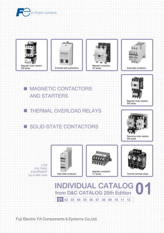
- 1. Information in this catalog is subject to change without notice. 5-7, Nihonbashi Odemma-cho, Chuo-ku, Tokyo, 103-0011, Japan URL http://www.fujielectric.co.jp/fcs/eng INDIVIDUALCATALOGfromD&CCATALOG20thEdition 01 01 02 03 04 05 06 07 08 09 10 11 12 LOW VOLTAGE EQUIPMENT Up to 600 Volts INDIVIDUAL CATALOG from D&C CATALOG 20th Edition 01INDIVIDUAL CATALOG from D&C CATALOG 20th Edition 01 MAGNETIC CONTACTORS AND STARTERS SOLID-STATE CONTACTORS THERMAL OVERLOAD RELAYS LOW VOLTAGE PRODUCTS Up to 600 Volts Individual catalog No. 01 Magnetic Contactors and Starters Thermal Overload Relays, Solid-state Contactors 02 Industrial Relays, Industrial Control Relays Annunciator Relay Unit, Time Delay Relays Manual Motor Starters and Contactors Combination Starters Pushbuttons, Selector Switches, Pilot Lights Rotary Switches, Cam Type Selector Switches Panel Switches, Terminal Blocks, Testing Terminals Molded Case Circuit Breakers Air Circuit Breakers Earth Leakage Circuit Breakers Earth Leakage Protective Relays Measuring Instruments, Arresters, Transducers Power Factor Controllers Power Monitoring Equipment (F-MPC) Circuit Protectors Low Voltage Current-Limiting Fuses 03 04 05 06 07 08 09 10 HIGH VOLTAGE PRODUCTS Up to 36kV 11 Disconnecting Switches, Power Fuses Air Load Break Switches Instrument Transformers — VT, CT D&C CATALOG DIGEST INDEX AC Power Regulators Noise Suppression Filters Control Power Transformers 12 Vacuum Circuit Breakers, Vacuum Magnetic Contactors Protective Relays Limit Switches, Proximity Switches Photoelectric Switches Magnetic contactors SC series Solid-state contactors Magnetic motor starters SW series Reversing motor starters SW series Thermal overload relays Magnetic contactors FC series Magnetic motor starters SW series Enclosed with pushbuttons Solid-state contactors 2010-09 PDF FOLS DEC2001
- 2. 2 Magnetic Contactors and Starters SC and SW series Design features SC-03, 0, 05, 4-0, 4-1, 5-1 SC-N1, N2, N2S, N3 Long electrical life 2 million operations (AC-3 duty) Easy-to-read front display Type, ratings and terminal numbers Single-side-mounted coil terminal The coil surge suppressor or coil drive unit can be easily added Terminal numbers meet IEC standards Meets international standards IEC, NEMA, BS, JIS, VDE UL, CSA, NK, BV and LR approved Bifurcated auxiliary contact with high contact reliability Optional function unit can be easily added to modify contactor immediately on site. • Auxiliary contact block fits all size contactors(03 to N3) • Snap-on mechanical interlock unit can be fixed to equal or unequal size contactors without tools. • Front-mounted operation counter Manual operator for easy circuit checking ON-OFF status indicator Direct-fitted overload relay assures time-saving assembly Manual reset button Dial protection cover prevents unauthorized current setting Exact current setting possible Description Small frame contactors with new functions join the SC series. The SC line up, which is based on high level technology, now extends from the SC-03 to the SC-N16. The SC series contactors have such options as additional auxiliary contact blocks and operation counter unit with snap-on fittings, and coil surge suppressors. Modification can be made quickly and easily on site. Improved contact materials and structure double the electrical life compared with existing contactors 2 million operations. Bifurcated type auxiliary contacts have a high degree of contact reliability. Therefore, they can be used in low-level circuits of 5V, 3mA and directly input to electronic equipment.
- 3. 3 Front mounting Auxiliary contact block 2-pole or 4-pole Operation counter This counter indicates the number of contactor ON-OFF operations to ensure easy mainte- nance and inspection. Main circuit surge suppression unit Easy modular system Side mounting Auxiliary contact block Single pole (1NO + 1NC) Mechanical interlock unit The mechanical interlock unit is used to interlock two contactors for reversing. One size fits all contactors. Main circuit surge suppression unit This unit prevents miss-operation of electronic controllers due to motor surge voltages. Top mounting Coil drive unit This unit controls ON-OFF operation for magnetic contactors with output from electronic equipment. Coil surge suppression unit This unit absorbs coil surge voltage due to contactor ON-OFF operations. Further information See page 01/69 Mechanical interlock unit Auxiliary contact block Coil surge suppression unit Coil drive unit Main circuit surge suppression unit Auxiliary contact block Auxiliary contact block Operation counter Main circuit surge suppression unit Terminal cover Dial cover Trip indicator Reset release button SC SW series
- 4. 4 The FUJI SC series conforms to and has been approved by various international standards. Notes : Conforming to Standard R : A new certification mark that indicates compliance with both Canadian and U.S.requirements. : Frame size N1 to N14 and N16(Contactor only) * : When ordering the ccc standard type, add(ccc)suffix to the type number. Magnetic Contactors and Starters SC and SW series Design features Features of the SUPER MAGNET • Operates on both AC and DC power supply • Has a wide operational voltage range • No tendency to “chatter“ • Eliminates contact welding or coil burning • Reduces power consumption In addition the FUJI SC-N series contactors employ bifurcated auxiliary contacts which improve contact performance and permit them to be used in conjunction with programmable logic controllers. FUJI SC-N series contactors are the most suitable for new FA age ap- plications which require the most advanced electronic technologies and maximum dependability. Description FUJI SC series (SC-N6 to N16) contactors have been developed and manufactured using FUJI’s most advanced electronic technologies. They employ an electronically-controlled SUPER MAGNET which is provided with a built-in IC, thus enhancing their performance and reliability. The SUPER MAGNET is based on an “AC-input, DC-operated concept“, thus allowing the coil to be energized by both AC and DC input. Moreover, once closed, sealed current is controlled by switching circuit. This permits a great reduction in power consumption – a cost-effective feature. The SC-N1 to SC-N5A do not have the SUPER MAGNET. These contactors feature compact size, arc extinguishing mechanisms with a high breaking efficiency, low power consumption, easy operation, and ratings up to 660 volts. SC-N1 to N16 Specifications Contactors Starters(open) Non-reversing reversing Non-reversing reversing No.of thermal overload relay heater elements - - 3 3 Type SC- SC- RM SW- /3H SW- RM/3H Conformed New JIS Japan IEC International BS UK EN Europe Approved UL USA R S CSA Canada CCC China * * – – EC Directives CE Marking Europe Inspection Institute TÜV Germany
- 5. 5 Advantages of SUPER MAGNET Positive pick-up and drop-out The SUPER MAGNET operation is electronically controlled. There is no unstable zone as will be seen in the diagram–an outstanding feature that other contactors can not provide. Chattering is a phenomenon which occurs when the gravitational force of the starter magnet decreases through the line voltage drop at the time of motor starting. This may cause damage such as contact welding or coil burning. The SUPER MAGNET holds without chattering even if the line voltage drops to 65% of its rated value, so preventing this type of trouble. Operation on both AC and DC inputs The rated operational voltage range of the SC-N series contactors has been greatly expanded. They operate on both AC (50/60Hz) and DC inputs. Rated Rated coil voltage, frequency voltage AC DC 24V 24–25V 50/60 Hz 24V 48V 48–50V 50/60 Hz 48V 100V 100–127V 50/60 Hz 100–120V *1 200V 200–250V 50/60 Hz 200–240V *2 300V 265–347V 50/60 Hz – 400V 380–450V 50/60 Hz – 500V 460–575V 50/60 Hz – Notes:SC-N6 to N12: 24V–575V SC-N14 to N16: 100V–575V *1 : The coil voltage from a DC power supply with single phase full-wave rectification will be 100 to 110 V. *2 : The coil voltage from a DC power supply with single phase full-wave rectification will be 200 to 220 V. Coils (SC-N6 to SC-N16) Coil voltage Gravitationalforce Contacts open Unstable zone Contacts closed Ratedvoltage Coil voltage Gravitationalforce Contacts open Contacts closed Ratedvoltage Note: Since SC series contactors are electroni- cally controlled there is no unstable zone. Power supply AC or DC Surge suppression circuit Rectifier circuit IC-circuit Voltage detector Closing signal circuit Sealing signal circuit Power switching circuit COIL Rated voltage –15% Pick-up Operation Allowable operating voltage WIDE RATINGS Allowable operating voltage +10% Volts 200 250 Example: Coil voltage 200 volts use with AC circuit 50 or 60Hz INPUT Con- tactor ON OFF Motor inrush current Line voltage NO CHATTERING ZONE 65% of rated voltage Running current Time Motorcurrent Instantaneous voltage drops Linevoltage(%) Note: No chattering occurs even if instantaneous voltage drops to 65% of rated voltage. Motor starting Existing series SC-N series Pick-up Voltage Time Coil operating signal Coil current Closing current Sealed current OFF signal Sealed Drop-out Sealed signal ON signal Rated voltage UNSTABLE ZONE Note: Unstable zone In this zone contact welding and coil burning frequency occur due to voltage drop. IC-controlled SUPER MAGNET SC SW series For further information See page 01/22
- 6. 6 Free arc space A new arc-extinguishing method, which makes full use of magnetic field analysis technology, and a new material (UL94V-0) that has been incorporated into the design of this new type of arc-extinguishing chamber to provide a free arc space. This new method and design reduces the depth size, not only of the main body, but also that of the board (Types SC-N1 to N12). Free arc space : It means arc space is not needed on making and breaking condition according to IEC 60947-4-1. (Refer to chart Arcing gas cooling block.) Terminal cover for finger protection These optional terminal covers comply with VBG4 (German Rules of Accident Prevention), IEC60529, DIN57106, VDE0106 Teil100, which are recommendations for preventing exposure to live parts. The terminal cover satisfies the requirements of Machinery Directive EN60204-1 “Direct Contact Prevention” concerning mechanical safety. Arc Arc quencher Arc runner Metal plate Direction of arcing gas emission New material utilized in the arc-extinguishing cover Movable contact Stationary contact Arc space (explanation only) (explanation only) Magnetic Contactors and Starters SC and SW series Design features Safety Insulation Improved tracking resistance Standard heat-proof material Tracking resistance of the molded parts comprising of the conductive block has been improved. Comparative Tracking Index (CTI) : 175V or higher Tracking : It means the route of the leak electric current caused on the surface of the isolation body. The molded parts used are made of heat-proof materials specified in UL94 (UL94 : STANDARD FOR SAFETY FOR TESTS FOR FLAMMABILITY OF PLASTIC MATERIALS FOR PARTS IN DEVICES AND APPLIANCES). Arc driving system Arc gas cooling system Mirror contacts (Positively safety contacts) The contactor with mirror contacts has been certified by TÜV. Mirror contact conforms to the requirement for auxiliary contact that is intended to be included in the future amendment to IEC 60947-4-1. Mirror contact : Normally closed auxiliary contact,which cannot be in closed position simultaneously with the normally open main contact.
- 7. 7 Motor starter manufactured at ISO9001 and ISO14001- certified factory Fuji Electric has been certified for both ISO9000 series and ISO14000 series compliance. Both standards are established by the International Organization for Standardization (ISO). The former is for quality control and quality assurance, while the latter is for environmental management systems. Certified for ISO9001 and ISO14001, our Fukiage Factry, which manufactures motor starters, puts great effort into establishing a highly reliable quality assurance system and a development and production structure which takes environmental protection into account. Special type “/G” for DC operation added to SC-N1 to N5 series A new type of “/G” has been added to SC-N1 to N5 types for DC operation. Power input and consumption have been considerably reduced by introducing a full voltage-applying coil. Reducing Power Consumption The use of a new type of super magnet that applies 3D magnetic field analysis has enabled greatly reducing power consumption. This reduces CO2 emissions by 33% over products with AC coils (average for SC- N1/SE to N5 (inhouse comparison)). SC SW series Utility Ecology Bifurcated auxiliary contact system Bifurcated auxiliary contact system By employing a bifurcated contact system, higher contact reliability is achieved for service at 5V DC, 3mA (Types SC-N1 to N12). 3W 4.5W 0 1 2 3 4 5(W) Power consumption is reduced by approximately 33%. SUPER MAGNET (average for SCN1/SE to N5) Products with AC coil (average for SC-N1 to N5A) CO2 is also reduced by approximately 33%
- 8. n Overview of Product Series (No.KK04-090,49 1KK05-053, 056) (No.KKD06-013, 021) SZ-A□ SZ-J□ SZ-ZM□ SZ-RM SZ-RW□ SZ-CD□ SZ-SP□ SZ-Z□ SZ-H□ Series Page 01/1 01/65 01/66 01/77 01/78 01/80 01/81 01/87 Features Main models and model numbers Models Type Models Type Magnetic Contactors and Starters Optional Units (No.KKD06-013, 021) DC Magnetic Contactors Magnetic Contactors and Starters • Electrical life: 2,000,000 operations (SC-N3 or smaller) • Bifurcated auxiliary contacts for greater reliability • Compliance with international standards (UL, CSA, IEC, LR, BV, etc.) • Easier to use (structured to enable easy coil replacement). • High operating reliability due to a super magnet with built-in IC (SC-N6 or larger). (Prevents coil burning due to voltage fluctuations and contact fusing due to floppy operation; enables using the same coils for AC/DC, increases the range, reduces switching noise, etc.) • Mirror contacts are a standard feature. • A wide range of options • Greatly increase the functionality of Magnetic Switches. • Unit construction for easy installation. • Three-direction Units that switch between front-on, side-on, and top-on operation depending on the mounting direction. • Ideal for DC motor control and DC circuits of 360 A or less. • Compact and lightweight. • Models available with DPST-NO/SPST-NC main contacts with NC contacts for a dynamic brake. • 5N and larger models feature a super magnet with a built-in IC for high operation reliability. • UL/CSA-compliant models are also available. • The best in durability, easy-to-use performance. • Compact: 2/3 or previous models • Electrical durability: 250000 • Mechanical durability: 1 million • Various terminal types available (0 type). • Screw terminals (Standard type) • Tab terminals • P.C. board direct-mounting terminals • Low-voltage-operating type: For the minimum operating voltage, stable operation is possible even if voltage drops to 75% of the rated voltage or 70% of the rated voltage when main contacts are in contact. • UL/TUV-compliant models are also available. Auxiliary contact block Operation counter unit Main circuit surge suppression unit Mechanical interlock unit Power connection kit for reversing Coil drive unit for IC output 3-pole parallel plate terminal Coil surge suppression unit Base unit for separate mounting SB-□ SB-2N/SE, SB-□ SB-□B SB-2NB/SE, SB-□B Models Type Standard type DC-operating type Standard type with DPST-NO/SPST-NC contacts DC-operating type with DPST-NO/SPST-NC contacts FC-□, FW-□ FC-0T FC-0A FC-□/G FW-□C FW-□P Models Type Standard type Tab terminal type P.C.board direct-mounting type DC-operating type Enclosed type Magnetic switch with pushbutton • Standard type • Reversible type • DC-operating type • Mechanical-latch type • Heavy starting duty type • With quick operating type thermal relay • With 2E thermal relay • With 3E relay SC-□, SW-□ SC-□RM, SW-□RM SC-□/G, SW-□/G, SC-□/SE, SW-□/SE SC-□/V,/VG,VS SW-□/3L SW-□/3Q SW-□/2E SW-□/2E+QE-20N (No.KKD05-266) SC Series (Basic Series) SB Series FC Series 8 Magnetic Contactors and Starters General information
- 9. N16 800 N12 400 N10 220 N14 600 N11 300 N8 180 N7 152 N6 125 N5 93 N4 80 05 13 0 13 03 11 Frame size Rated current (A) Frame size Rated current (A) Frame size Rated current (A) N3 65 N2 35 N1 26 N2S 50 5-1 19 4-1 19 4-0 18 SZ-L□ SZ-R□ SZ-DA SZ-T□ SZ-JC□, SZ-JW□, SZ-□J SZ-B□ SZ-RC□ SZ-F-□/M SZ-□/DE Overview Type Enables easily adding auxiliary contacts. Displays the number of switching operations of the Magnetic Contactor. Protects a three-phase motor from surge voltages. Used to interlock a reversible Magnetic Switch. Used to wire the main circuits of a reversing contactors and starters. Enables driving a coil with a transistor output. Used to assemble a stand-alone, resistive-load Magnetic Contactor. Provides protection against surge voltages with the coil is turned OFF. Used to assemble a stand-alone Thermal Relay. Overview Indicates the tripping status of the thermal relay. Used for remote control of thermal relay resetting. Prevents changes to the current setting of thermal relay. Prevents exposure of charged terminal section. Prevents exposure of charged terminal section. Prevents exposure of charged terminal section and short-circuits between phases. Prevents contact wear cause by material transfer. Detects errors in the voltage across the load. Holds the closed-circuit status during momentary power interruptions. Models Trip indicator Reset release button Dial cover Terminal cover Live-section cover Insulation barrier Contact protector Fault detector unit OFF-delay release unit 5N 85 − − − − 2N/SE 35 2N 35 − − − − − − 6N 120 10N 200 11N 290 − − − − − − − − − − − − 1S 26 2S 35 3 50 4 65 1 20 − − − − − − − − − − − − 0S 15 0T 12 0 12 0A 8 *1*1 *1 *1 Magnetic Contactors only 9 Magnetic Contactors and Starters General information
- 10. n Overview of Product Series (No.AF00-140, 144) Series Page Features Main models and types Models TypeThermal overload Relays • New models added to the series: Standard (overload protection with 3 elements), 2E (overload + phase loss), long time operation (3 elements), Quick operation. • Independent SPST-NC/SPST-NO auxiliary contacts. • Switchable between manual and automatic resetting. • A wide range of options. • These Solid-state Contactors are non-contact semiconductor contactors that provide the characteristics of magnetic contactors. • Long life and quiet operation. • Cooling fan included in one-piece structure. • AC control is also possible. • Surge absorber included. • Lineup includes models with zero-cross switching function. • A wide range of rated voltages. • Operating indicator (LED) included as standard feature. • Built-in auxiliary output module. • Standard type • 2E type • Long time operating type • Quick operating type TR-□/3, TR-□H/3 TK-□, TK-□H TR-□L/3, TR-□LH/3 TR-□Q, TR-□QH Models Type • Single-pole type (main circuit 240V AC) • Single-pole type (main circuit 480V AC) • 3-pole type (main circuit 240V AC) • 3-pole type (main circuit 480V AC) SS□1 SS□1H SS□2, SS□3 SS□2H, SS□3H 01/101 01/115 01/88 01/100 TR/TK Series Solid-state ContactorsSS Series 10 Magnetic Contactors and Starters General information
- 11. N14 240-600 N12 110-450 N10 85-240 N8 65-185 N7 45-160 N6 45-160 N5 18-105 N3 7-105 5-1N 0.1-18 0N 0.1-13 N2 4-42 SS120 120 SS150 150 SS200 200 SS100 100 SS80 80 SS70 70 SS50 50 SS40 40 SS30 30 SS20 20 SS08 8 SS03 3 SS10 10 Frame size Frame size Ampere setting range [A] Rated themal current [A] 11 Magnetic Contactors and Starters General information
- 12. SC and SW series standard type General information .......................................................................................... 01/1 Versions ............................................................................................................ 01/2 Quick selection guide Non reversing, Open type .............................................................................. 01/4 Enclosed type ........................................................................ 01/9 Reversing, Open type ..................................................................................... 01/12 Enclosed type ............................................................................... 01/15 Type number nomenclature .............................................................................. 01/17 Ordering code system ...................................................................................... 01/18 Specifications ................................................................................................... 01/20 Standard type ................................................................................................... 01/25 Reversing standard type ................................................................................... 01/34 DC operated ..................................................................................................... 01/41 OFF-delay release ............................................................................................ 01/46 With extra pick-up operating coil ...................................................................... 01/47 Mechanical latch contactors ............................................................................. 01/48 Heavy starting duty starters .............................................................................. 01/53 With quick operating overload relay ................................................................. 01/55 With phase loss protective device .................................................................... 01/56 With phase loss and phase-sequence protective device.................................. 01/58 Enclosed with pushbuttons ............................................................................... 01/60 Dust-tight/light-corrosion resistance ................................................................. 01/62 For single-phase resistance load ...................................................................... 01/63 With single button auxiliary contact .................................................................. 01/64 With quick connection terminals ....................................................................... 01/65 Optional unit ..................................................................................................... 01/66 SB series .............................................................................................................. 01/78 FC and FW series FC series .......................................................................................................... 01/81 Ordering code system ...................................................................................... 01/82 FW series ......................................................................................................... 01/84 FW series with pushbuttons ............................................................................. 01/87 TR series General information .......................................................................................... 01/88 Ordering code system ...................................................................................... 01/89 Features and optional accessories ................................................................... 01/90 Selection guide Standard type ............................................................................................... 01/91 Long time operating type .............................................................................. 01/92 Quick operating type .................................................................................... 01/93 TK series With phase loss protective device .................................................................... 01/100 SS series .............................................................................................................. 01/101 UL and CSA approved .......................................................................................... 01/116 TÜV approved....................................................................................................... 01/123 CCC approved ...................................................................................................... 01/127 SJ series ............................................................................................................... 01/130 01 Solid-state Contactors Magnetic Contactors and Starters Thermal Overload Relays DC Magnetic Contactors Magnetic Contactors and Starters Magnetic Contactors and Starters Solid-state Contactors Magnetic Contactors and Starters Page
- 13. MINIMUM ORDERS Orders amounting to less than ¥10,000 net per order will be charged as ¥10,000 net per order plus freight and other charges. WEIGHTS AND DIMENSIONS Weights and dimensions appearing in this catalog are the best information available at the time of going to press. FUJI ELECTRIC FA has a policy of continuous product improvement, and design changes may make this information out of date. Please confirm such details before planning actual construction. INFORMATION IN THIS CATALOG IS SUBJECT TO CHANGE WITHOUT NOTICE.
- 14. Fuji Electric FA Components & Systems Co., Ltd./D & C Catalog Information subject to change without notice 01/1 01 SC and SW series FC series KK05-042KK04-083 KKD05-253 FC and FW series Definite purpose contactors and starters The FC series contactors are compact and economical contactors designed for use in consumer appliances with relatively low switching frequencies. Typical applications include air condi- tioners, industrial washing machines, heaters, compressors, driers, and fans. Contactor pickup voltage is 75% of the rated voltage. FC-0 is available with tab and printed board terminals, as well as with self-lifting screw terminals. SS series Solid-state contactors The SS series contactors employ a semiconductor that can withstand both high voltage and large overcurrent when making and breaking load circuits. The completely contactless design gives high performance, including long service life and noise- free operation. Applications include frequent making and breaking for motors, heaters, and similar circuits. A built-in surge absorbing varistor and CR circuit to protect the SSC from surges when switching inductive loads, and surges from external circuits. FUJI low-voltage contactors and starters are available in a broad choice of types, from high-performance to economy, for all consumer and industrial needs. For standard applications, we offer the high- performance SC series. We offer the economical F series for light industrial use, the SB series dedicated to DC circuits, and the SS series with long service-life noise-free solid-state contactors. SC and SW series Standard type magnetic contactors and starters The SC series is a range of long service-life and high-performance contactors. SC-03 to SC-N3 small- frame contactors provide snap-on fitting of numerous optional units, such as auxiliary contact blocks, coil surge suppressors, and operation counters. Field modifications are quick and easy to make. Type SC-N6 and above contactors come with an IC-controlled SUPER MAGNET coil, which operates from both AC and DC sources, to eliminate burnt coils and contact chattering caused by voltage fluctuation. SB series DC magnetic contactors We developed the SB series DC contactors from our SC series AC contactors. Applications include opening and closing DC circuits and controlling DC motors. They permit switching of DC loads up to 550V DC, 360A. There are two main contact arrangements available: the 2NO type and the 2NO + 1NC type, which has one NC contact for dynamic brake circuits. Type SB-5N and above contactors come with an IC-controlled SUPER MAGNET coil for improved operational stability. SK-441 AF89-728 KKD06-043KKD05-254 Magnetic Contactors and Starters General information KK05-065 DUO series BM3 series manual motor starters, SC-M and SC-E series magnetic contactors Refer to the Indiviclual Catalog No.02. SB series SS series KKD05-266KKD06-052
- 15. Fuji Electric FA Components & Systems Co., Ltd./D & C Catalog Information subject to change without notice01/2 Magnetic Contactors and Starters SC and SW series Versions Standard type contactors and starters Standard type is usually used to start and stop motors, and to open and close resistance loads like heaters or electric furnaces. See page 01/25. DC-operated contactors and starters Main circuit is AC, and operation is carried out by DC operating coil. This type is useful for applications in which control power source is independent. See page 01/41. OFF-delay release contactors and starters This is a combination of DC-operated magnetic contactor and off-delay release unit. This prevents circuit opening due to instantaneous voltgage drops. See page 01/46. KK04-083 KK05-042 KKD05-270 H-AF89-76KKD06-026 Enclosed type starters Standard type starter are housed in a protective enclosure. See page 01/33. AF88-1347 Contactors and starters with SUPER MAGNET IC operated SUPER MAGNET prevents coil burning and contact welding due to voltage fluctuations See page 01/25. KK05-065 Reversing contactors and starters This type is most suitable for reversing operation of 3-phase motors or plugging or braking. See page 01/34. KKD06-064 AF88-1408 AF00-299AF88-1353 With extra pickup operating coil These contactors are suitable for use in places with poor power supply condi- tions. These contactors operate normally even if the coil input voltage falls to 75% of the coil rated voltage. See page 01/47. AF88-820 Mechanical latch contactors Latch mechanism prevents the circuit from opening due to power failure, instantaneous power failure, or voltage drop of power source. This is suitable for change-over circuit and stand-by power supply equipment. See page 01/48. Heavy starting duty starters This is suitable for overload protection or stall prevention of motors with longer starting times such as those for blowers and fans having a large inertia. See page 01/53. +
- 16. Fuji Electric FA Components & Systems Co., Ltd./D & C Catalog Information subject to change without notice 01/3 01 With quick connection terminals No removing terminal screw is required. When contactor and starters with the quick connection terminals are shipped, these screws are inserted in the terminals section but make no contact. It reduces the number of wiring steps. Terminals with finger protection enable a high level of safety. See page 01/65. UL, CSA, TÜV and CCC approved motor starters and contactors Many models of SC series conform to UL, CSA, TÜV and CCC requirements. See page 01/120. KK04-083 KK05-042 Starters with phase-loss protective device The attached 2E thermal O/L relay protects against motor overload and as well as phase-loss. See page 01/56. KK05-047 KK05-057 KK05-047 SP-1075 Starters with phase-loss and phase- sequence protective device By combining 2E thermal O/L relay and phase-sequence relay, motor overload, phase-loss and phase-sequence protection is obtained. See page 01/58. KK05-042 Starters with quick-operating overload relay With the attached quick operating type O/L relay, this is suitable for protecting submersible pumps or compressor motors with a small heat capacity. See page 01/55. Dush-tight/light-corrosion resistant type starters The enclosure is dust-tight and corro- sion-proof, and so is suitable for locations with dusty or corrosive atmospheres. See page 01/62. SD-704KKD06-010 Starters with on-off and RESET pushbuttons Pushbuttons for close and open are built in the enclosure. Suitable for simple operations. See page 01/60. Contactors for single-phase resistance load This is a standard type magnetic contactor with a 3-phase parallel plate terminal. This is most suitable for on-off operation of electric heaters, water heaters and electric lights. See page 01/63. KK04-085 AF88-510 With single-button auxiliary contacts An auxiliary contact of a standard contactor is bifurcated. All SC-03H to SC-N12H contactor, however, feature single-button auxiliary contacts with a higher current rating than the contacts used by the standard contactor. See page 01/64. KKD06-036 Magnetic Contactors and Starters SC and SW series Versions AF95-240
- 17. Fuji Electric FA Components & Systems Co., Ltd./D & C Catalog Information subject to change without notice01/4 s Types and ratings/Non-reversing, Open Frame size 03 0 05 4-0 Max. motor capacity (kW) 200–240V 2.5 3.5 3.5 4.5 380–440V 4 5.5 5.5 7.5 AC-3, IEC 60947-4-1 500–550V 4 5.5 5.5 7.5 600–660V 4 5.5 5.5 7.5 Operational current (A) 200–240V 11 13 13 18 380–440V 9 12 12 16 500–550V 7 9 9 13 600–660V 5 7 7 9 Operational current (A) AC-1 20 20 20 25 Conventional free air thermal current (A) 20 20 20 25 Auxiliary contact arrangement 1NO 1NO 1NO+1NC 1NO 1NC 1NC 2NO, 2NC 1NC Standard Contactor SC-03 SC-0 SC-05 SC-4-0 Page Starter SW-03/3H SW-0/3H SW-05/3H SW-4-0/3H 01/25 DC operated Contactor SC-03/G SC-0/G SC-05/G SC-4-0/G Page Starter SW-03/G3H SW-0/G3H SW-05/G3H SW-4-0/G3H 01/41 OFF-delay release *1 Contactor SC-03/G+SZ-DEǢ SC-0/G+SZ-DEǢ SC-05/G+SZ-DEǢ SC-4-0/G+SZ-DEǢ Page Starter SW-03/G3H+ SW-0/G3H+ SW-05/G3H+ SW-4-0/G3H+ 01/46 SZ-DEǢ SZ-DEǢ SZ-DEǢ SZ-DEǢ With extra pick-up Contactor SC-03/U SC-0/U SC-05/U SC-4-0/U Page operating coil Starter SW-03/U3H SW-0/U3H SW-05/U3H SW-4-0/U3H 01/47 Mechanical latch Contactor SC-03/V SC-0/V SC-05/V SC-4-0/V Page AC operated Starter – – – – 01/48 Mechanical latch Contactor SC-03/VG SC-0/VG SC-05/VG SC-4-0/VG Page DC operated Starter – – – – 01/46 Heavy starting duty Contactor – – – – Page Starter SW-03/3L SW-0/3L SW-05/3L SW-4-0/3L 01/53 With quick operating Contactor – – – – Page overload relay Starter SW-03/3Q SW-0/3Q SW-05/3Q SW-4-0/3Q 01/55 With phase-loss Contactor – – – – Page protective device Starter SW-03/2E SW-0/2E SW-05/2E SW-4-0/2E 01/56 With phase-loss and Contactor – – – – Page phase sequence Starter SW-03/2E+QE-Ǣ0N SW-0/2E+QE-Ǣ0N SW-05/2E+QE-Ǣ0N SW-4-0/2E+QE-Ǣ0N 01/58 protective device *2 For single-phase Contactor SC-03+SZ-SP1 SC-0+SZ-SP1 SC-05+SZ-SP1 SC-4-0+SZ-SP2 Page resistance load Starter – – – – 01/63 With quick counection Contactor SC-03Y SC-0Y SC-05Y – Page terminals starter SW-03Y SW-0Y SW-05Y – 01/65 Thermal overload relay Page On-contactor mounting 01/88 Standard TR-0N/3 TR-0N/3 TR-0N/3 TR-5-1N/3 Long time operation TR-0NL/3 TR-0NL/3 TR-0NL/3 TR-5-1NL/3 Quick operation TR-0NQ TR-0NQ TR-0NQ TR-5-1NQ Phase-loss protection TK-0N TK-0N TK-0N TK-5-1N Further information Magnetic Contactors and Starters SC and SW series Quick selection guide/Open type Note: *1 Replace the Ǣ mark in the type number by the operating voltage code. 100V AC: 100, 110V AC: 110, 200V AC: 200, 220V AC: 220 *2 Replace the Ǣ mark in the type number by the operating voltage code. 200-220V AC: 2, 380-415V AC: 4
- 18. Fuji Electric FA Components & Systems Co., Ltd./D & C Catalog Information subject to change without notice 01/5 01 Magnetic Contactors and Starters SC and SW series Quick selection guide/Open type s Types and ratings/Non-reversing, Open Frame size 4-1 5-1 N1 N2 Max. motor capacity (kW) 200–240V 5.5 5.5 7.5 11 380–440V 11 11 15 18.5 AC-3, IEC 60947-4-1 500–550V 11 11 15 18.5 600–660V 7.5 7.5 11 15 Operational current (A) 200–240V 22 22 32 40 380–440V 22 22 32 40 500–550V 17 17 24 29 600–660V 9 9 15 19 Operational current (A) AC-1 32 32 50 60 Conventional free air thermal current (A) 32 32 50 60 Auxiliary contact arrangement 1NO 1NO+1NC, 2NO 2NO+2NC 2NO+2NC 1NC 2NO+2NC, 2NC 4NO+4NC 4NO+4NC Standard Contactor SC-4-1 SC-5-1 SC-N1 SC-N2 Page Starter SW-4-1/3H SW-5-1/3H SW-N1/3H SW-N2/3H 01/25 DC operated Contactor SC-4-1/G SC-5-1/G SC-N1/G SC-N2/G Page Starter SW-4-1/G3H SW-5-1/G3H SW-N1/G3H SW-N2/G3H 01/41 OFF-delay release *1 Contactor SC-4-1/G+SZ-DEǢ SC-5-1/G+SZ-DEǢ SC-N1/G+ SC-N2/G+ Page SZ-N1/GDE SZ-N1/GDE 01/46 Starter SW-4-1/G3H+ SW-5-1/G3H+ SW-N1/G3H+ SW-N2/G3H+ SZ-DEǢ SZ-DEǢ SZ-N1/GDE SZ-N1/GDE With extra pick-up Contactor SC-4-1/U SC-5-1/U SC-N1/U SC-N2/U Page operating coil Starter SW-4-1/U3H SW-5-1/U3H SW-N1/U3H SW-N2/U3H 01/47 Mechanical latch Contactor SC-4-1/V SC-5-1/V SC-N1/VS SC-N2/VS Page AC operated Starter – – – – 01/48 Mechanical latch Contactor SC-4-1/VG SC-5-1/VG SC-N1/VS SC-N2/VS Page DC operated Starter – – – – 01/48 Heavy starting duty Contactor – – – – Page Starter SW-4-1/3L SW-5-1/3L SW-N1/3L SW-N2/3L 01/53 With quick operating Contactor – – – – Page overload relay Starter SW-4-1/3Q SW-5-1/3Q SW-N1/3Q SW-N2/3Q 01/55 With phase-loss Contactor – – – – Page protective device Starter SW-4-1/2E SW-5-1/2E SW-N1/2E SW-N2/2E 01/56 With phase-loss and Contactor – – – – Page phase sequence Starter SW-4-1/2E+QE-Ǣ0N SW-5-1/2E+QE-Ǣ0N SW-N1/2E+QE-Ǣ0N SW-N2/2E+QE-Ǣ0N 01/58 protective device *2 For single-phase Contactor SC-4-1+SZ-SP2 SC-5-1+SZ-SP2 SC-N1+SZ-SP3 SC-N2+SZ-SP3 Page resistance load Starter – – – – 01/63 With quick counection Contactor – SC-5-1Y – – Page terminals starter – SW-5-1Y – – 01/65 Thermal overload relay Page On-contactor mounting 01/88 Standard TR-5-1N/3 TR-5-1N/3 TR-N2/3 TR-N2/3 Long time operation TR-5-1NL/3 TR-5-1NL/3 TR-N2L/3 TR-N2L/3 Quick operation TR-5-1NQ TR-5-1NQ TR-N2Q TR-N2Q Phase-loss protection TK-5-1N TK-5-1N TK-N2 TK-N2 Further information Note: *1 Replace the Ǣ mark in the type number by the operating voltage code. 100V AC: 100, 110V AC: 110, 200V AC: 200, 220V AC: 220 *2 Replace the Ǣ mark in the type number by the operating voltage code. 200-220V AC: 2, 380-415V AC: 4
- 19. Fuji Electric FA Components & Systems Co., Ltd./D & C Catalog Information subject to change without notice01/6 s Types and ratings/Non-reversing, Open Frame size N2S N3 N4 N5A Max. motor capacity (kW) 200–240V 15 18.5 22 30 380–440V 22 30 40 55 AC-3, IEC 60947-4-1 500–550V 25 37 37 55 600–660V 22 30 37 55 Operational current (A) 200–240V 50 65 80 105 380–440V 50 65 80 105 500–550V 38 60 60 85 600–660V 26 38 44 64 Operational current (A) AC-1 80 100 135 150 Conventional free air thermal current (A) 80 100 135 150 Auxiliary contact arrangement 2NO+2NC 2NO+2NC 2NO+2NC 2NO+2NC 4NO+4NC 4NO+4NC 4NO+4NC 4NO+4NC Standard Contactor SC-N2S SC-N3 SC-N4 SC-N5A Page Starter SW-N2S/3H SW-N3/3H SW-N4/3H SW-N5A/3H 01/25 DC operated Contactor SC-N2S/G SC-N3/G SC-N4/G SC-N5/G Page Starter SW-N2S/G3H SW-N3/G3H SW-N4/G3H SW-N5/G3H 01/41 OFF-delay release Contactor SC-N2S/G+ SC-N3/G+ SC-N4/SE+ SC-N5+ Page SZ-N2S/GDE SZ-N2S/GDE SZ-N5/DE SZ-N5/DE 01/46 Starter SW-N2S/G3H+ SW-N3/G3H+ SW-N4/SE3H+ SW-N5/3H+ SZ-N2S/GDE SZ-N2S/GDE SZ-N5/SEDE SZ-N5/DE With extra pick-up *1 Contactor SC-N2S/U SC-N3/U SC-N4/U – Page operating coil Starter SW-N2S/U3H SW-N3/U3H SW-N4/U3H – 01/47 Mechanical latch Contactor SC-N2S/VS SC-N3/VS SC-N4/VS SC-N5/VS Page AC operated Starter – – – – 01/48 Mechanical latch Contactor SC-N2S/VS SC-N3/VS SC-N4/VS SC-N5/VS Page DC operated Starter – – – – 01/48 Heavy starting duty Contactor – – – – Page Starter SW-N2S/3L SW-N3/3L SW-N4/3L SW-N5A/3L 01/53 With quick operating Contactor – – – – Page overload relay Starter SW-N2S/3Q SW-N3/3Q SW-N4/3Q SW-N5A/3Q 01/55 With phase-loss Contactor – – – – Page protective device Starter SW-N2S/2E SW-N3/2E SW-N4/2E SW-N5A/2E 01/56 With phase-loss and Contactor – – – – Page phase sequence Starter SW-N2S/2E+QE-Ǣ0N SW-N3/2E+QE-Ǣ0N SW-N4/2E+QE-Ǣ0N SW-N5A/2E+QE-Ǣ0N 01/58 protective device *2 For single-phase Contactor SC-N2S+SZ-SP4 SC-N3+SZ-SP4 SC-N4+SZ-SP5 SC-N5A+SZ-SP5 Page resistance load Starter – – – – 01/63 Thermal overload relay Page On-contactor mounting 01/88 Standard TR-N3/3 TR-N3/3 TR-N5/3 TR-N5/3 Long time operation TR-N3L/3 TR-N3L/3 TR-N5L/3 TR-N5L/3 Quick operation TR-N3Q TR-N3Q TR-N5Q TR-N5Q Phase-loss protection TK-N3 TK-N3 TK-N5 TK-N5 Further information Magnetic Contactors and Starters SC and SW series Quick selection guide/Open type Note: *1 The standard types for frame sizes N6 and above (with SUPER MAGNET) hold without chattering even if the line voltage drops to 65% of its rated value. *2 Replace the Ǣ mark in the type namber by the operating voltage code. 200-220V AC: 2, 380-415V AC: 4
- 20. Fuji Electric FA Components & Systems Co., Ltd./D & C Catalog Information subject to change without notice 01/7 01 s Types and ratings/Non-reversing, Open Frame size N6 N7 N8 N10 Max. motor capacity (kW) 200–240V 37 45 55 65 380–440V 60 75 90 110 AC-3, CEC 60947-4-1 500–550V 60 75 130 132 600–660V 60 90 132 132 Operational current (A) 200–240V 125 150 180 220 380–440V 125 150 180 220 500–550V 90 120 180 200 600–660V 72 103 150 150 Operational current (A) AC-1 150 200 260 260 Conventional free air thermal current (A) 150 200 260 260 Auxiliary contact arrangement 2NO+2NC 2NO+2NC 2NO+2NC 2NO+2NC 4NO+4NC 4NO+4NC 4NO+4NC 4NO+4NC Standard Contactor SC-N6 SC-N7 SC-N8 SC-N10 Page Starter SW-N6/3H SW-N7/3H SW-N8/3H SW-N10/3H 01/25 DC operated Contactor SC-N6 SC-N7 SC-N8 SC-N10 Page Starter SW-N6/3H SW-N7/3H SW-N8/3H SW-N10/3H 01/41 OFF-delay release Contactor SC-N6+SZ-N6/DE SC-N7+SZ-N6/DE SC-N8+SZ-N8/DE SC-N10+SZ-N8/DE Page Starter SW-N6/3H+ SW-N7/3H+ SW-N8/3H+ SW-N10/3H+ 01/46 SZ-N6/DE SZ-N6/DE SZ-N8/DE SZ-N8/DE With extra pick-up *1 Contactor – – – – – operating coil Starter – – – – – Mechanical latch/ Contactor SC-N6/VS SC-N7/VS SC-N8/VS SC-N10/VS Page AC operated Starter – – – – 01/48 Mechanical latch/ Contactor SC-N6/VS SC-N7/VS SC-N8/VS SC-N10/VS Page DC operated Starter – – – – 01/48 Heavy starting duty Contactor – – – – Page Starter SW-N6/3L SW-N7/3L SW-N8/3L SW-N10/3L 01/53 With quick operating Contactor – – – – Page overload relay Starter – – – – 01/55 With phase-loss Contactor – – – – Page protective device Starter SW-N6/2E SW-N7/2E SW-N8/2E SW-N10/2E 01/56 With phase-loss and Contactor – – – – Page phase sequence Starter SW-N6/2E+QE-Ǣ0N SW-N7/2E+QE-Ǣ0N SW-N8/2E+QE-Ǣ0N SW-N10/2E+QE-Ǣ0N 01/58 protective device *2 For single-phase Contactor SC-N6+SZ-SP7 SC-N7+SZ-SP7 SC-N8+SZ-SP8 SC-N10+SZ-SP8 Page resistance load Starter – – – – 01/63 Thermal overload relay Page On-contactor mounting 01/88 Standard TR-N6/3 TR-N7/3 TR-N8/3 TR-N10/3 Long time operation TR-N6L/3 TR-N7L/3 TR-N10L/3 TR-N10L/3 Quick operation – – – – Phase-loss protection TK-N6 TK-N7 TK-N8 TK-N10 Further information Note: *1 The standard types for frame sizes N6 and above (with SUPER MAGNET) hold without chattering even if the line voltage drops to 65% of its rated value. *2 Replace the Ǣ mark in the type namber by the operating voltage code. 200-220V AC: 2, 380-415V AC: 4 Magnetic Contactors and Starters SC and SW series Quick selection guide/Open type
- 21. Fuji Electric FA Components & Systems Co., Ltd./D & C Catalog Information subject to change without notice01/8 s Types and ratings/Non-reversing, Open Frame size N11 N12 N14 N16 Max. motor capacity (kW) 200–240V 90 120 180 220 380–440V 160 220 315 440 AC-3, IEC 60947-4-1 500–550V 160 250 400 500 600–660V 200 300 480 500 Operational current (A) 200–240V 300 400 600 800 380–440V 300 400 600 800 500–550V 230 360 600 720 600–660V 230 360 600 630 Operational current (A) AC-1 350 450 660 800 Conventional free air thermal current (A) 350 450 660 800 Auxiliary contact arrangement 2NO+2NC 2NO+2NC 2NO+2NC 2NO+2NC 4NO+4NC 4NO+4NC 4NO+4NC 4NO+4NC Standard Contactor SC-N11 SC-N12 SC-N14 SC-N16 Page Starter SW-N11/3H SW-N12/3H SW-N14/3H – 01/25 DC operated Contactor SC-N11 SC-N12 SC-N14 SC-N16 Page Starter SW-N11/3H SW-N12/3H SW-N14/3H – 01/41 OFF-delay release Contactor SC-N11+SZ-N11/DE SC-N12+SZ-N11/DE SC-N14+SZ-N14/DE – Page Starter SW-N11/3H+ SW-N12/3H+ SW-N14/3H+ – 01/46 SZ-N11/DE SZ-N11/DE SZ-N14/DE – With extra pick-up *1 Contactor – – – – – operating coil Starter – – – – – Mechanical latch Contactor SC-N11/VS SC-N12/VS SC-N14/VS – Page AC operated Starter – – – – 01/48 Mechanical latch Contactor SC-N11/VS SC-N12/VS SC-N14/VS – Page DC operated Starter – – – – 01/48 Heavy starting duty Contactor – – – – Page Starter SW-N11/3L SW-N12/3L SW-N14/3L – 01/53 With quick operating Contactor – – – – – overload relay Starter – – – – – With phase-loss Contactor – – – – Page protective device Starter SW-N11/2E SW-N12/2E SW-N14/2E – 01/56 With phase-loss and Contactor – – – – Page phase sequence Starter SW-N11/2E+QE-Ǣ0N SW-N12/2E+QE-Ǣ0N SW-N14/2E+QE-Ǣ0N – 01/58 protective device *2 For single-phase Contactor SC-N11+SZ-SP9 SC-N12+SZ-SP9 SC-N14+SZ-SP10 SC-N16+SZ-SP10 Page resistance load Starter – – – – 01/63 Thermal overload relay Page On-contactor mounting 01/88 Standard TR-N12/3 TR-N12/3 TR-N14/3 – Long time operation TR-N12L/3 TR-N12L/3 TR-N14L/3 – Quick operation – – – – Phase-loss protection TK-N12 TK-N12 TK-N14 – Further information Magnetic Contactors and Starters SC and SW series Quick selection guide/Open type Note: *1 The standard types for frame sizes N6 and above (with SUPER MAGNET) hold without chattering even if the line voltage drops to 65% of its rated value. *2 Replace the Ǣ mark in the type namber by the operating voltage code. 200-220V AC: 2, 380-415V AC: 4
- 22. Fuji Electric FA Components & Systems Co., Ltd./D & C Catalog Information subject to change without notice 01/9 01 s Types and ratings/Non-reversing, Enclosed Frame size 03 0 05 4-0 Max. motor capacity (kW) 200–240V 2.5 3.5 3.5 4.5 380–440V 4 5.5 5.5 7.5 AC-3, IEC 60947-4-1 500–550V 4 5.5 5.5 7.5 600–660V 4 5.5 5.5 7.5 Operational current (A) 200–240V 11 13 13 18 380–440V 9 12 12 16 500–550V 7 9 9 13 600–660V 5 7 7 9 Operational current (A) AC-1 20 20 20 25 Conventional free air thermal current (A) 20 20 20 25 Auxiliary contact arrangement 1NO 1NO 1NO+1NC 1NO 1NC 1NC 2NO, 2NC 1NC Standard Contactor SC-03C SC-0C SC-05C SC-4-0C Page Starter SW-03C/3H SW-0C/3H SW-05C/3H SW-4-0C/3H 01/25 With extra pick-up Contactor – – – – Page operating coil Starter SW-03C/U3H SW-0C/U3H SW-05C/U3H SW-4-0C/U3H 01/47 With phase-loss Contactor – – – – Page protective device Starter SW-03C/2E SW-0C/2E SW-05C/2E SW-4-0C/2E 01/56 With ON-OFF/reset Contactor – – – – Page pushbuttons Starter SW-03P/3H SW-0P/3H SW-05P/3H SW-4-0P/3H 01/60 Dust tight/light Contactor – – – – Page corrosion resistant Starter SW-03LG/3H SW-0LG/3H SW-05LG/3H SW-4-0LG/3H 01/62 Thermal overload relay See page 01/12. Same as the open types Page 01/88 Further information Magnetic Contactors and Starters SC and SW series Quick selection guide/Enclosed type Frame size 4-1 5-1 N1 N2 Max. motor capacity (kW) 200–240V 5.5 5.5 7.5 11 380–440V 11 11 15 18.5 AC-3, IEC 60947-4-1 500–550V 11 11 15 18.5 600–660V 7.5 7.5 11 15 Operational current (A) 200–240V 22 22 32 40 380–440V 22 22 32 40 500–550V 17 17 24 29 600–660V 9 9 15 19 Operational current (A) AC-1 32 32 50 60 Conventional free air thermal current (A) 32 32 50 60 Auxiliary contact arrangement 1NO 1NO+1NC 2NO+2NC 2NO+2NC 1NC 2NO, 2NC 4NO+4NC 4NO+4NC Standard Contactor SC-4-1C SC-5-1C SC-N1C SC-N2C Page Starter SW-4-1C/3H SW-5-1C/3H SW-N1C/3H SW-N2C/3H 01/25 With extra pick-up Contactor – – – – Page operating coil Starter SW-4-1C/U3H SW-5-1C/U3H SW-N1C/U3H SW-N2C/U3H 01/47 With phase-loss Contactor – – – – Page protective device Starter SW-4-1C/2E SW-5-1C/2E SW-N1C/2E SW-N2C/2E 01/56 With ON-OFF Contactor – – – – Page pushbuttons Starter – – SW-N1P/3H SW-N2P/3H 01/60 With ON-OFF/reset Contactor – – – – Page pushbuttons Starter SW-4-1P/3H SW-5-1P/3H SW-N1PB/3H SW-N2PB/3H 01/60 Dust tight/light Contactor – – – – Page corrosion resistant Starter SW-4-1LG/3H SW-5-1LG/3H SW-N1LG/3H SW-N2LG/3H 01/62 Thermal overload relay See page 01/12. Same as the open types Page 01/88 Further information
- 23. Fuji Electric FA Components & Systems Co., Ltd./D & C Catalog Information subject to change without notice01/10 s Types and ratings/Non-reversing, Enclosed Frame size N2S N3 N4 N5A Max. motor capacity (kW) 200–240V 15 18.5 22 30 380–440V 22 30 40 55 AC-3, IEC 60947-4-1 500–550V 25 37 37 55 600–660V 22 30 37 55 Operational current (A) 200–240V 50 65 80 105 380–440V 50 65 80 105 500–550V 38 60 60 85 600–660V 26 38 44 64 Operational current (A) AC-1 80 100 135 150 Conventional free air thermal current (A) 80 100 135 150 Auxiliary contact arrangement 2NO+2NC 2NO+2NC 2NO+2NC 2NO+2NC 4NO+4NC 4NO+4NC 4NO+4NC 4NO+4NC Standard Contactor SC-N2SC SC-N3C SC-N4C SC-N5AC Page Starter SW-N2SC/3H SW-N3C/3H SW-N4C/3H SW-N5AC/3H 01/25 With extra pick-up Contactor – – – – Page operating coil * Starter SW-N2SC/U3H SW-N3C/U3H SW-N4C/SE3H – 01/47 With phase-loss Contactor – – – – Page protective device Starter SW-N2SC/2E SW-N3C/2E SW-N4C/2E SW-N5AC/2E 01/56 With ON-OFF Contactor – – – – Page pushbuttons Starter SW-N2SP/3H SW-N3P/3H – – 01/60 With ON-OFF and reset Contactor – – – – Page pushbuttons Starter SW-N2SPB/3H SW-N3PB/3H SW-N4PB/3H SW-N5PB/3H 01/60 Dust tight/light Contactor – – – – Page corrosion resistant Starter SW-N2SLG/3H SW-N3LG/3H SW-N4LG/3H SW-N5ALG/3H 01/62 Thermal overload relay See page 01/13. Same as the open types Page 01/88 Further information Magnetic Contactors and Starters SC and SW series Quick selection guide/Enclosed type Frame size N6 N7 N8 N10 Max. motor capacity (kW) 200–240V 37 45 55 65 380–440V 60 75 90 110 AC-3, IEC 60947-4-1 500–550V 60 75 130 132 600–660V 60 90 132 132 Operational current (A) 200–240V 125 150 180 220 380–440V 125 150 180 220 500–550V 90 120 180 200 600–660V 72 103 150 150 Operational current (A) AC-1 150 200 260 260 Conventional free air thermal current (A) 150 200 260 260 Auxiliary contact arrangement 2NO+2NC 2NO+2NC 2NO+2NC 2NO+2NC 4NO+4NC 4NO+4NC 4NO+4NC 4NO+4NC Standard Contactor SC-N6C SC-N7C SC-N8C SC-N10C Page Starter SW-N6C/3H SW-N7C/3H SW-N8C/3H SW-N10C/3H 01/25 With extra pick-up Contactor – – – – – operating coil * Starter – – – – – With phase-loss Contactor – – – – Page protective device Starter SW-N6C/2E SW-N7C/2E SW-N8C/2E SW-N10C/2E 01/56 With ON-OFF Contactor – – – – – pushbuttons Starter – – – – – With ON-OFF and reset Contactor – – – – Page pushbuttons Starter SW-N6PB/3H – SW-N8PB/3H SW-N10PB/3H 01/60 Dust tight/light Contactor – – – – Page corrosion resistant Starter SW-N6LG/3H SW-N7LG/3H SW-N8LG/3H SW-N10LG/3H 01/62 Thermal overload relay See page 01/13. Same as the open types Page 01/88 Further information Note: * The standard types for frame sizes N6 and above (with SUPER MAGNET) hold without chattering even if the line voltage drops to 65% of its rated value.
- 24. Fuji Electric FA Components & Systems Co., Ltd./D & C Catalog Information subject to change without notice 01/11 01 s Types and ratings/Non-reversing, Enclosed Frame size N11 N12 N14 N16 Max. motor capacity (kW) 200–240V 90 120 180 – 380–440V 160 220 315 – AC-3, IEC 60947-4-1 500–550V 160 250 400 – 600–660V 200 300 480 – Operational current (A) 200–240V 300 400 600 – 380–440V 300 400 600 – 500–550V 230 360 600 – 600–660V 230 360 600 – Operational current (A) AC-1 350 450 660 – Conventional free air thermal current (A) 350 450 660 – Auxiliary contact arrangement 2NO+2NC 2NO+2NC 2NO+2NC – 4NO+4NC 4NO+4NC 4NO+4NC – Standard Contactor SC-N11C SC-N12C SC-N14C – Page Starter SW-N11C/3H SW-N12C/3H SW-N14C/3H – 01/25 With extra pick-up Contactor – – – – – operating coil * Starter – – – – – With phase-loss Contactor – – – – Page protective device Starter SW-N11C/2E SW-N12C/2E SW-N14C/2E – 01/56 With ON-OFF Contactor – – – – – pushbuttons Starter – – – – – With ON-OFF and reset Contactor – – – – – pushbuttons Starter – – – – – Dust tight/light Contactor – – – – – corrosion resistant Starter – – – – – Thermal overload relay See page 01/14. Same as the open types Page 01/88 Further information Magnetic Contactors and Starters SC and SW series Quick selection guide/Enclosed type Note: * The standard types for frame sizes N6 and above (with SUPER MAGNET) hold without chattering even if the line voltage drops to 65% of its rated value.
- 25. Fuji Electric FA Components & Systems Co., Ltd./D & C Catalog Information subject to change without notice01/12 s Types and ratings/Reversing, Open Frame size 03 0 05 4-0 Max. motor capacity (kW) 200–240V 2.5 3.5 3.5 4.5 380–440V 4 5.5 5.5 7.5 AC-3, IEC 60947-4-1 500–550V 4 5.5 5.5 7.5 600–660V 4 5.5 5.5 7.5 Operational current (A) 200–240V 11 13 13 18 380–440V 9 12 12 16 500–550V 7 9 9 13 600–660V 5 7 7 9 Conventional free air thermal current (A) 20 20 20 25 Auxiliary contact arrangement 1NC×2 1NC×2 (1NO+1NC)×2 1NC×2 1NO×2 1NO×2 2NC×2 1NO×2 Standard Contactor SC-03RM SC-0RM SC-05RM SC-4-0RM Page Starter SW-03RM/3H SW-0RM/3H SW-05RM/3H SW-4-0RM/3H 01/34 DC operated Contactor SC-03RM/G SC-0RM/G SC-05RM/G SC-4-0RM/G Contact Starter SW-03RM/G3H SW-0RM/G3H SW-05RM/G3H SW-4-0RM/G3H FUJI Mechanical latch Contactor SC-03RM/V SC-0RM/V SC-05RM/V SC-4-0RM/V Page AC operated Starter – – – – 01/48 Mechanical latch Contactor SC-03RM/VG SC-0RM/VG SC-05RM/VG SC-4-0RM/VG Page DC operated Starter – – – – 01/48 With phase-loss Contactor – – – – Page protective device Starter SW-03RM/2E SW-0RM/2E SW-05RM/2E SW-4-0RM/2E 01/56 Thermal overload relay Page On-contactor mounting 01/88 Standard TR-0N/3 TR-0N/3 TR-0N/3 TR-5-1N/3 Phase-loss protection TK-0N TK-0N TK-0N TK-5-1N Further information Magnetic Contactors and Starters SC and SW series Quick selection guide/Reversing, Open type Frame size 4-1 5-1 N1 N2 Max. motor capacity (kW) 200–240V 5.5 5.5 7.5 11 380–440V 11 11 15 18.5 AC-3, IEC 60947-4-1 500–550V 11 11 15 18.5 600–660V 7.5 7.5 11 15 Operational current (A) 200–240V 22 22 32 40 380–440V 22 22 32 40 500–550V 17 17 24 29 600–660V 9 9 15 19 Conventional free air thermal current (A) 32 32 50 60 Auxiliary contact arrangement 1NC×2 (1NO+1NC)×2,2NC×2 (2NO+2NC)×2 (2NO+2NC)×2 1NO×2 (2NO+2NC)×2 (3NO+3NC)×2 (3NO+3NC)×2 Standard Contactor SC-4-1RM SC-5-1RM SC-N1RM SC-N2RM Page Starter SW-4-1RM/3H SW-5-1RM/3H SW-N1RM/3H SW-N2RM/3H 01/34 DC operated Contactor SC-4-1RM/G SC-5-1RM/G SC-N1RM/G SC-N2RM/G Contact Starter SW-4-1RM/G3H SW-5-1RM/G3H SW-N1RM/G3H SW-N2RM/G3H FUJI Mechanical latch Contactor SC-4-1RM/V SC-5-1RM/V SC-N1RM/VS SC-N2RM/VS Page AC operated Starter – – – – 01/48 Mechanical latch Contactor SC-4-1RM/VG SC-5-1RM/VG SC-N1RM/VS SC-N2RM/VS Page DC operated Starter – – – – 01/48 With phase-loss Contactor – – – – Page protective device Starter SW-4-1RM/2E SW-5-1RM/2E SW-N1RM/2E SW-N2RM/2E 01/56 Thermal overload relay Page On-contactor mounting 01/88 Standard TR-5-1N/3 TR-5-1N/3 TR-N2/3 TR-N2/3 Phase-loss protection TK-5-1N TK-5-1N TK-N2 TK-N2 Further information Note: Auxiliary contact arrangements indicate the ones for types except mechanical latch types.
- 26. Fuji Electric FA Components & Systems Co., Ltd./D & C Catalog Information subject to change without notice 01/13 01 s Types and ratings/Reversing, Open Frame size N2S N3 N4 N5A Max. motor capacity (kW) 200–240V 15 18.5 22 30 380–440V 22 30 40 55 AC-3, IEC 60947-4-1 500–550V 25 37 37 55 600–660V 22 30 37 55 Operational current (A) 200–240V 50 65 80 105 380–440V 50 65 80 105 500–550V 38 60 60 85 600–660V 26 38 44 64 Conventional free air thermal current (A) 80 100 135 150 Auxiliary contact arrangement (2NO+2NC)×2 (2NO+2NC)×2 (2NO+2NC)×2 (2NO+2NC)×2 (3NO+3NC)×2 (3NO+3NC)×2 (3NO+3NC)×2 (3NO+3NC)×2 Standard Contactor SC-N2SRM SC-N3RM SC-N4RM SC-N5ARM Page Starter SW-N2SRM/3H SW-N3RM/3H SW-N4RM/3H SW-N5ARM/3H 01/34 DC operated Contactor SC-N2SRM/G SC-N3RM/G SC-N4RM/G SC-N5RM/G Contact Starter SW-N2SRM/G3H SW-N3RM/G3H SW-N4RM/G3H SW-N5RM/G3H FUJI Mechanical latch Contactor SC-N2SRM/VS SC-N3RM/VS SC-N4RM/VS SC-N5RM/VS Page AC operated Starter – – – – 01/48 Mechanical latch Contactor SC-N2SRM/VS SC-N3RM/VS SC-N4RM/VS SC-N5RM/VS Page DC operated Starter – – – – 01/48 With phase-loss Contactor – – – – Page protective device Starter SW-N2SRM/2E SW-N3RM/2E SW-N4RM/2E SW-N5ARM/2E 01/56 Thermal overload relay Page On-contactor mounting 01/88 Standard TR-N3/3 TR-N3/3 TR-N5/3 TR-N5/3 Phase-loss protection TK-N3 TK-N3 TK-N5 TK-N5 Further information Frame size N6 N7 N8 N10 Max. motor capacity (kW) 200–240V 37 45 55 65 380–440V 60 75 90 110 AC-3, IEC 60947-4-1 500–550V 60 75 130 132 600–660V 60 90 132 132 Operational current (A) 200–240V 125 150 180 220 380–440V 125 150 180 220 500–550V 90 120 180 200 600–660V 72 103 150 150 Conventional free air thermal current (A) 150 200 260 260 Auxiliary contact arrangement (2NO+2NC)×2 (2NO+2NC)×2 (2NO+2NC)×2 (2NO+2NC)×2 (3NO+3NC)×2 (3NO+3NC)×2 (3NO+3NC)×2 (3NO+3NC)×2 Standard Contactor SC-N6RM SC-N7RM SC-N8RM SC-N10RM Page Starter SW-N6RM/3H SW-N7RM/3H SW-N8RM/3H SW-N10RM/3H 01/34 DC operated Contactor SC-N6RM SC-N7RM SC-N8RM SC-N10RM Contact Starter SW-N6RM/3H SW-N7RM/3H SW-N8RM/3H SW-N10RM/3H FUJI Mechanical latch Contactor SC-N6RM/VS SC-N7RM/VS SC-N8RM/VS SC-N10RM/VS Page AC operated Starter – – – – 01/48 Mechanical latch Contactor SC-N6RM/VS SC-N7RM/VS SC-N8RM/VS SC-N10RM/VS Page DC operated Starter – – – – 01/48 With phase-loss Contactor – – – – Page protective device Starter SW-N6RM/2E SW-N7RM/2E SW-N8RM/2E SW-N10RM/2E 01/56 Thermal overload relay Page On-contactor mounting 01/88 Standard TR-N6/3 TR-N7/3 TR-N8/3 TR-N10/3 Phase-loss protection TK-N6 TK-N7 TK-N8 TK-N10 Further information Note: Auxiliary contact arrangements indicate the ones for types except mechanical latch types. Magnetic Contactors and Starters SC and SW series Quick selection guide/Reversing, Open type
- 27. Fuji Electric FA Components & Systems Co., Ltd./D & C Catalog Information subject to change without notice01/14 s Types and ratings/Reversing, Open Frame size N11 N12 N14 N16 Max. motor capacity (kW) 200–240V 90 120 180 – 380–440V 160 220 315 – AC-3, IEC 60947-4-1 500–550V 160 250 400 – 600–660V 200 300 480 – Operational current (A) 200–240V 300 400 600 – 380–440V 300 400 600 – 500–550V 230 360 600 – 600–660V 230 360 600 – Conventional free air thermal current (A) 350 450 660 – Auxiliary contact arrangement (2NO+2NC)×2 (2NO+2NC)×2 (2NO+2NC)×2 – (3NO+3NC)×2 (3NO+3NC)×2 (3NO+3NC)×2 – Standard Contactor SC-N11RM SC-N12RM SC-N14RM – Page Starter SW-N11RM/3H SW-N12RM/3H SW-N14RM/3H – 01/34 DC operated Contactor SC-N11RM SC-N12RM SC-N14RM – Contact Starter SW-N11RM/3H SW-N12RM/3H SW-N14RM/3H – FUJI Mechanical latch Contactor SC-N11RM/VS SC-N12RM/VS SC-N14RM/VS – Page AC operated Starter – – – – 01/48 Mechanical latch Contactor SC-N11RM/VS SC-N12RM/VS SC-N14RM/VS – Page DC operated Starter – – – – 01/48 With phase-loss Contactor – – – – Page protective device Starter SW-N11RM/2E SW-N12RM/2E SW-N14RM/2E – 01/56 Thermal overload relay Page On-contactor mounting 01/88 Standard TR-N11/3 TR-N12/3 TR-N14/3 – Phase-loss protection TK-N11 TK-N12 TK-N14 – Further information Magnetic Contactors and Starters SC and SW series Quick selection guide/Reversing, Open type Note: Auxiliary contact arrangements indicate the ones for types except mechanical latch types.
- 28. Fuji Electric FA Components & Systems Co., Ltd./D & C Catalog Information subject to change without notice 01/15 01 Frame size 4-1 5-1 N1 N2 Max. motor capacity (kW) 200–240V 5.5 5.5 7.5 11 380–440V 11 11 15 18.5 AC-3, IEC 60947-4-1 500–550V 11 11 15 18.5 600–660V 7.5 7.5 11 15 Operational current (A) 200–240V 22 22 32 40 380–440V 22 22 32 40 500–550V 17 17 24 29 600–660V 9 9 15 19 Conventional free air thermal current (A) 32 32 50 60 Auxiliary contact arrangement 1NC×2 (1NO+1NC)×2 (2NO+2NC)×2 (2NO+2NC)×2 1NO×2 2NC×2 (3NO+3NC)×2 (3NO+3NC)×2 Standard Contactor SC-4-1RMC SC-5-1RMC SC-N1RMC SC-N2RMC Page Starter SW-4-1RMC/3H SW-5-1RMC/3H SW-N1RMC/3H SW-N2RMC/3H 01/34 With phase-loss Contactor – – – – Page protective device Starter SW-4-1RMC/2E SW-5-1RMC/2E SW-N1RMC/2E SW-N2RMC/2E 01/56 With ON-OFF Contactor – – – – – pushbuttons Starter – – – – – Thermal overload relay Page On-contactor mounting 01/88 Standard TR-5-1N/3 TR-5-1N/3 TR-N2/3 TR-N2/3 Phase-loss protection TK-5-1N TK-5-1N TK-N2 TK-N2 s Types and ratings/Reversing, Enclosed Frame size 03 0 05 4-0 Max. motor capacity (kW) 200–240V 2.5 3.5 3.5 4.5 380–440V 4 5.5 5.5 7.5 AC-3, IEC 60947-4-1 500–550V 4 5.5 5.5 7.5 600–660V 4 5.5 5.5 7.5 Operational current (A) 200–240V 11 13 13 18 380–440V 9 12 12 16 500–550V 7 9 9 13 600–660V 5 7 7 9 Conventional free air thermal current (A) 20 20 20 25 Auxiliary contact arrangement 1NC×2 1NC×2 (1NO+1NC)×2 1NC×2 1NO×2 1NO×2 2NC×2 1NO×2 Standard Contactor SC-03RMC SC-0RMC SC-05RMC SC-4-0RMC Page Starter SW-03RMC/3H SW-0RMC/3H SW-05RMC/3H SW-4-0RMC/3H 01/34 With phase-loss Contactor – – – – Page protective device Starter SW-03RMC/2E SW-0RMC/2E SW-05RMC/2E SW-4-0RMC/2E 01/56 With ON-OFF Contactor – – – – – pushbuttons Starter – – – – – Thermal overload relay Page On-contactor mounting 01/88 Standard TR-0N/3 TR-0N/3 TR-0N/3 TR-5-1N/3 Phase-loss protection TK-0N TK-0N TK-0N TK-5-1N Further information Magnetic Contactors and Starters SC and SW series Quick selection guide/Reversing, Enclosed type Further information
- 29. Fuji Electric FA Components & Systems Co., Ltd./D & C Catalog Information subject to change without notice01/16 Frame size N6 N7 N8 N10 Max. motor capacity (kW) 200–240V 37 45 55 65 380–440V 60 75 90 110 AC-3, IEC 60947-4-1 500–550V 60 75 130 132 600–660V 60 90 132 132 Operational current (A) 200–240V 125 150 180 220 380–440V 125 150 180 220 500–550V 90 120 180 200 600–660V 72 103 150 150 Conventional free air thermal current (A) 150 200 260 260 Auxiliary contact arrangement (2NO+2NC)×2 (2NO+2NC)×2 (2NO+2NC)×2 (2NO+2NC)×2 (3NO+3NC)×2 (3NO+3NC)×2 (3NO+3NC)×2 (3NO+3NC)×2 Standard Contactor SC-N6RMC SC-N7RMC SC-N8RMC SC-N10RMC Page Starter SW-N6RMC/3H SW-N7RMC/3H SW-N8RMC/3H SW-N10RMC/3H 01/34 With phase-loss Contactor – – – – Page protective device Starter SW-N6RMC/2E SW-N7RMC/2E SW-N8RMC/2E SW-N10RMC/2E 01/56 With ON-OFF Contactor – – – – – pushbuttons Starter – – – – – Thermal overload relay Page On-contactor mounting 01/88 Standard TR-N6/3 TR-N7/3 TR-N8/3 TR-N10/3 Phase-loss protection TK-N6 TK-N7 TK-N8 TK-N10 s Types and ratings/Reversing, Enclosed Frame size N2S N3 N4 N5A Max. motor capacity (kW) 200–240V 15 18.5 22 30 380–440V 22 30 40 55 AC-3, IEC 60947-4-1 500–550V 25 37 37 55 600–660V 22 30 37 55 Operational current (A) 200–240V 50 65 80 105 380–440V 50 65 80 105 500–550V 38 60 60 85 600–660V 26 38 44 64 Conventional free air thermal current (A) 80 100 135 150 Auxiliary contact arrangement (2NO+2NC)×2 (2NO+2NC)×2 (2NO+2NC)×2 (2NO+2NC)×2 (3NO+3NC)×2 (3NO+3NC)×2 (3NO+3NC)×2 (3NO+3NC)×2 Standard Contactor SC-N2SRMC SC-N3RMC SC-N4RMC SC-N5ARMC Page Starter SW-N2SRMC/3H SW-N3RMC/3H SW-N4RMC/3H SW-N5ARMC/3H 01/34 With phase-loss Contactor – – – – Page protective device Starter SW-N2SRMC/2E SW-N3RMC/2E SW-N4RMC/2E SW-N5ARMC/2E 01/56 With ON-OFF Contactor – – – – – pushbuttons Starter – – – – – Thermal overload relay Page On-contactor mounting 01/88 Standard TR-N3/3 TR-N3/3 TR-N5/3 TR-N5/3 Phase-loss protection TK-N3 TK-N3 TK-N5 TK-N5 Further information Magnetic Contactors and Starters SC and SW series Quick selection guide/Reversing, Enclosed type Further information
- 30. Fuji Electric FA Components & Systems Co., Ltd./D & C Catalog Information subject to change without notice 01/17 01 Magnetic Contactors and Starters SC and SW series Type number nomenclature s Types number nomenclature SW 5 – 1 SPRM C/ Special version SP: For single-phase resistance load Thermal overload relay Blank: Standard type, 2-element 3H: Standard type, 3-element 2L: For heavy starting duty, 2-element 3L: For heavy starting duty, 3-element 3Q: Quick operating 2E: With phase-loss protective device Operating method Blank: AC operated (03 toN5A) AC/DC operated (N5 to N16) G: DC operated (03 to N3) SE: AC/DC operated (N1 to N4) U: With extra pick-up operating coil (03 to N4) V: Mechanical latch, AC operated (03 to 5-1) VG: Mechanical latch, DC operated (03 to 5-1) VS: Mechanical latch, AC/DC operated (N1 to N14) Notes: *1 Magnetic contactors (SC- ) and thermal overload relays (TR- ) have actual type names on nameplates. Note that an open type magnetic motor starter (SW- ) consists of both items but it has no magnetic motor starter type name on it. It has names of contactor and thermal overload relay. • Example When a motor starter SW-0 is ordered; v Assembled at factory v Shipment SC-0 TR-0N/3 SW-0/3H AF87-1004KK04-083 *2 Open type reversing magnetic contactors (SC- RM) and motor starters (SW- RM) have no type name on their nameplates describing them as reversing types. • Example When a reversing contactor SC-0RM is ordered; v Assembled at factory Nameplates on products SC-0 TR-0N/3 SW-0/3H ordered v KKD06-019 KK04-083 SC-0 SZ-RM Interlock unit SZ-RW1 Power connection kit AF88-509 SC-0RM KKD06-062 s Ordering information Specify the following: 1. Ordering code (see next page) 2. Overload relay setting range code KK05-042 SC-0 3. Operating coil voltage code 4. Auxiliary contact arrangement code H Basic type SC: Magnetic contactor SW: Magnetic motor starter *1 Frame size 03 to N16 Auxiliary contact Blank: Bifurcated contact (03 to N12) Single button contact (N14, N16) H: Single button contact (03 to N12) Non-reversing or reversing Blank: Non-reversing RM: Reversing *2 Enclosure Blank: Open C: Enclosed P: Enclosed with ON-OFF/reset pushbuttons (03 to 5-1) Enclosed with ON-OFF pushbuttons (N1 to N3) PB: Enclosed with ON-OFF/reset pushbuttons (N1 to N10) LG: Enclosed, dust-tight and light-corrosion resistant Shipment
- 31. Fuji Electric FA Components & Systems Co., Ltd./D & C Catalog Information subject to change without notice01/18 s Ordering code system SC series magnetic contactors SC 25 B A A –M 22 ቢባ ቤብ ቦ ቧ ቨ ቪ ቫቭ SW series magnetic motor starter SC 25 B A A N–M 22 TB D ቢባ ቤብ ቦ ቧ ቨ ቩ ቪ ቫቭ ቮ ቯ ቢ Product category Description Code Contactor and starter S ባ Series category Description Code SC and SW series C ቤብ Frame size Frame size Code ቤ ብ 03 1 1 0 1 3 05 1 4 4-0 1 8 4-1 1 9 5-1 2 0 N1 2 5 N2 3 5 N2S 5 0 N3 6 5 N4 8 0 N5 9 3 N6 1 C N7 1 F N8 1 J N10 2 C N11 3 A N12 4 A N14 6 A N16* 8 A *Contactor only ቦ Index Index Code 03 to 5-1 Blank N1 to N16 B N5A C Magnetic Contactors and Starters SC and SW series Ordering code system ቧ Version Description Code Contactor Starter Non-reversing, open Standard A A Non-reversing, enclosed Standard C C Dust-tight/light-corrosion resistant – L With on – off pushbutton – P With on – off/reset pushbutton – J Reversing, open Standard R R Reversing, enclosed Standard M M Dust-tight/light-corrosion resistant – G ቨ Coil and contact specifications Description Code Standard AC operating coil A (Up to N5A) DC operating coil G (Up to N5) Both AC and DC operating coil A (N5 and above) With extra pick-up operating coil U (Up to N4) With super magnet Both AC and DC operating coil S (N1 to N4) Mechanical latch AC operating coil V (Up to 5-1) (Contactor only) DC operating coil D (Up to 5-1) Both AC and DC operating coil E (N1 and above) With single-button AC operating coil H (Up to N12) auxiliary contact DC operating coil Q (Up to N12) With extra pick-up operating coil L (Up to N12) ቩ Type of thermal overload relay Description Code Standard TR-Ǣ 2-element N TR-Ǣ/3 3-element N Long time operating TR-ǢL 2-element L TR-ǢL3 3-element F Quick operating TR-ǢQ 3-element S Open-phase protection TK-Ǣ 3-element E ቪ Coil voltage q Frame size 03 to N5A AC coil Operating coil voltage Code 50Hz 60Hz 24V 24-26V E 48V 48-52V F 100V 100-110V 1 100-110V 110-120V H 110-120V 120-130V K 200V 200-220V 2 200-220V 220-240V M 220-240V 240-260V P 346-380V 380-420V S 380-400V 400-440V 4 415-440V 440-480V T 480-500V 500-550V 5 q Frame size 03 to N5 DC coil Operating coil voltage Code 12V DC B 24V DC E 48V DC F 60V DC G 100V DC 1 110V DC H 120V DC K 200V DC 2 210V DC Y 220V DC M q Frame size N1/SE to N4/SE, N5 to N16 AC and DC coil (common) Operating coil voltage Code AC 50/60Hz DC 24-25V 24V E 48-50V 48V F 100-127V 100-120V 1 200-250V 200-240V 2 265-347V – 3 380-450V – 4 460-575V – 5
- 32. Fuji Electric FA Components & Systems Co., Ltd./D & C Catalog Information subject to change without notice 01/19 01 Magnetic Contactors and Starters SC and SW series Ordering code system ቫቭ Auxiliary contact q SC-03 to 5-1 Contact arrangement Code ቫ ቭ 1NO 1 0 1NC 0 1 1NO+1NC 1 1 2NO 2 0 2NC 0 2 2NO+2NC 2 2 q SC-N1 to N16 Contact arrangement Code ቫ ቭ 2NO+2NC 2 2 3NO+3NC 3 3 4NO+4NC 4 4 ቯ No. of heater element and reset method Description Code Manual reset 2-element Blank 3-element D Auto reset 2-element A 3-element B ቮ Thermal overload relay ampere setting range Ampere setting Code Ampere setting Code Ampere setting Code range (A) range (A) range (A) 0.1 - 0.15 TA 4 - 6 TS 65 - 95 TM 0.13 - 0.2 TB 5 - 8 TT 85 - 105 TI 0.15 - 0.24 TC 6 - 9 TU 85 - 125 TN 0.2 - 0.3 TD 7 - 11 TV 110 - 160 TP 0.24 - 0.36 TE 9 - 13 TW 125 - 185 TR 0.3 - 0.45 TF 12 - 18 TX 160 - 240 TS 0.36 - 0.54 TG 16 - 22 TQ 200 - 300 TT 0.48 - 0.72 TH 18 - 26 TB 240 - 360 TU 0.64 - 0.96 TJ 24 - 36 TE 300 - 450 TV 0.8 - 1.2 TK 28 - 40 TF 400 - 600 TW 0.95 - 1.45 TL 32 - 42 TI 1.4 - 2.2 TM 34 - 50 TG 1.7 - 2.6 TN 45 - 65 TJ 2.2 - 3.4 TP 48 - 68 TO 2.8 - 4.2 TR 53 - 80 TL Ordering example q Magnetic motor starter ቢ Magnetic starter ........................................................................................... S ባ SW series .................................................................................................... C ቤብ Frame size: 5-1 .......................................................................................... 20 ቦ Index ..................................................................................................... Blank ቧ Non-reversing, open: Standard ................................................................... A ቨ Operating coil: AC operating ....................................................................... A ቩ Thermal overload relay: Standard ............................................................... N ቪ Operating coil voltage: 220V-240V AC, 50Hz ............................................ P ቫቭ Auxiliary contact: 1NO+1NC ..................................................................... 11 ቮ Thermal overload relay heater range : 9-13 ............................................ TW ቯ No. of heater element: 3 .............................................................................. D Ordering code: SC20AAN-P11TWD q Magnetic contactor ቢ Magnetic contactor ...................................................................................... S ባ SC series ..................................................................................................... C ቤብ Frame size: N6 .......................................................................................... 1C ቦ Index ............................................................................................................ B ቧ Non-reversing, open: Standard ................................................................... A ቨ Operating coil: DC operating ....................................................................... A ቪ Operating coil voltage: 110V DC ................................................................. 1 ቫቭ Auxiliary contact: 2NO+2NC ..................................................................... 22 Ordering code: SC1CBAA-122 s Correct mounting (1) The standard mounting shown in Figure 1 is the proper mounting method. Following slanting mounting with front, behind, left and right direction is possible. (Figure 2) Allowable slant angle of SC (SW) - 03 to N16 : 30° (2) Side mounting can be necessary due to wiring or installation restriction. Side mounting is possible if you consider the followings, except for the types of SC-N14, 16 and mechanically latched type. • The performance of magnetic contactors is almost the same. Only mechanical durability and switching frequency may decrease. • The ultimate operational current of thermal overload relay may slightly changes. (3) Other mountings • Standard magnetic contactors and starters cannot be mounted on the ceiling. If they were mounted on the ceiling, they could not satisfy the operating performance value specified by Standards due to effect of moving section mass. • Standard magnetic contactors and starters cannot be mounted horizontally. External vibration or shock may result in malfunction due to effect of moving section mass. Dedicated horizontal mounting models are available on request. Add suffix "Z109" to the type number when ordering. However, the models of "Z109" specification cannot be applied to standard mounting (vertical mounting). ( i ) Dedicated horizontal mounting models have 80% of mechanical durability, electrical durability and switching frequency, compared with standard mounting models. (ii) For magnetic starters, the ultimate operational current of thermal overload relay slightly changes. (iii) The following models are available; type SC-03 to SC-5-1, type SW-03 to 5- 1, type SH-4, 5, type SC-N1 to N10, type SW-N1 to N10, type SC-N1/G to N3/G, type SC-N1/SE to N4/SE, type SB-ǢN. (iv) Dedicated horizontal mounting models of type SC-03/G to SC-5-1/G, type SC-N11 to SC-N16, type SB-ǢNB are not available. Figure 1 Standard mounting Figure 2 Slanting mount Behind Front Standard StandardLeft Right
- 33. Fuji Electric FA Components & Systems Co., Ltd./D & C Catalog Information subject to change without notice01/20 s Making and breaking capacities Typical applications IEC 60947-4-1, EN 60947-4-1, VDE 0660, JIS C 8201-4-1 Making and breaking Making Ic/Ie Ur/Ue cosø or I/Ie U/Ue cosø or L/R L/R AC-1 Non-inductive or slightly inductive loads, resistance furnaces 1.5 1.05 0.8 1.5 1.05 0.8 AC-2 Slip-ring motors: Starting, switching off 4.0 1.05 0.65 4.0 1.05 0.65 AC-3 Squirrel-cage motors: Ie 100A 8.0 1.05 0.45 10 1.05 0.45 Starting, switching off duling running Ie > 100A 8.0 1.05 0.35 10 1.05 0.35 AC-4 Squirrel-cage motors: Ie 100A 10 1.05 0.45 12 1.05 0.45 Starting, plugging, inching Ie > 100A 10 1.05 0.35 12 1.05 0.35 AC-5a Switching of electric discharge lamp controls 3.0 1.05 0.45 3.0 1.05 0.45 AC-5b Switching of incandescent lamps 1.5 1.05 * 1.5 1.05 * s Ratings Conforming to IEC 60947-4-1, EN 60947-4-1, VDE 0660 Contactor Starter Max. motor capacity (kW) Rated operational current (A) Thermal Type Type 200V 380V 500V 600V 200V 380V 500V 600V current (A) *1 240V 440V 550V 660V 240V 440V 550V 660V SC-03 SW-03/3H 2.5 4 4 4 11 9 7 5 20 SC-0 SW-0/3H 3.5 5.5 5.5 5.5 13 12 9 7 20 SC-05 SW-05/3H 3.5 5.5 5.5 5.5 13 12 9 7 20 SC-4-0 SW-4-0/3H 4.5 7.5 7.5 7.5 18 16 13 9 25 SC-4-1 SW-4-1/3H 5.5 11 11 7.5 22 22 17 9 32 SC-5-1 SW-5-1/3H 5.5 11 11 7.5 22 22 17 9 32 SC-N1 SW-N1/3H 7.5 15 15 11 32 32 24 15 50 SC-N2 SW-N2/3H 11 18.5 18.5 15 40 40 29 19 60 SC-N2S SW-N2S/3H 15 22 25 22 50 50 38 26 80 SC-N3 SW-N3/3H 18.5 30 37 30 65 65 60 38 100 SC-N4 SW-N4/3H 22 40 37 37 80 80 60 44 135 SC-N5A SW-N5A/3H 30 55 55 55 105 105 85 64 150 SC-N6 SW-N6/3H 37 60 60 60 125 125 90 72 150 SC-N7 SW-N7/3H 45 75 75 90 150 150 120 103 200 SC-N8 SW-N8/3H 55 90 130 132 180 180 180 150 260 SC-N10 SW-N10/3H 65 110 132 132 220 220 200 150 260 SC-N11 SW-N11/3H 90 160 160 200 300 300 230 230 350 SC-N12 SW-N12/3H 120 220 250 300 400 400 360 360 450 SC-N14 SW-N14/3H 180 315 400 480 600 600 600 600 660 SC-N16 – 220 440 500 500 800 800 720 630 800 Magnetic Contactors and Starters SC and SW series Specifications Note: *1 The values are applied to contactors. s Auxiliary contact ratings Conforming to IEC 60947-5-1, EN 60947-5-1, VDE 0660 Type Continuous Make and Rated operational current (A) Minimum currnet break AC DC voltage and capacity Voltage AC-15 AC-12 Voltage DC-13 DC-12 current (A) at AC (A) (V) (Ind.load) (Res.load) (V) (Ind.load) (Res.load) SC-03 10 60 100–120 6 10 24 3 5 5V 3mA to 30 200–240 3 8 48 1.5 3 SC-N12 15 380–440 1.5 5 110 0.55 2.5 12 500–600 1.2 5 220 0.27 1 SC-N14 10 60 100–120 6 10 24 5 10 24V 10mA to 60 200–240 6 10 48 1.5 5 SC-16N 40 380–440 4 10 110 0.55 2.5 25 500–600 2.5 10 220 0.27 1 Utilization category Note: *Test to be carried out with an incandescent lamp load. Ie: Rated operational current Ue: Rated operational voltage I: Current made U: Voltage before make Ur: Recovery voltage Ic: Current broken
- 34. Fuji Electric FA Components & Systems Co., Ltd./D & C Catalog Information subject to change without notice 01/21 01 Magnetic Contactors and Starters SC and SW series Specifications s Inching and plugging operations (Conforming to IEC 60947-4-1) In applications where inching and plugging operations are included the contact wear will be increased. Therefore, it is necessary to select ones having larger frame sizes than in standard applications so as to minimize the needs of maintenance and replacement. Voltage Motor ratings 50% inching operation Capacity Full load Electrical durability current 100,000 500,000 (kW) (A) operations operations 200V 0.2 1.8 SC-03 SC-03 0.4 3.2 SC-03 SC-03 240V 0.75 4.8 SC-03 SC-0, 05 1.5 8.0 SC-03 SC-4-1, 5-1 2.2 11.1 SC-4-0 SC-N1 3.7 17.4 SC-4-1, 5-1 SC-N2 5.5 26 SC-N1 SC-N3 7.5 34 SC-N2 SC-N5A 11 48 SC-N2S SC-N7 15 65 SC-N4 SC-N8 18.5 79 SC-N5A SC-N10 22 93 SC-N6 SC-N11 30 124 SC-N7 SC-N14 37 152 SC-N8 SC-N14 45 180 SC-N10 – 55 220 SC-N11 – 75 300 SC-N14 – 380V 0.75 2.4 SC-03 SC-03 1.5 4.0 SC-03 SC-03 440V 2.2 5.6 SC-03 SC-4-0 3.7 8.7 SC-03 SC-4-1, 5-1 5.5 13 SC-4-0 SC-N1 7.5 17 SC-4-1, 5-1 SC-N2S 11 24 SC-N1 SC-N3 15 32.5 SC-N2 SC-N5A 18.5 39.5 SC-N2S SC-N6 22 46.5 SC-N3 SC-N7 30 62 SC-N4 SC-N8 37 76 SC-N5A SC-N10 45 90 SC-N6 SC-N11 55 110 SC-N8 SC-N12 75 150 SC-N10 SC-N14 90 180 SC-N11 – 110 220 SC-N12 – 132 264 SC-N14 – 150 300 SC-N14 – 160 320 SC-N14 – Notes: 1. Inching % = ×100% 2. Light inching: 50% Printing machine and similar equipment Heavy inching: 75 – 100% Machine tool, hoist and similar equipment (In cases when there are frequent on/off operations involving starting rush current). Total No. of switching operations No. of inching operations s Breaking current and electrical durability SC-03 to 5-1 SC-N1 to N3 SC-N4 to N16 s Testing method—Category AC-3 The method of determining the life expectancy and performance is prescribed by IEC as below. A current equal to six times that of the rated operational current of the starter is applied to the terminals the switch is closed and the current immediately reduced to the rated operational current and then interrupted. —— s Standard conditions for operation in service • Temperature range: Operating: –5°C to+40°C (–5°C to + 55°C inside panel box) Storage: –40°C to + 65°C • Humidity: 45 to 85% RH • Vibration: 10 to 55Hz, 15m/s2 • Shock: 50m/s2 • Altitude: 2000m (6600ft) or lower • IP40 Contactor Reactor Resistor 6xle le Ee Ee/6 3sec Time0.75sec Voltage : 440V Operating cycle : 1200sw/h Frequency : 50Hz On-load factor : 25% Cos ϕ: 0.35 le : Rated operational current Ee : Rated operational voltage Current 1 10 2 3 5 100 20 30 50 1000 200 300 500 1 10 2 3 5 100 20 30 50 1000 200 300 500 1 10 2 3 5 100 20 30 50 1000 200 300 500 SC-03 SC-0,05 SC-4-0 SC-4-1,5-1 200 240V 500 550V 380 440V Breaking current(A) Electricaldurability (Make/breakoperations)(x104 ) 1 2 3 5 10 20 30 50 100 200 300 500 1000 1 10 2 3 5 100 20 30 50 1000 200 300 500 SC-N1 SC-N2 SC-N2S SC-N3 1 10 2 3 5 100 20 30 50 1000 200 300 500 1 10 2 3 5 100 20 30 50 1000 200 300 500 500 550V 380 440V 200 240V Breaking current(A) Electricaldurability (Make/breakoperations)(x104) 10 20 30 50 100 200 300 500 1000 2000 3000 5000 10000 1 10 2 3 5 100 20 30 50 1000 200 300 500 SC-N4 SC-N5 SC-N6 SC-N7 SC-N8 SC-N10 SC-N12 SC-N11 SC-N14 SC-N16 1 10 2 3 5 100 20 30 50 1000 200 300 500 1 10 2 3 5 100 20 30 50 1000 200 300 500 500 550V 380 440V 200 240V Breaking current(A) Electricaldurability (Make/breakoperations)(x104 ) 10 20 30 50 100 200 300 500 1000 2000 3000 5000 10000
- 35. Fuji Electric FA Components & Systems Co., Ltd./D & C Catalog Information subject to change without notice01/22 s Performance data Frame Making Breaking Operating Voltage Durability (operations) size capacity capacity cycles Electrical * Mechanical I/Ie I/Ie per hour 03, 0, 05 12 10 1,800 200/240V AC 2 million 10 million 380/440V AC 4-0 12 10 1,800 200/240V AC 1.5 million 10 million 380/440V AC 4-1, 5-1 12 10 1,800 200/240V AC 2 million 10 million 380/440V AC N1 to N3 12 10 1,200 200/240V AC 2 million 10 million (N1, N2) 380/440V AC 5 million (N2S, N3) N4 to N11 12 10 1,200 200/240V AC 1 million 5 million 380/440V AC N12, N14 12 10 1,200 200/240V AC 500,000 5 million 380/440V AC N16 12 10 1,200 200/240V AC 250,000 2.5 million 380/440V AC Magnetic Contactors and Starters SC and SW series Specifications Ie: Rated operational currnet. I: Making or breaking current * For delails, refer to page 01/21 s Coil voltage q Frame size 03 to N5A Frame Coil operating voltage and frequency Order voltage Coil voltage Identificaiton by coil color Wiring size (AC) code 03 24V 50Hz/24–26V 60Hz AC24V E White 0 48V 50Hz/48–52V 60Hz AC48V F White 05 100V 50Hz/100–110V 60Hz AC100V 1 Green (Standard voltage) 4-0 100–110V 50Hz/110–120V 60Hz AC110V H White 4-1 110–120V 50Hz/120–130V 60Hz AC120V K White 5-1 200V 50Hz/200–220V 60Hz AC200V 2 Yellow (Standard voltage) N1 200–220V 50Hz/220–240V 60Hz AC220V M White N2 220–240V 50Hz/240–260V 60Hz AC240V P White N2S 346–380V 50Hz/380–420V 60Hz AC380V S White N3 380–400V 50Hz/400–440V 60Hz AC400V 4 Purple (Standard voltage) N4 415–440V 50Hz/440–480V 60Hz AC440V T White N5A 480–500V 50Hz/500–550V 60Hz AC500V 5 White Notes: • Other voltages are available in 24 to 600V ranges on request. • For frame size N1/SE to N4/SE, 24V to 250V AC (24V to 240V DC) is available. • Use the coil voltage code, not specifying your actual voltage when ordering. Contactors with coil voltage range which corresponds to the voltage code you specified will be shipped from factory. The above coil operating voltage and frequency (not voltage code) are shown on the products. q Frame size N5 to N16 Frame Coil operating voltage and frequency Order voltage Coil voltage code Identificaiton by coil color Wiring size AC DC N5 24–25V 50/60Hz 24V AC24V *3 E White N6 48–50V 50/60Hz 48V AC48V *3 F White N7 100–127V 50/60Hz 100–120V *1 AC100V 1 Green (Standard voltage) N8 N10 200–250V 50/60Hz 200–240V *2 AC200V 2 Yellow (Standard voltage) N11 265–347V 50/60Hz – AC300V 3 White N12 380–450V 50/60Hz – AC400V 4 Purple (Standard voltage) N14 460–575V 50/60Hz – AC500V 5 White N16 Notes: • The coils are AC/DC common use (rated voltage 200V or less) • Standard rated voltages are 100V, 200V and 400V. Other voltages are available in 24V to 575V AC (24V to 240V DC) in frame size N5 to N12, also available in 100V to 575V AC (100V to 240V DC) in frame size N14 to N16. • Use the coil voltage code, not specifying your actual voltage when ordering. Contactors with coil voltage range which corresponds to the voltage code you specified will be shipped from factory. The above coil operating voltage and frequency (not voltage code) are shown on the products. *1 The coil voltage from a DC power supply with single phase full-wave rectification will be 100 to 110 V. *2 The coil voltage from a DC power supply with single phase full-wave rectification will be 200 to 220 V. *3 The coil voltage 24V and 48V are not available in frame size N14 to N16. A1 A2 A1 A2
- 36. Fuji Electric FA Components & Systems Co., Ltd./D & C Catalog Information subject to change without notice 01/23 01 s Coil characteristics q Frame size 03 to N5A Frame Power consumption Watt loss (W) Pick-up voltage (V) Drop-out voltage (V) Operating time (ms) size Inrush (VA) Sealed (VA) 200V 220V 200V 220V 200V 220V Coil ON¡ Coil OFF¡ 50Hz 60Hz 50Hz 60Hz 50Hz 60Hz Contact ON Contact OFF 03 95 9 2.7 2.8 105–125 116–136 70–98 80–110 9–20 5–16 0 95 9 2.7 2.8 105–125 116–136 70–98 80–110 9–20 5–16 05 95 9 2.7 2.8 105–125 116–136 70–98 80–110 9–20 5–16 4–0 95 9 2.7 2.8 118–136 130–146 75–106 88–120 9–20 5–16 4–1 95 9 2.7 2.8 118–136 130–146 75–106 88–120 9–20 5–16 5–1 95 9 2.7 2.8 118–136 130–146 75–106 88–120 9–20 5–16 N1 135 12.7 3.6 3.8 110–130 120–140 75–105 85–115 10–17 6–17 N2 135 12.7 3.6 3.8 110–130 120–140 75–105 85–115 10–17 6–17 N2S 190 13.4 4.5 5 115–135 130–150 85–110 100–125 10–18 8–18 N3 190 13.4 4.5 5 115–135 130–150 85–110 100–125 10–18 8–18 N4 210 14.4 4.8 5.3 120–140 135–155 70–95 95–120 16–23 7–17 N5A 260 18.1 6.2 6.7 115–145 135–150 80–90 90–110 13–21 6–12 Magnetic Contactors and Starters SC and SW series Specifications Note: Coil ratings 200V 50Hz, 200 to 220V 60Hz. Operating time is based on 200V 50Hz. q Frame size N5 to N16, N1/SE to N4/SE (contactor only) AC operating Frame Power consumption Watt loss (W) Pick-up voltage (V) Drop-out voltage (V) Operating time (ms) size Inrush (VA) Sealed (VA) 200V 220V 200V 50/60Hz 200V 50/60Hz Coil ON¡ Coil OFF¡ 50Hz 60Hz Contact ON Contact OFF N5 95 4.6 3.2 3.6 140–150 60–100 39–45 27–33 N6 230 5.8 3.4 3.7 140–150 60–100 31–37 30–36 N7 230 5.8 3.4 3.7 140–150 60–100 31–37 30–36 N8 255 6.2 4.7 5.2 140–150 60–100 38–44 31–37 N10 255 6.2 4.7 5.2 140–150 60–100 38–44 31–37 N11 320 6.5 5.6 6 140–150 60–100 43–49 41–47 N12 320 6.5 5.6 6 140–150 60–100 43–49 41–47 N14 460 11 7.8 8.6 140–160 60–100 69–75 56–62 N16 460 11 7.8 8.6 140–160 60–100 69–75 56–62 N1/SE 130 4.2 2.8 3.2 140–150 60–100 21–27 18–24 N2/SE 130 4.2 2.8 3.2 140–150 60–100 21–27 18–24 N2S/SE 160 4.3 2.9 3.3 140–150 60–100 24–30 24–32 N3/SE 160 4.3 2.9 3.3 140–150 60–100 24–30 24–32 N4/SE 95 4.6 3.2 3.6 140–150 60–100 39–45 26–33 Note: Coil ratings 200 to 250V 50/60Hz, 200 to 220V DC. Operating time is based on 200V 50/60Hz. Note: Coil ratings 200 to 250V 50/60Hz, 200 to 220V DC. Operating time is based on 200V DC. DC operating Frame Power consumption Time constant Pick-up voltage (V) Drop-out voltage (V) Operating time (ms) size Inrush (W) Sealed (W) (ms) 200V DC 200V DC Coil ON¡ Coil OFF¡ Sealed Contact ON Contact OFF N5 110 3 1 140–160 40–100 35–41 26–32 N6 275 4 1 140–160 40–100 28–34 27–33 N7 275 4 1 140–160 40–100 28–34 27–33 N8 300 4.5 1 140–160 40–100 33–39 31–37 N10 300 4.5 1 140–160 40–100 33–39 31–37 N11 410 4.6 1 140–160 40–100 38–44 41–47 N12 410 4.6 1 140–160 40–100 38–44 41–47 N14 500 8.8 1 140–160 40–100 64–70 52–57 N16 500 8.8 1 140–160 40–100 64–70 52–57
- 37. Fuji Electric FA Components & Systems Co., Ltd./D & C Catalog Information subject to change without notice01/24 Magnetic Contactors and Starters SC and SW series Specifications DC applications of magnetic contactors s Description FUJI magnetic contactors in the SC series are normally used in AC circuit applications. However, they may also be used in DC circuits, and in this case their contacts must be connected in series as shown in the diagram. When used in this manner they will be found to be more economical than using contactors exclusively designed for DC applications. Coils are available for both AC and DC. If the following ratings are observed the equipment will have an electrical durability of approx. 500,000 operations. s Wiring connection Contacts must be connected in series when the contactors are used in DC applications. s Ratings Type Rated operational current (A) Class DC-1(JEM1038) Class DC2, 4,(JEM1038) (Resistive, L/R 1ms.) (DC motor, L/R 15ms.) 24V 48V 110V 220V 24V 48V 110V 220V 1 13 13 10 1.2 6 3 2 0.35 SC-03 2 13 13 10 6 12 6 4 1.2 3 15 15 15 15 15 10 8 4 1 13 13 10 1.2 6 3 2 0.35 SC-0 2 13 13 10 6 12 6 4 1.2 3 15 15 15 15 15 10 8 4 1 13 13 10 1.2 6 3 2 0.35 SC-05 2 13 13 10 6 12 6 4 1.2 3 15 15 15 15 15 10 8 4 1 16 13 10 1.5 8 6 2 0.35 SC-4-0 2 16 16 12 8 16 12 6 1.5 3 18 18 18 15 18 18 12 6 1 20 15 12 2 10 8 3 0.35 SC-4-1 2 20 20 15 10 20 15 8 2 3 22 22 20 15 22 22 15 8 1 20 15 12 2 10 8 3 0.35 SC-5-1 2 20 20 15 10 20 15 8 2 3 22 22 20 15 22 22 15 8 1 25 25 15 2 15 8 3 0.35 SC-N1 2 25 25 25 20 25 15 8 2 3 35 35 30 25 35 25 20 8 1 30 30 20 2 20 15 4 0.35 SC-N2 2 30 30 30 20 30 20 15 3 3 45 45 40 35 35 30 30 8 2 60 60 40 20 60 30 20 3.5 3 60 60 60 40 60 60 60 13 2 80 80 50 20 80 40 20 4 3 80 80 80 60 80 80 80 20 2 80 80 50 20 80 40 20 4 3 80 80 80 60 80 80 80 20 2 120 120 80 40 120 80 40 15 3 120 120 120 120 120 120 120 80 2 120 120 80 40 120 80 40 15 3 120 120 120 120 120 120 120 80 2 160 160 100 80 160 120 80 40 3 160 160 160 160 160 160 160 160 2 200 200 160 160 200 160 120 60 3 200 200 200 200 200 200 200 200 2 200 200 160 160 200 160 120 60 3 200 200 200 200 200 200 200 200 2 300 300 200 200 300 200 160 80 3 300 300 300 300 300 300 300 300 2 400 400 330 300 400 300 200 100 3 400 400 400 400 400 400 400 400 2 600 500 420 300 – – – – 3 600 600 600 420 – – – – No. of contacts connected in series SC-N2S SC-N3 SC-N4 SC-N5A SC-N6 SC-N7 SC-N8 SC-N10 SC-N11 SC-N12 SC-N14 <= <= Load Load Load Series contact 1 Series contact 2 Series contact 3
- 38. 01/25 01 Fuji Electric FA Components & Systems Co., Ltd./D & C Catalog Information subject to change without notice Magnetic Contactors and Starters SC and SW series Standard type Standard type non-reversing contactors and starters Up to 315kW 440 Volts 3-phase (440kW for contactor only) s Description The starter consists of a magnetic contactor and a thermal overload relay and is designed for the full voltage starting of 3-phase induction motor. s Standards • Meet the requirements of BS, NEMA, IEC, VDE and JIS. The SC series contactors have already been approved by NK, LR, BV for marine use, UL, CSA and TÜV. These contactors can be used universally because of their high efficiency and reliability and are completely safe. Their maximum rated voltage is 660V AC. s Features SC-03 to SC-5-1 • Small frame contactors have such options as additional auxiliary blocks, operation counter unit with snap-on fittings, and coil surge suppressors. Modification can be made quickly and easily on site. • Bifurcated type auxiliary contacts have a high degree of contact reliability. They can be used in low level circuit of 5V, 3mA. • Type and rating are indicated on the front of contactor. Contactors with single button auxiliary contacts (SC-03H to N12H) See page 01/64 SC-5-1 SW-N5A/3H KK04-086 SC-N1 to SC-N16 • Adoption of improved contact material and arc-extinguishing grid permits further improvement in breaking efficiency. • Type and rating are indicated on the front of contactor. • Auxiliary contact arrangements are available up to 4NO+4NC. • Can be mounted on 35mm rails to meet the requirements of IEC Standards. (SC-N1 to N3) • Bifurcated type auxiliary contacts have a high degree of contact reliability. They can be used in low level circuit of 5V, 3mA.(SC-N1 to N12) SUPER MAGNET(SC-N6 to SC-N16) • The electronically-controlled SUPER MAGNET has an IC built into the coil circuit. Its operation is based on the “AC input, DC operated” concept. • Operate on both AC and DC power supply. The operating voltage range has been greatly expanded. • Coil burning and contact chattering due to voltage fluctuation have been eliminated. • A built-in surge suppression device prevents surges from occurring on ON-OFF operations. s Thermal overload relays • Superior protection The starter is fitted with a TR type thermal overload relay which features ambient temperature compensation, auto-manual resetting, and trip indicator. • Alarm contacts are available in 1NO+1NC arrangements. • Optional operation indicating lamp can be fitted on request. s Thermal overload relays : See page 01/88. s Auxiliary contact ratings : See page 01/20. s Performance data : See page 01/22. s Coil ratings : See page 01/22. s Types and ratings Max. motor Rated Rated Auxiliary Contactor Starter (3-element) capacity (kW) operation thermal contact current (A) current Open Open Enclosed 200V 380V 200V 380V (A) Type Ordering Type Ordering Type Ordering 240V 440V 240V 440V NO NC code code code 2.5 4 11 9 20 1 –*1 SC-03 SC11AA-s10 SW-03/3H SC11AAN-{10TǢD SW-03C/3H SC11CAN-{10TǢD 3.5 5.5 13 12 20 1 –*1 SC-0 SC13AA-s10 SW-0/3H SC13AAN-{10TǢD SW-0C/3H SC13CAN-{10TǢD 3.5 5.5 13 12 20 1 1*2 SC-05 SC14AA-s11 SW-05/3H SC14AAN-{11TǢD SW-05C/3H SC14CAN-{11TǢD 4.5 7.5 18 16 25 1 –*1 SC-4-0 SC18AA-s10 SW-4-0/3H SC18AAN-{10TǢD SW-4-0C/3H SC18CAN-{10TǢD 5.5 11 22 22 32 1 –*1 SC-4-1 SC19AA-s10 SW-4-1/3H SC19AAN-{10TǢD SW-4-1C/3H SC19CAN-{10TǢD 5.5 11 22 22 32 1 1*3 SC-5-1 SC20AA-s11 SW-5-1/3H SC20AAN-{11TǢD SW-5-1C/3H SC20CAN-{11TǢD 7.5 15 32 32 50 2 2 SC-N1 SC25BAA-s22 SW-N1/3H SC25BAAN-{22TǢD SW-N1C/3H SC25BCAN-{22TǢD 11 18.5 40 40 60 2 2 SC-N2 SC35BAA-s22 SW-N2/3H SC35BAAN-{22TǢD SW-N2C/3H SC35BCAN-{22TǢD 15 22 50 50 80 2 2 SC-N2S SC50BAA-s22 SW-N2S/3H SC50BAAN-{22TǢD SW-N2SC/3H SC50BCAN-{22TǢD 18.5 30 65 65 100 2 2 SC-N3 SC65BAA-s22 SW-N3/3H SC65BAAN-{22TǢD SW-N3C/3H SC65BCAN-{22TǢD 22 40 80 80 135 2 2 SC-N4 SC80BAA-s22 SW-N4/3H SC80BAAN-{22TǢD SW-N4C/3H SC80BCAN-{22TǢD 30 55 105 105 150 2 2 SC-N5A SC93CAA-s22 SW-N5A/3H SC93CAAN-{22TǢD SW-N5AC/3H SC93CCAN-{22TǢD 37 60 125 125 150 2 2 SC-N6 SC1CBAA-s22 SW-N6/3H SC1CBAAN-{22TǢD SW-N6C/3H SC1CBCAN-{22TǢD 45 75 150 150 200 2 2 SC-N7 SC1FBAA-s22 SW-N7/3H SC1FBAAN-{22TǢD SW-N7C/3H SC1FBCAN-{22TǢD 55 90 180 180 260 2 2 SC-N8 SC1JBAA-s22 SW-N8/3H SC1JBAAN-{22TǢD SW-N8C/3H SC1JBCAN-{22TǢD 65 110 220 220 260 2 2 SC-N10 SC2CBAA-s22 SW-N10/3H SC2CBAAN-{22TǢD SW-N10C/3H SC2CBCAN-{22TǢD 90 160 300 300 350 2 2 SC-N11 SC3ABAA-s22 SW-N11/3H SC3ABAAN-{22TǢD SW-N11C/3H SC3ABCAN-{22TǢD 120 220 400 400 450 2 2 SC-N12 SC4ABAA-s22 SW-N12/3H SC4ABAAN-{22TǢD SW-N12C/3H SC4ABCAN-{22TǢD 180 315 600 600 660 2 2 SC-N14 SC6ABAA-s22 SW-N14/3H SC6ABAAN-{22TǢD SW-N14C/3H SC6ABCAN-{22TǢD 220 440 800 800 800 2 2 SC-N16 SC8ABAA-s22 Notes : 1. { : Coil voltage code, Ǣ : Thermal overload relay ampere setting range code, see page 01/19. 2. *1 Auxiliary contact 1NC is available. *2 Auxiliary contact 2NC or 2NC is available. *3 Auxiliary contact 2NO, 2NC, or 2NO+2NC is available. For enclosed type, 2NO+2NC is not available. 3. Auxiliary contact 4NO+4NC is available on request for frame size N1 and above. 4. Contactor with enclosure is also available. KKD08-131
- 39. 01/26 Fuji Electric FA Components & Systems Co., Ltd./D & C Catalog Information subject to change without notice Magnetic Contactors and Starters SC and SW series Standard type SC-05 SC-4-0, SC-4-1 SC-5-1 s Wiring diagramss Dimensions, mm Contactors/Open type SC-03, SC-0 SC-5-1 Auxiliary contact 1NO 1NC Panel drilling Mass: 0.32kg 2NO 1NO+1NC 2NC 2NO 1NO+1NC 2NC Mass: 0.34kg Mass: 0.36kg 1NO 1NC Mass: 0.38kg Mass: 0.4kg 2NO+2NC 90(Mounting rail height 15) 90(Mounting rail height 15) 91(Mounting rail height 15) 91(Mounting rail height 15) 119(Mounting rail height 15) 80 (28) 61 8.5 Aux.contact block Aux.contact block Aux.contact block Aux.contact block Main terminal M3.5 Main terminal M3.5 43 Coil terminal M3.5 Coil terminal M3.5 Coil terminal M3.5 Aux. terminal M3.5 Aux. terminal M3.5 Aux. terminal M3.5 Aux. terminal M3.5 Aux. terminal M3.5 Aux. terminal M3.5 10 4323 81 30 20.5 18.5 48 60 35 14.5 52 80 8.5 61 (28) 7.7 107.7 4323 81 53 Aux. terminal M3.5 81 61 8.5 (28) 34 18.552 60 35 Main terminal M4 Main terminal M4 Coil terminal M3.5 Aux. terminal M3.5 Main terminal M4 4920 4323 81 53 8 13 13 9.7 7.7 8.5 61 81 (28) 64 81 4323 13 13 9.7 7.7 4920 8.5 61 109 92 13 13 9.7 7.7 64 2049 2343 81 54 6014.5 60 50 (35) 56 14.5 (16.5) 6014.5 54 60 50 (35) 56 14.5 (16.5) 28 34 60 18.552 35 13 1/L1 3/L2 5/L3 21 A1 A2 14 2/T1 4/T2 6/T3 22 53 61 54 62 13 1/L1 3/L2 5/L3 23 A1 A2 14 2/T1 4/T2 6/T3 24 13 1/L1 3/L2 5/L3 21 14 2/T1 4/T2 6/T3 22 11 1/L1 3/L2 5/L3 21 12 2/T1 4/T2 6/T3 22 A1 A2 A1 A2 13 1/L1 3/L2 5/L3 23 A1 A2 14 2/T1 4/T2 6/T3 24 13 1/L1 3/L2 5/L3 21 14 2/T1 4/T2 6/T3 22 11 1/L1 3/L2 5/L3 21 12 2/T1 4/T2 6/T3 22 A1 A2 A1 A2 1/L1 3/L2 5/L3 13 1/L1 3/L2 5/L3 21 A1 A2 2/T1 4/T2 6/T3 14 2/T1 4/T2 6/T3 22 A1 A2 1/L1 3/L2 5/L3 13 A1 A2 2/T1 4/T2 6/T3 14 1/L1 3/L2 5/L3 21 2/T1 4/T2 6/T3 22 A1 A2 34 1 2 14.514.5 Coil terminal M3.5 1 2 1 2 1 2 1 2 Note: Use the two mounting holes on a diagonal line to mount a contactor. Mounting holes indicated by ቢ are compatible with those of SRC type. Mounting holes indicated by ባ are compatible with IEC standard
- 40. 01/27 01 Fuji Electric FA Components & Systems Co., Ltd./D & C Catalog Information subject to change without notice Magnetic Contactors and Starters SC and SW series Standard type s Dimensions, mm Contactors/Open type SC-N1, SC-N2 SC-N2S, SC-N3 SC-N4 SC-N5A SC-N6 s Wiring diagrams SC-N1 to SC-N16 Mass: 1.1kg Mass: 1.5kg Mass: 1.5kg 117 74 17.7 (113)*1 75 7088 127 1118 26 16 32 (113)*1 88 132 89 32.7 32 16 26 127 1118 75 70 (125)*1 100 138 94 38.8 32 20 10 144 120 (80-)90 17110 75 7816.5 10.5 20.5 16.8 (55-)60 70 110 72.5 (28)*2 18 111 10.5 88 90 (112)*1 *1 121(Mounting rail height: 15) Aux.contact block *2 Coil terminal M3.5 Coil terminal M3.5 Coil terminal M3.5 Coil terminal M3.5 Aux. terminal M3.5 Aux. terminal M3.5 Aux. terminal M3.5 Aux. terminal M3.5 Main terminal M6 Main terminal M6 Main terminal M8 Main terminal M6 Panel drilling Aux.contact *2 block Aux. terminal M3.5 Coil terminal M3.5 Main terminal M5 Mass: 0.59kg *1106(Mounting rail height: 15) 96 65.5 10.5 (28) (99) 74 14.359.5 87 45(-50) 65-(60) 70 75 6.5 9 16.5 12.4 1/L1 3/L2 5/L3 A1 A2 2/T1 4/T2 6/T3 53 61 54 62 43 31 44 32 83 71 84 72 13 21 14 22 *1 *1 Mass: 2.4kg 2-M4 Mounting hole 2-M4 Mounting hole 2-M4 Mounting hole 2-M4 Mounting hole 2-M4 Mounting hole *1 In case of auxiliary contact 4NO+4NC1 2 Note: • Use the two mounting holes on a diagonal line to mount a contactor. Mounting holes indicated by ቢ are compatible with those of SRC type. Mounting holes indicated by ባ are compatible with IEC standard *1 For two side mounting aux. contact blocks mounted *2 For front mounting aux. contact blocks mounted 1 2