Download to read offline

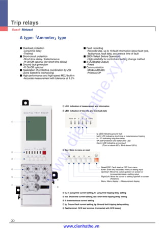
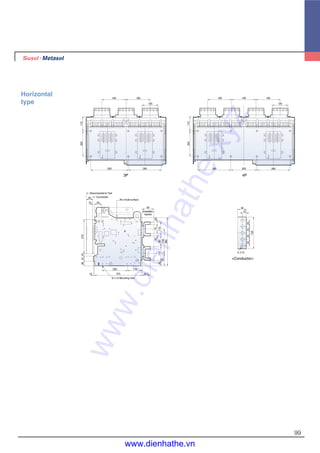
![15
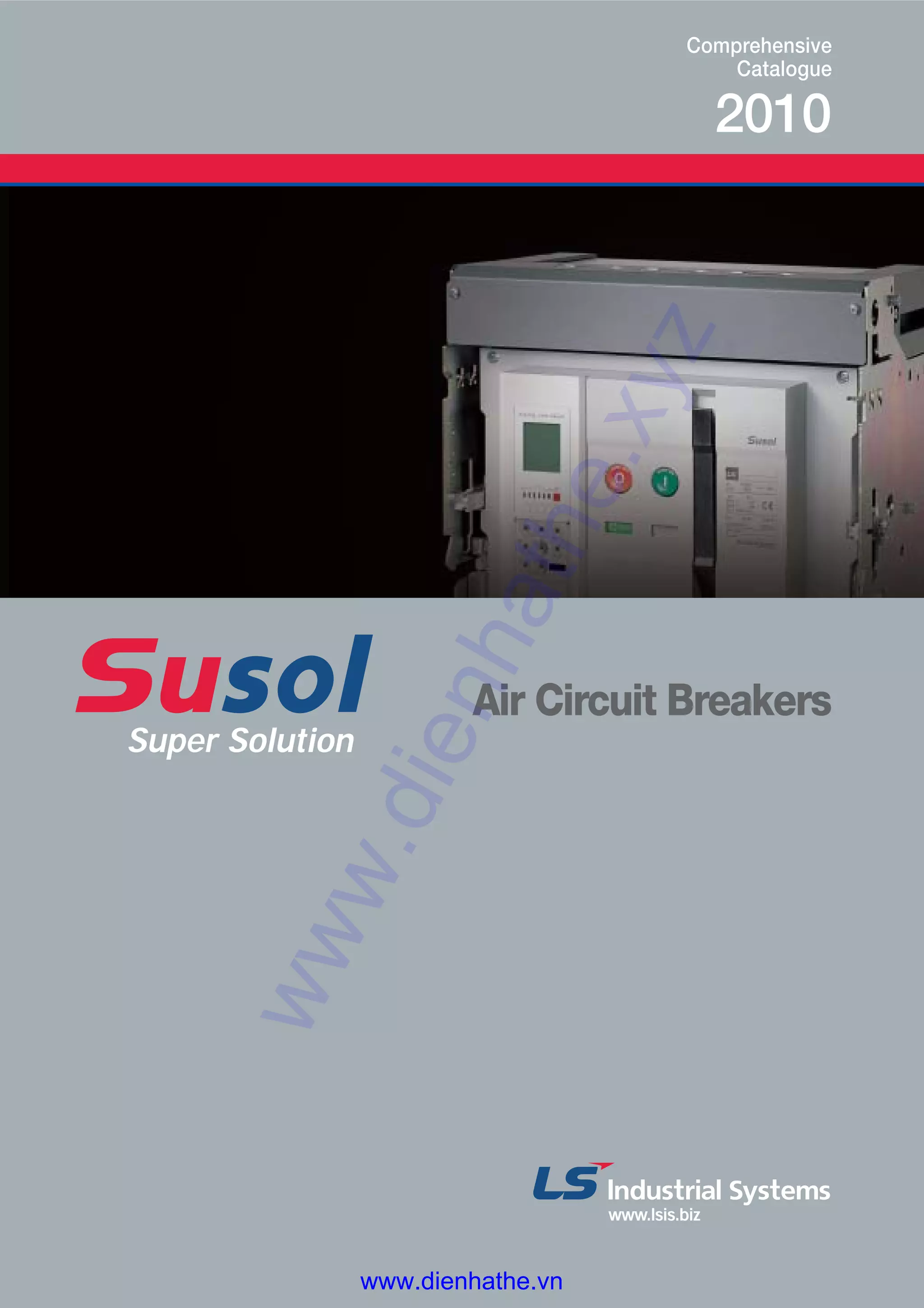
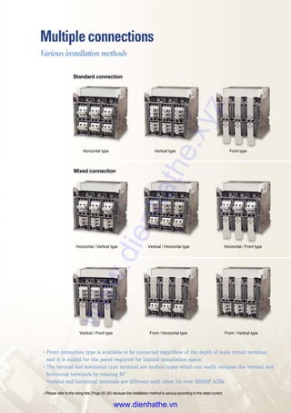
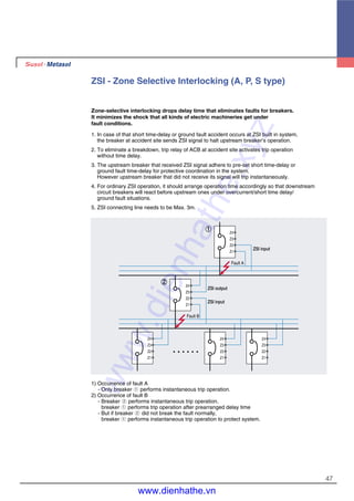
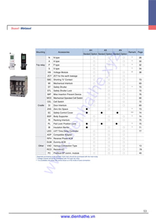
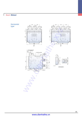
Terms
�Terminal cover of control circuit
�Cradle finger (Line side)
�Cradle finger (Load side)
�Draw-out handle
�Position indicator
�Handle storage space
�Pad lock button
�Connecting conductor (Line side)
�Connecting conductor (Load side)
Cradle (Internal) Cradle (Rear)
�
�
�
�
�
�
�
�
�
�Ui: Rated insulation voltage
�Uimp: Impulse withstand voltage
�Ue: Rated operational voltage (AC base)
�Icu: Ultimate breaking capacity
�Ics: Service breaking capacity
�Icw: Short time withstand current
�MFG. Date: Manufacturing date
[Acronym explanation]
Explanation of terminologies
�Motor charge
�Closing coil
�Shunt tripping coil
�Auxiliary switches: Contact specification
and terminal No.
�Under voltage trip: UVT terminal No.
�OCR control source: Trip relay control power
�Alarm switch: Alarm and terminal No.
�Digital trip relay: Switching diagram
�Z.S.I: Input/Output terminal No.
�Reset: LED/LCD reset
�Communication: Communication and
terminal No.
�Voltage module: Phase voltage and symbol
�Earth/Leakage: Ground fault / Earth
leakage input terminal No.
Control power and
terminal No.
[Secondary nameplate]
Main nameplate
www.dienhathe.xyz
www.dienhathe.vn](https://image.slidesharecdn.com/cataloglssusolacbdenhathe-171218093401/85/Catalog-ls-susol-acb_denhathe-vn-15-320.jpg)

![39
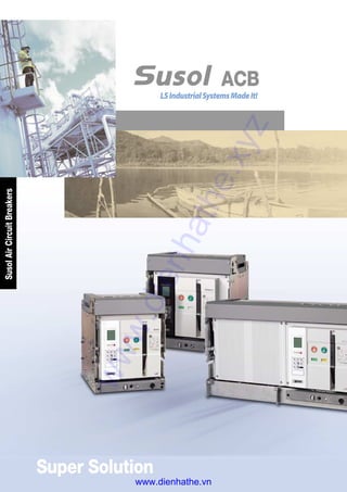
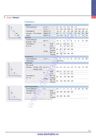
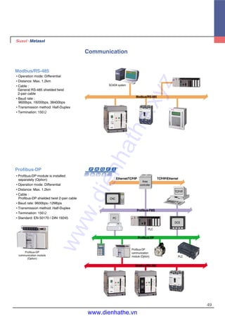
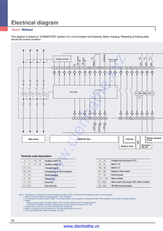
Man machine interface
1. H/W set
7. DO Setup
1. Wiring
2. Comm
3. Password
4. Time-RTC
5. Demand
6. Data Rst
Run Time
Max Power
Demand
Energy
CB Count
2. Relay set
6. OFR/UFR
1. OCR
2. OCGR
3. OVR/UVR
4. Unbal
5. rPower
4. Clear All
1. Event
2. Clear All
3. Fault
4. Sys info 5. L/R (L)
Initial display
M
3. Events
Setting display
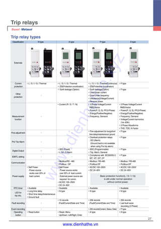
Measurement display
An example of graphic LCD display
Initial display
Initial display
Displayed screen when changing
Ir value into 1.0
(After 3 sec, return to initial display)
tg adjustment
knob
Displayed screen when changing
tg value into 0.2
(After 3sec, return to initial display)
1000 A
R S T N
100%
50%
Ir =
1000 A
Tg =
200 ms
[I2T Off]
1000 A
R S T N
100%
50%
.4
.3
.2
.4
.3
.2
.1
.1 .05
tg
(S)
on
I2
toff
.7
.6
.5
.8
.9
1
.4
Ir
×In
1000 A
R S T N
100%
50%
Ir adjustment
knob
www.dienhathe.xyz
www.dienhathe.vn](https://image.slidesharecdn.com/cataloglssusolacbdenhathe-171218093401/85/Catalog-ls-susol-acb_denhathe-vn-39-320.jpg)
![40
PASSWORD 1.OCR
2.OCGR
3.OVR/UVR
4.Unbal
5.rP/OPR
1000 A
R S T N
100%
50%
1.H/W Set
2.Relay Set
3.Events
4.Sys Info
5.L/R [L]
1.H/W Set
2.Relay Set
3.Events
4.Sys Info
5.L/R [L]
M
XXXX
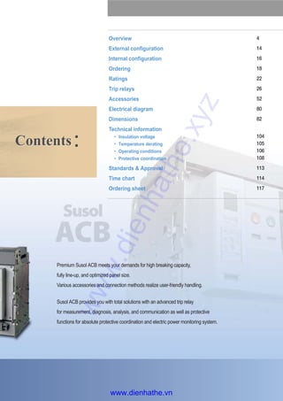
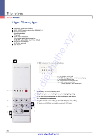
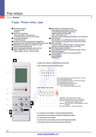
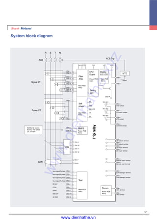
Trip relays
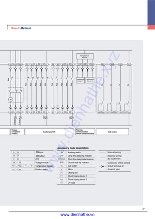
Protection element setting
Initial display
Relay setting display
Setting display
Password input
Find adjustment of protection setting current
�OCR and OCGR's current
setting is basically controlled by
knob's setting values.
�The fine current that cannot
be controlled by knob is
adjustable by using , key.
�Fine adjustment is only
adjustable in the present knob
and next knob's setting range,
when moving knob, the
adjusted data becomes reset
state.
�The setting method of OCGR
is same with OCR's, fine
adjustment is available.
OCR-L, S, I
800 A
EIT
6400 A
15000 A
I2T
[Off]
OCR-L, S, I
800 A
EIT
6400 A
15000 A
I2T
[Off]
OCR-L, S, I
I2T
[Off]
OCR-L, S, I
I2T
[Off]
800 A
EIT
6400 A
15000 A
800 A
EIT
6401 A
15000 A
1.OCR
2.OCGR
3.OVR/UVR
4.Unbal
5.rP/OPR
�
OVR/UVR Set
Pick Up : 724 V
Delay : 1.2 s
Action : None
Pick Up : 150 V
Delay : 1.2 s
Action : D01
1.OCR
2.OCGR
3.OVR/UVR
4.Unbal
5.rP/OPR
�
Unbal V/I
Pick Up : 6 %
Delay : 10.0 s
Action : D02
Pick Up : 12 %
Delay : 10.0 s
Action : D03
6.OFR/UFR
�
OFR/UFR Set
Pick Up : 65 Hz
Delay : 10.0 s
Action : D01
Pick Up : 55 Hz
Delay : 10.0 s
Action : None
1.OCR
2.OCGR
3.OVR/UVR
4.Unbal
5.rP/OPR
�
rPower
Pick Up :100 kW
Delay : 10.0 s
Action : D02
Pick Up : 2400 kW
Delay : 0.2 s
Action : TRIP
Protection setting display OVR/UVR setting Relay setting display Unbalance setting
Relay setting display Reverse power setting Relay setting display Frequency setting
Find adjustment of long-time delay
Select one IDTM characteristic
curve among DT, SIT, VIT and EIT
Find adjustment of short-time delay
Find adjustment of Instantaneous
www.dienhathe.xyz
www.dienhathe.vn](https://image.slidesharecdn.com/cataloglssusolacbdenhathe-171218093401/85/Catalog-ls-susol-acb_denhathe-vn-40-320.jpg)
![41
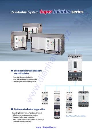
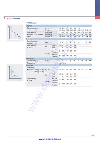
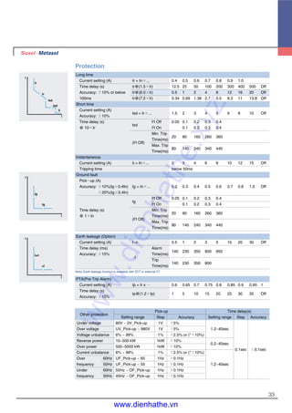
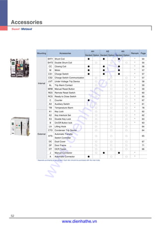
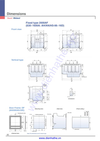
Measurement element display
1000 A
R S T N
100%
50%
VR 220 V∠0.0
IR 1000 A∠330.0
P 986 kW
Q 589 kVar
PF 0.866 F 60.0
EP 56 kWh
EQ 32 kVarh
Metering Overview
VR : 220∠ 0.0
VS : 220∠240.0
VT : 220∠120.0
CURRENT [A]
IR : 1000∠330.0
IS : 1000∠210.0
IT : 1000∠ 90.0
IN : 0
VOLTGAE [V]
R : 1000
S : 1000
T : 1000
Max Demand [kW]
986
2007/05/14
11:15:00
Demand Current [A]
987
2007/05/14
10:00:00
Max Power [kW]
Vector Diagram
Vr
Ir
Vs
Is
Vt It
Vpos : 220 V
Vneg : 0 V
Unbal: 0.0 %
V unbal 3Phase
I unbal 3Phase
Ipos : 1000 A
Ineg : 0 A
Unbal: 0.0 %
Power Diagram
P=986
Q=589
R : 328 Total
S : 328 986
T : 328
Reactive [kVar]
R : 189 Total
S : 189 589
T : 189
Active Power [kW]
R : 360 Total
S : 360 1080
T : 360
Forward Q [kVarh]
R : 210 Total
S : 210 630
T : 210
Forward P [kWh]
R : 0 Total
S : 0 0
T : 0
Reverse Q [kVarh]
R : 0 Total
S : 0 0
T : 0
Reverse P [kWh]
R : 0.1 %
S : 0.1 %
T : 0.1 %
Current K - Factor
R : 1.2
S : 1.2
T : 1.3
TDD 3Phase
R : 379 Total
S : 379 1139
T : 379
Power Factor
R : 0.87 Total
S : 0.87 0.866
T : 0.87
Apparent [kVA]
P+ 1051 kWh
Q+
607 kVarh
Forward Energy
P- 0 kWh
Q- 0 kVarh
Reverse Energy
Volt Wave & FFT [%]
THD[S] : 25.0
Curr Wave & FFT [%]
THD[R] : 3.0 H1 1000 H8 0
H2 0 H9 3
H3 15 H10 0
H4 0 H11 1
H5 20 H12 0
H6 0 H13 1
H7 0 H14 0
R Curr Harmonics [A]
H1 220 H8 0
H2 0 H9 0
H3 55 H10 0
H4 0 H11 0
H5 0 H12 0
H6 0 H13 0
H7 0 H14 0
S Volt Harmonics [V]
H15 0 H22 0
H16 0 H23 0
H17 55 H24 0
H18 0 H25 0
H19 0 H26 0
H20 0 H27 0
H21 0 H28 0
S Volt Harmonics [V]
H15 1 H22 0
H16 0 H23 1
H17 1 H24 0
H18 0 H25 1
H19 1 H26 0
H20 0 H27 1
H21 1 H28 0
R Curr Harmonics [A]
H57 0
H58 0
H59 0
H60 0
H61 0
H62 0
H63 0
S Volt Harmonics [V]
H57 0
H58 0
H59 0
H60 0
H61 0
H62 0
H63 0
R Curr Harmonics [A]
� �
� �
� �
� �
� �
� �
kW
1000
R
S
I
R
S
T
kVar 2000
Load current
Measurement
overview
Voltage/Current
vector diagram
Voltage/Current
harmonics
(S type)
Power and
power factor
Energy
www.dienhathe.xyz
www.dienhathe.vn](https://image.slidesharecdn.com/cataloglssusolacbdenhathe-171218093401/85/Catalog-ls-susol-acb_denhathe-vn-41-320.jpg)

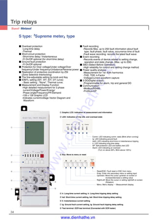
![Trip relays
48
Remote reset and digital I/O (A, P, S type)
In case of that ACB operates due to accidents or over current,
Trip relay indicates the information of the accident through the LED and LCD.
Trip relay A, P and S type is possible to perform the remote reset by digital input,
and have 3 DO(Digital output).
1. Methods to reset Trip relay is to push the Reset button on the frontal side and to
use the remote reset.
2. Digital input
- [R11-R22] input: Remote reset
- [Z1-Z2] Input: ZSI input
- [E1-E2] Input: ZCT for earth leakage detection or external CT input
※All DI are dry contact that has 3.3V of recognition voltage. When inputting close by
SSR(Solid State Relay) or open-collector, connect collector(Drain) to R11.
3. Digital output 3a(524, 534, 544-513)
- Fault output: Long/Short time delay, Instantaneous, Ground fault, UVR, OVR, UFR,
OFR, rPower, Vunbal, Iunbal
(Maintains state as Latch form until user pushes reset.)
- General DO: when setting L/R as remote, it is available to control close/open
remotely by using communication.
E1V1 V2 V3
Trip relay
Vn
Voltage module
Z3 Z1
Z4 Z2
485+
485-
R11
544
R22
534 524
R2 R1
Power supply
ZSIoutput
ZSIinput
ZCT
Common
Reset
LTD
S/I
GTD
513
Trip Digital Long Short Instantaneous Ground
Overload
OVR UVR rPower Vunbal Iunbal OFR UFR OPR Note
Relay Output time time Alarm
P, S
DO1(524) ● ○ ○ ○ ○ ○ ○ ○ ○ ○ ○ ○ ○
type
DO2(534) ○ ● ● ○ ○ ○ ○ ○ ○ ○ ○ ○ ○ Programmable
DO3(544) ○ ○ ○ ● ○ ○ ○ ○ ○ ○ ○ ○ ○
DO1(524) ● × × ×
A type DO2(534) × ● ● × Not available Fixed
DO3(544) × × × ●
www.dienhathe.xyz
www.dienhathe.vn](https://image.slidesharecdn.com/cataloglssusolacbdenhathe-171218093401/85/Catalog-ls-susol-acb_denhathe-vn-48-320.jpg)
![Trip relays
50
Event & fault recording (P, S type)
When there are events such as setting change, Info. change, error of self-diagnose,
state change, P and S type record Max. up to 256 information of the events in accordance with
time(ms). In addition, they can record Max. up to 256(up to 10 for A type) information of the faults
such as fault cause, fault phase, fault value and so on in accordance with time(ms).
Event information display
Initial display Setting display
Password
input
1000 A
R S T N
100%
50%
1.H/W Set
2.Relay Set
3.Events
4.Sys Info
5.L/R [L]
1.Event
2.Clear All
3.Fault
4.Clear All
M
1. Event-L
2007/05/15
20:29:41
Sta Change
Power On
10.Event-L
2007/04/15
10:11:24
Cfg Change
Comm Set up
Fault information display
Initial display Setting display
Password
input
1000 A
R S T N
100%
50%
1.H/W Set
2.Relay Set
3.Events
4.Sys Info
5.L/R [L]
1.Event
2.Clear All
3.Fault
4.Clear All
M
1. Trip
2007/04/26
08:35:52
OCR-Short
PhaseT 930A
9. Trip
2007/04/11
09:11:32
UVR
Phase R OV
System information
P and S type can indicate information as followings with the information of the ACB.
- Present time: year/month/date/hour/minute/ms
- ACB current ratings
- N-phase current ratings: 100%
- Frequency information: 60Hz / 50Hz
- Closing numbers of breaker: CB ON numbers
- Trip relay operating time: OCR ON time
- ON time of breaker: CB ON time
- S/W ver. information
System information display
Initial display Setting display
Password
input
1000 A
R S T N
100%
50%
1.H/W Set
2.Relay Set
3.Events
4.Sys Info
5.L/R [L]
M System Info
DateTime
2007/05/15 21:23:30
Rating 1000 A
Ex-Func 4POCGR
Freq 60 Hz
CB ON# 23
Ver-Arm 1.41
System Info
DateTime
2007/05/15 21:23:30
Rating 1000 A
Ex-Func 4POCGR
T-OPER 220 h
T-CB ON 180 h
Ver-Msp 1.01
www.dienhathe.xyz
www.dienhathe.vn](https://image.slidesharecdn.com/cataloglssusolacbdenhathe-171218093401/85/Catalog-ls-susol-acb_denhathe-vn-50-320.jpg)
![Accessories
54
Shunt Coil [SHT1]
�SHT1 is a control device which trips a
circuit breaker from remote place, when
applying voltage continuously or
instantaneously over 200ms to coil
terminals(C1, C2).
�When UVT coil is installed, its location
is changed.
1. Rated voltage and characteristics of Trip coil
Rated voltage [Vn] Power consumption (VA or W)
DC [V] AC [V]
Operating voltage range [V]
Inrush Steady-state
Trip time [ms]
24~30 - 0.6~1.1 Vn
48~60 48 0.6~1.1 Vn Less
100~130 100~130 0.56~1.1 Vn 200 5 than
200~250 200~250 0.56~1.1 Vn 40ms
- 380~480 0.56~1.1 Vn
Note) Operating voltage range is the min. rated voltage standard for each rated voltage(Vn).
2. Specification of the wire
�Refer to the below table regarding the length and specification of wire when using trip coil with
DC 24~30[V] or DC/AC 48~60[V] of rated voltage.
Shunt coil 1
The maximum wire length
Rated voltage [Vn]
DC 24~30 [V] DC/AC 48 [V]
Wire type
#14 AWG #16 AWG #14 AWG #16 AWG
(2.08mm2
) (1.31mm2
) (2.08mm2
) (1.31mm2
)
Operating 100% 95.7m 61m 457.8m 287.7m
voltage 85% 62.5m 38.4m 291.7m 183.2m
Opening
order
C1
C2
SHT1
Wiring Diagram
* 점선은 User 배선임
Opening
order
C1
C2
SHT1
Wiring Diagram
* The dotted line to
be made by the
customer
www.dienhathe.xyz
www.dienhathe.vn](https://image.slidesharecdn.com/cataloglssusolacbdenhathe-171218093401/85/Catalog-ls-susol-acb_denhathe-vn-54-320.jpg)
![Opening
order
C11
C12
SHT2
55
Double Shunt Coil [SHT2]
�SHT2 is a control device which trips a
circuit breaker doubly from the outside.
When SHT1 doesn’t operate normally, it
can trip a circuit breaker safely.
�Shunt coil 1: Install it at existing
location.
�Shunt coil 2: Install it on the right side of
the Shunt coil 1
�It is not available with UVT coil when
installing double shunt coil.
1. Rated voltage and characteristics of Trip coil
Rated voltage [Vn] Power consumption (VA or W)
DC [V] AC [V]
Operating voltage range [V]
Inrush Steady-state
Trip time [ms]
24~30 - 0.6~1.1 Vn
48~60 48 0.6~1.1 Vn Less
100~130 100~130 0.56~1.1 Vn 200 5 than
200~250 200~250 0.56~1.1 Vn 40ms
- 380~480 0.56~1.1 Vn
Note) Operating voltage range is the min. rated voltage standard for each rated voltage(Vn).
2. Specification of the wire
�Refer to the below table regarding the length and specification of wire when using trip coil with
DC 24~30[V] or DC/AC 48~60[V] of rated voltage.
Shunt coil 2
The maximum wire length
Rated voltage [Vn]
DC 24~30 [V] DC/AC 48 [V]
Wire type
#14 AWG #16 AWG #14 AWG #16 AWG
(2.08mm2
) (1.31mm2
) (2.08mm2
) (1.31mm2
)
Operating 100% 95.7m 61m 457.8m 287.7m
voltage 85% 62.5m 38.4m 291.7m 183.2m
Wiring Diagram
* The dotted line to
be made by the
customer
Shunt coil 1www.dienhathe.xyz
www.dienhathe.vn](https://image.slidesharecdn.com/cataloglssusolacbdenhathe-171218093401/85/Catalog-ls-susol-acb_denhathe-vn-55-320.jpg)
![Accessories
56
Closing Coil [CC]
�It is a control device which closes a
circuit breaker, when the voltage is
applied continuously or instantaneously
over 200ms to the coil terminals
(A1, A2).
1. Rated voltage and characteristics of Closing coil
Rated voltage [Vn] Power consumption (VA or W)
Shunt time
DC [V] AC [V]
Operating voltage range [V]
Inrush Steady-state [ms]
24~30 - 0.75~1.1 Vn
48~60 48 0.75~1.1 Vn Less
100~130 100~130 0.75~1.1 Vn 200 5 than
200~250 200~250 0.75~1.1 Vn 80ms
- 380~480 0.75~1.1 Vn
Note) Operating voltage range is the min. rated standard for each rated voltage (Vh).
2. Specification of the wire
�Refer to the below table regarding the length and specification of wire when using trip coil with
DC 24~30[V] or DC/AC 48~60[V] of rated voltage.
Closing coil
The maximum wire length
Rated voltage [Vn]
DC 24~30 [V] DC/AC 48 [V]
Wire type
#14 AWG #16 AWG #14 AWG #16 AWG
(2.08mm2
) (1.31mm2
) (2.08mm2
) (1.31mm2
)
Operating 100% 95.7m 61m 457.8m 287.7m
voltage 85% 62.5m 38.4m 291.7m 183.2m
Closing
order
A1
A2
CC
Wiring Diagram
* The dotted line to
be made by the
customer
www.dienhathe.xyz
www.dienhathe.vn](https://image.slidesharecdn.com/cataloglssusolacbdenhathe-171218093401/85/Catalog-ls-susol-acb_denhathe-vn-56-320.jpg)
![57
�Charge the closing spring of a
circuit breaker by the external power
source. Without the external power
source, charge manually.
�Operating voltage range(IEC 60947)
85%~110%Vn
Motor [M]
Input voltage(V) DC 24~30V AC/DC 48~60V AC/DC 100~130V AC/DC 200~250V AC 380V AC 440~480V
Load current(max.) 5A 3A 1A 0.5A 0.3A 0.3A
Starting current(Max.) 5 times of load current
Load rpm(Motor) 15000 ~ 19000 rpm
Charge time Less than 5sec.
Dielectric strength 2kV/min
Using temperature range -20。~ 60。
Using humidity range Max. RH 80% (No dew condensation)
Endurance 15,000 cycle (Load connection, 2 times/min)
Charge switch 10A at 250VAC
Motor
Main
axis
Charge switch
Fully charged
contact
Gear
�It is a built-in contact which sends the signal to the outside, when motor charging is
completed. (2a)
�It has a “1a” contact for communication and the other “1a” contact for complete charging.
�When using an extra communication module (Remote I/O), the state of contacts
can be displayed through the network.
�10A at 250VAC
Charge Switch [CS1]
Charge Switch Communication [CS2]
www.dienhathe.xyz
www.dienhathe.vn](https://image.slidesharecdn.com/cataloglssusolacbdenhathe-171218093401/85/Catalog-ls-susol-acb_denhathe-vn-57-320.jpg)
![Accessories
58
Under Voltage Trip device [UVT]
�If the voltage of the main or the control
power is under voltage, UVT which is
installed inside of the breaker breaks
the circuit automatically.
Please connect with UVT time-delay
device in order to present the time-
delay function because UVT is
technically instantaneous type.
�The closing of a circuit breaker is
impossible mechanically or electrically if
control power not supplied to UVT.
To close the circuit breaker, 65~85% of
rated voltage should be applied to both
terminals of UVT coil (D1, D2).
�When using UVT coil, the double trip
coil can not be used, and the location of
trip coil is changed.
1. Rated voltage and characteristics of UVT coil
Rated voltage [Vn] Operating voltage range [V] Power consumption (VA or W)
DC [V] AC [V] Pick up Drop out Inrush Steady-state
Trip time [ms]
24~30 -
48~60 48 Less
100~130 100~130 0.65~0.85 Vn 0.4~0.6 Vn 200 5 than
200~250 200~250 50ms
- 380~480
Note) Operating voltage range is the min. rated standard for each rated voltage (Vh).
2. Specification of the wire
�Refer to the below table regarding the length and specification of wire when using trip coil with
DC 24~30[V] or DC/AC 48~60[V] of rated voltage.
UVT coil Shunt coil
Closing
coil
The maximum wire length
Rated voltage [Vn]
DC 24~30 [V] DC/AC 48 [V]
Wire type
#14 AWG #16 AWG #14 AWG #16 AWG
(2.08mm2
) (1.31mm2
) (2.08mm2
) (1.31mm2
)
Operating 100% 48.5m 30.5m 233.2m 143.9m
voltage 85% 13.4m 8.8m 62.5m 39.3m
Note) In case of using UVT coil, the location of TC coil is changed.
www.dienhathe.xyz
www.dienhathe.vn](https://image.slidesharecdn.com/cataloglssusolacbdenhathe-171218093401/85/Catalog-ls-susol-acb_denhathe-vn-58-320.jpg)
![59
Trip Alarm Contact [AL]
�When a circuit breaker is tripped by OCR which operates against the fault current
(Over Current Relay), Trip Alarm switch provides the information regarding the trip of circuit
breaker by sending the electrical signal from the mechanical indicator on main cover of main
circuit breaker or internal auxiliary switch. (Installed at the inside of circuit breaker)
�When a circuit breaker tripped by fault current, a mechanical trip indicator
(MRB, Manual Reset Button) pops out from the main cover and the switch (AL) which sends
control signal electrically is conducted to output the information occurred from fault circuit
breaker.
�MRB and AL can be operated only when tripping by OCR,
but doesn’t be operated by Off button and OFF operation of trip coil.
�To re-close a circuit breaker after a trip, press MRB to reset it for closing.
�2pcs of electrical trip switch (AL1, AL2, 1a) are provided (Option)
�Trip alarm contact and MRB(Manual reset bottom) need to be purchased together.
1. Electrical characteristics of trip alarm contact
Rated voltage [V]
Non-inductive load (A) Inductive load (A)
Inrush current
Resistive load lamp load Inductive load(A) Motor load
8V DC 11 3 6 3
30V DC 10 3 6 3
125V DC 0.6 0.1 0.6 0.1 MAX. 24A
250V DC 0.3 0.05 0.3 0.05
250V AC 11 1.5 6 2
AL2, 1a
AL1, 1a
�It is a function which resets a circuit
breaker manually when a circuit breaker is tripped by OCR.
�When a circuit breaker tripped by fault current, a mechanical trip indicator (MRB, Manual Reset
Button) pops out from the main cover and the switch(SDE) which sends control signal electrically
is conducted to output the information occurred from fault circuit breaker.
�MRB can be operated only by OCR but not by OFF operation of circuit breaker. To re-close a
circuit breaker after a trip, press MRB to reset it for closing.
Manual Reset Button [MRB]
MRB reset lever
Manual reset button
Manual reset button
Note) The manual reset button is protruded in the event of trip.
www.dienhathe.xyz
www.dienhathe.vn](https://image.slidesharecdn.com/cataloglssusolacbdenhathe-171218093401/85/Catalog-ls-susol-acb_denhathe-vn-59-320.jpg)
![Accessories
60
Ready to Close Switch [RCS]
�It interlocks with mechanism of circuit
breaker.
�It indicates the status that the circuit
breaker is ready to do closing operation.
�When mechanism is in OFF position or
in Charge, contact is output with “ON”
and it indicates that mechanism can be
closed.
1. Rated voltage and rated current of RES
Rated voltage Operating current(Max.) Operating time Wire spec.
AC/DC 100~130V
AC 6A
#14 AWG (2.08 mm2
)
DC 5A
Less 40ms
AC/DC 200~250V
AC 3A
#16 AWG (1.31 mm2
)
DC 2.5A
Reset
order
183
184
RES
Wiring Diagram
Connect to
AL2 / RES
Connect to inner
micro switch
Remote Reset Switch [RES]
�Following tripping, this function resets the "fault trip" alarm contacts(AL) and the mechanical
indicator(MRB) and enables circuit breaker closing.
Push button switch : AC 125V 10A, AC 250V 6A, DC 110V 2.2A, DC 220V 1.1A Resistive load
�In case of auto reset type circuit breaker
Following tripping, a reset of Manual Reset Button(MRB) or Remote Reset Switch(RES) is
no longer required to enable circuit breaker closing.
The mechanical indicator(MRB) and electrical indicator(AL) remain in fault position until the reset
button is pressed.
�AL2 and RES are alternative.
* The dotted line to
be made by the
customer
Ready to
close switch
“A” contact
Contact part
www.dienhathe.xyz
www.dienhathe.vn](https://image.slidesharecdn.com/cataloglssusolacbdenhathe-171218093401/85/Catalog-ls-susol-acb_denhathe-vn-60-320.jpg)
![61
Auxiliary switch [AX]
�It is a contact used to monitor
ON/OFF position of ACB from
remote place.
Standard classification
Classification
Standard High capacity
Remark
Resistive load Inductive load Resistive load Inductive load
490V 5A 6A 5A 2.5A
AC 250V 10A 6A 10A 10A
Contact 125V 10A 6A 10A 10A
capacity 250V 0.3A 0.3A 3A 1.5A
DC 125V 0.5A 0.6A 10A 6A
30V 10A 6A 10A 10A
AX 3a3b -
BX 5a5b -
HX - 5a5b
AC 3a3b -
BC 5a5b -
CC 6a6b -
HC - 5a5b
JC - 6a6b
No. of Contact
that can be used
Standard
charging
type
Rapid auto-
reclosing
charging type
Standard High capacity
2000, 5000AF 4000, 6300AF 2000, 5000AF 4000, 6300AF
AUX. contact & charging types
AX Standard OFF charge 3a3b
AC Standard ON charge 3a3b
BX Standard OFF charge 5a5b
BC Standard ON charge 5a5b
HX High capacity OFF charge 5a5b
HC High capacity ON charge 5a5b
CC Standard ON charge 6a6b
JC High capacity ON Charge 6a6b
Standard High capacity
www.dienhathe.xyz
www.dienhathe.vn](https://image.slidesharecdn.com/cataloglssusolacbdenhathe-171218093401/85/Catalog-ls-susol-acb_denhathe-vn-61-320.jpg)
![Accessories
62
Key Interlock Set [K2]
�3 circuit breakers can be arranged for the continuous
power supply to the load side and be interlocked
mutually by using Key Lock embedded in each circuit
breaker.
ACB1
Load 1 Load 2
ACB2
ACB3
ACB-1 ACB-2 ACB-3
Status
LOAD1 LOAD2
● ● ● OFF OFF
● ○ ○ ON ON
○ ● ○ ON ON
○ ○ ● ON ON
● ● ○ OFF OFF
● ○ ● OFF ON
○ ● ● ON OFF
Wiring
Key Lock [K1]
�It is a device for locking which
prevents a certain circuit breaker from
being operated by user‘s discretion
when two or more circuit breakers are
used at the same time.
�K1: Preventing mechanical closing
K1
○: Release ●: Lock
www.dienhathe.xyz
www.dienhathe.vn](https://image.slidesharecdn.com/cataloglssusolacbdenhathe-171218093401/85/Catalog-ls-susol-acb_denhathe-vn-62-320.jpg)
![63
Double Key Lock [K3]
�When only two keys are released at the
same time, circuit breakers operate.
Handling method is same as K1.
Key interlock double
ON/OFF Button Lock [B]
�It is to prevent manual operation of
ACB’s closing/tripping button due to
user’s wrong handling.
�It is not possible to handle ON/OFF
operation under the
“Button lock” status.
Note) Padlocks(∅5 ~ ∅6) are not supplied.
ON/OFF button lock
www.dienhathe.xyz
www.dienhathe.vn](https://image.slidesharecdn.com/cataloglssusolacbdenhathe-171218093401/85/Catalog-ls-susol-acb_denhathe-vn-63-320.jpg)
![Accessories
64
Condenser Trip Device [CTD]
�It gets a circuit breaker tripped
electrically within regular time when
control power supply is broken down and
is used with Shunt coil, SHT. In case
there is no DC power, It can be used as
the rectifier which supplies DC power to
a circuit breaker by rectifying AC power.
Circuit diagram
AC input DC output
External dimension
7.5
15
118
131
75
108
75
Side view
Rear view Front view
Ratings
Specification
CTD-100 CTD-200
AC 100/110 AC 200/220
50/60 50/60
140/155 280/310
Within 5S Within 5S
Over 3 MIN Over 2 MIN
85~110 85~111
400㎌㎌ 160㎌㎌
Ratings
Model
Rated input voltage (V)
Frequency (㎐㎐)
Rated charge voltage (V)
Charging time
Trip possible time
Range of Input voltage (%)
Condenser capacity
Lifting Hook [LH]
�It is a device to
make an ACB easy to shift.
�Please hang it to both handles
of the arc cover.
www.dienhathe.xyz
www.dienhathe.vn](https://image.slidesharecdn.com/cataloglssusolacbdenhathe-171218093401/85/Catalog-ls-susol-acb_denhathe-vn-64-320.jpg)
![65
Automatic Transfer Switch Controller [ATS]
Ratings
Model type ATSC-110 ATSC-220
Rated voltage AC 110V AC 220V
Voltage range AC 93.5(±5%) ~126.5V(±5%) AC 187(±5%) ~ 253V(±5%)
Frequency 50Hz/60Hz
Power consumption (apparent power) 15.4W
4-location switch (stop, N, R, Auto) � �
Test function � �
Generator control function � �
N power source setting (phase-to-phase/ 3phases) � �
Time setting (T1~T6) � �
Fault function (OCR/Circuit breaker trouble) � �
Output contact (Auto, Load burden) � �
Communication function (RS-485) - -
�T1: The delayed time from when UN (power supply of electric company) is tripped to when
generator start-up signal contact is closed. (t1: 0.2, 0.5, 1, 2, 4, 8, 15, 30, 40, 50secs)
�T2: The delayed time from when UN is closed to when ACB2 is tripped.
(t2: 0.2, 1, 2, 4, 8, 15, 30, 60, 120, 240secs)
�T3: The delayed time from when ACB1 is tripped to when ACB2 is closed.
(t3: 0.5, 1, 2, 5, 10, 15, 20, 25, 30, 40secs)
�T4: The delayed time from when ACB2 is tripped to when ACB1 is closed.
(t4: 0.5, 1, 2, 5, 10, 15, 20, 25, 30, 40secs)
�T5: The delayed time when ACB1 is closed to when generator start-up signal contact is
opened. (t5: 60, 120, 180, 240, 300, 360, 420, 480, 540, 600secs)
�Stop-mode: This mode is for compulsory trip of ACB1(electric power company) or
ACB2 (power station) when UN (power supply of electric power company) or UR (power supply
of power station) is available
*UN or UR should be kept in ON position
�N-mode: This mode is for compulsory closing of ACB1 when UN is available.
* it does not matter to be ON or OFF position of UR and if converting to N-mode while using UR,
generator start-up signal contact is opened.
�R-mode: This mode is for compulsory closing of ACB2 during the use of UR regardless of that
UN is available or not.
�Auto-mode: This mode is for transferring a circuit breaker automatically to available power
supply of UN or UR. In short, it trips the circuit breaker where power supply is not available and it
close the circuit breaker where power supply is available.
www.dienhathe.xyz
www.dienhathe.vn](https://image.slidesharecdn.com/cataloglssusolacbdenhathe-171218093401/85/Catalog-ls-susol-acb_denhathe-vn-65-320.jpg)
![Accessories
66
OCR Tester [OT]
Configuration
�It is a device which can test for the
operation of Trip Relay under no power
condition.
1. Maximum 17 times rated current
can be inputted.
2. It is possible to enter the current value
and phase on each of R/S/T/N
3. Frequency is adjustable.
4. It is available to test for long time
delay/short time delay/instantaneous
/ground fault.
OCR tester
R, S, T, N phase signal input
Increase/Decrease signal input
Signal setting/Delete
Waveform generation/Stop
Select frequency
R S T N
ENT. ESC
START STOP
60Hz50Hz
Hz
www.dienhathe.xyz
www.dienhathe.vn](https://image.slidesharecdn.com/cataloglssusolacbdenhathe-171218093401/85/Catalog-ls-susol-acb_denhathe-vn-66-320.jpg)
![67
Dust Cover [DC]
�Attach it to the door frame.
�It protects the product against the dust
(IP5X) which may cause fault operation
and enhances the sealing degree by
being mounted to protrude type of
panel.
�It is transparent so that the front side of
ACB is visible and the Cover can be
opened/closed even if ACB is drawn out
to until TEST position.
Dust cover Door frame
Panel
door
�It displays the total number of ON/OFF
operation of ACB.
Counter [C]
Counter
www.dienhathe.xyz
www.dienhathe.vn](https://image.slidesharecdn.com/cataloglssusolacbdenhathe-171218093401/85/Catalog-ls-susol-acb_denhathe-vn-67-320.jpg)
![Accessories
68
13 23 33 43 53 11 21 31 41 51
52423222125444342414
b2b1
AUX S/W
b3 b4 b5a1 a2 a3 a4 a5
13 23 33 43 53 11 21 31 41 51
52423222125444342414
b2b1
AUX S/W
b3 b4 b5a1 a2 a3 a4 a5
Mechanical Operated Cell Switch [MOC]
�It is the contact (10a10b) which displays the ON/OFF condition of ACB.
It mechanically operates only when the breaker is “CONNECTED” position.
A standard type and a high capacity type is available.
�The contact capacity is as same as the ratings of aux. contacts.
�When MOC link is installed to cradle, MOC can be equipped with the inside of panel.
www.dienhathe.xyz
www.dienhathe.vn](https://image.slidesharecdn.com/cataloglssusolacbdenhathe-171218093401/85/Catalog-ls-susol-acb_denhathe-vn-68-320.jpg)
![69
Mechanical Interlock [MI]
�It is used to interlock closing and trip between two or three breakers mechanically
so as to prevent unintended operation at the same time.
�Wire type interlock can be applied upto 3 breakers
Door Interlock [DI]
�It is a safety device which
does not allow the panel
door to open when a
circuit breaker is in the
“ON” position.
Install on the door of panel
Install on the side plate of
ACB cradle
www.dienhathe.xyz
www.dienhathe.vn](https://image.slidesharecdn.com/cataloglssusolacbdenhathe-171218093401/85/Catalog-ls-susol-acb_denhathe-vn-69-320.jpg)
![Accessories
70
Safety Shutter Lock [STL]
�It is a locking device which prevents
safety shutter from being opened when
it is closed.
→ If shutter lock is connected with
guide shutter, the guide shutter can
not be pushed structurally.
Thus, it is not available to open the
safety shutter.
Key lockShutter lock
Guide shutterShutter plate
Safety Shutter [ST]
�It is the automatic safety device to
protect the connectors of main circuit by
cutting off dangerous contact from
outside while the breaker is drawn out.
When the ACB is drawn in, the shutter
is automatically opened.
�There are 4 types of Safety Shutter and
they are divided as shown in figure
below.
The types of safety shutter plate
2000/5000AF, 3P 4000/6300AF, 3P
2000/5000AF, 4P 4000/6300AF, 4P
Note) Padlocks(∅5 ~ ∅6) are not supplied.
www.dienhathe.xyz
www.dienhathe.vn](https://image.slidesharecdn.com/cataloglssusolacbdenhathe-171218093401/85/Catalog-ls-susol-acb_denhathe-vn-70-320.jpg)
![71
Door Frame [DF]
�When structuring the embedded type of
ACB panel, it protects the protrude front
of ACB and the cutting side of
panel door by attaching it to the panel
door.
Panel doorDoor frame
�Insulation barrier prevents the arc which may arise and result in short-circuit
between phases in advance
�As “C” stands for “CRADLE”, install the insulation barrier in the direction of
“C” in case of Draw-out type.
�As “A” stands for “ACB main frame”, install the insulation barrier in the direction
of “A” in case of Fixed type.
Insulation Barrier [IB]
Draw-out typeFixed type
www.dienhathe.xyz
www.dienhathe.vn](https://image.slidesharecdn.com/cataloglssusolacbdenhathe-171218093401/85/Catalog-ls-susol-acb_denhathe-vn-71-320.jpg)
![Accessories
72
Cell Switch [CEL]
�It is a contact which indicates the
present position of ACB.(CONNECTED,
TEST, DISCONNECTED)
<Contact configuration>
4C: 1Disconnected +1Test +2Connected
8C: 2Disconnected +2Test +4Connected
※ Contact configuration can be changeable if necessary.
ACB position
Draw-in and draw-out position
DISCONNECTED CONNECTED
DISCONNECTED TEST CONNECTED
Contact
operation
Contact
capacity
Contact number 4C
CL-C
(Connected)
CL-T
(Test)
CL-D
(Disconnected)
ON
ON
ON
OFF
OFF
OFF
Voltage(V) Resistive load Inductive load
460V 5 2.5
AC 250V
10 10
125V
250V 3 1.5
DC 125V 10 10
30V 10 10
Cell switch
www.dienhathe.xyz
www.dienhathe.vn](https://image.slidesharecdn.com/cataloglssusolacbdenhathe-171218093401/85/Catalog-ls-susol-acb_denhathe-vn-72-320.jpg)
![73
Zero Arc Space [ZAS]
�Arc which may arise while breaking
fault current is extinguished first by Arc
chute in main body of circuit breaker
and then completely extinguished by
Arc cover.
By preventing arc from exposing to the
outside, it protects itself from all kinds of
accidents.
�It is categorized into 8 types by ratings
and poles.
Ampere frame Cover length (mm)
2000AF 3P 281.4
2000AF 4P 366.4
4000AF 3P 359.4
4000AF 4P 474.4
5000AF 3P 576.4
5000AF 4P 746.4
6300AF 3P 732.4
6300AF 4P 962.4
Arc cover
Shorting “b” Contact [SBC]
�It is the contact which keeps the
external control circuit in normal by Aux.
contact which disconnects “Axb” when
ACB is moved from CONNECTED
position to TEST position. The number
of “shorting b-contact” corresponds to
the number of “Axb” (4b)
Contact condition (Link between Axb and shorting““b””contact)
CLOSE OPEN
Shorting “b” contact
CONNECTED location OFF OFF
TEST location ON ON
Auxiliary contact (Axb)
CONNECTED location OFF ON
TEST location OFF ON
ACB condition
ACB location
Shorting “b”
contactwww.dienhathe.xyz
www.dienhathe.vn](https://image.slidesharecdn.com/cataloglssusolacbdenhathe-171218093401/85/Catalog-ls-susol-acb_denhathe-vn-73-320.jpg)
![Accessories
74
Safety Control Cover [SC]
�It protects control terminals which
exposes to the outside, and prevents
the damages resulted from foreign
substances.
�It is categorized into 8 types by ratings
and poles.
�It protects control terminals which
exposes to the outside, and prevents
the damages resulted from foreign
substances.
�It is categorized into 8 types by ratings
and poles.
�It is available only when the control
block is in the mode of auto-connection.
L
Ampere frame Cover length (mm)
2000AF 3P 334
2000AF 4P 419
4000AF 3P 412
4000AF 4P 527
5000AF 3P 629
5000AF 4P 799
6300AF 3P 785
6300AF 4P 1015
Safety
control
cover
Body Supporter [BSP]
�It interlocks the main body of circuit
breaker and cradle mechanically to fix
the former in connected position.
Therefore, all draw-in/outs are not
available.
Body supporter
www.dienhathe.xyz
www.dienhathe.vn](https://image.slidesharecdn.com/cataloglssusolacbdenhathe-171218093401/85/Catalog-ls-susol-acb_denhathe-vn-74-320.jpg)
![75
Pad Lock / Position Lock [PL]
ACB is subject to restriction regarding moving in connected, test, disconnected when drawing in or
out. If main body of ACB is placed in 3 positions, it is locked and stopped when drawing in or out.
�As shown in the figure, if draw-in/out button pops out, it means locking is operating.
�To continue Draw-in/out operation, release lock by pushing Draw-in/out button
�In case it is locked as shown in the figure above, main body of ACB can not be drawn in or
out into the cradle.
�For the lock device, user has to purchase it. (∅5 ~ ∅6)
Pad lock
Draw-in button
Racking Interlock [RI]
�When panel door is opened, Draw in/out handle doesn’t be inserted.
Thus, panel handle can be inserted only when panel door is closed.
Racking interlockHandle inserting hole
Door plate
www.dienhathe.xyz
www.dienhathe.vn](https://image.slidesharecdn.com/cataloglssusolacbdenhathe-171218093401/85/Catalog-ls-susol-acb_denhathe-vn-75-320.jpg)
![Accessories
76
�When the main body of ACB is inserted to the cradle, if the ratings of ACB does not match with
cradle, it mechanically prevents ACB from being inserted into cradle of ACB.
�The installation method is variable according to ratings.
Miss Insertion Prevent Device [MIP]
B
D
F
A
C
E
G
Cradle
2
4
6
1
3
5
7
ACB body
Cradle ACB Cradle ACB
ABCD 567 ADEF 237
ABCE 467 ADEG 236
ABCF 457 ADFG 235
ABCG 456 AEFG 234
ABDE 367 BCDE 167
ABDF 357 BCDF 157
ABDG 356 BCDG 156
ABEF 347 BCEF 147
Cradle ACB Cradle ACB
ABEG 346 BCEG 146
ABFG 345 BDEF 137
ACDE 267 BDEG 136
ACDF 257 BDFG 135
ACDG 256 CDEF 127
ACEF 247 CDEG 126
ACEG 246 CEFG 124
ACFG 245 DEFG 123
www.dienhathe.xyz
www.dienhathe.vn](https://image.slidesharecdn.com/cataloglssusolacbdenhathe-171218093401/85/Catalog-ls-susol-acb_denhathe-vn-76-320.jpg)
![77
UVT Time Delay Controller [UDC]
�UVT is a device which makes ACB
tripped automatically to prevent the
accident on load side due to under
voltage or power breakdown.
There are two types, Instantaneous
type and time delay type.
�It can be installed on the rail or to the
cradle.
�Instantaneous type: only available with
UVT coil.
�Time delay type: available by
connecting UVT coil and UVT time
delay controller.
�Common use for the all types.
UVT time delay controller
1. The rated voltage and characteristic of UVT time delay controller
2. Wiring
Rated voltage [Vn] Operating voltage range [V] Power consumption (VA or W)
DC [V] AC [V] Pick up Drop out Inrush Steady-state
Trip time[s]
48~60 48
100~130 100~130
0.65~0.85 Vn 0.4~0.6 5Vn 200 5
0.5, 1,
200~250 200~250 1.5, 3
- 380~480
Note) Operating voltage range is the min. rated standard for each rated voltage (Vh).
5
14 16
14
7
16
UVT Time
Delay Controller
Delay trip
Command
Rating voltage
Rating voltage
Instaneous
trip
command
D1
D2
UVT
UVT
18 20
0.5
1.5
1
3
19
75
a
Signal for
tripping
DC48~60V
AC48
[sec]
Time Delay for UVT
bc
www.dienhathe.xyz
www.dienhathe.vn](https://image.slidesharecdn.com/cataloglssusolacbdenhathe-171218093401/85/Catalog-ls-susol-acb_denhathe-vn-77-320.jpg)
![Accessories
78
Control power
AC/DC 110/220V
24V
Relay 3
DO control
RS-485(-)
RS-485(+)
Power
24V GND
5V
5V GND
RS-485
Temperature Alarm(+)
Temperature Alarm(-)
Temp_COM
Temp. Sensor input 4
Temp. Sensor input 3
Temp. Sensor input 2
Temp. Sensor input 1
1
2
8
9
10
11
12
3
4
5
6
7
13
14
15
16
17
18
19
20
MODBUS
Profibus-DP
Temperature Alarm [TM]
�Temperature Alarm Unit is a device to
show the temperature through a
sensor inside of ACB.
�The temperature sensor can be
installed up to 4 and the output is
connected to control terminal blocks.
�It displays the maximum temperature
of them and transmits through a
network.
�If the temperature is higher than a
standard, an alarm can occur.
�Temperature alarm unit
communicates with Modbus /
RS-485 basically, Profibus-DP need
to be purchased separately.
�Temperature alarm unit is installed
on the cradle or the inside of panel.
Temperature
alarm
Temperature alarm
*In case of using
Profibus-DP communication,
it needs to communicate with
ACB trip relay.
*
Temperature LED(℃): 10 ~150℃,
Warning
(Indicates the maximum value)
www.dienhathe.xyz
www.dienhathe.vn](https://image.slidesharecdn.com/cataloglssusolacbdenhathe-171218093401/85/Catalog-ls-susol-acb_denhathe-vn-78-320.jpg)
![79
Remote I/O Unit [RCO]
�Remote I/O unit has the I/O contact which can
trip or close the ACB from the remote site by
communication.
�For the General DO, the output of DI1 or DI2 is
selectable.
�Remote I/O Unit communicates with Modbus /
RS-485 communication basically, Profibus-DP
need to be purchased separately.
�It supports SBO (Select Before Operation)
function and guarantees the control reliability.
�Remote I/O Unit can be installed on the cradle
of ACB or the inside of panel.
- Baud rate setting
- Comm. address setting
- Temperature setting
Control Power
AC/DC 110/220V
24V Relay 0
CB close
Relay 1
CB open
RS-485(-)
RS-485(+)
Power
24V GND
5V
5V GND
RS-485
CB ON
CB OFF
General DI 1
General DI 2
DI_COM
CB ON(+)
CB ON(-)
CB OFF(+)
CB OFF(-)
1
2
3
4
5
6
7
8
9
10
11
12
13
14
15
16
19
20
MODBUS
Profibus-DP
Remote I/O Unit
*In case of using
Profibus-DP communication,
it needs to communicate with
ACB trip relay.
*
LED Status
1 DI1 Indicates digital Input #1condition
2 DI2 Indicates digital Input #2condition
3 DO ON Indicates temperature alarm output is ON
4 DO OFF Indicates temperature alarm output is OFF
5 CB ON Indicates circuit break close condition
6 CB OFF Indicates circuit break open condition
7 RUN LED Indicates unit run condition
8 CB ERROR
Indicates circuit break terminal
Disconnection / control Err condition
Classification Applied range Remarks
CB control
Contact switching capacity AC230V 16A / DC30V 16A
Max. switching capacity 3680VA, 480W
Alarm
Contact switching capacity AC230V 6A / DC25V 6A Induction load
Max. switching capacity 1880VA, 150W (cos∅=0.4, L/R=7ms)
www.dienhathe.xyz
www.dienhathe.vn](https://image.slidesharecdn.com/cataloglssusolacbdenhathe-171218093401/85/Catalog-ls-susol-acb_denhathe-vn-79-320.jpg)
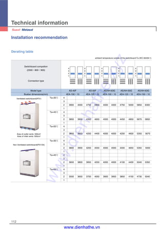
![106
Technical information
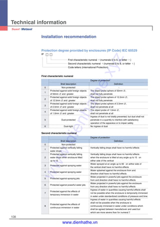
Operating conditions
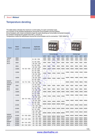
Ambient temperature
ACB devices can operate under the following temperature conditions
- The electrical and mechanical characteristics are stipulated for an ambient temperature of -5°C to +40°C
- The average temperature should be within + 35°C
- Reduce the continuous conducting current when the temperature is over 45°C (refer to temperature derating)
- Storage condition : -20°C to + 60°C is recommended.
Environment
Under clean air;
Maximum temperature + 40°C (relative humidity should be under 85%)
Maximum temperature + 20°C (relative humidity should be under 90%)
Do not apply under corrosive or ammonia gas circumstances
(H2S ≤ 0.01ppm, SO2 ≤ 0.01ppm, NH3 ≤ a few ppm)
* Extreme atmosphere conditions
Under high temperature and/or high humidity, the insulation durability, electrical and
mechanical features could be deteriorated. At this conditions, increasing corrosion-resistant
dealing needs. Corrosion-resistant parts need under this conditions.
Altitude
Susol ACB is designed for operation at altitudes under 2000m. At altitudes higher than 2000m,
emitting heat is lowered and operating voltage, continuous current capacity, and breaking capacity
will be reduced. Durability of the insulation is also reduced according to the atmosphere pressure.
According to the below table, change the ratings upon a service condition.
Altitude [m] 2000m 3000m 4000m 5000mItem
Withstand voltage [V] 3500 3150 2500 2100
Average insulating voltage [v] 1000 900 700 600
Max. using voltage [V] 690 590 520 460
Current compensation constant 1×In 0.99×In 0.96×In 0.94×In
Internal resistance and power consumption (per pole)
630 0.02 24 0.04 48
800 0.02 38 0.04 77
AN-16D 1,000 0.02 60 0.04 120
1,250 0.02 94 0.04 188
1,600 0.02 154 0.04 307
630 0.015 18 0.03 36
800 0.015 29 0.03 58
AH/AS-20D
1,000 0.015 45 0.03 90
1,250 0.015 70 0.03 141
1,600 0.015 115 0.03 230
2,000 0.013 156 0.027 324
2,000 0.01 120 0.02 240
AH/AS-32E 2,500 0.01 188 0.02 375
3,200 0.01 307 0.02 614
2,000 0.01 120 0.02 240
AH/AS-40E
2,500 0.01 188 0.02 375
3,200 0.01 307 0.02 614
4,000 0.008 384 0.011 528
AS-50F
4,000 0.008 384 0.011 528
5,000 0.008 600 0.011 825
4,000 0.006 288 0.009 432
AH/AS-63G 5,000 0.006 450 0.009 675
6,300 0.005 595 0.007 833
AF
Rated current
(A)
Fixed type
Inner resistance
(mΪ)
Power consumption
(W/3Phase)
Inner resistance
(mΪ)
Power consumption
(W/3Phase)
Draw-out type
Note) 1. Above power consumption is whole power consumption for each Rated current, 50/60Hz, 3/4pole. 3. Power factor = 1.0
2. This is inner assistant value per 1 pole.
www.dienhathe.xyz
www.dienhathe.vn](https://image.slidesharecdn.com/cataloglssusolacbdenhathe-171218093401/85/Catalog-ls-susol-acb_denhathe-vn-106-320.jpg)
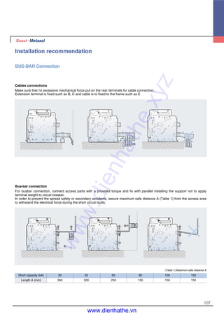
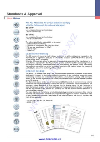
![Rated voltage: AC 220/240V
Main breaker(Main ACB): Susol ACB
Downstream breaker(Downstream MCCB): Susol MCCB TD/TS series
Below protective coordination table is based on ACB equipped with OCR under
arrangement of short time delay trip current as 10 times of rated current.
Note) 1. On table, protective coordination is not available for areas where number is missing.
2. On table, marked number is breaking capacity limit (Unit: kA) for protective coordination.
3. On table, areas that is marked as T are capable of total discrimination up to its Downstream breaker’s rated short breaking capacity.
TD100N 100 85
TD100H 100 100
TD100L 100 200
TD160N 160 85
TD160H 160 100
TD160L 160 200
TS100N 100 100
TS100H 100 120
TS100L 100 200
TS160N 160 100
TS160H 160 120
TS160L 160 200
TS250N 250 100
TS250H 250 120
TS250L 250 200
TS400N 400 100
TS400H 400 120
TS400L 400 200
TS630N 630 100
TS630H 630 120
TS630L 630 200
TS800N 800 100
TS800H 800 120
TS800L 800 200
Susol
MCCB
AH-06D AH-08D AH-10D AH-13D AH-16D AH-20D
200 400 630 400 630 800 1000 1250 1600 2000
3 6 9.45 6 9.45 12 15 18.75 24 30
T T T T T T T T T T
T T T T T T T T T T
T T T T T T T T T T
T T T T T T T T T T
T T T T T T T T T T
T T T T T T T T T T
T T T T T T T T T T
T T T T T T T T T T
T T T T T T T T T T
T T T T T T T T T T
T T T T T T T T T T
T T T T T T T T T T
T T T T T T T T T
T T T T T T T T T
T T T T T T T T T
T T T T T T T
T T T T T T T
T T T T T T T
T T T T T
T T T T T
T T T T T
T T T T
T T T T
T T T T
Susol AH series
AH-D,WProduct typeUpstream
breaker
Rated current [A]
Short time delay
trip current
(Max. 10In)
Is [kA]
Rated current
[A]
Model
Downstream
breaker
Ultimate breaking
capacity Icu [kA] 85
AC 220/240V
AH-D,W
Susol MCCB
Protective coordination
113
www.dienhathe.xyz
www.dienhathe.vn](https://image.slidesharecdn.com/cataloglssusolacbdenhathe-171218093401/85/Catalog-ls-susol-acb_denhathe-vn-113-320.jpg)
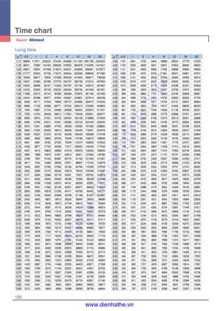
![114
Technical information
Rated voltage: AC 220/240V
Main breaker(Main ACB): Susol ACB
Downstream breaker(Downstream MCCB): Susol MCCB TD/TS series
Below protective coordination table is based on ACB equipped with OCR under
arrangement of short time delay trip current as 10 times of rated current.
Protective coordination
Note) 1. On table, protective coordination is not available for areas where number is missing.
2. On table, marked number is breaking capacity limit (Unit: kA) for protective coordination.
3. On table, areas that is marked as T are capable of total discrimination up to its Downstream breaker’s rated short breaking capacity.
TD100N 100 85
TD100H 100 100
TD100L 100 200
TD160N 160 85
TD160H 160 100
TD160L 160 200
TS100N 100 100
TS100H 100 120
TS100L 100 200
TS160N 160 100
TS160H 160 120
TS160L 160 200
TS250N 250 100
TS250H 250 120
TS250L 250 200
TS400N 400 100
TS400H 400 120
TS400L 400 200
TS630N 630 100
TS630H 630 120
TS630L 630 200
TS800N 800 100
TS800H 800 120
TS800L 800 200
Susol
MCCB
AH-06E AH-08E AH-10E AH-13E AH-16E AH-20E AH-25E AH-32E AH-40E AH-40G AH-50G AH-63G
400 630 800 1000 1250 1600 2000 2500 3200 4000 4000 5000 6300
6 9.45 12 15 18.75 24 30 37.5 48 60 60 75 94.5
T T T T T T T T T T T T T
T T T T T T T T T T T T T
T T T T T T T T T T T T T
T T T T T T T T T T T T T
T T T T T T T T T T T T T
T T T T T T T T T T T T T
T T T T T T T T T T T T T
T T T T T T T T T T T T T
T T T T T T T T T T T T T
T T T T T T T T T T T T T
T T T T T T T T T T T T T
T T T T T T T T T T T T T
T T T T T T T T T T T T T
T T T T T T T T T T T T T
T T T T T T T T T T T T T
T T T T T T T T T T T T
T T T T T T T T T T T T
T T T T T T T T T T T T
T T T T T T T T T T T
T T T T T T T T T T T
T T T T T T T T T T T
T T T T T T T T T T
T T T T T T T T T T
T T T T T T T T T T
Susol AH series
AH-E,X AH-G,Z
Product
type
Upstream
breaker
Rated current [A]
Short time delay
trip current
(Max. 10In)
Is[kA]
Rated
current [A]
Ultimate breaking
capacity Icu [kA]
Model
Downstream
breaker
100 150
AC 220/240V
AH-E,X AH-G,Z
Susol MCCB
www.dienhathe.xyz
www.dienhathe.vn](https://image.slidesharecdn.com/cataloglssusolacbdenhathe-171218093401/85/Catalog-ls-susol-acb_denhathe-vn-114-320.jpg)
![Rated voltage: AC 380/415V
Main breaker(Main ACB): Susol ACB
Downstream breaker(Downstream MCCB): Susol MCCB TD/TS series
Below protective coordination table is based on ACB equipped with OCR under
arrangement of short time delay trip current as 10 times of rated current.
AC 380/415V
AH-D,W
Susol MCCB
Note) 1. On table, protective coordination is not available for areas where number is missing.
2. On table, marked number is breaking capacity limit (Unit: kA) for protective coordination.
3. On table, areas that is marked as T are capable of total discrimination up to its Downstream breaker’s rated short breaking capacity.
TD100N 100 50
TD100H 100 85
TD100L 100 150
TD160N 160 50
TD160H 160 85
TD160L 160 150
TS100N 100 50
TS100H 100 85
TS100L 100 150
TS160N 160 50
TS160H 160 85
TS160L 160 150
TS250N 250 50
TS250H 250 85
TS250L 250 150
TS400N 400 65
TS400H 400 85
TS400L 400 150
TS630N 630 65
TS630H 630 85
TS630L 630 150
TS800N 800 65
TS800H 800 100
TS800L 800 150
Susol
MCCB
AH-06D AH-08D AH-10D AH-13D AH-16D AH-20D
200 400 630 400 630 800 1000 1250 1600 2000
3 6 9.45 6 9.45 12 15 18.75 24 30
T T T T T T T T T T
T T T T T T T T T T
T T T T T T T T T T
T T T T T T T T T T
T T T T T T T T T T
T T T T T T T T T T
T T T T T T T T T T
T T T T T T T T T T
T T T T T T T T T T
T T T T T T T T T T
T T T T T T T T T T
T T T T T T T T T T
T T T T T T T T T
T T T T T T T T T
T T T T T T T T T
T T T T T T T
T T T T T T T
T T T T T T T
T T T T T
T T T T T
T T T T T
T T T T
T T T T
T T T T
Susol AH series
AH-D,WProduct typeUpstream
breaker
Rated current [A]
Short time delay
trip current
(Max. 10In)
Is [kA]
Rated current
[A]
Model
Downstream
breaker
Ultimate breaking
capacity Icu [kA]
85
115
www.dienhathe.xyz
www.dienhathe.vn](https://image.slidesharecdn.com/cataloglssusolacbdenhathe-171218093401/85/Catalog-ls-susol-acb_denhathe-vn-115-320.jpg)
![116
Technical information
Rated voltage: AC 380/415V
Main breaker(Main ACB): Susol ACB
Downstream breaker(Downstream MCCB): Susol MCCB TD/TS series
Below protective coordination table is based on ACB equipped with OCR under
arrangement of short time delay trip current as 10 times of rated current.
AC 380/415V
AH-E,X AH-G,Z
Susol MCCB
Note) 1. On table, protective coordination is not available for areas where number is missing.
2. On table, marked number is breaking capacity limit (Unit: kA) for protective coordination.
3. On table, areas that is marked as T are capable of total discrimination up to its Downstream breaker’s rated short breaking capacity.
TD100N 100 50
TD100H 100 85
TD100L 100 150
TD160N 160 50
TD160H 160 85
TD160L 160 150
TS100N 100 50
TS100H 100 85
TS100L 100 150
TS160N 160 50
TS160H 160 85
TS160L 160 150
TS250N 250 50
TS250H 250 85
TS250L 250 150
TS400N 400 65
TS400H 400 85
TS400L 400 150
TS630N 630 65
TS630H 630 85
TS630L 630 150
TS800N 800 65
TS800H 800 100
TS800L 800 150
Susol
MCCB
AH-06E AH-08E AH-10E AH-13E AH-16E AH-20E AH-25E AH-32E AH-40E AH-40G AH-50G AH-63G
400 630 800 1000 1250 1600 2000 2500 3200 4000 4000 5000 6300
6 9.45 12 15 18.75 24 30 37.5 48 60 60 75 94.5
T T T T T T T T T T T T T
T T T T T T T T T T T T T
T T T T T T T T T T T T T
T T T T T T T T T T T T T
T T T T T T T T T T T T T
T T T T T T T T T T T T T
T T T T T T T T T T T T T
T T T T T T T T T T T T T
T T T T T T T T T T T T T
T T T T T T T T T T T T T
T T T T T T T T T T T T T
T T T T T T T T T T T T T
T T T T T T T T T T T T T
T T T T T T T T T T T T T
T T T T T T T T T T T T T
T T T T T T T T T T T T
T T T T T T T T T T T T
T T T T T T T T T T T T
T T T T T T T T T T T
T T T T T T T T T T T
T T T T T T T T T T T
T T T T T T T T T T
T T T T T T T T T T
T T T T T T T T T T
Susol AH series
AH-E,X AH-G,Z
Product
type
Upstream
breaker
Rated current [A]
Short time delay
trip current
(Max. 10In)
Is[kA]
Rated
current [A]
Ultimate breaking
capacity Icu [kA]
Model
Downstream
breaker
100 150
Protective coordination
www.dienhathe.xyz
www.dienhathe.vn](https://image.slidesharecdn.com/cataloglssusolacbdenhathe-171218093401/85/Catalog-ls-susol-acb_denhathe-vn-116-320.jpg)
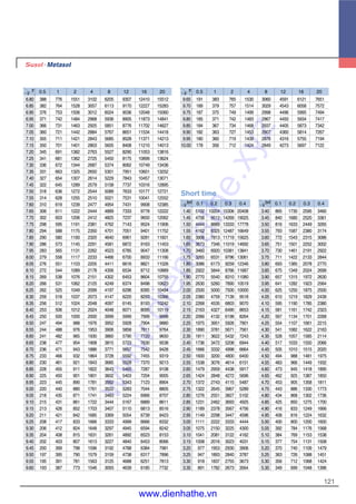
![Rated voltage: AC 480/500V
Main breaker(Main ACB): Susol ACB
Downstream breaker(Downstream MCCB): Susol MCCB TD/TS series
Below protective coordination table is based on ACB equipped with OCR under
arrangement of short time delay trip current as 10 times of rated current.
Note) 1. On table, protective coordination is not available for areas where number is missing.
2. On table, marked number is breaking capacity limit (Unit: kA) for protective coordination.
3. On table, areas that is marked as T are capable of total discrimination up to its Downstream breaker’s rated short breaking capacity.
TD100N 100 30
TD100H 100 50
TD100L 100 65
TD160N 160 30
TD160H 160 50
TD160L 160 65
TS100N 100 42
TS100H 100 65
TS100L 100 85
TS160N 160 42
TS160H 160 65
TS160L 160 85
TS250N 250 42
TS250H 250 65
TS250L 250 85
TS400N 400 42
TS400H 400 65
TS400L 400 85
TS630N 630 42
TS630H 630 65
TS630L 630 85
TS800N 800 42
TS800H 800 85
TS800L 800 100
Susol
MCCB
AH-06D AH-08D AH-10D AH-13D AH-16D AH-20D
200 400 630 400 630 800 1000 1250 1600 2000
3 6 9.45 6 9.45 12 15 18.75 24 30
T T T T T T T T T T
T T T T T T T T T T
T T T T T T T T T T
T T T T T T T T T T
T T T T T T T T T T
T T T T T T T T T T
T T T T T T T T T T
T T T T T T T T T T
T T T T T T T T T T
T T T T T T T T T T
T T T T T T T T T T
T T T T T T T T T T
T T T T T T T T T
T T T T T T T T T
T T T T T T T T T
T T T T T T T
T T T T T T T
T T T T T T T
T T T T T
T T T T T
T T T T T
T T T T
T T T T
T T T T
Susol AH series
AH-D,WProduct typeUpstream
breaker
Rated current [A]
Short time delay
trip current
(Max. 10In)
Is [kA]
Rated current
[A]
Model
Downstream
breaker
Ultimate breaking
capacity Icu [kA]
85
AC 480/500V
AH-D,W
Susol MCCB
117
www.dienhathe.xyz
www.dienhathe.vn](https://image.slidesharecdn.com/cataloglssusolacbdenhathe-171218093401/85/Catalog-ls-susol-acb_denhathe-vn-117-320.jpg)
![118
Technical information
Rated voltage: AC 480/500V
Main breaker(Main ACB): Susol ACB
Downstream breaker(Downstream MCCB): Susol MCCB TD/TS series
Below protective coordination table is based on ACB equipped with OCR under
arrangement of short time delay trip current as 10 times of rated current.
AC 480/500V
AH-E,X AH-G,Z
Susol MCCB
Note) 1. On table, protective coordination is not available for areas where number is missing.
2. On table, marked number is breaking capacity limit (Unit: kA) for protective coordination.
3. On table, areas that is marked as T are capable of total discrimination up to its Downstream breaker’s rated short breaking capacity.
TD100N 100 30
TD100H 100 50
TD100L 100 65
TD160N 160 30
TD160H 160 50
TD160L 160 65
TS100N 100 42
TS100H 100 65
TS100L 100 85
TS160N 160 42
TS160H 160 65
TS160L 160 85
TS250N 250 42
TS250H 250 65
TS250L 250 85
TS400N 400 42
TS400H 400 65
TS400L 400 85
TS630N 630 42
TS630H 630 65
TS630L 630 85
TS800N 800 42
TS800H 800 85
TS800L 800 100
Susol
MCCB
AH-06E AH-08E AH-10E AH-13E AH-16E AH-20E AH-25E AH-32E AH-40E AH-40G AH-50G AH-63G
400 630 800 1000 1250 1600 2000 2500 3200 4000 4000 5000 6300
6 9.45 12 15 18.75 24 30 37.5 48 60 60 75 94.5
T T T T T T T T T T T T T
T T T T T T T T T T T T T
T T T T T T T T T T T T T
T T T T T T T T T T T T T
T T T T T T T T T T T T T
T T T T T T T T T T T T T
T T T T T T T T T T T T T
T T T T T T T T T T T T T
T T T T T T T T T T T T T
T T T T T T T T T T T T T
T T T T T T T T T T T T T
T T T T T T T T T T T T T
T T T T T T T T T T T T T
T T T T T T T T T T T T T
T T T T T T T T T T T T T
T T T T T T T T T T T T
T T T T T T T T T T T T
T T T T T T T T T T T T
T T T T T T T T T T T
T T T T T T T T T T T
T T T T T T T T T T T
T T T T T T T T T T
T T T T T T T T T T
T T T T T T T T T T
Susol AH series
AH-E,X AH-G,Z
Product
type
Upstream
breaker
Rated current [A]
Short time delay
trip current
(Max. 10In)
Is[kA]
Rated
current [A]
Ultimate breaking
capacity Icu [kA]
Model
Downstream
breaker
100 150
www.dienhathe.xyz
www.dienhathe.vn](https://image.slidesharecdn.com/cataloglssusolacbdenhathe-171218093401/85/Catalog-ls-susol-acb_denhathe-vn-118-320.jpg)

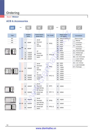
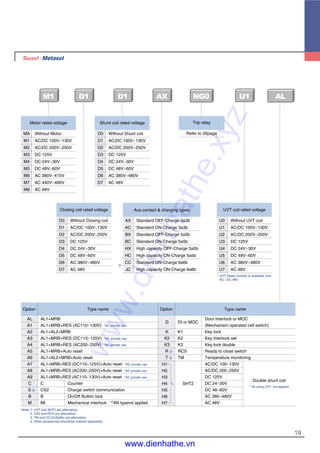
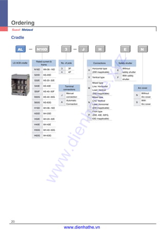
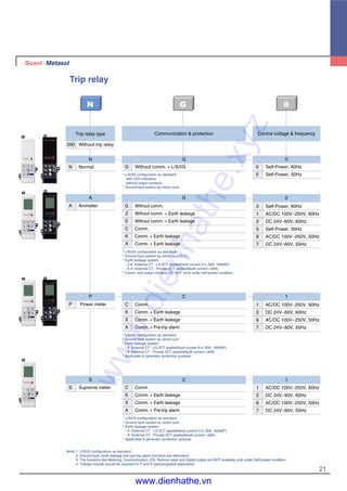
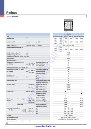
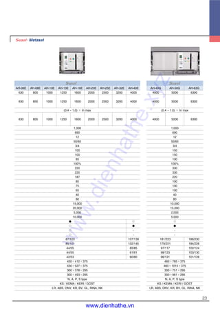
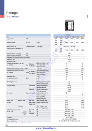
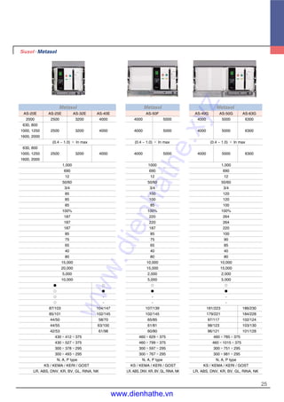
The document provides information on Susol air circuit breakers, including: - Susol ACBs meet demands for high breaking capacity, fully lined-up panels, and optimized sizes. Accessories allow for user-friendly handling. - Susol ACBs provide total solutions with advanced trip relays for measurement, diagnosis, analysis and communication, as well as protective functions. - The document describes technical specifications, components, order information, and accessories of Susol ACBs.


