Downloaded 10 times


![N14
240-600
N12
110-450
N10
85-240
N8
65-185
N7
45-160
N6
45-160
N5
18-105
N3
7-105
5-1N
0.1-18
0N
0.1-13
N2
4-42
SS120
120
SS150
150
SS200
200
SS100
100
SS80
80
SS70
70
SS50
50
SS40
40
SS30
30
SS20
20
SS08
8
SS03
3
SS10
10
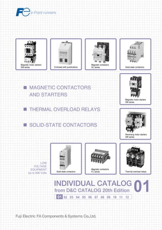
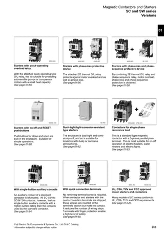
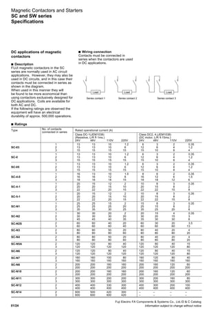
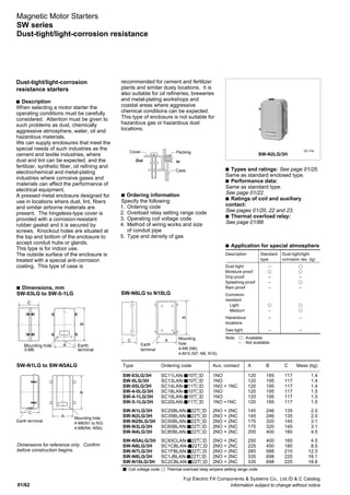
Frame size
Frame size
Ampere setting range [A]
Rated themal current [A]
11
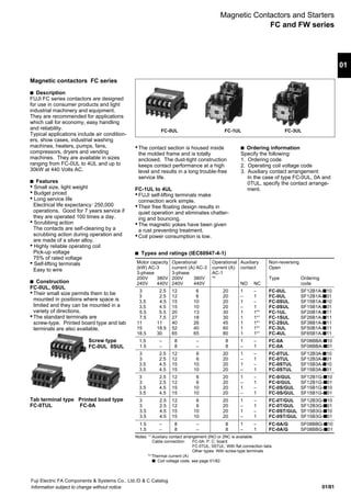
Magnetic Contactors and Starters
General information](https://image.slidesharecdn.com/dec2001-contactor-141203004855-conversion-gate01/85/Dec2001-contactor-12-320.jpg)


![01/116
Fuji Electric FA Components & Systems Co., Ltd./D & C Catalog
Information subject to change without notice
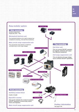
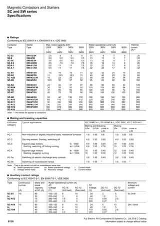
Magnetic Contactors and Starters
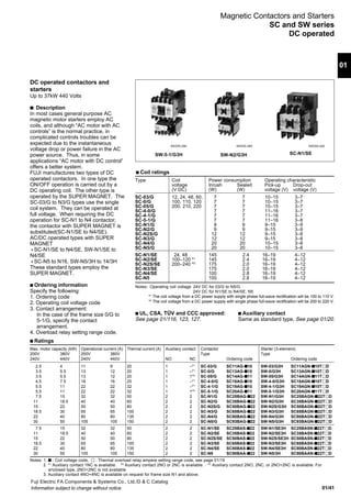
UL and CSA approved
Frame Max. motor capacity (HP) Rated Aux. AC operated DC operated
size conti- contact
200V 220V 440V 550V nuous NO NC Type Ordering Type Ordering
240V 480V 600V current code code
03 2 2 5 5 11A 1 – *1
SC-03 SC11AA-{10 q SC-03/G SC11AG-{10 q
0 3 3 5 5 13A 1 – *1
SC-0 SC13AA-{10 q SC-0/G SC13AG-{10 q
05 3 3 5 5 13A 1 1 *2
SC-05 SC14AA-{11 q SC-05/G SC14AG-{11 q
4-0 5 5 7.5 7.5 20A 1 – *1
SC-4-0 SC18AA-{10 q SC-4-0/G SC18AG-{10 q
4-1 5 5 10 10 20A 1 – *1
SC-4-1 SC19AA-{10 q SC-4-1/G SC19AG-{10 q
5-1 5 5 10 10 20A 1 1 *3
SC-5-1 SC20AA-{11 q SC-5-1/G SC20AG-{11 q
N1 7.5 10 25 25 50A 2 2 *4
SC-N1 SC25BAA-{22 q SC-N1/G SC25BAG-{22 q
N2 10 15 30 30 60A 2 2 *4
SC-N2 SC35BAA-{22 q SC-N2/G SC35BAG-{22 q
N2S 15 20 40 40 80A 2 2 *4
SC-N2S SC50BAA-{22 q SC-N2S/G SC50BAG-{22 q
N3 20 25 50 50 100A 2 2 *4
SC-N3 SC65BAA-{22 q SC-N3/G SC65BAG-{22 q
N4 25 30 60 60 135A 2 2 *4
SC-N4 SC80BAA-{22 q SC-N4/G SC80BAG-{22 q
N5 30 30 60 75 150A 2 2 *4
SC-N5A SC93CAA-{22 q SC-N5/G SC93BAG-{22 q
N6 40 40 75 100 150A 2 2 *4
SC-N6 SC1CBAA-{22 q SC-N6 SC1CBAA-{22 q
N7 50 50 100 125 200A 2 2 *4
SC-N7 SC1FBAA-{22 q SC-N7 SC1FBAA-{22 q
N8 60 60 150 150 260A 2 2 *4
SC-N8 SC1JBAA-{22 q SC-N8 SC1JBAA-{22 q
N10 75 75 150 200 260A 2 2 *4
SC-N10 SC2CBAA-{22 q SC-N10 SC2CBAA-{22 q
N11 100 100 200 250 350A 2 2 *4
SC-N11 SC3ABAA-{22 q SC-N11 SC3ABAA-{22 q
N12 125 150 300 350 450A 2 2 *4
SC-N12 SC4ABAA-{22 q SC-N12 SC4ABAA-{22 q
N14 200 200 500 600 660A 2 2 *4
SC-N14 SC6ABAA-{22 q SC-N14 SC6ABAA-{22 q
N16 250 300 600 700 800A 2 2 *4
SC-N16 SC8ABAA-{22 q SC-N16 SC8ABAA-{22 q
N1 7.5 10 25 25 50A 2 2 *4
SC-N1/SE SC25BAS-{22 q SC-N1/SE SC25BAS-{22 q
N2 10 15 30 30 60A 2 2 *4
SC-N2/SE SC35BAS-{22 q SC-N2/SE SC35BAS-{22 q
N2S 15 20 40 40 80A 2 2 *4
SC-N2S/SE SC50BAS-{22 q SC-N2S/SE SC50BAS-{22 q
N3 20 25 50 50 100A 2 2 *4
SC-N3/SE SC65BAS-{22 q SC-N3/SE SC65BAS-{22 q
N4 25 30 60 60 135A 2 2 *4
SC-N4/SE SC80BAS-{22 q SC-N4/SE SC80BAS-{22 q
s Ordering information
Specify the following:
1. Ordering code
2. Overload relay setting range code
3. Operating coil voltage code
SW-N1
KK04-090
SB-2N/SEUL FC-0UL
R
R
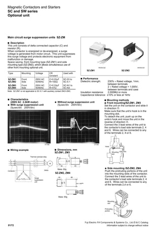
UL and CSA approved
Up to 300HP 240V AC, 3-phase
s Description
FUJI high quality contactors and starters
conform to UL and CSA requirements as
they are.
These have high standards of efficiency
and safety and are being used
throughout the world. We can
recommend them with confidence.
Other advantages are that they take up
less installation space, are easily
installed and can replace other starters
without trouble because of their
compact size.
UL [File No. E42419, E44592], CSA [File No. LR20479]
Non reversing contactors (Open type)
SC-N3
Notes: q Available
{ Coil voltage code
*1
Auxiliary contact 1NC is available on request.
*2
Auxiliary contact 2NO or 2NC is available on request.
*3
Auxiliary contact 2NO or 2NC or 2NO+2NC is available on request.
*4
Auxiliary contact 4NO+4NC is available on request for frame sizes N1 and above.
KK05-049 AF89-728 KKD06-052](https://image.slidesharecdn.com/dec2001-contactor-141203004855-conversion-gate01/85/Dec2001-contactor-130-320.jpg)


![01/120
Fuji Electric FA Components & Systems Co., Ltd./D & C Catalog
Information subject to change without notice
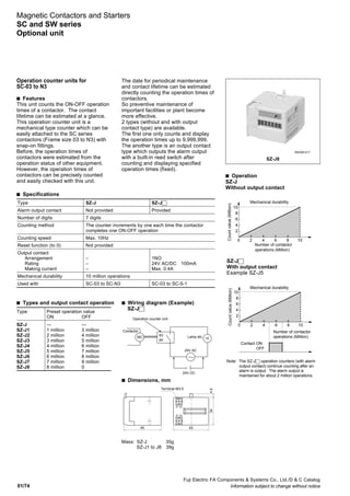
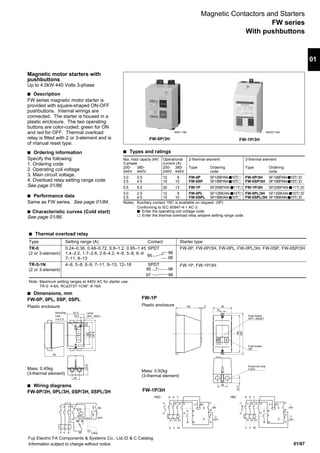
Magnetic Contactors and Starters
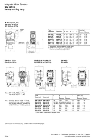
UL and CSA approved
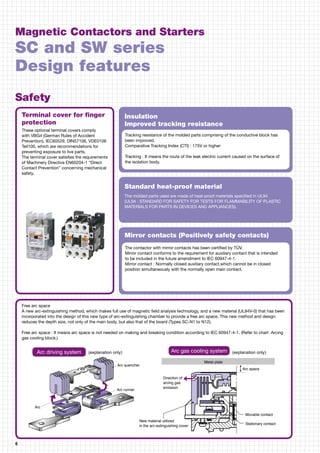
DC contactor SB series UL [File No. E42419], CSA [File No. LR20479]
Type Ordering Main contact
code arrangement
SB-2N/UL SB351AA-{Ǣ 2NO
SB-2NB/UL SB351AB-21{Ǣ 2NO+1NC
SB-2N/SEUL SB351SA-{Ǣ 2NO
SB-2NB/SEUL SB351SB-21{Ǣ 2NO+1NC
SB-5N/UL SB851BA-{Ǣ 2NO
SB-5NB/UL SB851BB-{Ǣ 2NO+1NC
SB-6N/UL SB1C1BA-{Ǣ 2NO
SB-6NB/UL SB1C1BB-{Ǣ 2NO+1NC
SB-10N/UL SB2A1BA-{Ǣ 2NO
SB-10NB/UL SB2A1BB-{Ǣ 2NO+1NC
SB-11N/UL SB2K1BA-{Ǣ 2NO
SB-11NB/UL SB2K1BB-{Ǣ 2NO+1NC
Notes: • Enter the coil voltage code in the { mark.
• Enter the auxiliary contact arrangement in the Ǣ mark.
• 22: 2NO+2NC (standard), 33: 3NO+3NC (on request),
44: 4NO+4NC (on request)
*1
NO contacts are capable of making 2 times of listed current ratings.
*2
NC contacts are capable of making 1 time of listed current ratings.
Continuous
current (A)
NO NC
50 50
50 50
110 100
140 100
240 160
320 200
2NO (in series)*1
110V/240V 440V/500V
50 35
50 35
110 110
140 140
240 240
320 320
1NC (dynamic brake)*2
110V/240V 440V/500V
75 75
75 75
165 165
210 210
360 360
480 480
2NO (in series)
110V 240V 440V 500V
40 35 18 15
40 35 18 15
85 85 60 45
125 120 80 50
240 200 120 100
320 290 200 150
Current ratings (A)
Variable-speed motor control DC motor control (DC2, class4)
q Auxiliary contact ratings
Rating Continuous Current ratings (A)
code current (A) Voltage Make Break
A600 10 120V AC 60 6
240V AC 30 3
480V AC 15 1.5
600V AC 12 1.2
Q300 10 125V DC 0.55 0.55
250V DC 0.27 0.27
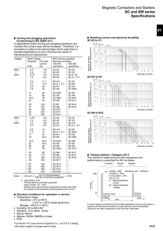
Description Type Ordering Used
code with
Auxiliary Front SZ-A40 SZ1A40 4NO SC-03 to 5-1
contact mounting SZ-A31 SZ1A31 3NO+1NC SH-4,5
block SZ-A22 SZ1A22 2NO+2NC SC-N1 to N3
SZ-A20 SZ1A20 2NO
SZ-A11 SZ1A11 1NO+1NC
SZ-A02 SZ1A02 2NC
Side SZ-AS1 SZ1AS1 1NO+1NC SC-03 to N3
mounting SZ-AS2 SZ1AS2 1NO+1NC SC-N4 to N12
Mechanical SZ-RM SZ1RM SC-03 to 5-1
interlock unit SC-N1 to N3
Coil Varistor SZ-Z1 SZ1Z1 24 to 48V AC/DC SC-03 to 5-1
surge SZ-Z2 SZ1Z2 100 to 250V AC/DC SH-4, 5
suppres- SZ-Z3 SZ1Z3 380 to 440V AC/DC
sion SZ-Z6*2
SZ1Z6 24 to 48V AC/DC
unit SZ-Z7*2
SZ1Z7 100 to 250V AC/DC
SZ-Z31 SZ2Z31 24 to 48V AC/DC SC-N1 to N3
SZ-Z32 SZ2Z32 100 to 250V AC/DC SC-N1/G to N3/G
SZ-Z33 SZ2Z33 380 to 440V AC/DC SC-N1 to N3
SZ-Z41 SZ2Z41 24 to 48V AC SC-N4, N5A
SZ-Z42 SZ2Z42 100 to 250V AC
SZ-Z43 SZ2Z43 380 to 440V AC
CR SZ-Z4 SZ1Z4 24 to 48V AC/DC SC-03 to 5-1
SZ-Z5 SZ1Z5 100 to 250V AC/DC SH-4, 5
SZ-Z8*2
SZ1Z8 24 to 48V AC/DC
SZ-Z9*2
SZ1Z9 100 to 250V AC/DC
SZ-Z34 SZ2Z34 24 to 48V AC SC-N1 to N3
SZ-Z35 SZ2Z35 100 to 250V AC
SZ-Z36 SZ2Z36 24 to 48V DC SC-N1/G to N3/G
SZ-Z37 SZ2Z37 100 to 250V DC
SZ-Z44 SZ2Z44 24 to 48V AC SC-N4, N5A
SZ-Z45 SZ2Z45 100 to 250V AC
Notes: *1
Overlapping
*2
With LED
Description Type Ordering Used with
code
Main circuit surge SZ-ZM1 SZ1ZM1 SC-03 to 5-1
suppression unit SZ-ZM2 SZ1ZM2 SC-03 to 5-1
SZ-ZM3 SZ1ZM3 SC-N1 to N3
SZ-ZM4 SZ1ZM4 SC-N1 to N3
Terminal For contactor SZ-T1 SZ1T1 SC-03, 0, SH-4
cover and industrial SZ-T2 SZ1T2 SC-05, SH-5
relay SZ-T3 SZ1T3 SC-4-0, 4-1
SZ-T4 SZ1T4 SC-5-1
SZ-T22 SZ2T22 SC-N1, N2
SZ-T23 SZ2T23 SC-N2S, N3
SZ-N4T SZ2N4T SC-N4, N5, SW-N4/3H, N5A/3H
SZ-N6T SZ2N6T SC-N6, SW-N6/3H
SZ-N7T SZ2N7T SC-N7, SW-N7/3H
SZ-N8T SZ2N8T SC-N8, N10, SW-N8/3H, N10/3H
SZ-N11T SZ2N11T SC-N11, N12, SW-N11/3H, N12/3H
SZ-WN4T SZ2WN7T SW-N4/3H, N5A/3H
SZ-WN6T SZ2WN7T SW-N6/3H
SZ-WN7T SZ2WN7T SW-N7/3H
SZ-WN8T SZ2WN7T SW-N8/3H
SZ-WN10T SZ2WN7T SW-N10/3H
SZ-WN11T SZ2WN7T SW-N11/3H, N12/3H
For auxiliary SZ-T5 SZ1T5 SZ-A40, SZ-A31, SZ-A22
contact block SZ-T6 SZ1T6 SZ-A20, SZ-A11, SZ-A02
SZ-T7 SZ1T7 SZ-AS1, SZ-AS2
For thermal SZ-T10 SZ1T10 SZ-HB
overload relay SZ-T11 SZ1T11 SZ-HC
SZ-T12 TZ1T12 TR-0N/3, TK-0N
SZ-T13 TZ1T13 TR-5-1N/3, TK-5-1N
SZ-T14 SZ2T14 TR-N2H/3, TK-N2H
SZ-T15 SZ2T15 TR-N3H/3, TK-N3H
SZ-RN6T SZ2RN6T TR-N6H/3, TK-N6H
SZ-T16 SZ2T16 TR-N2/3, TK-N2
SZ-T17 SZ2T17 TR-N3/3, TK-N3
Base unit for SZ-HB TZ1HB TR-0N/3, TK-0N
separate mounting SZ-HC TZ1HC TR-5-1N/3, TK-5-1N
SZ-HD TZ2HD TR-N2/3, TK-N2
SZ-HE TZ2HE TR-N3/3, TK-N3
Reset release SZ-R1 TZ1R1 TR-0N/3, TK-0N, TR-5-1N/3
button SZ-R2 TZ1R2 TK-5-1N
SZ-R3 TZ1R3 TR-N10/3 to N14/3, TK-N10 to N14
SZ-R4 TZ2R4 TR-N2/3 to N8/3
SZ-R5 TZ2R5 TK-N2 to N8
SZ-R6 TZ2R6
Dial cover SZ-DA SZ1DA TR-0N/3 to N14/3
TK-0N to TK-N14
q Dimensions
Same as standard type
See page 01/81.
Optional units UL[File No. E42419], CSA [File No. LR20479]
• On-load factor is 50%, operating cycle is 600 cycles per hour.
• Breaking condition : No voltage](https://image.slidesharecdn.com/dec2001-contactor-141203004855-conversion-gate01/85/Dec2001-contactor-134-320.jpg)
![01/121
01
Fuji Electric FA Components & Systems Co., Ltd./D & C Catalog
Information subject to change without notice
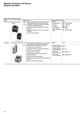
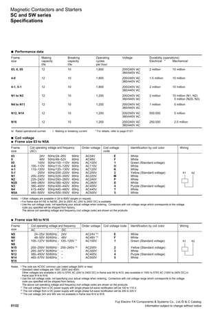
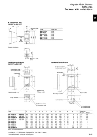
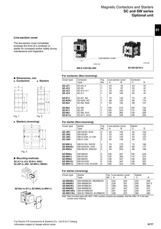
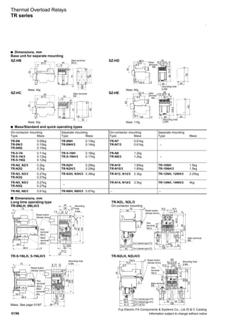
Definite purpose contactors UL [File No. E42419], CSA [File No. LR20479]
Type Ordering Terminal Auxiliary contact Motor capacity (HP) Thermal continuous current (A)
code arrangement Single-phase 3-phase
110V 220V 200V 220V 440V 550V
120V 240V 240V 480V 600V
FC-0UL SF12B1A-s10*1
q Screw 1NO 1/2 1 1 1 – – 15
FC-0TUL SF12B3A-s10*1
q Tab
FC-0SUL SF15B1A-s10*1
q Screw
FC-0STUL SF15B3A-s10*1
q Tab
FC-1UL SF20B1A-s11*2
q Screw 1 2 5 5 7.5 7.5 20
FC-1SUL SF26B1A-s11*2
q Screw 1NO +1NC 2 3 5 7.5 10 7.5 26
FC-2SUL SF38B1A-s11*2
q Screw 3 5 10 10 15 10 35
FC-3UL SF50B1A-s11*2
q Screw 3 7.5 10 15 25 15 45
FC-4UL SF65B1A-s11*2
q Screw 5 10 15 20 30 25 65
FC-0/GUL SF12B1G-s10*1
q Screw 1NO 1/2 1 1 1 – – 15
FC-0T/GUL SF12B3G-s10*1
q Tab
FC-0S/GUL SF15B1G-s10*1
q Screw
FC-0ST/GUL SF15B3G-s10*1
q Tab
Notes: *1
1NO is standard, 1NC is also available on request. q Approved s Coil voltage code
*2
1NO+1NC is standard, 2NO or 2NC is also available on request.
FC-0/GUL, 0T/GUL
FC-0S/GUL, 0ST/GUL
Voltage Code
24V DC E
48V DC F
100V DC 1
110V DC H
200V DC 2
220V DC M
Operating coil voltage
FC-0UL, 0TUL, 0SUL, 0STUL, 1UL,
FC-1SUL, 2SUL, 3UL, 4UL
Voltage and frequency Code
24V 50Hz/24 – 26V 60Hz E
48V 50Hz/48 – 52V 60Hz F
100V 50Hz/100 – 110V 60Hz 1
100 – 110V 50Hz/110 – 120V 60Hz H
110 – 120V 50Hz/120 – 130V 60Hz K
200V 50Hz/200 – 220V 60Hz 2
200 – 220V 50Hz/220 – 240V 60Hz M
s Dimensions, mm
See page 01/83.
s Wiring diagrams
FC-0UL, 0TUL, 0/GUL, 0T/GUL
FC-0SUL, 0STUL, 0S/GUL, 0ST/GUL
1NO
1NO+1NC
FC-1UL, 1SUL, 2SUL, 3UL, 4UL
1NO+1NC
1 3 5 13
A1
A22 4 6 14
13 1 3 5
A1
14 2 4 6
A2
22
21
A1
A2
13 1 3 5 21
14 2 4 6 22
Type Rating code Thermal Current ratings Maximum
continuous (A) (VA)
current 120V AC 240V AC 480V AC 600V AC
(A) Make Break Make Break Make Break Make Break Make Break
FC-0UL B300 5 30 3 15 1.5 – – – – 3600 360
FC-0TUL
FC-0SUL
FC-0STUL
FC-1UL A600 10 60 6 30 3 15 1.5 12 1.2 7200 720
FC-1SUL
FC-2SUL
FC-3UL
FC-4UL
FC-0/GUL B300 5 30 3 15 1.5 – – – – 3600 360
FC-0T/GUL
FC-0S/GUL
FC-0ST/GUL
Auxiliary contact ratings
Magnetic Contactors and Starters
UL and CSA approved](https://image.slidesharecdn.com/dec2001-contactor-141203004855-conversion-gate01/85/Dec2001-contactor-135-320.jpg)
![01/122
Fuji Electric FA Components & Systems Co., Ltd./D & C Catalog
Information subject to change without notice
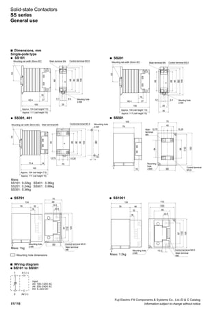
Solid-state contactors SS series UL [File No. E132864, E142975]
Single pole type
q Main circuit 240V AC, SS101 to SS2001
Type SS101-5Z-A3 SS201-5Z-A3 SS301-5Z-A3 SS401-5Z-A3 SS501-5Z-A3
SS101-5Z-A4 SS201-5Z-A4 SS301-5Z-A4 SS401-5Z-A4 SS501-5Z-A4
SS101-3Z-D3 SS201-3Z-D3 SS301-3Z-D3 SS401-3Z-D3 SS501-3Z-D3
Ordering code SS101-5ZA3 SS201-5ZA3 SS301-5ZA3 SS401-5ZA3 SS501-5ZA3
SS101-5ZA4 SS201-5ZA4 SS301-5ZA4 SS401-5ZA4 SS501-5ZA4
SS101-3ZD3 SS201-3ZD3 SS301-3ZD3 SS401-3ZD3 SS501-3ZD3
Rated thermal current(A) * 10 20 30 40 50
Control voltage A3 : 100V-120V AC, A4 : 200-240V AC, D3 : 5-24V DC
Type SS701-1Z-A3 SS1001-1Z-A3 SS1501-1Z-A3 SS2001-1Z-A3
SS701-1Z-A4 SS1001-1Z-A4 SS1501-1Z-A4 SS2001-1Z-A4
SS701-3Z-D3 SS1001-3Z-D3 SS1501-3Z-D3 SS2001-3Z-D3
Ordering code SS701-1ZA3 SS1A1-1ZA3 SS1F1-1ZA3 SS1A1-1ZA3
SS701-1ZA4 SS1A1-1ZA4 SS1F1-1ZA4 SS1A1-1ZA4
SS701-3ZD3 SS1A1-3ZD3 SS1F1-3ZD3 SS1A1-3ZD3
Rated thermal current(A) * 70 100 150 200
Control voltage A3 : 100V-120V AC, A4 : 200-240V AC, D3 : 5-24V DC
q Main circuit 480V AC
Contactor Cooling fin to be combined Continuous Motor ratings
3-pole, 2-element 3-pole, 3-element 3-pole, 2-element 3-pole, 3-element current 3-phase 440V AC 60Hz
Basic Basic Basic Basic Basic Basic Basic Basic Capacity Full load current
type ordering type ordering type ordering type ordering (HP) (A)
code code code code (A)
SS302H SS302H SS303H SS303H SX1-E12 SY1E2 SX1-E12 SY1E2 30 – –
SS502H SS502H SS503H SS503H SX1-E12 SY1E2 SX1-E17 SY1E7 50 10 17
SS802H SS802H SS803H SS803H SX1-C12 SY1C2 SX1-C12 SY1C2 80 20 32.5
SS1202H SS1C2H SS1203H SS1C3H SX1-C12 SY1C2 SX1-C12 SY1C2 120 20 32.5
q Main circuit 480V AC, SS701H to SS2001H
Type SS701H-1Z-A3 SS1001H-1Z-A3 SS1501H-1Z-A3 SS2001H-1Z-A3
SS701H-1Z-A4 SS1001H-1Z-A4 SS1501H-1Z-A4 SS2001H-1Z-A4
SS701H-3Z-D3 SS1001H-3Z-D3 SS1501H-3Z-D3 SS2001H-3Z-D3
Ordering code SS701H-1ZA3 SS1A1H-1ZA3 SS1F1H-1ZA3 SS1A1H-1ZA3
SS701H-1ZA4 SS1A1H-1ZA4 SS1F1H-1ZA4 SS1A1H-1ZA4
SS701H-3ZD3 SS1A1H-3ZD3 SS1F1H-3ZD3 SS1A1H-3ZD3
Rated thermal current(A) * 70 100 150 200
Control voltage A3 : 100V-120V AC, A4 : 200-240V AC, D3 : 5-24V DC
Note: * The values are maximum ratings that apply at an ambient temperature not exceeding 40°C.
q Input voltage
100–120/200–240V AC
100–120V AC
200–240V AC
12/24V DC
12–24V DC
5V DC
5–24V DC
Note: For details, see page 01/119.
3-pole type
q Main circuit 240V AC
Contactor Cooling fin to be combined Continuous Motor ratings
3-pole, 2-element 3-pole, 3-element 3-pole, 2-element 3-pole, 3-element current 3-phase 220V AC 60Hz
Basic Basic Basic Basic Basic Basic Basic Basic Capacity Full load current
type ordering type ordering type ordering type ordering (HP) (A)
code code code code (A)
SS032 SS032 SS033 SS033 – – – – 3 1/2 2
SS082 SS082 SS083 SS083 * * * * 8 3/4 2.9
SS202 SS202 SS203 SS203 SX1-D10 SY1D0 SX1-D10 SY1D0 20 1 1/2 5.2
SS302 SS302 SS303 SS303 SX1-D10 SY1D0 SX1-E12 SY1E2 30 2 5.8
SS402 SS402 SS403 SS403 SX1-D14 SY1D4 SX1-E12 SY1E2 40 3 9.6
SS502 SS502 SS503 SS503 SX1-E12 SY1E2 SX1-E17 SY1E7 50 5 15.2
SS802 SS802 SS803 SS803 SX1-C12 SY1C2 SX1-C12 SY1C2 80 10 28
SS1202 SS1C2 SS1203 SS1C3 SX1-C12 SY1C2 SX1-C12 SY1C2 120 10 28
Note: * Cooling fin provided
Magnetic Contactors and Starters
UL and CSA approved](https://image.slidesharecdn.com/dec2001-contactor-141203004855-conversion-gate01/85/Dec2001-contactor-136-320.jpg)


The document provides information on Fujielectric's low voltage equipment catalog, including magnetic contactors, starters, thermal overload relays, and solid-state contactors. It summarizes key specifications and features of their SC and SW series contactors and starters, such as long electrical life of 2 million operations, easy addition of optional modules, meeting various international standards, and employing new technologies like their Super Magnet for reliable performance. The document is intended to introduce readers to Fujielectric's low voltage product catalog and provide an overview of their magnetic contactors and starters.


