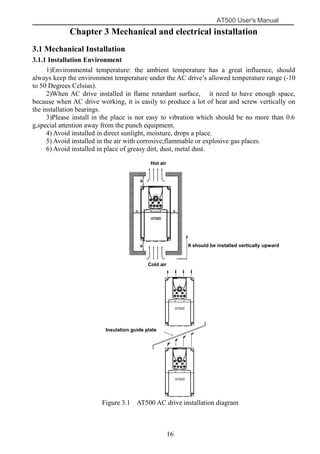
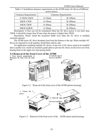
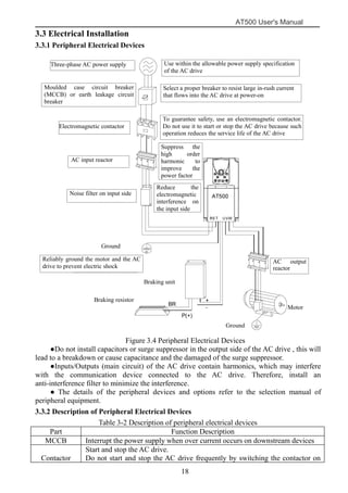
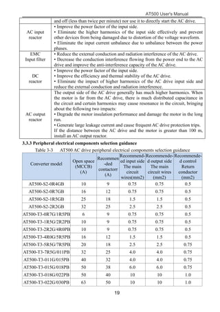
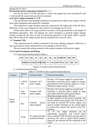
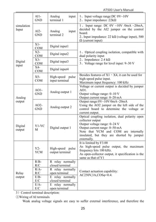
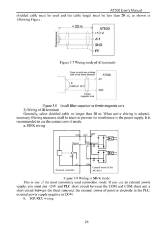
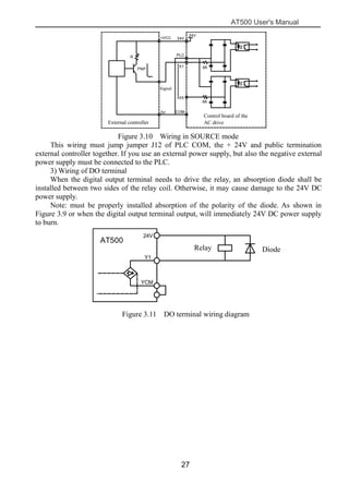
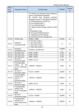
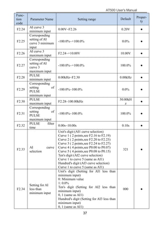
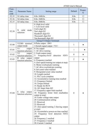
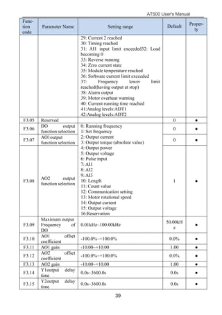
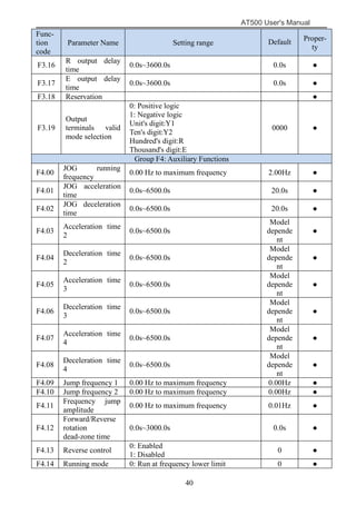
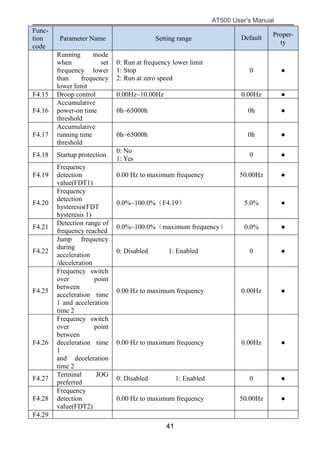
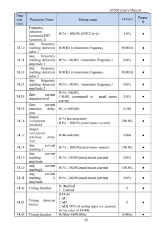
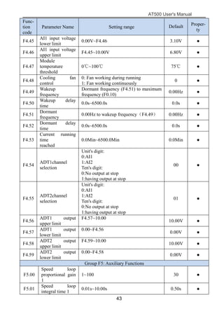
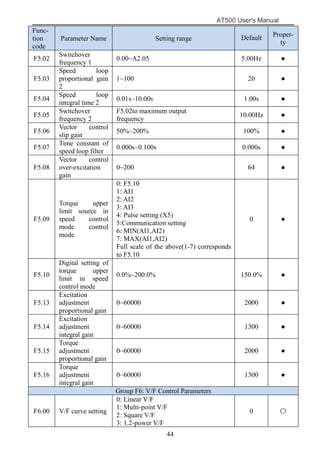
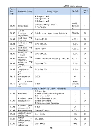
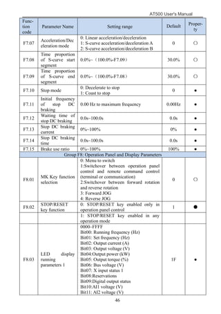
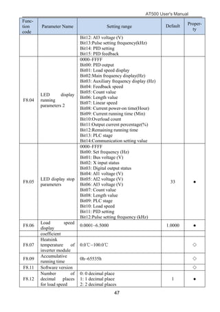
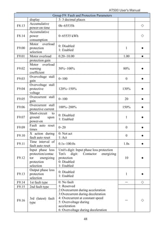
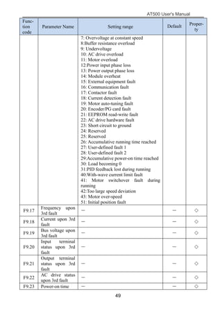
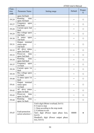
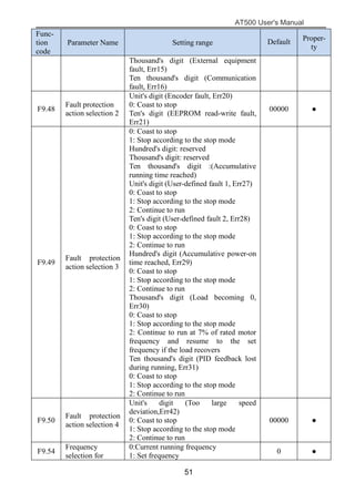
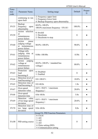
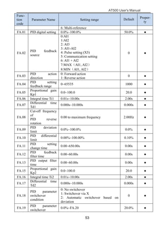
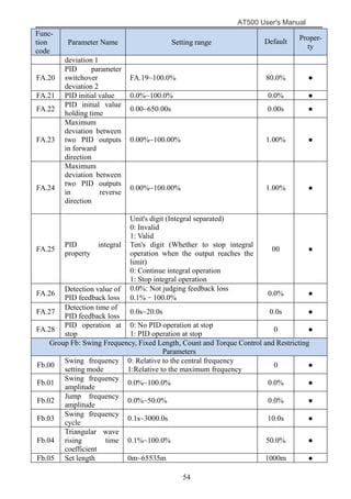
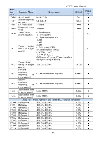
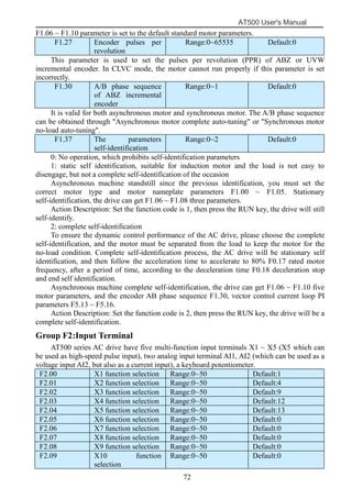
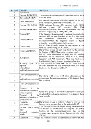
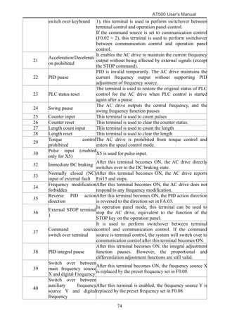
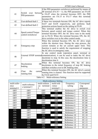
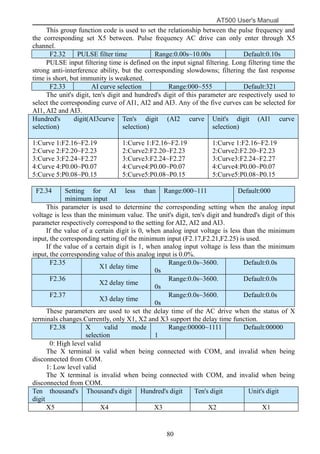
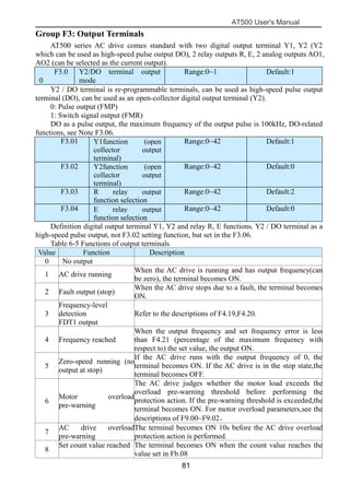
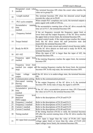
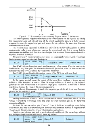
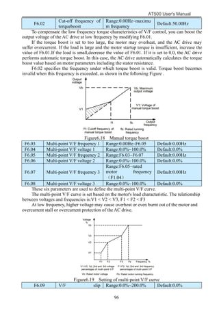
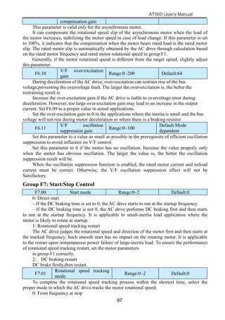
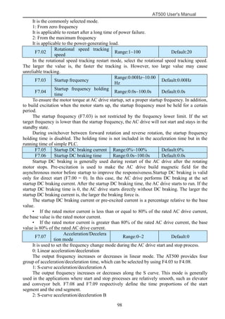
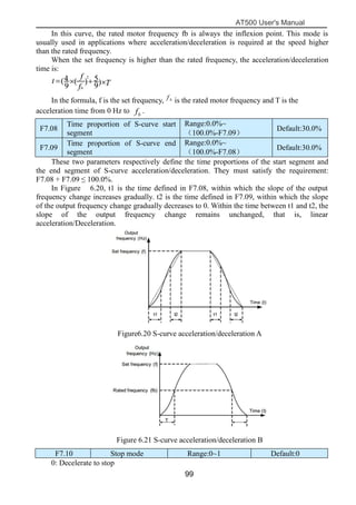
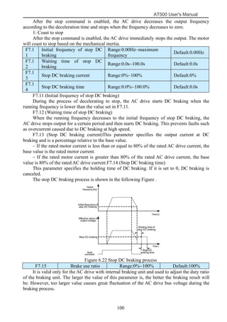
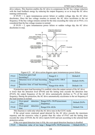
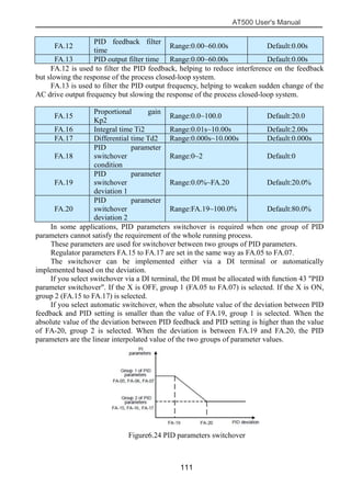
AT500 User's Manual
1
Preface
The AT500 series AC drive is a general-purpose high-performance current
vector control AC drive. It can implement the control of asynchronous motor. It is
used to drive various automation production equipment involving textile,
paper-making, wire drawing, machine tool, packing, food, fan and pump.
This manual describes the correct use of the AT500 series AC drive, including
selection, parameter setting, commissioning, maintenance & inspection. Read and
understand the manual before use and forward the manual to the end user.
Note matter
 The drawings presented in this instructions are sometimes
shown without covers or protective guards.Always replace the equipment’s
cover or protective guard as specified first,and the operate the products in
accordance with the instructions.
 The drawings presented in the instructions are typical examples
and may not match the product you received.
 These instructions are subject to change due to product
improvement,specification modification, specification modification.
 If you want to order the manual due to loss or damage, please
contact our company agents in each region or our company customer
service center directly.
 If there is still any problem during using the product, please
contact our company customer service center directly.
:
AT500 User's Manual
2
Contents
Preface.......................................................................................................... 1
Chapter 1 Safety information and precautions.........................................3
1.1 Security matters............................................................................... 3
1.2 Notes................................................................................................5
Chapter 2 Product information..................................................................8
2.1 Naming rules....................................................................................8
2.2 Nameplate........................................................................................8
2.3 AT500 series AC drive....................................................................8
2.4 Product description of each part.................................................... 10
2.5 Technical Specifications................................................................10
2.6 Appearance and installation dimensions....................................... 13
2.7 Appearance and installation size keyboard....................................14
2.8 Appearance and hole size keyboard tray....................................... 15
Chapter 3 Mechanical and electrical installation................................... 16
3.1 Mechanical Installation..................................................................16
3.2 Products cover disassembly...........................................................17
3.3 Electrical Installation.....................................................................18
3.4 Selection of Braking Unit and Braking Resistor........................... 20
3.5 Wiring of AC drive Control Circuit...............................................22
Chapter 4 Operating and display...........................................................28
4.1 Operation and display interface.....................................................28
4.2 Viewing and Modifying Function Codes...................................... 29
Chapter5 Function Parameter List..........................................................31
Chapter6 Parameter Description.......................................................... 65
Group F0: Basic Function....................................................................65
Group F1: Motor parameters............................................................... 71
Group F2: Input Terminal....................................................................72
Group F3: Output Terminals............................................................... 81
Group F4: Auxiliary Functions............................................................85
Group F5: Vector Control Parameters.................................................93
Group F6: V/F Control Parameters......................................................95
Group F7: Start/Stop Control...............................................................97
Group F8: Operation Panel and Display............................................101
Group F9: Fault and Protection......................................................... 103
Group FA: Process Control PID Function.........................................109
Group FB: Swing Frequency, Fixed Length,Count and Torque Control
Parameters........................................................................113
Group FC: Multi-Reference and Simple PLC Function Parameters. 116
Group FD: User-defined Parameters................................................ .119
Group FE: Quick Menu parameters...................................................119
Group P0: Analog four points offset parameters...............................120
Group P1: Analog calibration parameters......................................... 122
Group H0: Monitoring Parameters....................................................123
Chapter 7 Maintenance and Troubleshooting...................................... 125
7.1 Routine Repair and Maintenance of the AT500..........................125
7.2 Warranty Agreement................................................................... 126
7.3 Faults and Solutions.....................................................................126
7.4 Common Faults and Solutions.....................................................130
AT500 User's Manual
3
Chapter 1 Safety information and precautions
Safety definition:
In this manual, Safety cautions are divided into two types:
Danger: since not according to the requirements of the operating cause danger, may
result in serious injury or death.
Note:since not according to the requirements of the operating cause danger, may cause
moderate damage or minor injuries, and equipment damage.
Please users carefully reading this chapter and must according to the requirements of
safety cautions in this chapter to operate when you install, debug and maintain this
system. it is nothing to do with our company If appear any damage and loss due to
violate compasses operation.
1.1 Security matters
1.1.1 Before installation
Danger
●Found control system fill into water when unpacking,lack of
component or component parts damaged, please do not install!
●Packing list with real names do not match, please do not install!
Danger
● Handling should light , or damage the equipment of danger!
● Please don't use damaged or lack of parts AC drive . A risk of injury!
● Don't use hand to touch control system’s components, it may cause
electrostatic damage!
1.1.2 During installation
Danger
●Please install in metal flame retardant objects; Away from the fuel. Or
it may cause a fire!
●Shall not turned the standing bolt of equipment components casually,
especially with red marking of bolt!
1.1.3 Wiring
Danger
●Please comply with the guidance of this manual, installing by the
professional electrical engineering staff , otherwise it will appear
unexpected danger!
●The power supply and the AC drive should be separated, or it may
AT500 User's Manual
4
cause fire!
●Please confirm the power supply in zero energy state before
connection , or you will get an electric shock risk!
●Please according to the standard of AC drive for correct standard
grounding, or you will get an electric shock risk!
Danger
●Don’t connected the power to the output terminals (U, V, W) the AC
drive. Note terminals mark, do not take the wrong line! Otherwise it will
cause the damage!
●Ensure that the circuit match with EMC requirements and afety
standards.please reference manual Suggestions the wire line diameter . Or
you could accident!
●Don’t directly connect braking resistance by dc bus (+), (-) between
terminals. Otherwise it will cause fire!
●Encoder must use the shielded wire, and shielding layer must ensure
that the single-ended reliable grounding!
1.1.4 Before energizing
Danger
● Please confirm the input power supply voltage grade; Please confirm
the connection between the power input terminals (R, S, T) and output
terminals (U, V, W) are correct; And Be aware of any short in the outside
circuit connected to the AC drive, whether the line is tighten, or it will cause
the damage to the AC drive!
● Any part of the AC drive need not to carry on pressure test, the factory
has done this before leaving factory . Otherwise it will cause accidents!
Danger
● The AC drive must be covered before power on. Or it may cause a
shock!
● All peripheral accessories of wiring must abide by this manual
guidance and connect according to the manual provided circuit connection
method. Otherwise it will cause accident!
1.1.5 After energizing
Danger
● After power up don't open cover plate. Or it can get an electric shock !
● Don't use wet hand to touch AC drive and its peripheral circuit. Or it
can get an electric shock !
● Don’t touch any of the AC drive’s input and output terminals. Or it can
AT500 User's Manual
5
get an electric shock!
●At the beginning of the power on,the automatic system of the AC drive
will check the high voltage outside, at this time,you should never touch the U,
V, W terminals or motor terminals of AC drive, or it will get an electric
shock!
Danger
● If the motor parameters need to be identified, please pay attention to
the danger when the motor rotating. Or it may cause accident!
● Please don’t change AC drive’s manufacturer parameters optionally.
Otherwise it may cause equipment damaged!
1.1.6 Running
Danger
● Please don’t touch the cooling fans and the discharge resistance in
order to test temperature. Or it may cause burns!
●Amateur technicians don’t test signals when AC drive running. Or it
may cause a personal injury or damage to the equipment.
Danger
● Avoiding anything fall into the equipment when the AC drive running .
Or it will cause the equipment damaged.
● Don’t use contactor to control the AC drive. Or it will cause equipment
damaged.
1.1.7 Maintenance
Danger
●Please don’t repair or maintain the equipment. Or it can get an electric
shock!
●Confirm in less than 36V voltage AC drive to implementation in the
maintenance and repair, when the power to fifteen minutes shall prevail.
Otherwise the remnants of the charge to the capacitance will cause damage!
●Without professional training personnel don’t repair and maintain AC
drive. Otherwise it will cause personal injury or damage to the equipment.
●Please set parameters value after changing the AC drive , all the
pluggable must be inserted after power off.
1.2 Notes
1.2.1 Motor insulation inspection
The motor insulation must be inspected when motor for the first time used or unused for a
long time, in case the effectiveness of the winding insulation to damage the AC drive. Motor
AT500 User's Manual
6
attachment must separate from AC drive when insulated inspection, suggested the 500 V
voltage type megameter,guarantee the insulation resistance not less than 5 MΩ.
1.2.2 Motor of the thermal protection
If choose motor and converter does not match the rated capacity, especially the rated
power greater than motor AC drive power rating, be sure to adjust the AC drive motor
protection in related parameters value or in motor with thermal relay to before to motor
protection.
1.2.3 Power frequency above operation
This AC drive can provide 0 Hz ~ 600 Hz output frequency. If the customer needs to be
in frequency 50 Hz above operation, please consider the strength of the mechanical device.
1.2.4 The vibration of mechanical device
AC drive may meet load machinery’s mechanical resonance point in some output
frequency place,it can be set hopping frequency and parameters within the AC drive to avoid.
1.2.5 Motor fever and noise
Because the AC drive’s output voltage is PWM waves, contain certain harmonic ,
therefore, the rise of temperature of the motor, noise and vibration frequency will run little
increase.
1.2.6 When therer are pressure sensitive devices or capacitance to improve the power
factor on the output side
AC drive is PWM waves, the output side such as the capacitor with improving electrical
power factor or the lightning protection with pressure sensitive resistance, it easy cause
instantaneous AC drive over current even damage AC drive, please do not use.
1.2.7 The input and output terminal contactor of switching element etc
If contactor is between the power and AC drive input side , it is not allowed to use this
contact device control AC drive to the rev. stop. It need to use this contractor to control the AC
drive rev. Stopping , interval an hour at least. Frequent charge-discharge is easily reduce the
AC drive of the capacito the service lifer. If the output and motor with contact between the
switch device, shall ensure that no output AC drive in the hige operation, or it easily cause AC
drive module damaged.
1.2.8 Rated voltage value the use of outside
Not suitable for user manual in the provisions of the voltage range allowed outside use
AT series AC drive, it easily cause the AC drive device damaged.If it necessary, please use the
corresponding or step down device to deal with variable pressure.
1.2.9 Change the three-phase input into the two phase input
Don’t change the three-phase AC drive into the two phase in AT series. Otherwise it will
lead to malfunction or damage the AC drive.
1.2.10 Lightning shock protection
This series of AC drive is equipped with a lightning over current protection device,having
certain ability of self-protection for indirect lightning.In the frequent lightning place,please
install the protective devices at the front end of the AC drive.
1.2.11 The altitude and derating using
At an altitude of more than 1000m area, because thin air cause the AC drive cooling effect
becoming poor,so it is necessary to derate use. Please consult our company for technique in
this situation.
AT500 User's Manual
7
1.2.12 Some special usage
If the customer was using when required to book recommendations provided by methods
other than when wiring diagram, such as dc bus, etc, please consult our company.
1.2.13 Converter scrap note
The main loop of the electrolytic capacitor and printed circuit boards electrolytic
capacitors on incineration can explode. Plastic incinerator will produce toxic gases. Please as
industrial waste processing.
1.2.14 Adapter motor
1)Standard adapter electric quadrupole squirrel-cage asynchronous induction motor. If
the motor please press the motor rated current selection of AC drive. If you need to drive
permanent magnet synchronous motor of the occasion, please consult our company.
2)A variable frequency motor cooling fan and rotor shaft is coaxially connected, speed is
reduced when the fan cooling effect is reduced, therefore, the motor overheat the occasion
should be equipped with strong exhaust fan or replacement for variable frequency motor.
3)Converter has a built-in adaptation motor standard parameters, according to the actual
situation it is necessary to motor parameter self identification or modify the default values so
as to accord with the actual value, otherwise it will affect the running effect and protection
performance.
4)Because the cable or motor internal short circuit can cause AC drive alarm, even frying
machine. Therefore, please first for the initial installation of the motor and cable insulation
short test, routine maintenance is often required for this test. Note, doing this test must be
tested part of AC drive and disconnect all.
AT500 User's Manual
8
Chapter 2 Product information
2.1 Naming rules
DR300 - T 3 - 011 G / 015 P
Inverter series
Code Voltage level
T
S
Three-Phase
Single-Phase
2
3
6
11
220V
380V
660V
1140V
G
P
Inverter type
Universal type
Fan pump type
7R5
011
015
018
022
030
Adapter motor power (KW)
7.5
11
15
18.5
22
30
Code Voltage level
Code
Code
Figure 2.1 Naming rules
2.2 Nameplate
Figure 2.2 AC drive brand of the data
2.3 AT500 series AC drive
Table 2-1 AT500 series AC drive
AC drive types Power supply
capacity
(KVA)
Input current
(A)
Rated output
current(A) G/P
Adapter motor
(KW) (HP)
Single-phase power supply: 220 v,50/60Hz
AT500-S2-0R4GB 1.0 5.4 2.3 0.4 0.5
AT500-S2-0R7GB 1.5 8.2 4.0 0.75 1
AT500-S2-1R5GB 3.0 14.0 7.0 1.5 2
AC drive types Power supply
capacity
(KVA)
Input current
(A)
Rated output
current(A) G/P
Adapter motor
(KW) (HP)
AT500-S2-2R2GB 4.0 23.0 9.6 2.2 3
AT500
AT500 User's Manual
9
Three-phase power supply: 380V,50/60Hz
AT500-T3-0R7G/1R5PB 1.5 3.4 2.1 0.75 1
AT500-T3-1R5G/2R2PB 3 5 3.8 1.5 2
AT500-T3-2R2G/4R0PB 4 5.8 5.1 2.2 3
AT500-T3-4R0G/5R5PB 5.9 10.5 9 3.7 5
AT500-T3-5R5G/7R5PB 8.9 14.6 13 5.5 7.5
AT500-T3-7R5G/011PB 11 20.5 17 7.5 10
AT500-T3-011G/015PB 17 26 25 11 15
AT500-T3-015G/018PB 21 35 32 15 20
AT500-T3-018G/022PB 24 38.5 37 18.5 25
AT500-T3-022G/030PB 30 46.5 45 22 30
AT500-T3-030G/037P 40 62 60 30 40
AT500-T3-037G/045P 57 76 75 37 50
AT500-T3-045G/055P 69 92 91 45 60
AT500-T3-055G/075P 85 113 112 55 75
AT500-T3-075G/090P 114 157 150 75 100
AT500-T3-090G/110P 134 180 176 90 125
AT500-T3-110G/132P 160 214 210 110 150
AT500-T3-132G/160P 192 256 253 132 200
AT500-T3-160G/185P 231 307 304 160 210
AT500-T3-200G/220P 250 385 377 200 270
AT500-T3-220G/250P 280 430 426 220 300
AT500-T3-250G/280P 355 468 465 250 335
AT500-T3-280G/315P 396 525 520 280 380
AT500-T3-315G/355P 445 590 585 315 420
AT500-T3-355G/400P 500 665 650 355 470
AT500-T3-400G/450P 565 785 725 400 530
AT500-T3-450G 630 883 820 450 600
AT500 User's Manual
10
2.4 Product description of each part
下面盖
导轨卡块
(仅2.2KW 以下有)
外壳
变频器铭牌
功率端子
控制端子
键盘
风扇 风扇罩
公司标签
Figure 2.3 Components of AT500 series AC drive(plastic housing)
功率端子
控制端子
变频器铭牌
键盘
风扇
外壳
面壳
公司标签
Figure 2.4 Components of AT500 series AC drive(sheet metal housing)
2.5 Technical Specifications
Table 2-2 Technical specifications of the AT500
Project Specification
Basic
functions
Maximum
frequency
300Hz
Fan Fan cover
Key board
Company label
Lower cover
Control terminal
Shell
AC drive
nameplat
Power
terminal
Rail card block
Limited to the following 2.2kw
Power terminal
Fan
Key board
Company label
Control terminal
AC drive
nameplate
Shell
Surface of the shell
AT500 User's Manual
11
Carrier
frequency
0.5kHz~16.0kHz;Depending on the load characteristics,and
automatically adjust the carrier frequency.
Input frequency
resolution
Digital set:0.01Hz
Simulation set:The highest frequency×0.025%
Control mode V/F Control,SVC,FVC
Startup torque 150%
Speed range 1:100(SVC) 1:1000(FVC)
Speed stability
accuracy
±0.5%(SVC) ±0.02%(FVC)
Overload
capacity
G type machine: 150%rated current 60s,180%rated current 3s
P type machine: 120% rated current 60s,150%rated current 3s
Torque boost Automatic torque boost;Manual torque boost 0.1%~30.0%
V/F curve Straight line V/F,Multi-point V/F,N-th power V/F
Ramp mode
• Straight-line ramp
• S-curve ramp
Four groups of acceleration/deceleration time with the range
of 0.0–6500.0s
DC braking
DC braking frequency: 0.00 Hz to maximum frequency
Braking time: 0.0–100.0s
Braking action current value: 0.0%~100.0%
JOG control
JOG frequency range: 0.00–50.00 Hz
JOG acceleration/deceleration time: 0.0–6500.0s
Onboard
multiple
preset speeds
It implements up to 16 speeds via the simple PLC function or
combination of DI terminal states.
Onboard PID
It realizes process-controlled closed loop control system
easily.
Auto voltage
regulation
(AVR)
It can keep constant output voltage automatically when the
mains voltage changes.
Overvoltage/
Overcurrent stall
control
The current and voltage are limited automatically during
the running process so as to avoid frequent tripping due to
overvoltage/overcurrent.
Fast current
limit function
Minimize the over-current fault,and protect the normal
operation of the AC drive.
Torque limit and
control
It can limit the torque automatically and prevent frequent
over current tripping during the running process.
Torque control can be implemented in the CLVC mode.
Individuali-
zed
functions
High
performance
Control of asynchronous motor and synchronous motor are
implemented through the high-performance current vector
control technology.
Power dip ride
through
The load feedback energy compensates the voltage
reduction so that the AC drive can continue to run for a
short time.
Timing control Time range: 0.0–6500.0 minutes
AT500 User's Manual
12
RS485 bus
support
Modbus-RTU protocol
Running
Running
command
source
• Operation panel
• Control terminals
• Serial communication port
You can perform switch over between these sources in
various ways.
Frequency
source
There are a total of 13 frequency sources, such as digital
setting, analog voltage setting, analog current setting, pulse
setting and serial communication port setting,variety of
speed PLC, PID.
You can perform switch over between these sources in
various ways.
Auxiliary
frequency
source
There are 13 auxiliary frequency sources. It can implement
fine tuning of auxiliary frequency and frequency synthesis.
Input
terminals
5 digital input (DI) terminals, X5 supports up to 100 kHz
high-speed pulse input;
2 analog input (AI) terminals, A1 only supports 0–10 V
voltage input and A2 supports 0–10 V voltage input or 4–20
mA current input.
Output
terminals
1 high-speed pulse output terminal (open-collector) that
supports 0–100 kHz square wave signal output
1 digital output (DO) terminal
2relay output terminals
2 analog output (AO) terminals that supports 0–20 mA
current output or 0–10 V voltage output.
Display and
keyboard
LED display
Display parameters (three display modes: Basic Mode,
Quick Menu mode, non-factory value mode).
Protection
mode
Motor short-circuit detection at power-on, input/output
phase loss protection, over current protection, over voltage
protection, under voltage protection, overheat protection
and overload protection.
Optional parts
Braking unit, I/O extension card, RS485 communication
card, PROFIBUS-DP communication card, differential
input PG card, OC input PG card.
Environme-
nt
Installation
location
Indoor, free from direct sunlight, dust, corrosive gas,
combustible gas, oil smoke, vapour, drip or salt.
Altitude Lower than 1000 m
Ambient
temperature
-10°C to +40°C (de-rated if the ambient temperature is
between 40°C and 50°C).
Humidity Less than 95%RH, without condensing
Vibration Less than 5.9 m/s2 (0.6 g)
Storage
temperature
-20℃~+60℃
AT500 User's Manual
13
2.6 Appearance and installation dimensions
W1
W
HH1
D1
D
W1
W
HH1
D1
D
Figure 2.5 Appearance and installation dimensions
The size of installation holes
Table 2-3 The size of AT500 installation holes(mm)
Model
Mounting holes
locations
Dimensions
Diam
eter
of
moun
ting
hole
W1 H1 H W D1 D
AT500-S2-0R4GB
88.4 168.4 180 100 152 159 φ5.5
AT500-S2-0R7GB
AT500-S2-1R5GB
AT500-S2-2R2GB
AT500 User's Manual
14
AT500-T3-0R7G/1R5PB
AT500-T3-1R5G/2R2PB
AT500-T3-2R2G/4R0PB
AT500-T3-4R0G/5R5PB
118.4 224.5 236 130 163.5
170.
5
φ5.5
AT500-T3-5R5G/7R5PB
AT500-T3-7R5G/011PB
141 243 260 155 175 182 φ7
AT500-T3-011G/015PB
AT500-T3-015G/018PB
140 359 372 205 176 185 φ9AT500-T3-018G/022PB
AT500-T3-022G/030PB
AT500-T3-030G/037P
210 439 458 275 182 191 φ10
AT500-T3-037G/045P
AT500-T3-045G/055P
290 576 600 350 236 245 φ12AT500-T3-055G/075P
AT500-T3-075G/090P
AT500-T3-090G/110P
380 751 776 495 290 297 φ12AT500-T3-110G/132P
AT500-T3-132G/160P
AT500-T3-160G/185P
540 1128 1155 685 398 405 φ12AT500-T3-200G/220P
AT500-T3-220G/250P
AT500-T3-250G/280P
510 1225 1255 835 440 447 φ14AT500-T3-280G/315P
AT500-T3-315G/355P
AT500-T3-355G/400P
820 1295 1330 1005 453 460 φ16AT500-T3-400G/450P
AT500-T3-450G
2.7 Appearance and installation size keyboard
60 14.3
21.3
96
60.5
38.85.5
29.3
Figure 2.6 Appearance and installation size keyboard
AT500 User's Manual
15
2.8 Appearance and hole size keyboard tray
2-R12
键盘托盘尺寸
托盘开孔尺寸
(也可开方孔 115mm*67mm)
121.2
74.2 15.8
115
67
101.9
R12.5
2-R5
Figure 2.7 Keyboard tray appearance and hole size map
AT500 User's Manual
16
Chapter 3 Mechanical and electrical installation
3.1 Mechanical Installation
3.1.1 Installation Environment
1)Environmental temperature: the ambient temperature has a great influence, should
always keep the environment temperature under the AC drive’s allowed temperature range (-10
to 50 Degrees Celsius).
2)When AC drive installed in flame retardant surface, it need to have enough space,
because when AC drive working, it is easily to produce a lot of heat and screw vertically on
the installation bearings.
3)Please install in the place is not easy to vibration which should be no more than 0.6
g,special attention away from the punch equipment.
4) Avoid installed in direct sunlight, moisture, drops a place.
5) Avoid installed in the air with corrosive;flammable or explosive gas places.
6) Avoid installed in place of greasy dirt, dust, metal dust.
AT500
隔热导流板
AT500
Figure 3.1 AT500 AC drive installation diagram
Hot air
Cold air
It should be installed vertically upward
Insulation guide plate
AT500 User's Manual
17
Table 3-1 Installation clearance requirements on the AT500 series AC drives of different
power classes
Clearance Requirements Clearance Requirements
0.75KW-22KW A>10mm B>100mm
30KW-37KW A>50mm B>200mm
45KW-75KW A>50mm B>200mm
90KW-630KW A>50mm B>300mm
Description: A Size can not be considered when the AC drive power is not more than
22KW. A should be longer than 50 mm when the power is higher than 22KW.
Description: Please install the insulation baffle icon when the AC drive is installed
vertically upward.
The AT500 series AC drive dissipates heat from the bottom to the top. When multiple AC
drives are required to work together, install them side by side.
For application installing multiple AC drives, if one row of AC drives need to be installed
above another row, install an insulation guide plate to prevent AC drives in the lower row from
heating those in the upper row and causing faults.
3.2 Removal of the Front Cover of the AT500
挂钩
1.左右对称向内侧用力
压挂钩使挂钩松脱
2.抓紧盖板下端并
往上旋转抽出
Figure 3.2 Removal of the front cover of the AT500 (plastic housing)
2.抓紧盖板下端并
往上旋转抽出
1.用螺丝刀卸下 2颗
面板上的螺钉
Figure 3.3 Removal of the front cover of the AT500 (sheet metal housing)
2. Catch the edge of
the cover and lift it
1. Press inward symmetrically to
disconnect the hook from the hook
slot
2. Catch the edge of
the cover and lift it
1. Loosen the 2
screws
AT500 User's Manual
18
3.3 Electrical Installation
3.3.1 Peripheral Electrical Devices
Figure 3.4 Peripheral Electrical Devices
●Do not install capacitors or surge suppressor in the output side of the AC drive , this will
lead to a breakdown or cause capacitance and the damaged of the surge suppressor.
●Inputs/Outputs (main circuit) of the AC drive contain harmonics, which may interfere
with the communication device connected to the AC drive. Therefore, install an
anti-interference filter to minimize the interference.
● The details of the peripheral devices and options refer to the selection manual of
peripheral equipment.
3.3.2 Description of Peripheral Electrical Devices
Table 3-2 Description of peripheral electrical devices
Part Function Description
MCCB Interrupt the power supply when over current occurs on downstream devices
Contactor
Start and stop the AC drive.
Do not start and stop the AC drive frequently by switching the contactor on
Three-phase AC power supply
Moulded case circuit breaker
(MCCB) or earth leakage circuit
breaker
Electromagnetic contactor
To guarantee safety, use an electromagnetic contactor.
Do not use it to start or stop the AC drive because such
operation reduces the service life of the AC drive
Select a proper breaker to resist large in-rush current
that flows into the AC drive at power-on
Use within the allowable power supply specification
of the AC drive
Ground
Noise filter on input side
Reduce the
electromagnetic
interference on
the input side
AC input reactor
Suppress the
high order
harmonic to
improve the
power factor
Motor
Ground
Braking resistor
Braking unit
Reliably ground the motor and the AC
drive to prevent electric shock
AC output
reactor
AT500 User's Manual
19
and off (less than twice per minute) nor use it to directly start the AC drive.
AC input
reactor
• Improve the power factor of the input side.
• Eliminate the higher harmonics of the input side effectively and prevent
other devices from being damaged due to distortion of the voltage waveform.
• Eliminate the input current unbalance due to unbalance between the power
phases.
EMC
Input filter
• Reduce the external conduction and radiation interference of the AC drive.
• Decrease the conduction interference flowing from the power end to the AC
drive and improve the anti-interference capacity of the AC drive.
DC
reactor
• Improve the power factor of the input side.
• Improve the efficiency and thermal stability of the AC drive.
• Eliminate the impact of higher harmonics of the AC drive input side and
reduce the external conduction and radiation interference.
AC output
reactor
The output side of the AC drive generally has much higher harmonics. When
the motor is far from the AC drive, there is much distributed capacitance in
the circuit and certain harmonics may cause resonance in the circuit, bringing
about the following two impacts:
• Degrade the motor insulation performance and damage the motor in the long
run.
• Generate large leakage current and cause frequent AC drive protection trips.
If the distance between the AC drive and the motor is greater than 100 m,
install an AC output reactor.
3.3.3 Peripheral electrical components selection guidance
Table 3-3 AT500 AC drive peripheral electrical components selection guidance
Converter model
Open space
(MCCB)
(A)
Recommen
-ded
contactorr
(A)
Recommend-
ed input side
The main
circuit
wires(mm2)
Recommende-
d output side
The main
circuit wires
(mm2)
Recommende-
d control
Return
conductor
(mm2)
AT500-S2-0R4GB 10 9 0.75 0.75 0.5
AT500-S2-0R7GB 16 12 0.75 0.75 0.5
AT500-S2-1R5GB 25 18 1.5 1.5 0.5
AT500-S2-2R2GB 32 25 2.5 2.5 0.5
AT500-T3-0R7G/1R5PB 6 9 0.75 0.75 0.5
AT500-T3-1R5G/2R2PB 10 9 0.75 0.75 0.5
AT500-T3-2R2G/4R0PB 10 9 0.75 0.75 0.5
AT500-T3-4R0G/5R5PB 16 12 1.5 1.5 0.5
AT500-T3-5R5G/7R5PB 20 18 2.5 2.5 0.75
AT500-T3-7R5G/011PB 32 25 4.0 4.0 0.75
AT500-T3-011G/015PB 40 32 4.0 4.0 0.75
AT500-T3-015G/018PB 50 38 6.0 6.0 0.75
AT500-T3-018G/022PB 50 40 10 10 1.0
AT500-T3-022G/030PB 63 50 10 10 1.0
AT500 User's Manual
20
AT500-T3-030G/037P 100 65 16 16 1.0
AT500-T3-037G/045P 100 80 25 25 1.0
AT500-T3-045G/055P 125 95 35 35 1.0
AT500-T3-055G/075P 160 115 50 50 1.0
AT500-T3-075G/090P 225 170 70 70 1.0
AT500-T3-090G/110P 250 205 95 95 1.0
AT500-T3-110G/132P 315 245 120 120 1.0
AT500-T3-132G/160P 350 300 120 120 1.0
AT500-T3-160G/185P 400 300 150 150 1.0
AT500-T3-200G/220P 500 410 185 185 1.0
AT500-T3-220G/250P 630 475 240 240 1.0
AT500-T3-250G/280P 630 475 2*120 2*120 1.0
AT500-T3-280G/315P 700 620 2*120 2*120 1.0
AT500-T3-315G /355P 800 620 2*150 2*150 1.0
AT500-T3-355G /400P 1000 800 2*185 2*185 1.0
AT500-T3-400G /450P 1250 800 2*240 2*240 1.0
AT500-T3-450G 1250 1000 2*240 2*240 1.0
3.4 Selection of Braking Unit and Braking Resistor
3.4.1 Physical Dimensions of External DC Reactor
The motor and load's regenerative energy is almost completely consumed on the braking
resistor when braking.
According to the formula U* U/R = Pb:
• U refers to the braking voltage at system stable braking.
Different systems select different braking voltages. The 380 VAC system usually selects
700 V braking voltage.
• Pb refers to the braking power.
3.4.2 Selection of Power of Braking Resistor
In theory, the power of the braking resistor is consistent with the braking power. But in
consideration that the de-rating is 70%, you can calculate the power of the braking resistor
according to the formula 0.7 * Pr = Pb* D.
• Pr refers to the power of resistor.
• D refers to the braking frequency (percentage of the regenerative process to the whole
working process)
Table 3-4 below provides data for reference. You can select different resistance and power
based on actual needs. However, the resistance must not be lower than the recommended
value.
The power may be higher than the recommended value.
The braking resistor model is dependent on the generation power of the motor in the
AT500 User's Manual
21
actual system and is also related to the system inertia, deceleration time and potential energy
load. For systems with high inertia, and/or rapid deceleration times, or frequent braking
sequences, the braking resistor with higher power and lower resistance value should be
selected.
Table 3-4 Recommended values of braking resistor
AC drive Models
Braking resistance
recommend power
Braking resistance
recommend
resistance
Brake
unit
AT500-S2-0R4GB 80W ≥200Ω
Built-in
(standard)
AT500-S2-0R7GB 80W ≥150Ω
AT500-S2-1R5GB 100W ≥100Ω
AT500-S2-2R2GB 100W ≥70Ω
AT500-T3-0R7G/1R5PB 150W ≥300Ω
AT500-T3-1R5G/2R2PB 150W ≥220Ω
AT500-T3-2R2G/4R0PB 250W ≥200Ω
AT500-T3-4R0G/5R5PB 300W ≥130Ω
AT500-T3-5R5G/7R5PB 400W ≥90Ω
AT500-T3-7R5G/011PB 500W ≥65Ω
AT500-T3-011G/015PB 800W ≥43Ω
AT500-T3-015G/018PB 1.0KW ≥32Ω
AT500-T3-018G/022PB 1.3KW ≥25Ω
AT500-T3-022G/030PB 1.5KW ≥22Ω
AT500-T3-030G/037P 2.5KW ≥16Ω Built-in
(optional)AT500-T3-037G/045P 3.7 KW ≥12.6Ω
AT500-T3-045G/055P 4.5 KW ≥9.4Ω
External
AT500-T3-055G/075P 5.5 kW ≥9.4Ω
AT500-T3-075G/090P 7.5 kW ≥6.3Ω
AT500-T3-090G/110P 4.5 kW×2 ≥9.4Ω×2
AT500-T3-110G/132P 5.5 kW×2 ≥9.4Ω×2
AT500-T3-132G/160P 6.5 kW×2 ≥6.3Ω×2
AT500-T3-160G/200P 16 kW ≥6.3Ω×2
AT500-T3-200G/220P 20 kW ≥2.5Ω
AT500-T3-220G/250P 22 kW ≥2.5Ω
AT500-T3-250G/280P 12.5 kW×2 ≥2.5Ω×2
AT500-T3-280G/315P 14 kW×2 ≥2.5Ω×2
AT500-T3-315G /355P 16 kW×2 ≥2.5Ω×2
AT500-T3-355G /400P 17 kW×2 ≥2.5Ω×2
AT500-T3-400G /450P 14 kW×3 ≥2.5Ω×3
AT500-T3-450G 15 kW×3 ≥2.5Ω×3
• " × 2" indicates that two braking units with their respective braking resistor are
connected in parallel.
• " × 3" means the same.
AT500 User's Manual
22
3.5 Wiring of AC drive Control Circuit
Figure3.5 Wiring mode of the AC drive control circuit
Note:
1) Terminal is the main circuit terminals, Terminal ○ is control circuit terminal.
2) the product models with "B" indicates the brake unit.
3) Braking resistor according to the user need to choose the Selection Guide, see the braking
resistor.
4) Signal lines and power lines must be routed separately, if the control cables and power
cables cross, as far as possible to make them according to the 90-degree angle cross. The
analog signal line is best to use shielded twisted pair, power cable selection shielded three-core
cable (its specifications than the average of the motor cable freshman profile) or to comply
with the user manual of the AC drive.
5) R is the standard relay, the relay E is optional.
3.5.1 Main Circuit Terminal And The Wiring
AT500 User's Manual
23
Table 3-5 Main circuit terminal description of single phase AC drive
Symbol Name Function Description
L1、L2
Single-phase power
supple input terminals
Connect to the single-phase 220 VAC
power
supply
(+)、(-)
Positive and negative
terminals of DC bus
Common DC bus input point
(+)、PB
Connecting terminals
of
braking resistor
Connect to a braking resistor
U、V、
W
AC drive output
terminals
Connect to a three-phase motor
Grounding terminal Must be grounded
Table 3-6 Main circuit terminal description of three phase AC drive
Symbol Name Function Description
R、S、T
Three-phase power supply
input terminals
Connect to the three-phase AC power
supply
(+)、(-)
Positive and negative
terminals of DC bus
Common DC bus input point
Connect the external braking unit to
the AC drive of 45 kW and above
(+)、PB
Connecting terminals of
braking resistor
Connect to the braking resistor for the
AC drive of 37 kW and below
P1、(+)
Connecting terminals of
external reactor
Connect to an external reactor
U、V、
W
AC drive output terminals Connect to a three-phase motor
Grounding terminal Must be grounded
Precautions on Wiring
a)Power input terminals L1, L2 or R, S, T
AC drive input side wiring, phase sequence is not required.
b) DC bus terminals (+), (-)
• Terminals (+) and (-) of DC bus have residual voltage after the AC drive is switched off.
After indicator CHARGE goes off, wait at least 10 minutes before touching the equipment
Otherwise, you may get electric shock.
• connecting external braking components for the AC drive of 37 kW and above , do not
reverse poles (+) and (-). Otherwise, it may damage the AC drive and even cause a fire.
• The cable length of the braking unit shall be no longer than 10 m. Use twisted pair wire
or pair wires for parallel connection.
•Do not connect the braking resistor directly to the DC bus. Otherwise, it may damage
the AC drive and even cause fire.
c) Braking resistor connecting terminals (+), PB
• The connecting terminals of the braking resistor are effective only for the AC
conFigure d with the built-in braking unit.
• The cable length of the braking resistor shall be less than 5 m. Otherwise, it may
AT500 User's Manual
24
damage the AC drive.
d) External reactor connecting terminals P1, ( + )
•For the AC drive of 45 kW and above , remove the jumper bar across terminals P1 and
(+) and install the reactor between the two terminals.
e)AC drive output terminals U, V, W
•The specification and installation method of external power cables must comply with the
local safety regulations and related IEC standards.
•The capacitor or surge absorber cannot be connected to the output side of the AC drive.
Otherwise, it may cause frequent AC drive fault or even damage the AC drive.
•If the motor cable is too long, electrical resonance will be generated due to the impact of
distributed capacitance. This will damage the motor insulation or generate higher leakage
current, causing the AC drive to trip in overcurrent protection. If the motor cable is greater
than 100 m long, an AC output reactor must be installed close to the AC drive.
f)Terminal PE:
•This terminal must be reliably connected to the main earthing conductor. Otherwise, it
may cause electric shock, mal-function or even damage to the AC drive.
•Do not connect the earthing terminal to the neutral conductor of the power supply.
3.5.2 Control Terminals and Wiring
1) Control circuit terminal plan as follows:
10V AI1 AI2 X1 X2 X3 X4 X5 COM RA RB RC
GND AO1 AO2 YCMCOM Y1 Y2/DO 24V PLC EA EB EC
Figure 3.6 control circuit terminal layout
2)Control terminal function
Table 3-7 AT500 AC drive control terminal function
Category
Termin
al
symbol
Terminal name Function description
Power
supply
+10V-G
ND
External +10 V
power supply
Provide +10 V power supply to external unit.
Generally, it provides power supply to external
potentiometer with resistance range of 1–5 kΩ.
Maximum output current: 10 mA
24V-
COM
External +24V
power supply
Provide +24 V power supply to external unit.
Generally, it provides power supply to input
and output terminals and external sensors.
Maximum output current: 200 mA
PLC
External power
input terminal
X input terminal of the power connector, the
factory default control panel 24V with short, if
you need an external 24V power supply, you
need to jumper terminals on the control panel
to remove the external 24V power to the PLC
terminal
YCM
Yn output terminal
common terminal
Y1, Y2 two output terminals can be
individually grounded, and control panel
factory default COM shorted to ground alone if
necessary, the need to control board jumpers
removed, the terminal will be connected to the
YCM
AT500 User's Manual
25
simulation
Input
AI1-
GND
Analog input
terminal 1
1、Input voltage range:DC 0V~10V
2、Input impedance :22kΩ
AI2-
GND
Analog input
terminal 2
1 、Input range: DC 0V ~10V /0mA ~20mA,
decided by the AI2 jumper on the control
board.
2、Input impedance: 22 kΩ (voltage input), 500
Ω (current input)
Digital
input
X1-
COM
Digital input1
1、Optical coupling isolation, compatible with
dual polarity input
2、Impedance: 2.4 kΩ
3、Voltage range for level input: 9–30 V
X2-
COM
Digital input2
X3-
COM
Digital input3
X4-
COM
Digital input4
X5-
COM
High-speed pulse
input terminal
Besides features of X1–X4, it can be used for
high-speed pulse input.
Maximum input frequency: 100 kHz
Analog
output
AO1-
GND
Analog output 1
Voltage or current output is decided by jumper
AO1.
Output voltage range: 0–10 V
Output current range: 0–20 mA
AO2-
GND
Analog output 2
Output range:0V~10V/0mA~20mA
Using the AO2 jumper on the left side of the
control board to determine the voltage or
current output.
Digital
output
Y1-YC
M
Digital output 1
Optical coupling isolation, dual polarity open
collector output
Output voltage range: 0–24 V
Output current range: 0–50 mA
Note that YCM and COM are internally
insulated, but they are shorted by jumper
externally.
Y2-
YCM
High-speed pulse
output terminal
It is limited by F3.00
As high-speed pulse output, the maximum
frequency hits 100 kHz.
As open-collector output, it specification is the
same as that of Y1
Relay
output
R/B-
R/C
R relay normally
closed terminal
Contact actuation capability:
AC250V,3A,COSφ=0.4.
R/A-
R/C
R relay normally
open terminal
E/B-
E/C
E relay normally
closed terminal
E/A-
E/C
E relay normally
open terminal
3)Control terminal description:
①Wiring of AI terminals
Weak analog voltage signals are easy to suffer external interference, and therefore the
AT500 User's Manual
26
shielded cable must be used and the cable length must be less than 20 m, as shown in
following Figure .
Figure 3.7 Wiring mode of AI terminals
Figure 3.8 Install filter capacitor or ferrite magnetic core
2) Wiring of DI terminals
Generally, select shielded cable no longer than 20 m. When active driving is adopted,
necessary filtering measures shall be taken to prevent the interference to the power supply. It is
recommended to use the contact control mode.
a. SINK wiring
+24V
+24V
PLC
X1
X5
C0M
6K
6K
变频器控制板
+VCC
信号
0V
NPN
R
外部控制器
Figure 3.9 Wiring in SINK mode
This is one of the most commonly used connection mode. If you use an external power
supply, you must put +24V and PLC short circuit between the COM and COM sheet and a
short circuit between the sheet removed, the external power of positive electrode in the PLC,
external power supply negative in COM.
b. SOURCE wiring
Control board of the
AC driveExternal controller
Signal
AT500
AT500
AT500 User's Manual
27
24V
X1
X5
COM
6K
6K
变频器控制板
PLC
24V
R
PNP
信号
0V
+VCC
外部控制器
Figure 3.10 Wiring in SOURCE mode
This wiring must jump jumper J12 of PLC COM, the + 24V and public termination
external controller together. If you use an external power supply, but also the negative external
power supply must be connected to the PLC.
3) Wiring of DO terminal
When the digital output terminal needs to drive the relay, an absorption diode shall be
installed between two sides of the relay coil. Otherwise, it may cause damage to the 24V DC
power supply.
Note: must be properly installed absorption of the polarity of the diode. As shown in
Figure 3.9 or when the digital output terminal output, will immediately 24V DC power supply
to burn.
继电器 二极管
24V
AT500
Y1
YCM
Figure 3.11 DO terminal wiring diagram
Relay Diode
Signal
External controller
Control board of the
AC drive
AT500 User's Manual
28
Chapter 4 Operating And Display
4.1 Operation and display interface
Operation panel, the transducer function parameter modification, AC drive working state
monitoring and AC drive control ( start, stop ) and other operations, its appearance and
function area as shown below:
Figure 4.1 Keyboard display
4.1.1 Function indicator description
ALM: Malfunction indicator light, when a fault occurs on the AC drive, the light is on,
normally is off.
RUN: ON indicates that the AC drive is in the running state, and OFF indicates that the
AC
drive is in the stop state.
Hz : Unit of frequency, light shows the corresponding parameter values of the units.
A : Unit of current.
% : Percentage.
V :Unit of voltage.
4.1.2 Digital display zone
Digital display zone Can display the frequency setting, the output frequency, a variety of
monitoring data and the alarm code.
4.1.3 Keyboard button description table
Table 4-1 Keyboard function table
Button Name Function
MK
Multi-function
keys
Programmable touch, positive / negative input
switching function, function code display
switching, start / stop command to switch, free
parking and emergency stop, the specific function
of a reference set of fifth chapter function code
F0.26
ENTER Confirm key Step into the menu screen, set parameters
Data
display
Multi-function
key
RUN
key
Stop/Reset
key
Confirm key
Cancel key
Unit indicating lamp
Shift
key
Knob
DecrementIncrement
key
AT500 User's Manual
29
confirmation
Λ
Increment key
Increase data or function code
V Decrement key Decrease data or function code
>> Shift key
Select the displayed parameters in turn in the stop
or running
state, and select the digit to be modified when
modifying
parameters
ESC Cancel key Enter or exit Level I menu
RUN RUN key
Start the AC drive in the operation panel control
mode
STOP/RES
ET
Stop / reset key
Stop the AC drive when it is in the running state
and perform the reset operation when it is in the
fault state.
4.2 Viewing and Modifying Function Codes
The operation panel of the AT500 adopts three-level menu.The three-level menu consists
of function code group (Level I), function code (Level II), and function code setting value
(level III), as shown in the following Figure.
Figure 4.2 Operation procedure on the operation panel
You can return to Level II menu from Level III menu by pressing ESC or ENTER.
• After you press ENTER, the system saves the parameter setting first, and then goes
back to Level II menu and shifts to the next function code.
• After you press ESC , the system does not save the parameter setting, but directly
returns to Level II menu and remains at the current function code.
For example: the function code F2.03changed from 12 set to22.
Figure 4.3 Example of changing the parameter value
In the third level menu state, if the parameter is not flashing, indicates that the feature
codes cannot be modified, may cause:
1)The function code can not modify the parameters. If the actual detection parameters,
log parameters;
ESC
^
ESC
ESC
ESC
AT500 User's Manual
30
2)The function code in the operating condition may not be modified, to be stopped only
after the modification.
4.3 Selecting menu mode
Figure 4.4 Selecting menu mode
Base mode
(All function codes)
User-defined mode
(Group FE)
User-modified mode
User-modified codes
No key operation
within 2 seconds
Press Λ/V to view
function codes in turn in
the corresponding
range,Press ENTER to view
the parameter value.The
right side is only example
of function codes.
Level I menu
AT500 User's Manual
31
Chapter5 Function Parameter List
Symbols in the menu are described below:
“●” : The parameter can be modified when the AC drive is in running state;
“〇” : The parameter cannot be modified when the AC drive is in the running state;
“◇” : The parameter is the actually measured value and cannot be modified;
“X” :The parameter is factory parameter and can be set only by the manufacturer.
Func-
tion
code
Parameter Name Setting range Default Proper-
ty
Group F0:Standard Function Parameters
F0.00 G/P type display
1: G type (constant torque load)
2: P type (variable torque load e.g. fan
and pump)
Model
depende
nt
〇
F0.01 Motor control mode
0: Sensorless flux vector control(SFVC)
1: Closed-loop vector control(CLVC)
2: Voltage/Frequency (V/F)control
2 〇
F0.02
Command source
selection
0: Operation panel control
1: Terminal control
2: Communication control
0 ●
F0.03
Main frequency(X)
given ways
0:Digital setting (non-retentive at power
failure)
1: Digital setting (retentive at power
failure)
2: AI1
3: AI2
4: AI3
5: Pulse setting (X5)
6: Multi-reference
7: Simple PLC
8: PID
9: Communication setting
10:AI1+AI2
11:AI1-AI2
12:max(AI1,AI2)
13:min(AI1,AI2)
4 〇
F0.04
Auxiliary
frequency(Y)
given ways
The same as F0.03 0 〇
F0.05
Range of auxiliary
frequency Y for X
and Y operation
0:Relative to the maximum frequency
1:Relative to the main speed
0 ●
F0.06
Range of auxiliary
frequency Y for X
and Y operation
0%~150%
100.00% ●
AT500 User's Manual
32
Func-
tion
code
Parameter Name Setting range Default Proper-
ty
F0.07
Frequency source
selection
Unit's digit (Frequency source
selection)
0: Main frequency source X
1: X and Y operation(operation
relationship determined by ten's digit)
2: Switchover between X and Y
3: Switchover between X and "X and Y
operation
4:Switchover between Y and "X and Y
operation"
Ten's digit (X and Y operation
relationship)
0: X+Y
1: X-Y
2: Maximum
3: Minimum
00 ●
F0.08 Preset frequency
0.00 to maximum frequency (valid
when frequency source is digital
setting)
50.00Hz ●
F0.09 Rotation direction
0: Same direction
1: Reverse direction
0 ●
F0.10
Maximum
frequency
50.00 Hz–600.00 Hz 50.00Hz 〇
F0.11
Source of
frequency upper
limit
0: Set by F0.12
1: AI1
2: AI2
3: AI3
4: Pulse setting (X5)
5: Communication setting
0 〇
F0.12
Frequency upper
limit
Frequency lower limit (F0.14) to
maximum frequency (F0.10)
50.00
Hz
●
F0.13
Frequency upper
limit offset
0.00 Hz to maximum frequency(F0.10) 0.00 Hz ●
F0.14
Frequency lower
limit
0.00 Hz to frequency upper limit(F0.12) 0.00 Hz ●
F0.15 Carrier frequency 0.5kHz–16.0 kHz
Model
depende
nt
●
F0.16
Carrier frequency
adjustment with
temperature
0: No
1: Yes
1 ●
F0.17
Acceleration time
1
0.00s~65000s
Model
depende
nt
●
F0.18
Deceleration time
1
0.00s~65000s
Model
depende
nt
●
AT500 User's Manual
33
Func-
tion
code
Parameter Name Setting range Default Proper-
ty
F0.19
Frequency offset of
auxiliary frequency
source for X and Y
operation
0.00 Hz to maximum frequency (F0.10)
0.00 Hz ●
F0.20
Digital set
frequency Property
selection
units' digit : stop memory options
0: no memory
1: memory
Ten's digit: direct selection for
UP/DN and analog operation
0: reversing
1: no reversing
Hundred's digit:the UP/DN effective
selection at stop
0: Valid 1: Invalid
Thousand's digit: terminal UP/DN rate
mode
0: frequency rate.F2.12 is rate, the unit
for Hz/s
1: integral rate.F2.12 is time, the unit is
“s”.(only one decimal of F2.12 is
effectively, the last two are ignored)
0 ●
F0.21
Acceleration/Decel
eration
time base
frequency
0: Maximum frequency (F0.10)
1: Set frequency
2: 100 Hz
0 〇
F0.22
Base frequency for
UP/DOWN
modification
during
running
0: Running frequency
1: Set frequency
0 〇
F0.23 User password 0-65535 0 ●
F0.24
Restore default
settings
0: No operation
1:Restore factory settings except motor
parameters
2: Clear records
0 〇
F0.25
Individualized
parameter display
property
Unit's digit (Fast menu display
selection)
0: Not display
1: Display
Ten's digit (User-modified parameter
display selection)
0: Not display
1: Display
00 ●
F0.26
Parameter
modification
property
0: Modifiable
1: Not modifiable
0 ●
AT500 User's Manual
34
Group F1: Motor 1 Parameters
F1.00 Motor model
0: Common asynchronous motor
1:Variable frequency asynchronous
motor
0 〇
F1.01
Motor rated
power
0.1kW~1000.0kW
Model
depende
nt
〇
F1.02
Motor rated
voltage
1V~2000V
Model
depende
nt
〇
F1.03
Motor rated
current
0.01–655.35 A (AC drive power ≤ 55
kW)
0.1–6553.5 A (AC drive power > 55 kW)
Model
depende
nt
〇
F1.04
Motor rated
frequency
0.01 Hz to maximum frequency
Model
depende
nt
〇
F1.05
Motor nominal
speed
1–65535 RPM
Model
depende
nt
〇
F1.06
Motor stator
resistance
0.001–65.535 Ω (AC drive power ≤ 55
kW)
0.0001–6.5535 Ω (AC drive power > 55
kW)
Tuning
paramet
ers
〇
F1.07 Rotor resistance
0.001–65.535 Ω (AC drive power ≤ 55
kW)
0.0001–6.5535 Ω (AC drive power > 55
kW)
Tuning
paramet
ers
〇
F1.08
Leakage
inductive
reactance
0.01–655.35 mH (AC drive power ≤ 55
kW)
0.001–65.535 mH (AC drive power > 55
kW)
Tuning
paramet
ers
〇
F1.09
Mutual inductive
reactance
0.1–6553.5 mH (AC drive power ≤ 55
kW)
0.01–-655.35 mH (AC drive power > 55
kW)
Tuning
paramet
ers
〇
F1.10 No-load current
0.01 to F1-03 (AC drive power ≤ 55 kW)
0.1 to F1-03 (AC drive power > 55 kW)
Tuning
paramet
ers
〇
F1.27
Encoder pulses
per revolution
1–65535 1024 〇
F1.30
A/B phase
sequence of ABZ
incremental
encoder
0: Forward
1: Reserve
0 〇
F1.37
The parameters
self-identification
0:Not identification
1:Motor stationary self- identification
2:Motor rotation self- identification
0 〇
Group F2: Input Terminals
AT500 User's Manual
35
Func-
tion
code
Parameter Name Setting range Default Proper-
ty
F2.00
X1 function
selection
0: No function
1: Forward RUN (FWD)
2: Reverse RUN (REV)
3: Three-line control
4: Forward JOG (FJOG)
5: Reverse JOG (RJOG)
6: Terminal UP
7: Terminal DOWN
8: Coast to stop
9: Fault reset (RESET)
10: RUN pause
11: Normally open (NO) input of
external fault
12: Multi-reference terminal 1
13: Multi-reference terminal 2
14: Multi-reference terminal 3
15: Multi-reference terminal 4
16: Terminal 1 for
acceleration/deceleration time selection
17: Terminal 2 for
acceleration/deceleration time selection
18: Frequency source switch over
19: UP and DOWN setting clear
(terminal, operation panel)
20: Command source switch over
keyboard
21: Acceleration/Deceleration prohibited
22: PID pause
23: PLC status reset
24: Swing pause
25: Counter input
26: Counter reset
27: Length count input
28: Length reset
29: Torque control prohibited
30: Pulse input (enabled only for X5)
31:Reserved
32: Immediate DC braking
33: Normally closed (NC) input of
external fault
34: Frequency modification forbidden
35: Reverse PID action direction
36: External STOP terminal 1
37: Command source switch over
terminal
38: PID integral pause
1 〇
F2.01
X2 function
selection
4 〇
F2.02
X3 function
selection
9 〇
F2.03
X4 function
selection
12 〇
F2.04
X5 function
selection
13 〇
F2.05
X6 function
selection
0 〇
F2.06
X7 function
selection
0 〇
F2.07
X8 function
selection
0 〇
F2.08
X9 function
selection
0 〇
F2.09
X10 function
selection
0 〇
0 〇
AT500 User's Manual
36
Func-
tion
code
Parameter Name Setting range Default Proper-
ty
39: Switch over between main frequency
source X and digital Frequency
40: Switch over between auxiliary
frequency source Y and digital frequency
41: PID parameters switch over
42:User-defined fault 1
43: User-defined fault 2
44: Speed control/Torque control switch
over
45:Emergency stop
46: External STOP terminal 2
47: Deceleration DC braking
48: Clear the current running time
F2.10 X filter time 0.000s~1.000s 0.010s ●
F2.11
Terminal
command mode
0: Two-line mode 1
1: Two-line mode 2
2: Three-line mode 1
3: Three-line mode 2
0 〇
F2.12
Terminal
UP/DOWN rate
0.01Hz/s~65.535 Hz/s
1.000Hz
/s
●
F2.13 AI1 filter time 0.00s~10.00s 0.10s ●
F2.14 AI2 filter time 0.00s~10.00s 0.10s ●
F2.15 AI3 filter time 0.00s~10.00s 0.10s ●
F2.16
AI curve 1
minimum input
0.00V~F2.18 0.20V ●
F2.17
Corresponding
setting of AI
curve 1 minimum
input
-100.0%~+100.0% 0.0% ●
F2.18
AI curve 1
maximum input
F2.16~+10.00V 10.00V ●
F2.19
Corresponding
setting of AI
curve 1
maximum input
-100.0%~+100.0% 100.0% ●
F2.20
AI curve 2
minimum input
0.00V~F2.22 0.20V ●
F2.21
Corresponding
setting of AI
curve 2 minimum
input
-100.0%~+100.0% 0.0% ●
F2.22
AI curve
2maximum input
F2.20~+10.00V 10.00V ●
F2.23
Corresponding
setting of AI
curve 2maximum
input
-100.0%~+100.0% 100.0% ●
AT500 User's Manual
37
Func-
tion
code
Parameter Name Setting range Default Proper-
ty
F2.24
AI curve 3
minimum input
0.00V~F2.26 0.20V ●
F2.25
Corresponding
setting of AI
curve 3 minimum
input
-100.0%~+100.0% 0.0% ●
F2.26
AI curve 3
maximum input
F2.24~+10.00V 10.00V ●
F2.27
Corresponding
setting of AI
curve 3
maximum input
-100.0%~+100.0% 100.0% ●
F2.28
PULSE
minimum input
0.00kHz~F2.30 0.00kHz ●
F2.29
Corresponding
setting of
PULSE
minimum input
-100.0%~100.0% 0.0% ●
F2.30
PULSE
maximum input
F2.28~100.00kHz
50.00kH
z
●
F2.31
Corresponding
setting of
PULSE
maximum input
-100.0%~100.0% 100.0% ●
F2.32
PULSE filter
time
0.00s~10.00s 0.10s ●
F2.33
AI curve
selection
Unit's digit (AI1 curve selection)
Curve 1 ( 2 points,see F2.16 to F2.19)
Curve 2 ( 2 points,see F2.20 to F2.23)
Curve 3 ( 2 points,see F2.24 to F2.27)
Curve 4 ( 4 points,see P0.00 to P0.07)
Curve 5 ( 4 points,see P0.08 to P0.15)
Ten's digit (AI2 curve selection)
Curve 1 to curve 5 (same as AI1)
Hundred's digit (AI3 curve selection)
Curve 1 to curve 5 (same as AI1)
321 ●
F2.34
Setting for AI
less than
minimum input
Unit's digit (Setting for AI1 less than
minimum input)
0: Minimum value
1: 0.0%
Ten's digit (Setting for AI2 less than
minimum input)
0, 1 (same as AI1)
Hundred's digit (Setting for AI3 less than
minimum input)
0, 1 (same as AI1)
000 ●
AT500 User's Manual
38
Func-
tion
code
Parameter Name Setting range Default Proper-
ty
F2.35 X1 delay time 0.0s~3600.0s 0.0s 〇
F2.36 X2 delay time 0.0s~3600.0s 0.0s 〇
F2.37 X3 delay time 0.0s~3600.0s 0.0s 〇
F2.38
X valid mode
selection
0: High level valid
1: Low level valid
Unit's digit:X1
Ten's digit:X2
Hundred's digit:X3
Thousand's digit:X4
Ten thousand's digit:X5
Group F3:Output Terminals
F3.00
Y2/DO terminal
output mode
0:Pulse output(DO)
1:Switch signal output(Y2)
1 ●
F3.01
Y1 output
function selection
0: No output
1: AC drive running
2: Fault output (stop)
3: Frequency-level detection FDT1
output
4: Frequency reached
5: Zero-speed running (no output at stop)
6: Motor overload pre-warning
7: AC drive overload pre-warning
8: Set count value reached
9: Designated count value reached
10: Length reached
11: PLC cycle complete
12: Accumulative running time reached
13: Frequency limited
14: Torque limited
15: Ready for RUN
16: AI1 larger than AI2
17: Frequency upper limit reached
18: Frequency lower limit reached(no
output at stop)
19: Under voltage state output
20: Communication setting
21: Reserved
22: Reserved
23: Zero-speed running 2 (having output
at stop)
24: Accumulative power-on time reached
25: Frequency level detection FDT2
output
26: Frequency 1 reached
27: Frequency 2 reached
28: Current 1 reached
1 ●
F3.02
Y2 output
function selection
0 ●
F3.03
R relay output
function selection
2 ●
F3.04
E relay output
function selection
0 ●
AT500 User's Manual
39
Func-
tion
code
Parameter Name Setting range Default Proper-
ty
29: Current 2 reached
30: Timing reached
31: AI1 input limit exceeded32: Load
becoming 0
33: Reverse running
34: Zero current state
35: Module temperature reached
36: Software current limit exceeded
37: Frequency lower limit
reached(having output at stop)
38: Alarm output
39: Motor overheat warning
40: Current running time reached
41:Analog levels:ADT1
42:Analog levels:ADT2
F3.05 Reserved 0 ●
F3.06
DO output
function selection
0: Running frequency
1: Set frequency
2: Output current
3: Output torque (absolute value)
4: Output power
5: Output voltage
6: Pulse input
7: AI1
8: AI2
9: AI3
10: Length
11: Count value
12: Communication setting
13: Motor rotational speed
14: Output current
15: Output voltage
16:Reservation
0 ●
F3.07
AO1output
function selection
0 ●
F3.08
AO2 output
function selection
1 ●
F3.09
Maximum output
Frequency of
DO
0.01kHz~100.00kHz
50.00kH
z
●
F3.10
AO1 offset
coefficient
-100.0%~+100.0% 0.0% ●
F3.11 AO1 gain -10.00~+10.00 1.00 ●
F3.12
AO2 offset
coefficient
-100.0%~+100.0% 0.0% ●
F3.13 AO2 gain -10.00~+10.00 1.00 ●
F3.14
Y1output delay
time
0.0s~3600.0s 0.0s ●
F3.15
Y2output delay
time
0.0s~3600.0s 0.0s ●
AT500 User's Manual
40
Func-
tion
code
Parameter Name Setting range Default Proper-
ty
F3.16
R output delay
time
0.0s~3600.0s 0.0s ●
F3.17
E output delay
time
0.0s~3600.0s 0.0s ●
F3.18 Reservation ●
F3.19
Output
terminals valid
mode selection
0: Positive logic
1: Negative logic
Unit's digit:Y1
Ten's digit:Y2
Hundred's digit:R
Thousand's digit:E
0000 ●
Group F4: Auxiliary Functions
F4.00
JOG running
frequency
0.00 Hz to maximum frequency 2.00Hz ●
F4.01
JOG acceleration
time
0.0s~6500.0s 20.0s ●
F4.02
JOG deceleration
time
0.0s~6500.0s 20.0s ●
F4.03
Acceleration time
2
0.0s~6500.0s
Model
depende
nt
●
F4.04
Deceleration time
2
0.0s~6500.0s
Model
depende
nt
●
F4.05
Acceleration time
3
0.0s~6500.0s
Model
depende
nt
●
F4.06
Deceleration time
3
0.0s~6500.0s
Model
depende
nt
●
F4.07
Acceleration time
4
0.0s~6500.0s
Model
depende
nt
●
F4.08
Deceleration time
4
0.0s~6500.0s
Model
depende
nt
●
F4.09 Jump frequency 1 0.00 Hz to maximum frequency 0.00Hz ●
F4.10 Jump frequency 2 0.00 Hz to maximum frequency 0.00Hz ●
F4.11
Frequency jump
amplitude
0.00 Hz to maximum frequency 0.01Hz ●
F4.12
Forward/Reverse
rotation
dead-zone time
0.0s~3000.0s 0.0s ●
F4.13 Reverse control
0: Enabled
1: Disabled
0 ●
F4.14 Running mode 0: Run at frequency lower limit 0 ●
AT500 User's Manual
41
Func-
tion
code
Parameter Name Setting range Default Proper-
ty
Running mode
when set
frequency lower
than frequency
lower limit
0: Run at frequency lower limit
1: Stop
2: Run at zero speed
0 ●
F4.15 Droop control 0.00Hz~10.00Hz 0.00Hz ●
F4.16
Accumulative
power-on time
threshold
0h~65000h 0h ●
F4.17
Accumulative
running time
threshold
0h~65000h 0h ●
F4.18 Startup protection
0: No
1: Yes
0 ●
F4.19
Frequency
detection
value(FDT1)
0.00 Hz to maximum frequency 50.00Hz ●
F4.20
Frequency
detection
hysteresis(FDT
hysteresis 1)
0.0%~100.0%(F4.19) 5.0% ●
F4.21
Detection range of
frequency reached
0.0%~100.0%(maximum frequency) 0.0% ●
F4.22
Jump frequency
during
acceleration
/deceleration
0: Disabled 1: Enabled 0 ●
F4.25
Frequency switch
over point
between
acceleration time
1 and acceleration
time 2
0.00 Hz to maximum frequency 0.00Hz ●
F4.26
Frequency switch
over point
between
deceleration time
1
and deceleration
time 2
0.00 Hz to maximum frequency 0.00Hz ●
F4.27
Terminal JOG
preferred
0: Disabled 1: Enabled 0 ●
F4.28
Frequency
detection
value(FDT2)
0.00 Hz to maximum frequency 50.00Hz ●
F4.29
AT500 User's Manual
42
Func-
tion
code
Parameter Name Setting range Default Proper-
ty
Frequency
detection
hysteresis(FDT
hysteresis 2)
0.0%–100.0% (FDT2 level) 5.0% ●
F4.30
Any frequency
reaching detection
value 1
0.00 Hz to maximum frequency 50.00Hz ●
F4.31
Any frequency
reaching detection
amplitude 1
0.0%~100.0%(maximum frequency) 0.0% ●
F4.32
Any frequency
reaching detection
value 2
0.00 Hz to maximum frequency 50.00Hz ●
F4.33
Any frequency
reaching detection
amplitude 2
0.0%~100.0%(maximum frequency) 0.0% ●
F4.34
Zero current
detection level
0.0%~300.0%
100.0% correspond to rated motor
current
5.0% ●
F4.35
Zero current
detection delay
time
0.01s~600.00s 0.10s ●
F4.36
Output
overcurrent
threshold
0.0% (no detection)
0.1%–300.0% (rated motor current)
200.0% ●
F4.37
Output
overcurrent
detection delay
time
0.00s~600.00s 0.00s ●
F4.38
Any current
reaching 1
0.0%–300.0%(rated motor current) 100.0% ●
F4.39
Any current
reaching 1
amplitude
0.0%~300.0%(rated motor current) 0.0% ●
F4.40
Any current
reaching2
0.0%~300.0%(rated motor current) 100.0% ●
F4.41
Any current
reaching 2
amplitude
0.0%~300.0%(rated motor current) 0.0% ●
F4.42 Timing function
0: Disabled
1: Enabled
0 ●
F4.43
Timing duration
source
0:F4.44
1:AI1
2:AI2
3:AI3(100% of analog input corresponds
to the value of F4.44)
0 ●
F4.44 Timing duration 0.0Min~6500.0Min 0.0Min ●
AT500 User's Manual
43
Func-
tion
code
Parameter Name Setting range Default Proper-
ty
F4.45
AI1 input voltage
lower limit
0.00V~F4.46 3.10V ●
F4.46
AI1 input voltage
upper limit
F4.45~10.00V 6.80V ●
F4.47
Module
temperature
threshold
0℃~100℃ 75℃ ●
F4.48
Cooling fan
control
0: Fan working during running
1: Fan working continuously
0 ●
F4.49
Wakeup
frequency
Dormant frequency (F4.51) to maximum
frequency (F0.10)
0.00Hz ●
F4.50
Wakeup delay
time
0.0s~6500.0s 0.0s ●
F4.51
Dormant
frequency
0.00Hz to wakeup frequency(F4.49) 0.00Hz ●
F4.52
Dormant delay
time
0.0s~6500.0s 0.0s ●
F4.53
Current running
time
reached
0.0Min~6500.0Min 0.0Min ●
F4.54
ADT1channel
selection
Unit's digit:
0:AI1
1:AI2
Ten's digit:
0:No output at stop
1:having output at stop
00 ●
F4.55
ADT2channel
selection
Unit's digit:
0:AI1
1:AI2
Ten's digit:
0:No output at stop
1:having output at stop
01 ●
F4.56
ADT1 output
upper limit
F4.57~10.00
10.00V ●
F4.57
ADT1 output
lower limit
0.00~F4.56
0.00V ●
F4.58
ADT2 output
upper limit
F4.59~10.00
10.00V ●
F4.59
ADT2 output
lower limit
0.00~F4.58
0.00V ●
Group F5: Auxiliary Functions
F5.00
Speed loop
proportional gain
1
1~100 30 ●
F5.01
Speed loop
integral time 1
0.01s~10.00s 0.50s ●
AT500 User's Manual
44
Func-
tion
code
Parameter Name Setting range Default Proper-
ty
F5.02
Switchover
frequency 1
0.00~A2.05 5.00Hz ●
F5.03
Speed loop
proportional gain
2
1~100 20 ●
F5.04
Speed loop
integral time 2
0.01s~10.00s 1.00s ●
F5.05
Switchover
frequency 2
F5.02to maximum output
frequency
10.00Hz ●
F5.06
Vector control
slip gain
50%~200% 100% ●
F5.07
Time constant of
speed loop filter
0.000s~0.100s 0.000s ●
F5.08
Vector control
over-excitation
gain
0~200 64 ●
F5.09
Torque upper
limit source in
speed control
mode control
mode
0: F5.10
1: AI1
2: AI2
3: AI3
4: Pulse setting (X5)
5:Communication setting
6: MIN(AI1,AI2)
7: MAX(AI1,AI2)
Full scale of the above(1-7) corresponds
to F5.10
0 ●
F5.10
Digital setting of
torque upper
limit in speed
control mode
0.0%~200.0% 150.0% ●
F5.13
Excitation
adjustment
proportional gain
0~60000 2000 ●
F5.14
Excitation
adjustment
integral gain
0~60000 1300 ●
F5.15
Torque
adjustment
proportional gain
0~60000 2000 ●
F5.16
Torque
adjustment
integral gain
0~60000 1300 ●
Group F6: V/F Control Parameters
F6.00 V/F curve setting
0: Linear V/F
1: Multi-point V/F
2: Square V/F
3: 1.2-power V/F
0 〇
AT500 User's Manual
45
Func-
tion
code
Parameter Name Setting range Default Proper-
ty
4: 1.4-power V/F
6: 1.6-power V/F
8: 1.8-power V/F
F6.01 Torque boost
0.0%:(fixed torque boost)
0.1%~30.0%
Model
depende
nt
●
F6.02
Cut-off
frequency of
torque boost
0.00 Hz to maximum output frequency 50.00Hz 〇
F6.03
Multi-point V/F
frequency 1
0.00Hz~F6.05 0.00Hz 〇
F6.04
Multi-point V/F
voltage 1
0.0%~100.0% 0.0% 〇
F6.05
Multi-point V/F
frequency 2
F6.03~F6.07 0.00Hz 〇
F6.06
Multi-point V/F
voltage 2
0.0%~100.0% 0.0% 〇
F6.07
Multi-point V/F
frequency 3
F6.05to rated motor frequency (F1.04) 0.00Hz 〇
F6.08
Multi-point V/F
voltage 3
0.0%~100.0% 0.0% 〇
F6.09
V/F slip
compensation
gain
0.0%~200.0% 0.0% ●
F6.10
V/F
over-excitation
gain
0~200 64 ●
F6.11
V/F oscillation
suppression
gain
0~100
Model
depende
nt
●
Group F7: Start/Stop Control Parameters
F7.00 Start mode
0: Direct start
1: Rotational speed tracking restart
2: Dc brake restart
0 ●
F7.01
Rotational speed
tracking mode
0: From frequency at stop
1: From zero speed
2: From maximum frequency
0 〇
F7.02
Rotational speed
tracking speed
1~100 20 ●
F7.03 Startup frequency 0.00Hz~10.00Hz 0.00Hz ●
F7.04
Startup frequency
holding time
0.0s~100.0s 0.0s 〇
F7.05
Startup DC
braking current
0%~100% 0% 〇
F7.06
Startup DC
braking time
0.0s~100.0s 0.0s 〇
AT500 User's Manual
46
Func-
tion
code
Parameter Name Setting range Default Proper-
ty
F7.07
Acceleration/Dec
eleration mode
0: Linear acceleration/deceleration
1: S-curve acceleration/deceleration A
2: S-curve acceleration/deceleration B
0 〇
F7.08
Time proportion
of S-curve start
segment
0.0%~(100.0%-F7.09) 30.0% 〇
F7.09
Time proportion
of S-curve end
segment
0.0%~(100.0%-F7.08) 30.0% 〇
F7.10 Stop mode
0: Decelerate to stop
1: Coast to stop
0 ●
F7.11
Initial frequency
of stop DC
braking
0.00 Hz to maximum frequency 0.00Hz ●
F7.12
Waiting time of
stop DC braking
0.0s~100.0s 0.0s ●
F7.13
Stop DC braking
current
0%~100% 0% ●
F7.14
Stop DC braking
time
0.0s~100.0s 0.0s ●
F7.15 Brake use ratio 0%~100% 100% ●
Group F8: Operation Panel and Display Parameters
F8.01
MK Key function
selection
0: Menu to switch
1:Switchover between operation panel
control and remote command control
(terminal or communication)
2:Switchover between forward rotation
and reverse rotation
3: Forward JOG
4: Reverse JOG
0 〇
F8.02
STOP/RESET
key function
0: STOP/RESET key enabled only in
operation panel control
1 ●
1: STOP/RESET key enabled in any
operation mode
F8.03
LED display
running
parameters 1
0000–FFFF
Bit00: Running frequency (Hz)
Bit01: Set frequency (Hz)
Bit02: Output current (A)
Bit03: Output voltage (V)
Bit04:Output power (kW)
Bit05: Output torque (%)
Bit06: Bus voltage (V)
Bit07: X input status 1
Bit08:Reservations
Bit09:Digital output status
Bit10:AI1 voltage (V)
Bit11: AI2 voltage (V)
1F ●
AT500 User's Manual
47
Func-
tion
code
Parameter Name Setting range Default Proper-
ty
Bit12: AI3 voltage (V)
Bit13:Pulse setting frequency(kHz)
Bit14: PID setting
Bit15: PID feedback
F8.04
LED display
running
parameters 2
0000–FFFF
Bit00: PID output
Bit01: Load speed display
Bit02:Main frequency display(Hz)
Bit03: Auxiliary frequency display (Hz)
Bit04: Feedback speed
Bit05: Count value
Bit06: Length value
Bit07: Linear speed
Bit08: Current power-on time(Hour)
Bit09: Current running time (Min)
Bit10:Overload count
Bit11:Output current percentage(%)
Bit12:Remaining running time
Bit13: PLC stage
Bit14:Communication setting value
F8.05
LED display stop
parameters
0000–FFFF
Bit00: Set frequency (Hz)
Bit01: Bus voltage (V)
Bit02: X input status
Bit03: Digital output status
Bit04: AI1 voltage (V)
Bit05: AI2 voltage (V)
Bit06: AI3 voltage (V)
Bit07: Count value
Bit08: Length value
Bit09: PLC stage
Bit10: Load speed
Bit11: PID setting
Bit12:Pulse setting frequency (kHz)
33 ●
F8.06
Load speed
display
0.0001~6.5000 1.0000 ●
coefficient
F8.07
Heatsink
temperature of
inverter module
0.0℃~100.0℃ ◇
F8.09
Accumulative
running time
0h~65535h ◇
F8.11 Software version ◇
F8.12
Number of
decimal places
for load speed
0: 0 decimal place
1: 1 decimal place
2: 2 decimal places
1 ●
AT500 User's Manual
48
Group F9: Fault and Protection Parameters
display 3: 3 decimal places
F8.13
Accumulative
power-on time
0h~65535h ◇
F8.14
Accumulative
power
consumption
0~65535 kWh ◇
F9.00
Motor overload
protection
selection
0: Disabled
1: Enabled
1 ●
F9.01 Motor overload 0.20~10.00 1.00 ●
protection gain
F9.02
Motor overload
warning
coefficient
50%~100% 80% ●
F9.03
Overvoltage stall
gain
0~100 0 ●
F9.04
Overvoltage stall
protective
voltage
120%~150% 130% ●
F9.05
Overcurrent stall
gain
0~100 20 ●
F9.06
Overcurrent stall
protective current
100%~200% 150% ●
F9.07
Short-circuit to
ground upon
power-on
0: Disabled
1: Enabled
1 ●
F9.09
Fault auto reset
times
0~20 0 ●
F9.10
X action during
fault auto reset
0: Not act
1: Act
0 ●
F9.11
Time interval of
fault auto reset
0.1s~100.0s 1.0s ●
F9.12
Input phase loss
protection/contac
tor energizing
protection
selection
Unit's digit: Input phase loss protection
Ten's digit: Contactor energizing
protection
0: Disabled
1: Enabled
10 ●
F9.13
Output phase loss
protection
selection
0: Disabled
1: Enabled
1 ●
F9.14 1st fault type 0: No fault
1: Reserved
2:Overcurrent during acceleration
3:Overcurrent during deceleration
4: Overcurrent at constant speed
5: Overvoltage during
acceleration
6: Overvoltage during deceleration
- ◇
F9.15 2nd fault type
F9.16
3rd (latest) fault
type
- ◇
AT500 User's Manual
49
Func-
tion
code
Parameter Name Setting range Default Proper-
ty
7: Overvoltage at constant speed
8:Buffer resistance overload
9: Undervoltage
10: AC drive overload
11: Motor overload
12:Power input phase loss
13: Power output phase loss
14: Module overheat
15: External equipment fault
16: Communication fault
17: Contactor fault
18: Current detection fault
19: Motor auto-tuning fault
20: Encoder/PG card fault
21: EEPROM read-write fault
22: AC drive hardware fault
23: Short circuit to ground
24: Reserved
25: Reserved
26: Accumulative running time reached
27: User-defined fault 1
28: User-defined fault 2
29:Accumulative power-on time reached
30: Load becoming 0
31:PID feedback lost during running
40:With-wave current limit fault
41: Motor switchover fault during
running
42:Too large speed deviation
43: Motor over-speed
51: Initial position fault
F9.17
Frequency upon
3rd fault
- - ◇
F9.18
Current upon 3rd
fault
- - ◇
F9.19
Bus voltage upon
3rd fault
- - ◇
F9.20
Input terminal
status upon 3rd
fault
- - ◇
F9.21
Output terminal
status upon 3rd
fault
- - ◇
F9.22
AC drive status
upon 3rd fault
- - ◇
F9.23 Power-on time - - ◇
AT500 User's Manual
50
Func-
tion
code
Parameter Name Setting range Default Proper-
ty
upon 3rd fault
F9.24
Running time
upon 3rd fault
- - ◇
F9.27
Frequency upon
2nd fault
- - ◇
F9.28
Current upon 2nd
fault
- - ◇
F9.29
Bus voltage upon
2nd fault
- - ◇
F9.30
X status upon
2nd fault
- - ◇
F9.31
Output terminal
status upon
2nd fault
- - ◇
F9.32
AC drive status
upon 2nd fault
- - ◇
F9.33
Power-on time
upon 2nd fault
- - ◇
F9.34
Running time
upon 2nd fault
- - ◇
F9.37
Frequency upon
1st fault
- - ◇
F9.38
Current upon 1st
fault
- - ◇
F9.39
Bus voltage upon
1st fault
- - ◇
F9.40
X status upon 1st
fault
- - ◇
F9.41
Output terminal
status upon
1st fault
- - ◇
F9.42
AC drive status
upon 1st fault
- - ◇
F9.43
Power-on time
upon 1st fault
- - ◇
F9.44
Running time
upon 1st fault
- - ◇
F9.47
Fault protection
action selection 1
Unit's digit (Motor overload, Err11)
0: Coast to stop
1: Stop according to the stop mode
2: Continue to run
Ten's digit (Power input phase loss,
Err12)
Hundred's digit (Power output phase
loss, Err13)
00000 ●
AT500 User's Manual
51
Func-
tion
code
Parameter Name Setting range Default Proper-
ty
Thousand's digit (External equipment
fault, Err15)
Ten thousand's digit (Communication
fault, Err16)
F9.48
Fault protection
action selection 2
Unit's digit (Encoder fault, Err20)
0: Coast to stop
Ten's digit (EEPROM read-write fault,
Err21)
00000 ●
F9.49
Fault protection
action selection 3
0: Coast to stop
1: Stop according to the stop mode
Hundred's digit: reserved
Thousand's digit: reserved
Ten thousand's digit :(Accumulative
running time reached)
Unit's digit (User-defined fault 1, Err27)
0: Coast to stop
1: Stop according to the stop mode
2: Continue to run
Ten's digit (User-defined fault 2, Err28)
0: Coast to stop
1: Stop according to the stop mode
2: Continue to run
Hundred's digit (Accumulative power-on
time reached, Err29)
0: Coast to stop
1: Stop according to the stop mode
2: Continue to run
Thousand's digit (Load becoming 0,
Err30)
0: Coast to stop
1: Stop according to the stop mode
2: Continue to run at 7% of rated motor
frequency and resume to the set
frequency if the load recovers
Ten thousand's digit (PID feedback lost
during running, Err31)
0: Coast to stop
1: Stop according to the stop mode
2: Continue to run
F9.50
Fault protection
action selection 4
Unit's digit (Too large speed
deviation,Err42)
0: Coast to stop
1: Stop according to the stop mode
2: Continue to run
00000 ●
F9.54
Frequency
selection for
0:Current running frequency
1: Set frequency
0 ●
AT500 User's Manual
52
Func-
tion
code
Parameter Name Setting range Default Proper-
ty
continuing to run
upon fault
2: Frequency upper limit
3: Frequency lower limit
4: Backup frequency upon abnormality
F9.55
Backup
frequency upon
abnormality
60.0%~100.0%
100.0%:maximum frequency(F0.10)
100.0% ●
F9.59
Action selection
at
instantaneous
power failure
0: Invalid
1: Decelerate
2: Decelerate to stop
0 ●
F9.60
Action pause
judging voltage
at instantaneous
power failure
80.0%~100.0% 90.0% ●
F9.61
Voltage rally
judging time at
instantaneous
power failure
0.00s~100.00s 0.50s ●
F9.62
Action judging
voltage at
instantaneous
power failure
60.0%~100.0%(standard bus
voltage)
80.0% ●
F9.63
Protection upon
load
becoming 0
0: Disabled
1: Enabled
0 ●
F9.64
Detection level of
load becoming 0
0.0~100.0% 10.0% ●
F9.65
Detection time of
load becoming 0
0.0~60.0s 1.0s ●
F9.67
Over-speed
detection value
0.0%~50.0%(maximum
frequency)
20.0% ●
F9.68
Over-speed
detection time
0.0s~60.0s 5.0s ●
F9.69
Detection value
of too large speed
deviation
0.0%~50.0%(maximum
frequency)
20.0% ●
F9.70
Detection time of
too large speed
deviation
0.0s~60.0s 0.0s ●
Group FA: PID Function Parameters
FA.00 PID setting source
0: FA.01
1: AI1
2: AI2
3: AI3
4: Pulse setting (DI5)
5: Communication setting
0 ●
AT500 User's Manual
53
Func-
tion
code
Parameter Name Setting range Default Proper-
ty
6: Multi-reference
FA.01 PID digital setting 0.0%~100.0% 50.0% ●
FA.02
PID feedback
source
0:AI1
1:AI2
2: AI3
3: AI1-AI2
4: Pulse setting (X5)
5: Communication setting
6: AI1 + AI2
7:MAX(AI1, AI2)
8:MIN(AI1, AI2)
0 ●
FA.03
PID action
direction
0: Forward action
1: Reverse action
0 ●
FA.04
PID setting
feedback range
0~65535 1000 ●
FA.05
Proportional gain
Kp1
0.0~100.0 20.0 ●
FA.06 Integral time Ti1 0.01s~10.00s 2.00s ●
FA.07
Differential time
Td1
0.000s~10.000s 0.000s ●
FA.08
Cut-off frequency
of
PID reverse
rotation
0.00 to maximum frequency 2.00Hz ●
FA.09
PID deviation
limit
0.0%~100.0% 0.0% ●
FA.10
PID differential
limit
0.00%~100.00% 0.10% ●
FA.11
PID setting
change time
0.00~650.00s 0.00s ●
FA.12
PID feedback
filter time
0.00~60.00s 0.00s ●
FA.13
PID output filter
time
0.00~60.00s 0.00s ●
FA.15
Proportional gain
Kp2
0.0~100.0 20.0 ●
FA.16 Integral time Ti2 0.01s~10.00s 2.00s ●
FA.17
Differential time
Td2
0.000s~10.000s 0.000s ●
FA.18
PID parameter
switchover
condition
0: No switchover
1: Switchover via X
2: Automatic switchover based on
deviation
0 ●
FA.19
PID parameter
switchover
0.0%~FA.20 20.0% ●
AT500 User's Manual
54
Func-
tion
code
Parameter Name Setting range Default Proper-
ty
deviation 1
FA.20
PID parameter
switchover
deviation 2
FA.19~100.0% 80.0% ●
FA.21 PID initial value 0.0%~100.0% 0.0% ●
FA.22
PID initial value
holding time
0.00~650.00s 0.00s ●
FA.23
Maximum
deviation between
two PID outputs
in forward
direction
0.00%~100.00% 1.00% ●
FA.24
Maximum
deviation between
two PID outputs
in reverse
direction
0.00%~100.00% 1.00% ●
FA.25
PID integral
property
Unit's digit (Integral separated)
0: Invalid
1: Valid
Ten's digit (Whether to stop integral
operation when the output reaches the
limit)
0: Continue integral operation
1: Stop integral operation
00 ●
FA.26
Detection value of
PID feedback loss
0.0%: Not judging feedback loss
0.1%–100.0%
0.0% ●
FA.27
Detection time of
PID feedback loss
0.0s~20.0s 0.0s ●
FA.28
PID operation at
stop
0: No PID operation at stop
1: PID operation at stop
0 ●
Group Fb: Swing Frequency, Fixed Length, Count and Torque Control and Restricting
Parameters
Fb.00
Swing frequency
setting mode
0: Relative to the central frequency
1:Relative to the maximum frequency
0 ●
Fb.01
Swing frequency
amplitude
0.0%~100.0% 0.0% ●
Fb.02
Jump frequency
amplitude
0.0%~50.0% 0.0% ●
Fb.03
Swing frequency
cycle
0.1s~3000.0s 10.0s ●
Fb.04
Triangular wave
rising time
coefficient
0.1%~100.0% 50.0% ●
Fb.05 Set length 0m~65535m 1000m ●
AT500 User's Manual
55
Func-
tion
code
Parameter Name Setting range Default Proper-
ty
Fb.06 Actual length 0m~65535m 0m ●
Fb.07
Number of pulses
per meter
0.1~6553.5 100.0 ●
Fb.08 Set count value 1~65535 1000 ●
Fb.09
Designated count
value
1~65535 1000 ●
Fb.10
Speed/Torque
control selection
0: Speed control
1: Torque control
0 〇
Fb.11
Torque setting
source in torque
control
0: Digital setting (Fb.12)
1: AI1
2: AI2
3: AI3
4: Pulse setting (DI5)
5: Communication setting
6: MIN (AI1, AI2)
7: MAX (AI1, AI2)
(Full range of values 1-7 corresponds to
the digital setting of Fb.12).
0 〇
Fb.12
Torque digital
setting in torque
control
-200.0%~200.0% 150.0% ●
Fb.13
Forward
maximum
frequency in
torque control
0.00Hz to maximum frequency 50.00Hz ●
Fb.14
Reverse
maximum
frequency in
torque control
0.00Hz to maximum frequency 50.00Hz ●
Fb.15
Acceleration time
in torque control
0.00s~65000s 0.00s ●
Fb.16
Deceleration time
in torque control
0.00s~65000s 0.00s ●
Group FC: Multi-Reference and Simple PLC Function Parameters
FC.00 Reference 0 -100.0%~100.0% 0.0% ●
FC.01 Reference 1 -100.0%~100.0% 0.0% ●
FC.02 Reference 2 -100.0%~100.0% 0.0% ●
FC.03 Reference 3 -100.0%~100.0% 0.0% ●
FC.04 Reference 4 -100.0%~100.0% 0.0% ●
FC.05 Reference 5 -100.0%~100.0% 0.0% ●
FC.06 Reference 6 -100.0%~100.0% 0.0% ●
FC.07 Reference 7 -100.0%~100.0% 0.0% ●
FC.08 Reference 8 -100.0%~100.0% 0.0% ●
FC.09 Reference 9 -100.0%~100.0% 0.0% ●
FC.10 Reference10 -100.0%~100.0% 0.0% ●
AT500 User's Manual
56
Func-
tion
code
Parameter Name Setting range Default Proper-
ty
FC.11 Reference11 -100.0%~100.0% 0.0% ●
FC.12 Reference12 -100.0%~100.0% 0.0% ●
FC.13 Reference13 -100.0%~100.0% 0.0% ●
FC.14 Reference14 -100.0%~100.0% 0.0% ●
FC.15 Reference15 -100.0%~100.0% 0.0% ●
FC.16
Simple PLC
running mode
0: Stop after the AC drive runs one cycle
1: Keep final values after the AC drive
runs one cycle
2: Repeat after the AC drive runs one
cycle
0 ●
FC.17
Simple PLC
retentive
selection
Unit's digit (Retentive upon power
failure)
0: No
1: Yes
Ten's digit (Retentive upon stop)
0: No
1: Yes
00 ●
FC.18
Running time of
simple PLC
reference 0
0.0s(h)~6553.5s(h) 0.0s(h) ●
FC.19
Acceleration/dec
eleration time of
simple PLC
reference 0
0~3 0 ●
FC.20
Running time of
simple PLC
reference 1
0.0s(h)~6553.5s(h) 0.0s(h) ●
FC.21
Acceleration/dec
eleration time of
simple PLC
reference 1
0~3 0 ●
FC.22
Running time of
simple PLC
reference 2
0.0s(h)~6553.5s(h) 0.0s(h) ●
FC.23
Acceleration/dec
eleration time of
simple PLC
reference 2
0~3 0 ●
FC.24
Running time of
simple PLC
reference 3
0.0s(h)~6553.5s(h) 0.0s(h) ●
FC.25
Acceleration/dec
eleration time of
simple PLC
reference 3
0~3 0 ●
FC.26
Running time of
simple PLC
0.0s(h)~6553.5s(h) 0.0s(h) ●
AT500 User's Manual
57
Func-
tion
code
Parameter Name Setting range Default Proper-
ty
reference 4
FC.27
Acceleration/dec
eleration time of
simple PLC
reference 4
0~3 ●
FC.28
Running time of
simple PLC
reference 5
0.0s(h)~6553.5s(h) 0.0s(h) ●
FC.29
Acceleration/dec
eleration time of
simple PLC
reference 5
0~3 0 ●
FC.30
Running time of
simple PLC
reference 6
0.0s(h)~6553.5s(h) 0.0s(h) ●
FC.31
Acceleration/dec
eleration time of
simple PLC
reference 6
0~3 0 ●
FC.32
Running time of
simple PLC
reference 7
0.0s(h)~6553.5s(h) 0.0s(h) ●
FC.33
Acceleration/dec
eleration time of
simple PLC
reference 7
0~3 0 ●
FC.34
Running time of
simple PLC
reference 8
0.0s(h)~6553.5s(h) 0.0s(h) ●
FC.35
Acceleration/dec
eleration time of
simple PLC
reference 8
0~3 0 ●
FC.36
Running time of
simple PLC
reference 9
0.0s(h)~6553.5s(h) 0.0s(h) ●
FC.37
Acceleration/dec
eleration time of
simple PLC
reference 9
0~3 0 ●
FC.38
Running time of
simple PLC
reference 10
0.0s(h)~6553.5s(h) 0.0s(h) ●
FC.39
Acceleration/dec
eleration time of
simple PLC
0~3 0 ●
AT500 User's Manual
58
Func-
tion
code
Parameter Name Setting range Default Proper-
ty
reference 10
FC.40
Running time of
simple PLC
reference 11
0.0s(h)~6553.5s(h)) 0.0s(h) ●
FC.41
Acceleration/dec
eleration time of
simple PLC
reference 11
0~3 0 ●
FC.42
Running time of
simple PLC
reference 12
0.0s(h)~6553.5s(h) 0.0s(h) ●
FC.43
Acceleration/dec
eleration time of
simple PLC
reference 12
0~3 0 ●
FC.44
Running time of
simple PLC
reference 13
0.0s(h)~6553.5s(h) 0.0s(h) ●
FC.45
Acceleration/dec
eleration time of
simple PLC
reference 13
0~3 0 ●
FC.46
Running time of
simple PLC
reference 14
0.0s(h)~6553.5s(h) 0.0s(h) ●
FC.47
Acceleration/dec
eleration time of
simple PLC
reference 14
0~3 0 ●
FC.48
Running time of
simple PLC
reference 15
0.0s(h)~6553.5s(h) 0.0s(h) ●
FC.49
Acceleration/dec
eleration time of
simple PLC
reference 15
0~3 0 ●
FC.50
Time unit of
simple
PLC running
0:s
1:h
0 ●
FC.51
Reference 0
source
0: Set by FC.00
1: AI1
2: AI2
3: AI3
4: Pulse setting
5: PID
6: Set by preset frequency (F0.08),
modified via terminal UP/DOWN
0 ●
AT500 User's Manual
59
Group Fd: Communication Parameters
Func-
tion
code
Parameter Name Setting range Default Proper-
ty
Fd.00 Baud rate
0:300BPS
1:600BPS
2:1200BPS
3:2400BPS
4:4800BPS
5:9600BPS
6:19200BPS
7:38400BPS
5 ●
Fd.01 Data format
0: No check, data format <8,N,2>
1: Even parity check, data format
<8,E,1>
2: Odd Parity check, data format
<8,O,1>
0 ●
Fd.02 Local address
1~247
0: Broadcast address
1 ●
Fd.03 Response delay 0ms~20ms 2 ●
Fd.04
Communication
timeout
0.0(invalid),0.1s~60.0s 0.0 ●
Fd.05
Modbus protocol
selection and
PROFIBUS-DP
data format
Unit's digit: MODBUS
0:Non-standard Modbus protocol
1:Standard Modbus protocol
0 ●
Fd.06
Communication
reading current
resolution
0:0.01A 1:0.1A 0 ●
Group FE:Quick Menu Parameters
FE.00 Quick Menu 0
F0.00~FF.xx
P0.00~P1.xx
H0.00~H0.xx
F0.10 ●
FE.01 Quick Menu 1 F0.02 ●
FE.02 Quick Menu 2 F0.03 ●
FE.03 Quick Menu 3 F0.07 ●
FE.04 Quick Menu 4 F0.08 ●
FE.05 Quick Menu 5 F0.17 ●
FE.06 Quick Menu 6 F0.18 ●
FE.07 Quick Menu 7 F3.00 ●
FE.08 Quick Menu8 F3.01 ●
FE.09 Quick Menu 9 F4.00 ●
FE.10 Quick Menu 10 F4.01 ●
FE.11 Quick Menu 11 F4.02 ●
FE.12 Quick Menu 12 F5.04 ●
FE.13 Quick Menu 13 F5.07 ●
FE.14 Quick Menu 14 F6.00 ●
FE.15 Quick Menu 15 F6.10 ●
FE.16 Quick Menu 16 F0.00 ●
FE.17 Quick Menu 17 F0.00 ●
AT500 User's Manual
60
FE.18 Quick Menu 18 F0.00 ●
FE.19 Quick Menu 19 F0.00 ●
FE.20 Quick Menu 20 F0.00 ●
FE.21 Quick Menu 21 F0.00 ●
FE.22 Quick Menu 22 F0.00 ●
FE.23 Quick Menu 23 F0.00 ●
FE.24 Quick Menu 24 F0.00 ●
FE.25 Quick Menu 25 F0.00 ●
FE.26 Quick Menu 26 F0.00 ●
FE.27 Quick Menu 27 F0.00 ●
FE.28 Quick Menu 28 F0.00 ●
FE.29 Quick Menu 29 F0.00 ●
Group P0: Analog Four points offset Parameters
P0.00
AI curve 4
minimum input
-10.00V~P0.02 0.00V ●
P0.01
Corresponding
setting of AI
curve 4 minimum
input
-100.0%~+100.0% 0.0% ●
P0.02
AI curve 4
inflexion 1 input
P0.00~P0.04 3.00V ●
P0.03
Corresponding
setting of AI
curve 4 inflexion
1 input
-100.0%~+100.0% 30.0% ●
P0.04
AI curve 4
inflexion
P0.02~P0.06 6.00V ●
P0.05
Corresponding
setting of AI
curve 4 inflexion
1 input
-100.0%~+100.0% 60.0% ●
P0.06
AI curve 4
maximum input
P0.06~+10.00V 10.00V ●
P0.07
Corresponding
setting of AI
curve 4
maximum input
-100.0%~+100.0% 100.0% ●
P0.08
AI curve 5
minimum input
-10.00V~P0.10 -10.00V ●
P0.09
Corresponding
setting of AI
curve 5 minimum
input
-100.0%~+100.0% -100.0% ●
P0.10
AI curve 5
inflexion 1 input
P0.08~P0.12 -3.00V ●
P0.11
Corresponding
setting of AI
curve 5 inflexion
1 input
-100.0%~+100.0% -30.0% ●
AT500 User's Manual
61
Func-
tion
code
Parameter Name Setting range Default Proper-
ty
P0.12
AI curve 5
inflexion 1 input
P0.10~P0.14 3.00V ●
P0.13
Corresponding
setting of AI
curve 5 inflexion
1 input
-100.0%~+100.0% 30.0% ●
P0.14
AI curve 5
maximum input
P0.12~+10.00V 10.00V ●
P0.15
Corresponding
setting of AI
curve 5
maximum input
-100.0%~+100.0% 100.0% ●
P0.24
Jump point of
AI1 input
corresponding
setting
-100.0%~100.0% 0.0% ●
P0.25
Jump amplitude
of AI1 input
corresponding
setting
0.0%~100.0% 0.5% ●
P0.26
Jump point of
AI2 input
corresponding
setting
-100.0%~100.0% 0.0% ●
P0.27
Jump amplitude
of AI2 input
corresponding
setting
0.0%~100.0% 0.5% ●
P0.28
Jump point of
AI3 input
corresponding
setting
-100.0%~100.0% 0.0% ●
P0.29
Jump amplitude
of AI3 input
corresponding
0.0%~100.0% 0.5% ●
Group P1: AI/AO Correction Parameters
P1.00
AI1 measured
voltage 1
0.500V~4.000V
Factory
correcte
d
●
P1.01
AI1 displayed
voltage 1
0.500V~4.000V
Factory
correcte
d
●
P1.02
AI1 measured
voltage 2
6.000V~9.999V
Factory
correcte
d
●
P1.03 AI1 displayed 6.000V~9.999V Factory ●
AT500 User's Manual
62
Func-
tion
code
Parameter Name Setting range Default Proper-
ty
voltage 2
correcte
d
P1.04
AI2 measured
voltage 1
0.500V~4.000V
Factory
correcte
d
●
P1.05
AI2 displayed
voltage 1
0.500V~4.000V
Factory
correcte
d
●
P1.06
AI2 measured
voltage 2
6.000V~9.999V
Factory
correcte
d
●
P1.07
AI2 displayed
voltage 2
6.000V~9.999V
Factory
correcte
d
●
P1.08
AI3 measured
voltage 1
0.500V~4.000V
Factory
correcte
d
●
P1.09
AI3 displayed
voltage 1
0.500V~4.000V Factory ●
P1.10
AI3 measured
voltage 2
6.000V~9.999V
Factory
correcte
d
●
P1.11
AI3 displayed
voltage 2
6.000V~9.999V
Factory
correcte
d
●
P1.12
AO1 target
voltage 1
0.500V~4.000V
Factory
correcte
d
●
P1.13
AO1 measured
voltage 1
0.500V~4.000V
Factory
correcte
d
●
P1.14
AO1 target
voltage 2
6.000V~9.999V
Factory
correcte
d
●
P1.15
AO1 measured
voltage 2
6.000V~9.999V
Factory
correcte
d
●
P1.16
AO2 target
voltage 1
0.500V~4.000V
Factory
correcte
d
●
P1.17
AO2 measured
voltage 1
0.500V~4.000V
Factory
correcte
d
●
P1.18
AO2 target
voltage 2
6.000V~9.999V
Factory
correcte
d
●
P1.19 AO2 measured 6.000V~9.999V Factory ●
AT500 User's Manual
63
Func-
tion
code
Parameter Name Setting range Default Proper-
ty
voltage 2
correcte
d
P1.20 AI1 filtering dead
zone
0~255 0
●
P1.21 AI2 filtering dead
zone
0~255 0
●
P1.22 AI3 filtering dead
zone
0~255 66
●
Function Code Parameter Name Min. Unit
Group H0: Standard Monitoring Parameters
H0.00 Running frequency (Hz) 0.01Hz
H0.01 Set frequency (Hz) 0.01Hz
H0.02 Output current(A) 0.01A
H0.03 Output voltage(V) 1V
H0.04 Output power(kW) 0.1kW
H0.05 Output torque(%) 0.1%
H0.06 Bus voltage(V) 0.1V
H0.07 X input state1 1
H0.08 X input state 2 1
H0.09 DO output state 1
H0.10 AI1 voltage(V) 0.01V
H0.11 AI2 voltage(V) 0.01V
H0.12 AI3 voltage(V) 0.01V
H0.13
Input pulse frequency
(kHz)
0.01kHz
H0.14 PID setting 1
H0.15 PID feedback 1
H0.16 PID output 1
H0.17 Load speed 1
H0.18 Main frequency 0.01Hz
H0.19 Auxiliary frequency 0.01Hz
H0.20 Feedback speed 0.1Hz
H0.21 Count value 1
H0.22 Length value 1
H0.23 Linear speed 1m/Min
H0.24
Accumulative power-on
time
1Min
H0.25
Accumulative running
time
0.1Min
H0.26 Motor overload count 0.1%
H0.27
Motor current
percentage
0.1%
H0.28 Remaining operating 0.1Min
AT500 User's Manual
64
Function Code Parameter Name Min. Unit
time
H0.29 PLC stage 1
H0.30
Communication setting
value
0.01%
H0.31
AI1 voltage before
correction
0.01V
H0.32
AI2 voltage before
correction
0.01V
H0.33
AI3 voltage before
correction
0.01V
H0.34 AC drive overload count 0.1%
H0.35
AC drive current
percentage
0.1%
AT500 User's Manual
65
Chapter6 Description of Function Codes
Group F0 :Basic Function Parameters
F0.00 G/P type Range:1~2 Default:1
1: G type (constant torque load)
2: P type (variable torque load e.g. Fan and pump)
F0.01 Motor control mode Range:0~2 Default:2
0: Sensorless flux vector control (SFVC)
It indicates open-loop vector control, and is applicable to high-performance control
applications such as machine tool, centrifuge, wire drawing machine and injection moulding
machine. One AC drive can operate only one motor.
1: Closed-loop vector control (CLVC)
It is applicable to high-accuracy speed control or torque control applications such as
high-speed paper making machine, crane and elevator. One AC drive can operate only one
motor. An encoder must be installed at the motor side, and a PG card matching the encoder
must be installed at the AC drive side.
2: Voltage/Frequency (V/F) control
It is applicable to applications with low load requirements or applications where one AC
drive operates multiple motors, such as fan and pump.
F0.02 Run command
options
Range:0~2 Default:0
0: Operation panel control
Commands are given by pressing keys “RUN,STOP”on the operation panel.
1: Terminal control
Commands are given by means of multifunctional input terminals with functions such as
“FWD, REV, JOGF, and JOGR”.
2: Communication control
Commands are given from host computer.
F0.03 Main frequency(X) given
ways
Range:0~13 Default:4
0: Digital setting (non-retentive at power failure)
The initial value of the set frequency is the value of F0.08 (Preset frequency). You can
change the set frequency by pressing Λ、V on the operation panel (or using the UP/DOWN
function of input terminals).
When the AC drive is powered on again after power failure, the set frequency reverts to
the value of F0.08.
1: Digital setting (retentive at power failure)
Basic operations are the same as "0: Digital setting" .
The only difference is that when the AC drive is powered on again after power failure, the
set frequency is the value memorized at the moment of the last power failure.
Note: The hidden parameters set down by F0.20 cleared or unclear 0, factory default is
cleared down.
2: AI1 (0–10 V voltage input)
3: AI2 (0–10 V voltage input or 4–20 mA current input, determined by jumper )
4: AI3 (0–10 V voltage input)
The frequency is set by analog input.
5: Pulse setting (X5)
AT500 User's Manual
66
The frequency is set by X5 (high-speed pulse). The signal specification of pulse setting is
9–30 V (voltage range) and 0–100 kHz (frequency range). The corresponding value100% of
pulse setting corresponds to the value of F0.10 (Maximum frequency).
6: Multi-reference
In multi-reference mode, combinations of different X terminal states correspond to
different set frequencies. The AT500 supports a maximum of 16 speeds implemented by 16
state combinations of four X terminals (allocated with functions 12 to 15)in Group FC. The
multiple references indicate percentages of the value of F0.10(Maximum frequency).
If a Xterminal is used for the multi-reference function, you need to perform related setting
in group F2.
7: Simple PLC
When the simple programmable logic controller (PLC) mode is used as the frequency
source, the running frequency of the AC drive can be switched over among the 16 frequency
references. You can set the holding time and acceleration/deceleration time of the 16 frequency
references. For details, refer to the descriptions of Group FC.
8: PID
The output of PID control is used as the running frequency. PID control is generally used
in on-site closed-loop control, such as constant pressure closed-loop control and constant
tension closed-loop control.When applying PID as the frequency source, you need to set
parameters of PID function in group FA.
9: Communication setting
The frequency is set by means of communication.In other conditions, data is given by the
host computer through the communication address 0x1000. The data format is -100.00% to
100.00%. 100.00% corresponds to the value of F0.10 (Maximum frequency).
10:AI1+AI2
11:AI1-AI2
12:max(AI1,AI2)
13:min(AI1,AI2)
F0.04 Auxiliary frequency(Y) given
ways
Range:0~9 Default:0
When used as an independent frequency input channel (frequency source switched over
from X to Y), the auxiliary frequency source Y is used in the same way as the main frequency
source X (refer to F0.03).
When the auxiliary frequency source is used for operation (frequency source is "X and Y
operation"), pay attention to the following aspects:
1) If the auxiliary frequency source Y is digital setting, the preset frequency (F0.08) does
not take effect. You can directly adjust the set main frequency by pressing keys Λ、V on the
operation panel (or using the UP/DOWN function of input terminals).
2) If the auxiliary frequency source is analog input (AI1, AI2 and AI3) or pulse
setting,100% of the input corresponds to the range of the auxiliary frequency Y (set in F0.05
and F0.06).
3) If the auxiliary frequency source is pulse setting, it is similar to analog input.
The main frequency source X and auxiliary frequency source Y must not use the same
channel.That is, F0.03 and F0.04 cannot be set to the same value.
F0.05 Auxiliary speed range
selection
Range:0~1 Default:0
F0.06
Auxiliary speed range
Range:0~150 Default:100
%
If X and Y operation is used, F0.05 and F0.06 are used to set the adjustment range of the
auxiliary frequency source.You can set the auxiliary frequency to be relative to either
AT500 User's Manual
67
maximum frequency or main frequency X. If relative to main frequency X, the setting range of
the auxiliary frequency Yvaries according to the main frequency X.
F0.07 Frequency source
selection
Range:0~34 Default:0
Ten's digit Unit's digit
0: X+Y
1: X-Y
2:
Maximum
3:
Minimum
0: Main frequency source
1:Main frequency (X) and auxiliary frequency(Y)
operation(operation relationship determined by ten's digit)
2: Switch over between main frequency and auxiliary
frequency
3:Switch over between main frequency and "main frequency
and auxiliary frequency operation"
4: Switch over between auxiliary frequency and "main
frequency and auxiliary frequency operation"
It is used to select the frequency setting channel. If the frequency source involves X and Y
operation, you can set the frequency offset in F0.21 for superposition to the X and Y operation
result, flexibly satisfying various requirements.
Figure6.1 Frequency setting based on main frequency source X and auxiliary frequency
source Y
F0.08 Digital
frequency
Range:0.00Hz~maximum
frequency(valid when frequency source is
digital setting)
Default:50.00H
z
If the frequency source is digital setting or terminal UP/DOWN, the value of this
parameter is the initial frequency of the AC drive (digital setting).
F0.09 Rotation
direction
Range:0~1 Default:0
0: Same direction
1: Reverse direction
You can change the rotation direction of the motor just by modifying this parameter
without changing the motor wiring. Modifying this parameter is equivalent to exchanging any
two of the motor's U, V, W wires.
F0.10 Maximum Range:50.00Hz~320.00Hz Default:50.00Hz
AT500 User's Manual
68
frequency
When the frequency source is AI, pulse setting (X5), or multi-reference, 100% of the
input corresponds to the value of this parameter.
F0.11 Source of frequency upper
limit
Range:0~5 Default:0
It is used to set the source of the frequency upper limit, including digital setting (F0.12),
AI,pulse setting or communication setting. If the frequency upper limit is set by means of
AI1,AI2, AI3, DI5 or communication, the setting is similar to that of the main frequency
source X.For details, see the description of F0.03.
F0.12 Frequency upper
limit
Range:lower limit (F0.14)
~maximum frequency (F0.10)
Default:50.00Hz
This parameter is used to set the frequency upper limit.
F0.13 Frequency upper
limit offset
Range:0.00~maximum
frequency
Default:0.00 Hz
If the source of the frequency upper limit is analog input or pulse setting, the final
frequency upper limit is obtained by adding the offset in this parameter to the frequency upper
limit set in F0.11.
F0.14 Frequency lower
limit
Range:0.00~frequenc
y upper limit
Default:0.00 Hz
If the frequency reference is lower than the value of this parameter, the AC drive can stop,
run at the frequency lower limit, or run at zero speed, determined by F4.14.
F0.15 Carrier
frequency
Range:0.5kHz
~16.0kHz
Default:Model
Dependent
It is used to adjust the carrier frequency of the AC drive, helping to reduce the motor
noise, avoiding the resonance of the mechanical system, and reducing the leakage current to
the earth and interference generated by the AC drive.
If the carrier frequency is low, output current has high harmonics, and the power loss and
temperature rise of the motor increase.
If the carrier frequency is high, power loss and temperature rise of the motor declines.
However, the AC drive has an increase in power loss, temperature rise and interference.
Adjusting the carrier frequency will exert influences on the aspects listed in the following
table.
Table 6-1 Influences of carrier frequency adjustment
The factory setting of carrier frequency varies with the AC drive power. If you need to
modify the carrier frequency, note that if the set carrier frequency is higher than factory setting,
it will lead to an increase in temperature rise of the AC drive's heatsink. In this case, you need
to de-rate the AC drive. Otherwise, the AC drive may overheat and alarm.
F0.16 Carrier frequency adjustment Range:0~1 Default:1
AT500 User's Manual
69
with temperature
0: No
1: Yes
It is used to set whether the carrier frequency is adjusted based on the temperature. The
AC drive automatically reduces the carrier frequency when detecting that the heatsink
temperature is high. The AC drive resumes the carrier frequency to the set value when the
heatsink temperature becomes normal. This function reduces the overheat alarms.
F0.17 Acceleration
time 1
Range:0.0s~6500
.0s
Default:Model
Dependent
F0.18 Deceleration
time 1
Range:0.0s~6500
.0s
Default:Model
Dependent
Acceleration time indicates the time required by the AC drive to accelerate from 0 Hz to
"Acceleration/Deceleration base frequency" (F0.21), that is, t1 in Figure 6.2. Deceleration
time indicates the time required by the AC drive to decelerate from
"Acceleration/Deceleration base frequency" (F0.21) to 0 Hz, that is, t2 in Figure 6.2.
Figure6.2 Acceleration/Deceleration time
The AT500 provides totally four groups of acceleration/deceleration time for selection.
You can perform switchover by using a X terminal.
• Group 1: F0.17, F0.18
• Group 2: F4.03, F4.04
• Group 3: F4.05, F4.06
• Group 4: F4.07, F4.08
F0.19 Frequency offset of auxiliary
frequency source for X and Y
operation
Range:0.00Hz~maximu
m frequency
Default:0.00Hz
F0.20 Digital set frequency attribute
selection
Range:0~1 Default:0
Thousand's digit Hundred's
digit
Ten's digit Units' digit
terminal UP/DN rate
0: frequency rate.F2.12 is
rate, the unit for Hz/s
1: integral rate.F2.12 is
time, the unit is “s”, F2.12
only one decimal of F2.12
when stop the
UP/DN effective
choice
0: Valid
1: Invalid
the UP/DN and
reversing choice
when analog
superposition
0: can the reversing
1: not the reversing
stop memory
options
0: no.
1: memory
AT500 User's Manual
70
IS effectively, the last two
are ignored.
F0.21 Acceleration/Deceleration
time base frequency
Range:0~2 Default:0
0: Maximum frequency (F0.10)
1: Set frequency
2: 100 Hz
The acceleration/deceleration time indicates the time for the AC drive to increase from 0
Hz to the frequency set in F0.21. If this parameter is set to 1, the acceleration/deceleration time
is related to the set frequency. If the set frequency changes frequently, the motor's
acceleration/deceleration also changes.
F0.22 Base frequency for
UP/DOWN modification
during running
Range:0~1 Default:0
0: Running frequency
1: Set frequency
This parameter is valid only when the frequency source is digital setting.
It is used to set the base frequency to be modified by using keys and or the terminal
UP/DOWN function. If the running frequency and set frequency are different, there will be a
large difference between the AC drive's performance during the acceleration/deceleration
process.
F0.23 User password Range:0~65536 Default:0
If it is set to any non-zero number, the password protection function is enabled. After a
password has been set and taken effect, you must enter the correct password in order to enter
the menu. If the entered password is incorrect you cannot view or modify parameters.
If F0.23 is set to 00000, the previously set user password is cleared, and the password
protection function is disabled.
F0.24 Restore default
settings
Range:0~501 Default:0
1: Restore default settings except motor parameters
If F0.24 is set to 1, most function codes are restored to the default settings except motor
parameters, frequency reference resolution, fault records, accumulative running time,
accumulative power-on time and accumulative power consumption .
2: Clear records
If F0.24 is set to 2, the fault records, accumulative running time , accumulative power-on
time and accumulative power consumption are cleared.
F0.25 Individualized
parameter display
property
Range:0~11 Default:00
The setting of parameter display mode aims to facilitate you to view different types of
parameters based on actual requirements. The AT500 provides the following three parameter
display modes.
Unit's digit: User-defined parameter display selection.This mode displays only the
parameters user needs. Up to 30 parameters set by the FE group.
Ten's digit: Non-factory value menu, and the user to modify the parameters, this mode
displays only the user modified parameters.
Ten's digit Unit's digit
0: Not display
1: Display
0: Not display
1: Display
AT500 User's Manual
71
Menu mode switch over by MK.
F0.26 Parameter modification
property
Range:0~1 Default:0
0: Modifiable
1: Not modifiable
It is used to set whether the parameters are modifiable to avoid mal-function. If it is set to
0, all parameters are modifiable. If it is set to 1, all parameters can only be viewed.
Group F1: Motor parameters
F1.00 Motor model Range:0~1 Default:0
0: Common asynchronous motor
1: Variable frequency asynchronous motor
F1.01 Motor rated power
Range:0.1kW~1000.0
kW
Default:Model
dependent
F1.02 Motor rated voltage Range:1V~2000V
Default:Model
dependent
F1.03 Motor rated current
Range:0.01A~655.35
A(≤55kW)
0.1A~6553.5A
(>55kW)
Default:Model
dependent
F1.04
Motor rated
frequency
Range:0.01Hz~maxi
mum frequency
Default:Model
dependent
F1.05 Motor nominal speed
Range:1rpm~65535rp
m
Default:Model
dependent
F1.06
Motor stator
resistance
Range:0.001Ω~65.535
Ω(≤55kW)
0.0001Ω~6.5535Ω(>55
kW)
Default:Model
dependent
F1.07 Rotor resistance
Range:0.001Ω~65.535
Ω(≤55kW)
0.0001Ω~6.5535Ω(>55
kW)
Default:Model
dependent
F1.08
Leakage inductive
reactance
Range:
0.01mH~655.35mH( ≤
55kW)
0.001mH~65.535mH(>
55kW)
Default:Model
dependent
F1.09
Mutual inductive
reactance
Range:0.1mH~6553.5m
H(≤55kW)
0.01mH~655.35mH(>5
5kW)
Default:Model
dependent
F1.10 No-load current
Range:0.01A~655.35A
(≤55kW)
0.1A~6553.5A
(>55kW)
Default:Model
dependent
After the end of normal motor parameter identification, setting F1.06 ~ F1.10 will be
updated. Change the motor rated power (F1.01) or motor rated voltage (F1.02), the drive will
AT500 User's Manual
72
F1.06 ~ F1.10 parameter is set to the default standard motor parameters.
F1.27 Encoder pulses per
revolution
Range:0~65535 Default:0
This parameter is used to set the pulses per revolution (PPR) of ABZ or UVW
incremental encoder. In CLVC mode, the motor cannot run properly if this parameter is set
incorrectly.
F1.30 A/B phase sequence
of ABZ incremental
encoder
Range:0~1 Default:0
It is valid for both asynchronous motor and synchronous motor. The A/B phase sequence
can be obtained through "Asynchronous motor complete auto-tuning" or "Synchronous motor
no-load auto-tuning".
F1.37 The parameters
self-identification
Range:0~2 Default:0
0: No operation, which prohibits self-identification parameters
1: static self identification, suitable for induction motor and the load is not easy to
disengage, but not a complete self-identification of the occasion
Asynchronous machine standstill since the previous identification, you must set the
correct motor type and motor nameplate parameters F1.00 ~ F1.05. Stationary
self-identification, the drive can get F1.06 ~ F1.08 three parameters.
Action Description: Set the function code is 1, then press the RUN key, the drive will still
self-identify.
2: complete self-identification
To ensure the dynamic control performance of the AC drive, please choose the complete
self-identification, and the motor must be separated from the load to keep the motor for the
no-load condition. Complete self-identification process, the AC drive will be stationary self
identification, and then follow the acceleration time to accelerate to 80% F0.17 rated motor
frequency, after a period of time, according to the deceleration time F0.18 deceleration stop
and end self identification.
Asynchronous machine complete self-identification, the drive can get F1.06 ~ F1.10 five
motor parameters, and the encoder AB phase sequence F1.30, vector control current loop PI
parameters F5.13 ~ F5.16.
Action Description: Set the function code is 2, then press the RUN key, the drive will be a
complete self-identification.
Group F2:Input Terminal
AT500 series AC drive have five multi-function input terminals X1 ~ X5 (X5 which can
be used as high-speed pulse input), two analog input terminal AI1, AI2 (which can be used as a
voltage input AI2, but also as a current input), a keyboard potentiometer.
F2.00 X1 function selection Range:0~50 Default:1
F2.01 X2 function selection Range:0~50 Default:4
F2.02 X3 function selection Range:0~50 Default:9
F2.03 X4 function selection Range:0~50 Default:12
F2.04 X5 function selection Range:0~50 Default:13
F2.05 X6 function selection Range:0~50 Default:0
F2.06 X7 function selection Range:0~50 Default:0
F2.07 X8 function selection Range:0~50 Default:0
F2.08 X9 function selection Range:0~50 Default:0
F2.09 X10 function
selection
Range:0~50 Default:0
AT500 User's Manual
73
Set value Function Description
0 No function
1 Forward RUN (FWD) The terminal is used to control forward or reverse RUN
of the AC drive.2 Reverse RUN (REV)
3 Three-line control
The terminal determines three-line control of the AC
drive. For details, see the description of F2.11.
4 Forward JOG (FJOG) FJOG indicates forward JOG running, while RJOG
indicates reverse JOG running. The JOG
frequency,acceleration time and deceleration time are
described respectively in F4.00,F4.01,F4.02.
5 Reverse JOG (RJOG)
6 Terminal UP If the frequency is determined by external terminals, the
terminals with the two functions are used as increment
and decrement commands for frequency
modification.When the frequency source is digital
setting, they areused to adjust the frequency.
7 Terminal DOWN
8 Coast to stop
The AC drive blocks its output, the motor coasts to rest
and is not controlled by the AC drive.
9 Fault reset (RESET)
The terminal is used for fault reset function, the same as
the function of RESET key on the operation panel.
10 RUN pause
The AC drive decelerates to stop, but the running
parameters are all memorized, such as PLC, swing
frequency and PID parameters. After this function is
disabled, the AC drive resumes its status before stop.
11
Normally open (NO)
input of
external fault
If this terminal becomes ON, the AC drive reports
Err15and performs the fault protection action. For more
details, see the description of F9.47.
12
Multi-reference terminal
1
The setting of 16 speeds or 16 other references can be
implemented through combinations of 16 states of these
four terminals.
13
Multi-reference terminal
2
14
Multi-reference terminal
3
15
Multi-reference terminal
4
16
Terminal 1 for
acceleration/deceleratio
n time selection
Totally four groups of acceleration/deceleration time can
be selected through combinations of two states of these
two terminals.
17
Terminal 2 for
acceleration/deceleratio
n time selection
18
Frequency source
switch over
The terminal is used to perform switchover between two
frequency sources according to the setting in F0.07
19
UP and DOWN setting
clear
(terminal, operation
panel)
If the frequency source is digital setting, the terminal is
used to clear the modification by using the UP/DOWN
function or the increment/decrement key on the
operation panel, returning the set frequency to the value
of F0.08.
20 Command sourceIf the command source is set to terminal control (F0.02=
AT500 User's Manual
74
switch over keyboard 1), this terminal is used to perform switchover between
terminal control and operation panel control.
If the command source is set to communication control
(F0.02 = 2), this terminal is used to perform switchover
between communication control and operation panel
control.
21
Acceleration/Decelerati
on prohibited
It enables the AC drive to maintain the current frequency
output without being affected by external signals (except
the STOP command).
22 PID pause
PID is invalid temporarily. The AC drive maintains the
current frequency output without supporting PID
adjustment of frequency source.
23 PLC status reset
The terminal is used to restore the original status of PLC
control for the AC drive when PLC control is started
again after a pause
24 Swing pause
The AC drive outputs the central frequency, and the
swing frequency function pauses
25 Counter input This terminal is used to count pulses
26 Counter reset This terminal is used to clear the counter status.
27 Length count input This terminal is used to count the length
28 Length reset This terminal is used to clear the length
29
Torque control
prohibited
The AC drive is prohibited from torque control and
enters the speed control mode.
30
Pulse input (enabled
only for X5)
X5 is used for pulse input.
32 Immediate DC braking
After this terminal becomes ON, the AC drive directly
switches over to the DC braking state.
33
Normally closed (NC)
input of external fault
After this terminal becomes ON, the AC drive reports
Err15 and stops.
34
Frequency modification
forbidden
After this terminal becomes ON, the AC drive does not
respond to any frequency modification.
35
Reverse PID action
direction
After this terminal becomes ON, the PID action direction
is reversed to the direction set in FA.03.
36
External STOP terminal
1
In operation panel mode, this terminal can be used to
stop the AC drive, equivalent to the function of the
STOP key on the operation panel.
37
Command source
switch over terminal
It is used to perform switchover between terminal
control and communication control. If the command
source is terminal control, the system will switch over to
communication control after this terminal becomes ON.
38 PID integral pause
After this terminal becomes ON, the integral adjustment
function pauses. However, the proportional and
differentiation adjustment functions are still valid.
39
Switch over between
main frequency source
X and digital Frequency
After this terminal becomes ON, the frequency source X
is replaced by the preset frequency set in F0.08.
40
Switch over between
auxiliary frequency
source Y and digital
frequency
After this terminal is enabled, the frequency source Y is
replaced by the preset frequency set in F0.08
AT500 User's Manual
75
41
Switch over between
PID parameters
If the PID parameters switchover performed by means of
DI terminal (FA.18 = 1), the PID parameters are FA.05
to FA.07 when the terminal becomes OFF; the PID
parameters are FA.15 to FA.17 when this terminal
becomes ON.
42 User-defined fault 1 If these two terminals become ON, the AC drive reports
Err27 and Err28 respectively, and performs fault
protection actions based on the setting in F9.49.
43 User-defined fault 2
44
Speed control/Torque
control switchover
This terminal enables the AC drive to switch over
between speed control and torque control. When this
terminal becomes OFF, the AC drive runs in the mode
set in Fb.10. When this terminal becomes ON, the AC
drive switches over to the other control mode.
45 Emergency stop
When this terminal becomes ON, the AC drive stops
within the shortest time. During the stop process, the
current remains at the set current upper limit. This
function is used to satisfy the requirement of stopping
the AC drive in emergency state.
46
External STOP terminal
2
In any control mode (operation panel, terminal or
communication), it can be used to make the AC drive
decelerate to stop. In this case, the deceleration time is
deceleration time 4.
47
Deceleration DC
braking
When this terminal becomes ON, the AC drive
decelerates to the initial frequency of stop DC braking
and then switches over to DC braking state.
48
Clear the current
running time
When this terminal becomes ON, the AC drive's current
running time is cleared. This function must be supported
by F4.42 and F4.53
Table 6-2 Multi-reference Setting
Multi-reference Setting
multi-refer-
ence
terminal 4
multi-referenc-
e terminal 3
multi-referen
-ce terminal
2
multi-refe
-rence
terminal 1
Frequency
setting
Correspond
-ing
parameter
OFF OFF OFF OFF Reference 0 FC.51
OFF OFF OFF ON Reference 1 FC.01
OFF OFF ON OFF Reference 2 FC.02
OFF OFF ON ON Reference 3 FC.03
OFF ON OFF OFF Reference 4 FC.04
OFF ON OFF ON Reference 5 FC.05
OFF ON ON OFF Reference 6 FC.06
OFF ON ON ON Reference 7 FC.07
ON OFF OFF OFF Reference 8 FC.08
ON OFF OFF ON Reference 9 FC.09
ON OFF ON OFF Reference 10 FC.10
ON OFF ON ON Reference 11 FC.11
ON ON OFF OFF Reference 12 FC.12
ON ON OFF ON Reference 13 FC.13
ON ON ON OFF Reference 14 FC.14
ON ON ON ON Reference 15 FC.15
AT500 User's Manual
76
Table 6-3 State combinations of two terminals for acceleration/deceleration time selection
Acceleration/Deceleration Time Selection
acceleration/
deceleration time
terminal 2
Acceleration
/deceleration time
terminal 1
acceleration/deceleration
time selection
Correspond-i
ng parameter
OFF OFF acceleration/deceleration
time1
F0.17、F0.18
OFF ON acceleration/deceleration
time2
F4.03、F4.04
ON OFF acceleration/deceleration
time3
F4.05、F4.06
ON ON acceleration/deceleration
time4
F4.07、F4.08
F2.10 X filter time
Range:0.000s~1.0
00s Default:0.010s
It is used to set the software filter time of X terminal status. If X terminals are liable to
interference and may cause malfunction, increase the value of this parameter to enhance the
anti-interference capability. However, increase of X filter time will reduce the response of X
terminals.
F2.11 Terminal command
mode
Range:0~3 Default:0
0: Two-line mode 1
It is the most commonly used two-line mode, in which the forward/reverse rotation of the
motor is decided by X1 and X2.
Figure6.3 Setting of two-line mode 1
1: Two-line mode 2
In this mode, DI1 is RUN enabled terminal, and DI2 determines the running direction.
AT500
X1
X2
AT500 User's Manual
77
Figure6.4 Setting of two-line mode 2
As shown in the preceding Figure , if K1 is ON, the AC drive instructs forward rotation
when K2 is OFF, and instructs reverse rotation when K2 is ON. If K1 is OFF, the AC drive
stops.
2: Three-line mode 1
In this mode, X3 is RUN enabled terminal, and the direction is decided by X1 and X2.
Figure6.5 Setting of three-line mode 1
As shown in the preceding Figure , if SB1 is ON, the AC drive instructs forward rotation
when SB2 is pressed to be ON and instructs reverse rotation when SB3 is pressed to be ON.
The AC drive stops immediately after SB1 becomes OFF. During normal startup and running,
SB1 must remain ON. The AC drive's running state is determined by the final actions on SB1,
SB2 and SB3.
3: Three-line mode 2
In this mode, X3 is RUN enabled terminal. The RUN command is given by X1 and the
direction is decided by X2.
Figure6.6 Setting of three-line mode 2
As shown in the preceding Figure , if SB1 is ON, the AC drive starts running when SB2 is
pressed to be ON; the AC drive instructs forward rotation when K is OFF and instructs reverse
rotation when K is ON. The AC drive stops immediately after SB1 becomes OFF. During
X1
AT500
X2
AT500
X1
X3
X2
AT500
X1
X3
X2
AT500 User's Manual
78
normal startup and running, SB1 must remain ON. The AC drive's running state is determined
by the final actions of SB1, SB2 and K.
F2.12 Terminal UP/DOWN
rate
Range:0.001~65.3
53
Default:1.000
It is used to adjust the rate of change of frequency when the frequency is adjusted by
means of terminal UP/DOWN.
F2.13
AI1 filter time
Range:0.00s~10.0
0s
Default:0.10s
F2.14
AI2 filter time
Range:0.00s~10.0
0s
Default:0.10s
F2.15
AI3 filter time
Range:0.00s~10.0
0s
Default:0.10s
Definition analog input terminal AI1, AI2 and keyboard potentiometer filter time, the
input signal filtering. Long filtering time, the anti-interference ability, but the slow response;
filtering the fast response time is short, but weak anti-interference ability.
F2.16
AI curve 1 minimum
input
Range:0.00V~F2.18 Default:0.20V
F2.17
Corresponding setting
of AI curve 1
minimum input
Range:-100.0%~100.0
%
Default:0.0%
F2.18
AI curve 1 maximum
input
Range:F2.16~+10.00V Default:10.00V
F2.19
Corresponding setting
of AI curve 1
maximum input
Range:-100.0%~100.0
%
Default:100.0%
These parameters are used to define the relationship between the analog input voltage and
the corresponding setting. When the analog input voltage exceeds the maximum value (F2.16),
the maximum value is used. When the analog input voltage is less than the minimum value
(F2.18), the value set in F2.34 (Setting for AI less than minimum input) is used.
When the analog input is current input, 1 mA current corresponds to 0.5 V voltage.In
different applications, 100% of analog input corresponds to different nominal values. For
details, refer to the description of different applications.Two typical setting examples are
shown in the following Figure .
AT500 User's Manual
79
Figure6.7 Corresponding relationship between analog input and set values
F2.20
AI curve 2 minimum
input
Range:0.00V~F2.22 Default:0.20V
F2.21
Corresponding setting of
AI curve 2 minimum
input
Range:-100.0%~+100.0
%
Default:0.0%
F2.22
AI curve 2maximum
input
Range:F2.20~+10.00V Default:10.00V
F2.23
Corresponding setting of
AI
curve 2maximum input
Range:-100.0%~+100.0
%
Default:100.0%
F2.24
AI curve 3 minimum
input
Range:0.00V~F2.26 Default:0.20V
F2.25
Corresponding setting of
AI
curve 3 minimum input
Range:-100.0%~+100.0
%
Default:0.0%
F2.26
AI curve 3 maximum
input
Range:F2.24~+10.00V Default:10.00V
F2.27
Corresponding setting of
AI
curve 3 maximum input
Range:-100.0%~+100.0
%
Default:100.0%
Please refer to the curve 1 when use 2,3 curve function.
F2.28 PULSE minimum input Range:0.00kHz~F2.30 Default:0.00kHz
F2.29
Corresponding setting of
PULSE minimum input
Range:-100.0%~100.0
%
Default:0.0%
F2.30 PULSE maximum input
Range:F2.28~100.00kH
z
Default:50.00kH
z
F2.31
Corresponding setting of
PULSE maximum input
Range:-100.0%~100.0
%
Default:100.0%
AT500 User's Manual
80
This group function code is used to set the relationship between the pulse frequency and
the corresponding set X5 between. Pulse frequency AC drive can only enter through X5
channel.
F2.32 PULSE filter time Range:0.00s~10.00s Default:0.10s
PULSE input filtering time is defined on the input signal filtering. Long filtering time the
strong anti-interference ability, but the corresponding slowdowns; filtering the fast response
time is short, but immunity is weakened.
F2.33 AI curve selection Range:000~555 Default:321
The unit's digit, ten's digit and hundred's digit of this parameter are respectively used to
select the corresponding curve of AI1, AI2 and AI3. Any of the five curves can be selected for
AI1, AI2 and AI3.
Hundred's digit(AI3curve
selection)
Ten's digit (AI2 curve
selection)
Unit's digit (AI1 curve
selection)
1:Curve 1:F2.16~F2.19
2:Curve 2:F2.20~F2.23
3:Curve 3:F2.24~F2.27
4:Curve 4:P0.00~P0.07
5:Curve 5:P0.08~P0.15
1:Curve 1:F2.16~F2.19
2:Curve2:F2.20~F2.23
3:Curve3:F2.24~F2.27
4:Curve4:P0.00~P0.07
5:Curve5:P0.08~P0.15
1:Curve 1:F2.16~F2.19
2:Curve2:F2.20~F2.23
3:Curve3:F2.24~F2.27
4:Curve4:P0.00~P0.07
5:Curve5:P0.08~P0.15
F2.34 Setting for AI less than
minimum input
Range:000~111 Default:000
This parameter is used to determine the corresponding setting when the analog input
voltage is less than the minimum value. The unit's digit, ten's digit and hundred's digit of this
parameter respectively correspond to the setting for AI2, AI2 and AI3.
If the value of a certain digit is 0, when analog input voltage is less than the minimum
input, the corresponding setting of the minimum input (F2.17,F2.21,F2.25) is used.
If the value of a certain digit is 1, when analog input voltage is less than the minimum
input, the corresponding value of this analog input is 0.0%.
F2.35
X1 delay time
Range:0.0s~3600.
0s
Default:0.0s
F2.36
X2 delay time
Range:0.0s~3600.
0s
Default:0.0s
F2.37
X3 delay time
Range:0.0s~3600.
0s
Default:0.0s
These parameters are used to set the delay time of the AC drive when the status of X
terminals changes.Currently, only X1, X2 and X3 support the delay time function.
F2.38 X valid mode
selection
Range:00000~1111
1
Default:00000
0: High level valid
The X terminal is valid when being connected with COM, and invalid when being
disconnected from COM.
1: Low level valid
The X terminal is invalid when being connected with COM, and invalid when being
disconnected from COM.
Ten thousand's
digit
Thousand's digit Hundred's digit Ten's digit Unit's digit
X5 X4 X3 X2 X1
AT500 User's Manual
81
Group F3: Output Terminals
AT500 series AC drive comes standard with two digital output terminal Y1, Y2 (Y2
which can be used as high-speed pulse output DO), 2 relay outputs R, E, 2 analog outputs AO1,
AO2 (can be selected as the current output).
F3.0
0
Y2/DO terminal output
mode
Range:0~1 Default:1
Y2 / DO terminal is re-programmable terminals, can be used as high-speed pulse output
terminal (DO), can be used as an open-collector digital output terminal (Y2).
0: Pulse output (FMP)
1: Switch signal output (FMR)
DO as a pulse output, the maximum frequency of the output pulse is 100kHz, DO-related
functions, see Note F3.06.
F3.01 Y1function (open
collector output
terminal)
Range:0~42 Default:1
F3.02 Y2function (open
collector output
terminal)
Range:0~42 Default:0
F3.03 R relay output
function selection
Range:0~42 Default:2
F3.04 E relay output
function selection
Range:0~42 Default:0
Definition digital output terminal Y1, Y2 and relay R, E functions. Y2 / DO terminal as a
high-speed pulse output, not F3.02 setting function, but set in the F3.06.
Table 6-5 Functions of output terminals
Value Function Description
0 No output
1 AC drive running
When the AC drive is running and has output frequency(can
be zero), the terminal becomes ON.
2 Fault output (stop)
When the AC drive stops due to a fault, the terminal becomes
ON.
3
Frequency-level
detection
FDT1 output
Refer to the descriptions of F4.19,F4.20.
4 Frequency reached
When the output frequency and set frequency error is less
than F4.21 (percentage of the maximum frequency with
respect to) the set value, the output ON.
5
Zero-speed running (no
output at stop)
If the AC drive runs with the output frequency of 0, the
terminal becomes ON. If the AC drive is in the stop state,the
terminal becomes OFF.
6
Motor overload
pre-warning
The AC drive judges whether the motor load exceeds the
overload pre-warning threshold before performing the
protection action. If the pre-warning threshold is exceeded,the
terminal becomes ON. For motor overload parameters,see the
descriptions of F9.00~F9.02。
7
AC drive overload
pre-warning
The terminal becomes ON 10s before the AC drive overload
protection action is performed.
8
Set count value reached The terminal becomes ON when the count value reaches the
value set in Fb.08
AT500 User's Manual
82
9
Designated count value
reached
The terminal becomes ON when the count value reaches the
value set in group Fb
10
Length reached The terminal becomes ON when the detected actual length
exceeds the value set in Fb.05
11 PLC cycle complete
When simple PLC completes one cycle, the terminal outputs a
pulse signal with width of 250 ms.
12
Accumulative running
time
reached
If the accumulative running time of the AC drive exceeds the
time set in F4.17, the terminal becomes ON
13
Frequency limited
If the set frequency exceeds the frequency upper limit or
lower limit and the output frequency of the AC drive reaches
the upper limit or lower limit, the terminal becomes ON.
14 Torque limited
In speed control mode, if the output torque reaches the torque
limit, the AC drive enters the stall protection state and
meanwhile the terminal becomes ON.
15 Ready for RUN
If the AC drive main circuit and control circuit become stable,
and the AC drive detects no fault and is ready for RUN, the
terminal becomes ON.
16 AI1>AI2
When the input of AI1 is larger than the input of AI2, the
terminal becomes ON.
17
Frequency upper limit
reached
If the running frequency reaches the upper limit, the terminal
becomes ON.
18
Frequency lower limit
reached (no output at
stop)
If the running frequency reaches the lower limit, the terminal
becomes ON. In the stop state, the terminal becomes OFF.
19
Under voltage state
output
If the AC drive is in undervoltage state, the terminal becomes
ON.
20 Communication setting Refer to the communication protocol.
23
Zero-speed running 2
(having
output at stop)
If the output frequency of the AC drive is 0, the terminal
becomes ON. In the state of stop, the signal is still ON.
24
Accumulative power-on
time
reached
If the AC drive accumulative power-on time (F8.13)exceeds
the value set in F4.16, the terminal becomes ON.
25
Frequency level
detection
FDT2 output
Refer to the descriptions of F4.28 and F4.29
26 Frequency 1 reached Refer to the descriptions of F4.30 and F4.31
27 Frequency 2 reached Refer to the descriptions of F4.32 and F4.33
28 Current 1 reached Refer to the descriptions of F4.38 and F4.39
29 Current 2 reached Refer to the descriptions of F4.40 and F4.41
30 Timing reached
If the timing function (F4.42) is valid, the terminal becomes
ON after the current running time of the AC drive reaches the
set time.
31
AI1 input limit exceeded
If AI1 input is larger than the value of F4.46 (AI1 input
voltage upper limit) or lower than the value of F4.45 (AI1
input voltage lower limit), the terminal becomes ON.
AT500 User's Manual
83
32 Load becoming 0 If the load becomes 0, the terminal becomes ON.
33 Reverse running
If the AC drive is in the reverse running state, the terminal
becomes ON.
34 Zero current state Refer to the descriptions of F4.34 ,F4.35
35
Module temperature
reached
If the heatsink temperature of the inverter module
(F8.07)reaches the set module temperature threshold (F4.47),
the terminal becomes ON
36
Software current limit
exceeded
Refer to the descriptions of F4.36,F4.37
37
Frequency lower limit
reached (having output
at stop)
If the running frequency reaches the lower limit, the terminal
becomes ON. In the stop state, the signal is still ON
38
Alarm output If a fault occurs on the AC drive and the AC drive continues
to run, the terminal outputs the alarm signal.
40
Current running time
reached
If the current running time of AC drive exceeds the value of
F4.53, the terminal becomes ON.
41
Analog levels:ADT1 Output OFF when the analog input voltage is higher than
F4.57, the output is ON, less than F4.56
42 Analog levels:ADT2
When the analog input voltage is higher than F4.59, output
ON, OFF output below the F4.58
F3.06 DO output function
selection
Range:0~16 Default:0
F3.07 AO1output function
selection
Range:0~16 Default:0
F3.08 AO2output function
selection
Range:0~16 Default:1
DO terminal output pulse frequency range of 0.01kHz ~ F3.09 (DO maximum output
frequency), F3.09 can be set between 0.01kHz ~ 100.00kHz.
Analog output AO1 and AO2 output range of 0V ~ 10V, or 0mA ~ 20mA.
Pulse output or analog output range, with the corresponding scaling function relationships
in the table below:
Value Function Range
0 Running frequency 0 to maximum output frequency
1 Set frequency 0 to maximum output frequency
2 Output current 0 to 2 times of rated motor current
3 Output torque 0 to 2 times of rated motor torque
4 Output power 0 to 2 times of rated power
5 Output voltage 0 to 1.2 times of rated AC drive
voltage
6 Pulse input 0.01kHz~100.00kHz
7 AI1 0V~10V
8 AI2 0V~10V(0~20mA)
9 AI3 0V~10V
10 Length 0 to maximum set length
11 Count value 0 to maximum count value
12 Communication
setting
0.0%~100.0%
AT500 User's Manual
84
13 Motor rotational
speed
0 to rotational speed corresponding
to maximum output frequency
14 Output current 0.0A~1000.0A
15 Output voltage 0.0V~1000.0V
F3.09 Maximum output
Frequency of DO
Range:0.01kHz~100.00k
Hz
Default:50.00Hz
If the Y2/DO terminal is used for pulse output, this parameter is used to set the maximum
frequency of pulse output.
F3.10 AO1 offset coefficient Range:-100.0~+100.0 Default:0.0
F3.11 AO1 gain Range:-10.00~+10.00 Default:1.00
These parameters are used to correct the zero drift of analog output and the output
amplitude deviation. They can also be used to define the desired AO curve.
If "b" represents zero offset, "k" represents gain, "Y" represents actual output, and "X"
represents standard output, the actual output is: Y = kX + b.
The zero offset coefficient 100% of AO1 and AO2 corresponds to 10 V (or 20 mA). The
standard output refers to the value corresponding to the analog output of 0 to 10 V (or 0 to 20
mA) with no zero offset or gain adjustment.
For example, if the analog output is used as the running frequency, and it is expected that
the output is 8 V when the frequency is 0 and 3 V at the maximum frequency, the gain shall be
set to -0.50, and the zero offset shall be set to 80%.
F3.12 AO2 offset
coefficient
Range:-100.0~+100.0 Default:0.0
F3.13 AO2 gain Range:-10.00~+10.00 Default:1.00
Reference to F3.10 and F3.11.
F3.14 Y1output delay time Range:0.0s~3600.0s Default:0.0s
F3.15 Y2output delay time Range:0.0s~3600.0s Default:0.0s
F3.16 R output delay time Range:0.0s~3600.0s Default:0.0s
F3.17 E output delay time Range:0.0s~3600.0s Default:0.0s
These parameters are used to set the delay time of output terminals Y1,Y2, relay R, relay
E from status change to actual output.
F3.19 Output terminals
valid mode selection
Range:0000~1111 Default:0000
It is used to set the logic of output terminals Y1, Y2, relay R, .relay R
0: Positive logic
The output terminal is valid when being connected with COM, and invalid when being
disconnected from COM.
1: Positive logic
The output terminal is invalid when being connected with COM, and valid when being
disconnected from COM.
Bit3 Bit2 Bit1 Bit0
E R Y2 Y1
Group F4: Auxiliary Functions
F4.00
JOG running
frequency
Range:0.00Hz~the
maximum frequency
Default:2.00Hz
F4.01
JOG acceleration
time
Range:0.0s~6500.0s Default:20.0s
F4.02 JOG deceleration Range:0.0s~6500.0s Default:20.0s
AT500 User's Manual
85
time
These parameters are used to define the set frequency and acceleration/deceleration time
of the AC drive when jogging. The startup mode is "Direct start" (F7.00 = 0) and the stop
mode is "Decelerate to stop" (F7.10 = 0) during jogging.
F4.03 Acceleration time 2 Range:0.0s~6500.0s
Default:Model
dependent
F4.04 Deceleration time 2 Range:0.0s~6500.0s
Default:Model
dependent
F4.05 Acceleration time 3 Range:0.0s~6500.0s
Default:Model
dependent
F4.06 Deceleration time 3 Range:0.0s~6500.0s
Default:Model
dependent
F4.07 Acceleration time 4 Range:0.0s~6500.0s
Default:Model
dependent
F4.08 Deceleration time 4 Range:0.0s~6500.0s
Default:Model
dependent
The AT500 provides a total of four groups of acceleration/deceleration time, that is, the
preceding three groups and the group defined by F0.17 and F0.18. Definitions of four groups
are completely the same. You can switch over between the four groups of
acceleration/deceleration time through different state combinations of X terminals. For more
details, see the descriptions of F2.01 to F2.05.
F4.09 Jump frequency 1
Range:0.00Hz~the maximum
frequency
Default:0.00Hz
F4.10 Jump frequency 2
Range:0.00Hz~the maximum
frequency
Default:0.00Hz
F4.11
Frequency jump
amplitude
Range:0.00Hz~the maximum
frequency
Default:0.01Hz
If the set frequency is within the frequency jump range, the actual running frequency is
the jump frequency close to the set frequency. Setting the jump frequency helps to avoid the
mechanical resonance point of the load.
The AT500 supports two jump frequencies. If both are set to 0, the frequency jump
function is disabled. The principle of the jump frequencies and jump amplitude is shown in the
following Figure .
Figure6.8 Principle of the jump frequencies and jump amplitude
F4.12 Forward/Reverse Range:0.0s~3000. Default:0.0s
AT500 User's Manual
86
rotation dead-zone
time
0s
It is used to set the time when the output is 0 Hz at transition of the AC drive forward
rotation and reverse rotation, as shown in the following Figure .
Figure6.9 Forward/Reverse rotation dead-zone time
F4.13 Reverse control Range:0~1 Default:0
0: Enabled
1: Disabled
It is used to set whether the AC drive allows reverse rotation. In the applications where
reverse rotation is prohibited, set this parameter to 1.
F4.14
Running mode when
set frequency lower
than frequency lower
limit
Range:0~2 Default:0
It is used to set the AC drive running mode when the set frequency is lower than the
frequency lower limit. The AT500 provides three running modes to satisfy requirements of
various applications
0: Run at frequency lower limit
1: Stop
2: Run at zero speed
F4.15 Droop control Range:0.00Hz~10.00Hz Default:0.00Hz
his function is typically used for load sharing with multiple motors drag a load. Droop
control refers to as the load increases, the AC drive output frequency decreases, so more than
one motor drive the same load, the load of the motor output frequency drops more, which can
reduce the load on the motor to achieve multiple motors load evenly.
This parameter refers to the AC drive rated output load, the output frequency decreases
value.
F4.16
Accumulative
power-on time
threshold
Range:0s~65000h Default:0h
If the accumulative power-on time (F8.13) reaches the value set in this parameter, the
corresponding DO terminal becomes ON.
F4.17
Accumulative
running time
threshold
Range:0s~65000h Default:0h
It is used to set the accumulative running time threshold of the AC drive. If the
accumulative running time (F8.13) reaches the value set in this parameter, the corresponding
digital output terminal becomes ON.
AT500 User's Manual
87
F4.18
Startup
protection
Range:0~1 Default:0
This parameter is used to set whether to enable the safety protection. If it is set to 1, the
AC drive does not respond to the run command valid upon AC drive power-on (for example,
an input terminal is ON before power-on). The AC drive responds only after the run command
is canceled and becomes valid again.In addition, the AC drive does not respond to the run command valid
upon fault reset of the AC drive. The run protection can be disabled only after the run command is canceled.
In this way, the motor can be protected from responding to run commands upon power-on or fault reset in
unexpected conditions.
F4.19
Frequency detection
value
(FDT1)
Range:0.00Hz~the
maximum frequency
Default:50.00Hz
F4.20
Frequency detection
hysteresis (FDT
hysteresis 1)
Range:0.0%~100.0% Default:5.0%
If the running frequency is higher than the value of F4.19, the corresponding Y terminal
becomes ON. If the running frequency is lower than value of F4.19, the DO terminal goes
OFF.
These two parameters are respectively used to set the detection value of output frequency
and hysteresis value upon cancellation of the output. The value of F4.20 is a percentage of the
hysteresis frequency to the frequency detection value (F4.19).The FDT function is shown in
the following Figure .
Figure6.10 FDT level
F4.21
Detection range of
frequency reached
Range:0.0%~100.0% Default:0.0%
If the AC drive running frequency is within the certain range of the set frequency, the
corresponding DO terminal becomes ON.
This parameter is used to set the range within which the output frequency is detected
to reach the set frequency. The value of this parameter is a percentage relative to the maximum
frequency. The detection range of frequency reached is shown in the following figure .
AT500 User's Manual
88
Figure 6.11 Detection range of frequency reached
F4.22
Jump frequency
during
acceleration/decelerat
ion
Range:0~1 Default:0
0: Disabled
1: Enabled
It is used to set whether the jump frequencies are valid during
acceleration/deceleration.When the jump frequencies are valid during acceleration/deceleration,
and the running frequency is within the frequency jump range, the actual running frequency
will jump over the set frequency jump amplitude.
F4.25
Frequency switchover
pointbetween
acceleration time
1and acceleration
time 2
Range:0.00Hz~maximu
m frequency
Default:0.00Hz
F4.26
Frequency switchover
point between
deceleration time 1
and deceleration time
2
Range:0.00Hz~maximu
m frequency
Default:0.00Hz
This function is valid when motor 1 is selected and acceleration/deceleration time
switchover is not performed by means of X terminal. It is used to select different groups of
acceleration/deceleration time based on the running frequency range rather than X terminal
during the running process of the AC drive.
AT500 User's Manual
89
Figure 6.12 Acceleration/deceleration time switchover
During acceleration, if the running frequency is smaller than the value of F4.25,
acceleration time 2 is selected. If the running frequency is larger than the value of
F4.25,acceleration time 1 is selected.
During deceleration, if the running frequency is larger than the value of F4.26,
deceleration time 1 is selected. If the running frequency is smaller than the value of F4.26,
deceleration time 2 is selected.
F4.27
Terminal JOG
preferred
Range:0~1 Default:0
0: Disabled
1: Enabled
It is used to set whether terminal JOG is preferred.
If terminal JOG is preferred, the AC drive switches to terminal JOG running state when
there is a terminal JOG command during the running process of the AC drive.
F4.28
Frequency detection
value
(FDT2)
Range:0.00Hz~maximu
m frequency
Default:50.00Hz
F4.29
Frequency detection
hysteresis (FDT
hysteresis 2)
Range:0.0%~100.0% Default:5.0%
Refer to description of F4.19, F4.20.
F4.30
Any frequency
reaching
detection value 1
Range:0.00Hz~maximu
m frequency
Default:50.00Hz
F4.31
Any frequency
reaching
detection amplitude 1
Range:0.0%~100.0% Default:0.0%
F4.32
Any frequency
reaching
detection value 2
Range:0.00Hz~maximu
m frequency
Default:50.00Hz
F4.33
Any frequency
reaching
detection amplitude 2
Range:0.0%~100.0% Default:0.0%
If the output frequency of the AC drive is within the positive and negative amplitudes of
the any frequency reaching detection value, the corresponding digital output becomes ON.
The AT500 provides two groups of any frequency reaching detection parameters,
F4.25
F4.26
AT500 User's Manual
90
including frequency detection value and detection amplitude, as shown in the following
figure .
Figure 6.13 Any frequency reaching detection
F4.34 Zero current detection level Range:0.0%~300.0% Default:5.0%
F4.35
Zero current detection delay
time
Range:0.01s~600.00s Default:0.10s
If the output current of the AC drive is equal to or less than the zero current detection
level and the duration exceeds the zero current detection delay time, the corresponding output
terminal becomes ON. The zero current detection is shown in the following figure .
Figure6.14 Zero current detection
F4.36 Output overcurrent threshold
Range:
0.0%~300.0%
Default:200.0%
F4.37
Output overcurrent detection
delay time
Range:0.00s~600.00
s
Default:0.00s
If the output current of the AC drive is equal to or higher than the overcurrent threshold
and the duration exceeds the detection delay time, the corresponding output terminal becomes
ON. The output overcurrent detection function is shown in the following Figure .
AT500 User's Manual
91
Figure 6.15 Output overcurrent detection
F4.38
Any current reaching
1
Range:0.0%~300.0% Default:100.0%
F4.39
Any current reaching
1 amplitude
Range:0.0%~300.0% Default:0.0%
F4.40
Any current
reaching2
Range:0.0%~300.0% Default:100.0%
F4.41
Any current reaching
2 amplitude
Range:0.0%~300.0% Default:0.0%
If the output current of the AC drive is within the positive and negative amplitudes of any
current reaching detection value, the corresponding output terminal becomes ON.
The AT500 provides two groups of any current reaching detection parameters, including
current detection value and detection amplitudes, as shown in the following Figure .
Figure 6.16 Any current reaching detection
F4.42 Timing function Range:0~1 Default:0
0: Disabled
1: Enabled
F4.43
Timing duration
source
Range:0~3 Default:0
0:F4.44
1:AI1
2:AI2
3:AI3(100% of analog input corresponds to the value of F4.44)
F4.44 Timing duration
Range:0.0Min~6500.0
Min
Default:0.0Min
F4.26
AT500 User's Manual
92
These parameters are used to implement the AC drive timing function.
If F4.42 is set to 1, the AC drive starts to time at startup. When the set timing duration is
reached, the AC drive stops automatically and meanwhile the corresponding DO becomes
ON.
The AC drive starts timing from 0 each time it starts up and the remaining timing duration
can be queried by H0.28.
The timing duration is set in F4.43 and F4.44, in unit of minute.
F4.45
AI1 input voltage lower
limit
Range:0.00V~F4.
46
Default:3.10V
F4.46
AI1 input voltage upper
limit
Range:F4.45~10.0
0V
Default:6.80V
These two parameters are used to set the limits of the input voltage to provide protection
on
the AC drive. When the AI1 input is larger than the value of F4.46 or smaller than the
value
of F4.45, the corresponding output terminal becomes ON, indicating that AI1 input
exceeds the limit.
F4.47
Module temperature
threshold
Range:0~100 Default:75℃
When the heatsink temperature of the AC drive reaches the value of this parameter, the
corresponding output terminal becomes ON, indicating that the module temperature reaches
the threshold.
F4.48 Cooling fan control Range:0~1 Default:0
It is used to set the working mode of the cooling fan. If this parameter is set to 0, the fan
works when the AC drive is in running state. When the AC drive stops, the cooling fan works
if the heatsink temperature is higher than 40°C, and stops working if the heatsink temperature
is lower than 40°C.
If this parameter is set to 1, the cooling fan keeps working after power on.
F4.49
Wakeup
frequency
Range:F4.51~F0.10 Default:0.00Hz
F4.50
Wakeup delay
time
Range:0.0s~6500.0s Default:0.0s
F4.51
Dormant
frequency
Range:0.00Hz~F4.49 Default:0.00Hz
F4.52
Dormant delay
time
Range:0.0~6500.0s Default:0.0s
These parameters are used to implement the dormant and wakeup functions in the water
supply application.
When the AC drive is in running state, the AC drive enters the dormant state and stops
automatically after the dormant delay time (F4.52) if the set frequency is lower than or equal
to the dormant frequency (F4.51).
When the AC drive is in dormant state and the current running command is effective, the
AC drives starts up after the wakeup delay time (F4.50) if the set frequency is higher than or
equal to the wakeup frequency (F4.49).
Generally, set the wakeup frequency equal to or higher than the dormant frequency. If the
wakeup frequency and dormant frequency are set to 0, the dormant and wakeup functions are
disabled.
When the dormant function is enabled, if the frequency source is PID, whether PID
operation is performed in the dormant state is determined by FA.28. In this case, select PID
operation enabled in the stop state (FA.28 = 1).
AT500 User's Manual
93
F4.53
Current running time
reached
Range:0.0Min~6500.0
Min
Default:0.0Min
If the current running time reaches the value set in this parameter, the corresponding
output terminal becomes ON, indicating that the current running time is reached.
F4.54
ADT1channel
selection
Unit's digit:
0:AI1
1:AI2
Ten's digit:
0:No output when stop
1:Output when stop
Default:00
F4.55
ADT2channel
selection
Unit's digit:
0:AI1
1:AI2
Ten's digit:
0:No output when stop
1:Output when stop
Default:01
F4.56
ADT1 output upper
limit
F4.57~10.00
Default:10.00V
F4.57
ADT1 output lower
limit
0.00~F4.56
Default:0.00V
F4.58
ADT2 output
upper limit
F4.59~10.00
Default:10.00V
F4.59
ADT2 output lower
limit
0.00~F4.58
Default:0.00V
When the AI voltage is higher than the ADT upper limit value, the AC drive function
output terminal (41/42: Frequency detection ADT1 / ADT2 output) will be ON , and the
frequency is below the lower limit value of ADT, the ON signal is canceled.
Group F5: Vector Control Parameters
The parameters of this group is only valid for vector control, not for V / F control.Speed
loop PI parameters vary with running frequencies of the AC drive.
If the running frequency is less than or equal to "Switchover frequency 1" (F5.02), the
speed loop PI parameters are F5.00 and F5.01.
If the running frequency is equal to or greater than "Switchover frequency 2" (F5.05), the
speed loop PI parameters are F5.03 and F5.04.
If the running frequency is between F2.02 and F2.05, the speed loop PI parameters are
obtained from the linear switchover between the two groups of PI parameters, as shown in
Figure 6.17.
F5.00
Speed loop proportional
gain 1
1~100 Default:30
F5.01 Speed loop integral time 1 0.01s~10.00s Default:0.50s
F5.02 Switchover frequency 1 0.00~F5.05 Default:5.00Hz
F5.03
Speed loop proportional
gain 2
1~100 Default:20
F5.04 Speed loop integral time 2 0.01s~10.00s Default:1.00s
F5.05 Switchover frequency 2
F5.02~maximum
frequency
Default:10.00Hz
AT500 User's Manual
94
Figure 6.17 Relationship between running frequencies and PI parameters
The speed dynamic response characteristics in vector control can be adjusted by setting
the proportional gain and integral time of the speed regulator.To achieve a faster system
response, increase the proportional gain and reduce the integral time. Be aware that this may
lead to system oscillation.
The recommended adjustment method is as follows:If the factory setting cannot meet the
requirements, make proper adjustment. Increase the proportional gain first to ensure that the
system does not oscillate, and then reduce the integral time to ensure that the system has quick
response and small overshoot.
Note:Improper PI parameter setting may cause too large speed overshoot, and overvoltage
fault may even occur when the overshoot drops.
F5.06
Vector control slip
gain
Range:50%~200% Default:100%
For SFVC, it is used to adjust speed stability accuracy of the motor. When the motor with
load runs at a very low speed, increase the value of this parameter; when the motor with load
runs at a very large speed, decrease the value of this parameter.
For CLVC, it is used to adjust the output current of the AC drive with same load.
F5.07
Time constant of
speed loop filter
Range:0.000s~0.100s Default:0.000s
In the vector control mode, the output of the speed loop regulator is torque current
reference. This parameter is used to filter the torque references. It need not be adjusted
generally and can be increased in the case of large speed fluctuation. In the case of motor
oscillation, decrease the value of this parameter properly.
If the value of this parameter is small, the output torque of the AC drive may fluctuate
greatly, but the response is quick.
F5.08
Vector control
overexcitation gain
Range:0~200 Default:64
During deceleration of the AC drive, over-excitation control can restrain rise of the bus
voltage to avoid the overvoltage fault. The larger the over-excitation gain is, the better the
restraining effect is.
Increase the over-excitation gain if the AC drive is liable to overvoltage error during
deceleration. Too large over-excitation gain, however, may lead to an increase in output current.
Therefore, set this parameter to a proper value in actual applications.
Set the over-excitation gain to 0 in applications of small inertia (the bus voltage will not
rise during deceleration) or where there is a braking resistor.
F5.09
Torque upper limit
source in speed
control mode
Range:0~7 Default:0
F5.00
F5.01
F5.03
F5.04
F5.02 F5.05
AT500 User's Manual
95
F5.10
Digital setting of
torque upper limit in
speed control mode
Range:0.0%~200.0% Default:150.0%
0: A2-48
1: AI1
2: AI2
3: AI3
4: Pulse setting (X5)
5: Via communication
6: MIN(AI1,AI2)
7: MAX(AI1,AI2)
When the AC drive is in communication with the master, if F5.09 is set to 5
“communication setting”, F5.10 “Digital setting of torque upper limit in speed control mode”
can be set via communication from the master.
In other conditions, the host computer writes data -100.00% to
100.00% by the communication address 0x1000, where 100.0% corresponds to the value
of F5.10. The communication protocol can be Modbus.
F5.13
Excitation adjustment
proportional gain
Range:0~60000 Default:2000
F5.14
Excitation adjustment integral
gain
Range:0~60000 Default:1300
F5.15
Torque adjustment proportional
gain
Range:0~60000 Default:2000
F5.16 Torque adjustment integral gain Range:0~60000 Default:1300
These are current loop PI parameters for vector control. These parameters are
automatically obtained through "Asynchronous motor complete auto-tuning" or "Synchronous
motor noload auto-tuning", and need not be modified.
The dimension of the current loop integral regulator is integral gain rather than integral
time.Note that too large current loop PI gain may lead to oscillation of the entire control loop.
Therefore, when current oscillation or torque fluctuation is great, manually decrease the
proportional gain or integral gain here.
Group F6: V/F Control Parameters
Group F6 is valid only for V/F control.
F6.00
V/F curve
setting
Range:0~8 Default:0
0: Linear V/F
It is applicable to common constant torque load.
1: Multi-point V/F
It is applicable to special load such as dehydrator and centrifuge. Any such V/F curve can
be obtained by setting parameters of F6.03 to F6.08.
2: Square V/F
3: 1.2-power V/F
4: 1.4-power V/F
6: 1.6-power V/F
8: 1.8-power V/F
2 to 8 is suitable for fans, pumps, centrifugal loads
F6.01 Torque boost Range:0.0~30.0
Default:Model
dependent
AT500 User's Manual
96
F6.02
Cut-off frequency of
torqueboost
Range:0.00Hz~maximu
m frequency
Default:50.00Hz
To compensate the low frequency torque characteristics of V/F control, you can boost the
output voltage of the AC drive at low frequency by modifying F6.01.
If the torque boost is set to too large, the motor may overheat, and the AC drive may
suffer overcurrent. If the load is large and the motor startup torque is insufficient, increase the
value of F6.01.If the load is small,decrease the value of F6.01. If it is set to 0.0, the AC drive
performs automatic torque boost. In this case, the AC drive automatically calculates the torque
boost value based on motor parameters including the stator resistance.
F6.02 specifies the frequency under which torque boost is valid. Torque boost becomes
invalid when this frequency is exceeded, as shown in the following Figure .
Figure6.18 Manual torque boost
F6.03 Multi-point V/F frequency 1 Range:0.00Hz~F6.05 Default:0.00Hz
F6.04 Multi-point V/F voltage 1 Range:0.0%~100.0% Default:0.0%
F6.05 Multi-point V/F frequency 2 Range:F6.03~F6.07 Default:0.00Hz
F6.06 Multi-point V/F voltage 2 Range:0.0%~100.0% Default:0.0%
F6.07 Multi-point V/F frequency 3
Range:F6.05~rated
motor frequency
(F1.04)
Default:0.00Hz
F6.08 Multi-point V/F voltage 3 Range:0.0%~100.0% Default:0.0%
These six parameters are used to define the multi-point V/F curve.
The multi-point V/F curve is set based on the motor's load characteristic. The relationship
between voltages and frequencies is:V1 < V2 < V3, F1 < F2 < F3
At low frequency, higher voltage may cause overheat or even burnt out of the motor and
overcurrent stall or overcurrent protection of the AC drive.
Figure6.19 Setting of multi-point V/F curve
F6.09 V/F slip Range:0.0%~200.0% Default:0.0%
AT500 User's Manual
97
compensation gain
This parameter is valid only for the asynchronous motor.
It can compensate the rotational speed slip of the asynchronous motor when the load of
the motor increases, stabilizing the motor speed in case of load change. If this parameter is set
to 100%, it indicates that the compensation when the motor bears rated load is the rated motor
slip. The rated motor slip is automatically obtained by the AC drive through calculation based
on the rated motor frequency and rated motor rotational speed in group F1.
Generally, if the motor rotational speed is different from the target speed, slightly adjust
this parameter.
F6.10
V/F over-excitation
gain
Range:0~200 Default:64
During deceleration of the AC drive, over-excitation can restrain rise of the bus
voltage,preventing the overvoltage fault. The larger the over-excitation is, the better the
restraining result is.
Increase the over-excitation gain if the AC drive is liable to overvoltage error during
deceleration. However, too large over-excitation gain may lead to an increase in the output
current. Set F6.09 to a proper value in actual applications.
Set the over-excitation gain to 0 in the applications where the inertia is small and the bus
voltage will not rise during motor deceleration or where there is a braking resistor.
F6.11
V/F oscillation
suppression gain
Range:0~100
Default:Mode
dependent
Set this parameter to a value as small as possible in the prerequisite of efficient oscillation
suppression to avoid influence on V/F control.
Set this parameter to 0 if the motor has no oscillation. Increase the value properly only
when the motor has obvious oscillation. The larger the value is, the better the oscillation
suppression result will be.
When the oscillation suppression function is enabled, the rated motor current and noload
current must be correct. Otherwise, the V/F oscillation suppression effect will not be
Satisfactory.
Group F7: Start/Stop Control
F7.00 Start mode Range:0~2 Default:0
0: Direct start
– If the DC braking time is set to 0, the AC drive starts to run at the startup frequency.
– If the DC braking time is not 0, the AC drive performs DC braking first and then starts
to run at the startup frequency. It is applicable to small-inertia load application where the
motor is likely to rotate at startup.
1: Rotational speed tracking restart
The AC drive judges the rotational speed and direction of the motor first and then starts at
the tracked frequency. Such smooth start has no impact on the rotating motor. It is applicable
to the restart upon instantaneous power failure of large-inertia load. To ensure the performance
of rotational speed tracking restart, set the motor parameters
in group F1 correctly.
2: DC braking restart
DC brake firstly,then restart.
F7.01
Rotational speed tracking
mode
Range:0~2 Default:0
To complete the rotational speed tracking process within the shortest time, select the
proper mode in which the AC drive tracks the motor rotational speed.
0: From frequency at stop
AT500 User's Manual
98
It is the commonly selected mode.
1: From zero frequency
It is applicable to restart after a long time of power failure.
2: From the maximum frequency
It is applicable to the power-generating load.
F7.02
Rotational speed tracking
speed
Range:1~100 Default:20
In the rotational speed tracking restart mode, select the rotational speed tracking speed.
The larger the value is, the faster the tracking is. However, too large value may cause
unreliable tracking.
F7.03 Startup frequency
Range:0.00Hz~10.00
Hz
Default:0.00Hz
F7.04
Startup frequency holding
time
Range:0.0s~100.0s Default:0.0s
To ensure the motor torque at AC drive startup, set a proper startup frequency. In addition,
to build excitation when the motor starts up, the startup frequency must be held for a certain
period.
The startup frequency (F7.03) is not restricted by the frequency lower limit. If the set
target frequency is lower than the startup frequency, the AC drive will not start and stays in the
standby state.
During switchover between forward rotation and reverse rotation, the startup frequency
holding time is disabled. The holding time is not included in the acceleration time but in the
running time of simple PLC.
F7.05 Startup DC braking current Range:0%~100% Default:0%
F7.06 Startup DC braking time Range:0.0s~100.0s Default:0.0s
Startup DC braking is generally used during restart of the AC drive after the rotating
motor stops. Pre-excitation is used to make the AC drive build magnetic field for the
asynchronous motor before startup to improve the responsiveness.Startup DC braking is valid
only for direct start (F7.00 = 0). In this case, the AC drive performs DC braking at the set
startup DC braking current. After the startup DC braking time, the AC drive starts to run. If the
startup DC braking time is 0, the AC drive starts directly without DC braking. The larger the
startup DC braking current is, the larger the braking force is.
The startup DC braking current or pre-excited current is a percentage relative to the base
value.
• If the rated motor current is less than or equal to 80% of the rated AC drive current,
the base value is the rated motor current.
• If the rated motor current is greater than 80% of the rated AC drive current, the base
value is 80% of the rated AC drive current.
F7.07
Acceleration/Decelera
tion mode
Range:0~2 Default:0
It is used to set the frequency change mode during the AC drive start and stop process.
0: Linear acceleration/deceleration
The output frequency increases or decreases in linear mode. The AT500 provides four
group of acceleration/deceleration time, which can be selected by using F4.03 to F4.08.
1: S-curve acceleration/deceleration A
The output frequency increases or decreases along the S curve. This mode is generally
used in the applications where start and stop processes are relatively smooth, such as elevator
and conveyor belt. F7.08 and F7.09 respectively define the time proportions of the start
segment and the end segment.
2: S-curve acceleration/deceleration B
AT500 User's Manual
99
In this curve, the rated motor frequency fb is always the inflexion point. This mode is
usually used in applications where acceleration/deceleration is required at the speed higher
than the rated frequency.
When the set frequency is higher than the rated frequency, the acceleration/deceleration
time is:
In the formula, f is the set frequency, bf
is the rated motor frequency and T is the
acceleration time from 0 Hz to bf .
F7.08
Time proportion of S-curve start
segment
Range:0.0%~
(100.0%-F7.09)
Default:30.0%
F7.09
Time proportion of S-curve end
segment
Range:0.0%~
(100.0%-F7.08)
Default:30.0%
These two parameters respectively define the time proportions of the start segment and
the end segment of S-curve acceleration/deceleration. They must satisfy the requirement:
F7.08 + F7.09 ≤ 100.0%.
In Figure 6.20, t1 is the time defined in F7.08, within which the slope of the output
frequency change increases gradually. t2 is the time defined in F7.09, within which the slope
of the output frequency change gradually decreases to 0. Within the time between t1 and t2, the
slope of the output frequency change remains unchanged, that is, linear
acceleration/Deceleration.
Figure6.20 S-curve acceleration/deceleration A
Figure 6.21 S-curve acceleration/deceleration B
F7.10 Stop mode Range:0~1 Default:0
0: Decelerate to stop
AT500 User's Manual
100
After the stop command is enabled, the AC drive decreases the output frequency
according to the deceleration time and stops when the frequency decreases to zero.
1: Coast to stop
After the stop command is enabled, the AC drive immediately stops the output. The motor
will coast to stop based on the mechanical inertia.
F7.1
1
Initial frequency of stop DC
braking
Range:0.00Hz~maximum
frequency
Default:0.00Hz
F7.1
2
Waiting time of stop DC
braking
Range:0.0s~100.0s Default:0.0s
F7.1
3
Stop DC braking current Range:0%~100% Default:0%
F7.1
4
Stop DC braking time Range:0.0%~100.0% Default:0.0s
F7.11 (Initial frequency of stop DC braking)
During the process of decelerating to stop, the AC drive starts DC braking when the
running frequency is lower than the value set in F7.11.
F7.12 (Waiting time of stop DC braking)
When the running frequency decreases to the initial frequency of stop DC braking, the
AC drive stops output for a certain period and then starts DC braking. This prevents faults such
as overcurrent caused due to DC braking at high speed.
F7.13 (Stop DC braking current)This parameter specifies the output current at DC
braking and is a percentage relative to the base value.
– If the rated motor current is less than or equal to 80% of the rated AC drive current, the
base value is the rated motor current.
– If the rated motor current is greater than 80% of the rated AC drive current, the base
value is 80% of the rated AC drive current.F7.14 (Stop DC braking time)
This parameter specifies the holding time of DC braking. If it is set to 0, DC braking is
canceled.
The stop DC braking process is shown in the following Figure .
Figure 6.22 Stop DC braking process
F7.15 Brake use ratio Range:0%~100% Default:100%
It is valid only for the AC drive with internal braking unit and used to adjust the duty ratio
of the braking unit. The larger the value of this parameter is, the better the braking result will
be. However, too larger value causes great fluctuation of the AC drive bus voltage during the
braking process.
AT500 User's Manual
101
Group F8: Operation Panel and Display
F8.01 MK Key function selection Range:0~4 Default:0
MK key refers to multifunctional key. You can set the function of the MK key by using
this parameter. You can perform switchover by using this key both in stop or running state.
0: MK key disabled
This key is disabled.
1: Switchover between operation panel control and remote command control (terminal or
communication)
You can perform switchover from the current command source to the operation panel
control (local operation). If the current command source is operation panel control, this key is
invalid.
2: Switchover between forward rotation and reverse rotation
You can change the direction of the frequency reference by using the MK key. It is valid
only when the current command source is operation panel control.
3: Forward JOG
You can perform forward JOG (FJOG) by using the MK key.
4: Reverse JOG
You can perform reverse JOG (FJOG) by using the MK key.
F8.02 STOP/RESET key function Range:0~1 Default:1
0: STOP/RESET key enabled only in operation panel control
1: STOP/RESET key enabled in any operation mode
F8.03
LED display running
parameters 1
Range:0x0000~0xFF
FF
Default:0x001F
The display running parameters is used to set parameters can be viewed when the drive is
in operation . Check the status parameters for up to 32, according to the F8.03, F8.04
parameter values of the binary bits to select the state parameters to be displayed, the order
from the lowest level F8.03.
Bit07 Bit06 Bit05 Bit04 Bit03 Bit02 Bit01 Bit00
X input
status
Bus
voltage
Output
torque
Output
power
Output
voltage
Output
current
Set
frequenc
y
Running
frequenc
y
Bit15 Bit14 Bit13 Bit12 Bit11 Bit10 Bit09 Bit08
PID
feedback
PID
setting
Pulse
setting
frequenc
y
AI3
voltage
AI2
voltage
AI1
voltage
DO
output
status
Reserve
d
F8.04
LED display running
parameters 2
Range:0x0000~0xFF
FF
Default:0x0000
Bit07 Bit06 Bit05 Bit04 Bit03 Bit02 Bit01 Bit00
Linear
speed Length
value
Count
value
feedback
speed
Auxiliary
frequency
display
Main
frequenc
y display
Load
speed
display
PID
output
Bit15 Bit14 Bit13 Bit12 Bit11 Bit10 Bit09 Bit08
Reserve Commu PLC Remainng Output Overloa Current Current
AT500 User's Manual
102
d nication
setting
value
stage running
time
current
percentag
e
d count running
time
power-o
n time
F8.05 LED display stop parameters Range:0x0000~0xFFFF Default:0x0033
Bit07 Bit06 Bit05 Bit04 Bit03 Bit02 Bit01 Bit00
Count
value
AI3
voltage
AI2
voltag
e
AI1
voltage
Digital output
status
X input
status
Bus
voltage
Set
frequenc
y
Bit15 Bit14 Bit13 Bit12 Bit11 Bit10 Bit09 Bit08
Pulse
setting
frequency
PID setting Load
speed
PLC
stage
Length
value
F8.06
Load speed display
coefficient
Range:0.0001~6.5000 Default:1.0000
This parameter is used to adjust the relationship between the output frequency of the AC
drive and the load speed. For details, see the description of F8.12.
F8.07
Heatsink temperature of
Inverter module
Range:0.0℃~100.0℃ Default:-
It is used to display the insulated gate bipolar transistor (IGBT) temperature of the
Inverter module, and the IGBT overheat protection value of the Inverter module depends on
the model.
F8.09 Accumulative running time Range:0~65535 Default:-
It is used to display the accumulative running time of the AC drive. After the
accumulative running time reaches the value set in F4.17, the terminal with the digital output
function 12 becomes ON.
F8.11 Software version
Range:0.00~655.3
5
Default:-
F8.12
Number of decimal
places
for load speed display
Range:0~3 Default:1
F8.12 is used to set the number of decimal places for load speed display. The following
gives an example to explain how to calculate the load speed:
Assume that F8.06 (Load speed display coefficient) is 2.000 and F8.12 is 2 (2 decimal
places). When the running frequency of the AC drive is 40.00 Hz, the load speed is
40.00*2.000 = 80.00 (display of 2 decimal places).
If the AC drive is at the stop state, the load speed is the speed corresponding to the set
frequency, namely, "set load speed". If the set frequency is 50.00 Hz, the load speed in the stop
state is 50.00 * 2.000 = 100.00 (display of 2 decimal places).
0: 0 decimal place
1: 1 decimal place
2: 2 decimal places
3: 3 decimal places
F8.13
Accumulative
power-on time
Range:0~65535h Default:-
It is used to display the accumulative power-on time of the AC drive since the delivery. If
AT500 User's Manual
103
the time reaches the set power-on time (F4.17), the terminal with the digital output function 24
becomes ON.
F8.14
Accumulative power
consumption
Range:0~65535kw
h
Default:-
It is used to display the accumulative power consumption of the AC drive until now.
Group F9: Fault and Protection
F9.00
Motor overload
protection selection
Range:0~1 Default:1
0:The motor overload protective function is disabled. The motor is exposed to potential
damage due to overheating. A thermal relay is suggested to be installed between the AC drive
and the motor.
1:The AC drive judges whether the motor is overloaded according to the inverse time-lag
curve of the motor overload protection.
F9.01
Motor overload
protection gain
Range:0.20~10.00 Default:1.00
The inverse time-lag curve of the motor overload protection is:220%* F9.01*rated motor
current (if the load remains at this value for one minute, the AC drive reports motor overload
fault), or 150%*F9.01* rated motor current (if the load remains at this value for 60 minutes,
the AC drive reports motor overload fault).
Set F9.01 properly based on the actual overload capacity. If the value of F9.01 is set too
large, damage to the motor may result because the motor overheats but the AC drive does
not report the alarm.
F9.02
Motor overload
warning
coefficient
Range:50~100 Default:80%
This function is used to give a warning signal to the control system via DO before motor
overload protection. This parameter is used to determine the percentage, at which prewarning
is performed before motor overload. The larger the value is, the less advanced the pre-warning
will be.
When the accumulative output current of the AC drive is greater than the value of the
overload inverse time-lag curve multiplied by F9.02, the DO terminal on the AC drive
allocated with function 6 (Motor overload pre-warning) becomes ON.
F9.03 Overvoltage stall gain Range:0~100 Default:0
F9.04
Overvoltage stall
protective voltage
Range:120%~150
%
Default:130%
When the DC bus voltage exceeds the value of F9.04 (Overvoltage stall protective
voltage) during deceleration of the AC drive, the AC drive stops deceleration and keeps the
present running frequency. After the bus voltage declines, the AC drive continues to decelerate.
F9.03 (Overvoltage stall gain) is used to adjust the overvoltage suppression capacity of the AC
drive. The larger the value is, the greater the overvoltage suppression capacity will be.
In the prerequisite of no overvoltage occurrence, set F9.03 to a small value.
For small-inertia load, the value should be small. Otherwise, the system dynamic
response will be slow. For large-inertia load, the value should be large. Otherwise, the
suppression result will be poor and an overvoltage fault may occur.
If the overvoltage stall gain is set to 0, the overvoltage stall function is disabled.
F9.05 Overcurrent stall gain Range:0~100 Default:20
F9.06
Overcurrent stall
protective current
Range:100%~200
%
Default:150%
AT500 User's Manual
104
When the output current exceeds the overcurrent stall protective current during
acceleration/deceleration of the AC drive, the AC drive stops acceleration/deceleration and
keeps the present running frequency. After the output current declines, the AC drive continues
to accelerate/decelerate.
F9.05 (Overcurrent stall gain) is used to adjust the overcurrent suppression capacity of the
AC drive. The larger the value is, the greater the overcurrent suppression capacity will be. In
the prerequisite of no overcurrent occurrence, set tF9-05 to a small value.
For small-inertia load, the value should be small. Otherwise, the system dynamic
response will be slow. For large-inertia load, the value should be large. Otherwise, the
suppression result will be poor and overcurrent fault may occur.
If the overcurrent stall gain is set to 0, the overcurrent stall function is disabled.
F9.07
Short-circuit to
ground upon
power-on
Range:0~1 Default:1
0: Disabled
1: Enabled
It is used to determine whether to check the motor is short-circuited to ground at
power-on of the AC drive. If this function is enabled, the AC drive's UVW will have voltage
output a while after power-on.
F9.09 Fault auto reset times Range:0~20 Default:0
It is used to set the times of fault auto resets if this function is used. After the value is
exceeded, the AC drive will remain in the fault state.
F9.10
X action during fault
auto reset
Range:0~1 Default:0
0: Not act
1: Act
It is used to decide whether the DO acts during the fault auto reset if the fault auto reset
function is selected.
F9.11 Time interval of fault auto reset
Range:0.1s~100.0
s
Default:1.0s
It is used to set the waiting time from the alarm of the AC drive to fault auto reset.
F9.12
Input phase loss
protection/contactor energizing
protection selection
Range:0~11 Default:10
Unit's digit: Input phase loss protection
Ten's digit: Contactor energizing protection
0: Disabled
1: Enabled
It is used to determine whether to perform input phase loss or contactor energizing
protection.When F9.12 = 1, only the three-phase 380V, 018G and above models have the fault.
F9.13
Output phase loss
protection selection
Range:0~1 Default:1
It is used to determine whether to perform output phase loss protection.
0: Disabled
1: Enabled
F9.14 1st fault type Range:0~99 Default:-
F9.15 2nd fault type Range:0~99 Default:-
F9.16 3rd (latest) fault type Range:0~99 Default:-
It is used to record the types of the most recent three faults of the AC drive. 0 indicates no
fault. For possible causes and solution of each fault, refer to Chapter 7.
AT500 User's Manual
105
F9.17
Frequency upon 3rd
fault
Range:- Default:-
The frequency upon the last fault.
F9.18
Current upon 3rd
fault
Range:- Default:-
The current upon the last fault.
F9.19
Bus voltage upon 3rd
fault
Range:- Default:-
The bus voltage upon the last fault.
F9.20
Input terminal status
upon 3rd fault
Range:- Default:-
The input terminal status upon the last fault.The sequence is as follows:
Bit4 Bit3 Bit2 Bit1 Bit0
X5 X4 X3 X2 X1
If a X is ON, the setting is 1. If the X is OFF,the setting is 0.
F9.21
Output terminal
status upon 3rd fault
Range:- Default:-
The input terminal status upon the last fault.The sequence is as follows:
Bit3 Bit2 Bit1 Bit0
E R Y2 Y1
If an output terminal is ON, the setting is 1.If the output terminal is OFF, the setting is 0.
F9.23
Power-on time upon
3rd fault
Range:- Default:-
The Power-on time upon the last fault.
F9.24
Running time upon
3rd fault
Range:- Default:-
Running time upon the lastest fault.
F9.27 Frequency upon 2nd fault Range:- Default:-
F9.28 Current upon 2nd fault Range:- Default:-
F9.29 Bus voltage upon 2nd fault Range:- Default:-
F9.30 X status upon 2nd fault Range:- Default:-
F9.31
Output terminal status upon
2nd fault
Range:- Default:-
F9.32
AC drive status upon 2nd
fault
Range:- Default:-
F9.33
Power-on time upon 2nd
fault
Range:- Default:-
F9.34
Running time upon 2nd
fault
Range:- Default:-
Same as F9.17~F9.24
F9.37 Frequency upon 1st fault Range:- Default:-
F9.38 Current upon 1st fault Range:- Default:-
F9.39 Bus voltage upon 1st fault Range:- Default:-
F9.40 X status upon 1st fault Range:- Default:-
F9.41
Output terminal status upon
1st fault
Range:- Default:-
F9.42 AC drive status upon 1st Range:- Default:-
AT500 User's Manual
106
fault
F9.43
Power-on time upon 1st
fault
Range:- Default:-
F9.44 Running time upon 1st fault Range:- Default:-
Same as F9.17~F9.24
F9.47
Fault protection action
selection 1
Range:0000~2222 Default:0000
0: Coast to stop
AC drive displays Err **, and directly down
1: Stop according to the stop mode
Drive Show A **, then stop mode, the display Err ** after the shutdown.
2: Continue to run
The drive continues to run and display A **, the operating frequency is set by F9.54.
Ten thousand's
digit
(Communicatio
n fault, Err16)
Thousand's digit
(External
equipment fault,
Err15)
Hundred's digit
(Power output
phase loss,
Err13)
Ten's digit
(Power input
phase loss,
Err12)
Unit's
digit :(Motor
overload, Err11)
0: Coast to stop
1:Stop
according to the
stop mode
2: Continue to
run
0: Coast to stop
1:Stop
according to the
stop mode
2: Continue to
run
0: Coast to stop
1:Stop
according to the
stop mode
2: Continue to
run
0: Coast to stop
1:Stop
according to the
stop mode
2: Continue to
run
0: Coast to stop
1:Stop
according to the
stop mode
2: Continue to
run
F9.48
Fault protection
action selection 2
Range:0000~2222 Default:0000
Ten thousand's
digit
(Accumulative
running time
reached)
Thousand's
digit: reserved
Hundred's digit:
reserved
Ten's digit
(EEPROM
read-write fault,
Err21)
Unit's digit
(Encoder fault,
Err20)
0: Coast to stop
1:Stop
according to the
stop mode
2: Continue to
run
0: Coast to stop
1:Stop
according to the
stop mode
2: Continue to
run
0: Coast to stop
1:Stop
according to the
stop mode
2: Continue to
run
F9.49
Fault protection
action
selection 3
Range:0000~2222 Default:0000
Ten thousand's
digit (PID
feedback lost
during running,
Err31)
Thousand's digit
(Load becoming
0, Err30)
Hundred's digit
(Accumulative
power-on time
reached, Err29)
Ten's digit
(User-defined
fault 2, Err28)
Unit's digit
(User-defined
fault 1, Err27)
0: Coast to stop 0: Coast to stop 0: Coast to stop 0: Coast to stop 0: Coast to stop
AT500 User's Manual
107
1:Stop
according to the
stop mode
2: Continue to
run
1: Stop
according to the
stop mode
2: Continue to
run at 7% of
rated motor
frequency and
resume to the
set frequency if
the load
recovers
1:Stop
according to the
stop mode
2: Continue to
run
1:Stop
according to the
stop mode
2: Continue to
run
1:Stop
according to the
stop mode
2: Continue to
run
F9.50
Fault protection
action
selection 4
Range:000~222 Default:000
Ten's digit (Motor over-speed,Err43) Unit's digit (Too large speed deviation,Err42)
0: Coast to stop
1:Stop according to the stop mode
2: Continue to run
0: Coast to stop
1:Stop according to the stop mode
2: Continue to run
F9.54
Frequency selection for
continuing to run upon
fault
Range:0~4 Default:0
0: Current running frequency
1: Set frequency
2: Frequency upper limit
3: Frequency lower limit
4: Backup frequency upon abnormality
F9.55
Backup frequency upon
abnormality
Range:60.0%~100.0% Default:100.0%
If a fault occurs during the running of the AC drive and the handling of fault is set to
"Continue to run", the AC drive displays A** and continues to run at the frequency set in
F9.54.
The setting of F9.55 is a percentage relative to the maximum frequency.
F9.59
Action selection at
instantaneous power
failure
Range:0~2 Default:0
F9.60
Action pause judging
voltageat instantaneous
po wer failure
Range:80.0%~100.0% Default:90.0%
F9.61
Voltage rally judging time
at instantaneous power
failure
Range:0.00s~100.00s Default:0.50s
F9.62
Action judging voltage at
instantaneous power
failure
Range:60.0%~100.0% Default:80.0%
Upon instantaneous power failure or sudden voltage dip, the DC bus voltage of the AC
AT500 User's Manual
108
drive reduces. This function enables the AC drive to compensate the DC bus voltage reduction
with the load feedback energy by reducing the output frequency so as to keep the AC drive
running continuously.
If F9.59 = 1, upon instantaneous power failure or sudden voltage dip, the AC drive
decelerates. Once the bus voltage resumes to normal, the AC drive accelerates to the set
frequency. If the bus voltage remains normal for the time exceeding the value set in F9.61, it is
considered that the bus voltage resumes to normal.
If F9.59 = 2, upon instantaneous power failure or sudden voltage dip, the AC drive
decelerates to stop.
Figure 6.23 AC drive action diagram upon instantaneous power failure
F9.63
Protection upon load
becoming 0
Range:0~1 Default:0
F9.64
Detection level of load becoming
0
Range:0.0%~100.0
%
Default:10.0%
F9.65
Detection time of load becoming
0
Range:0.0s~60.0s Default:1.0s
If protection upon load becoming 0 is enabled, when the output current of the AC drive
is lower than the detection level (F9.64) and the lasting time exceeds the detection time
(F9.65), the output frequency of the AC drive automatically declines to 7% of the rated
frequency. During the protection, the AC drive automatically accelerates to the set frequency if
the load resumes to normal.
F9.67
Over-speed detection
value
Range:0.0%~50.0%(maximum
frequency)
Default:20.0%
F9.68
Over-speed detection
time
Range:0.0s~60.0s Default:5.0s
This function is valid only when the AC drive runs in the CLVC mode.
If the actual motor rotational speed detected by the AC drive exceeds the maximum
requency and the excessive value is greater than the value of F9.67 and the lasting time
exceeds the value of F9.68, the AC drive reports Err43 and acts according to the selected fault
protection action.
If the over-speed detection time is 0.0s, the over-speed detection function is disabled
F9.69 Detection value of too large Range:0.0%~50.0%(maximu Default:20.0%
AT500 User's Manual
109
speed deviation m frequency)
F9.70
Detection time of too large
speed deviation
Range:0.0s~60.0s Default:0.0s
This function is valid only when the AC drive runs in the CLVC mode.
If the AC drive detects the deviation between the actual motor rotational speed detected
by the AC drive and the set frequency is greater than the value of F9.69 and the lasting time
exceeds the value of F9.70, the AC drive reports Err42 and according to the selected fault
protection action.
If F9.70 (Detection time of too large speed deviation) is 0.0s, this function is disabled.
Group FA: Process Control PID Function
FA.00 is used to select the channel of target process PID setting. The PID setting is a
relative value and ranges from 0.0% to 100.0%. The PID feedback is also a relative value.The
purpose of PID control is to make the PID setting and PID feedback equal.
0: FA-01
1: AI1
2: AI2
3: AI3
4: Pulse setting (DI5)
5: Communication setting
6: Multi-reference
This parameter is used to select the feedback signal channel of process PID.
0: AI1
1: AI2
2: AI3
3: AI1 – AI2
4: Pulse setting (DI5)
5: Communication setting
6: AI1 + AI2
7: MAX (AI1, AI2)
8: MIN (AI1, AI2)
0: Forward action
When the feedback value is smaller than the PID setting, the AC drive's output frequency
rises. For example, the winding tension control requires forward PID action.
1: Reverse action
When the feedback value is smaller than the PID setting, the AC drive's output frequency
reduces. For example, the unwinding tension control requires reverse PID action.
Note that this function is influenced by the DI function 35 "Reverse PID action direction".
This parameter is a non-dimensional unit. It is used for PID setting display (H0.14) and
FA.00 PID setting source Range:0~6 Default:0
FA.01 PID digital setting Range:0.0%–100.0% Default:50.0%
FA.02 PID feedback source Range:0~8 Default:0
FA.03 PID action direction Range:0~1 Default:0
FA.04 PID setting feedback
range
Range:0~65535 Default:1000
AT500 User's Manual
110
PID feedback display (H0.15).
Relative value 100% of PID setting feedback corresponds to the value of FA.04. If FA-04
is set to 2000 and PID setting is 100.0%, the PID setting display (H0.14) is 2000.
Proportional gain Kp1:
It decides the regulating intensity of the PID regulator. The higher the Kp1 is, the larger
the regulating intensity is. The value 100.0 indicates when the deviation between PID feedback
and PID setting is 100.0%, the adjustment amplitude of the PID regulator on the output
frequency reference is the maximum frequency.
Integral time Ti1:
It decides the integral regulating intensity. The shorter the integral time is, the larger the
regulating intensity is. When the deviation between PID feedback and PID setting is 100.0%,
the integral regulator performs continuous adjustment for the time set in FA.06. Then the
adjustment amplitude reaches the maximum frequency.
Differential time Td1:
It decides the regulating intensity of the PID regulator on the deviation change. The
longer the differential time is, the larger the regulating intensity is. Differential time is the time
within which the feedback value change reaches 100.0%, and then the adjustment amplitude
reaches the maximum frequency.
In some situations, only when the PID output frequency is a negative value (AC drive
reverse rotation), PID setting and PID feedback can be equal. However, too high reverse
rotation frequency is prohibited in some applications, and FA-08 is used to determine the
reverse rotation frequency upper limit.
If the deviation between PID feedback and PID setting is smaller than the value of FA.09,
PID control stops. The small deviation between PID feedback and PID setting will make the
output frequency stabilize, effective for some closed-loop control applications.
It is used to set the PID differential output range. In PID control, the differential operation
may easily cause system oscillation. Thus, the PID differential regulation is restricted to a
small range.
The PID setting change time indicates the time required for PID setting changing from
0.0% to 100.0%. The PID setting changes linearly according to the change time, reducing the
impact caused by sudden setting change on the system.
FA.05 Proportional gain
Kp1
Range:0.0~100.0 Default:20
FA.06 Integral time Ti1 Range:0.01s~10.00s Default:2.00s
FA.07 Differential time Td1 Range:0.000s~10.000s Default:0.000s
FA.08
Cut-off frequency of
PID
reverse rotation
Range:0.00 to
maximum frequency
Default:2.00Hz
FA.09
PID deviation
limit
Range:0.0%~100.0% Default:0.0%
FA.10
PID differential
limit
Range:0.00%~100.00% Default:0.10%
FA.11
PID setting change
time
Range:0.00~650.00s Default:0.00s
AT500 User's Manual
111
FA.12 is used to filter the PID feedback, helping to reduce interference on the feedback
but slowing the response of the process closed-loop system.
FA.13 is used to filter the PID output frequency, helping to weaken sudden change of the
AC drive output frequency but slowing the response of the process closed-loop system.
In some applications, PID parameters switchover is required when one group of PID
parameters cannot satisfy the requirement of the whole running process.
These parameters are used for switchover between two groups of PID parameters.
Regulator parameters FA.15 to FA.17 are set in the same way as FA.05 to FA.07.
The switchover can be implemented either via a DI terminal or automatically
implemented based on the deviation.
If you select switchover via a DI terminal, the DI must be allocated with function 43 "PID
parameter switchover". If the X is OFF, group 1 (FA.05 to FA.07) is selected. If the X is ON,
group 2 (FA.15 to FA.17) is selected.
If you select automatic switchover, when the absolute value of the deviation between PID
feedback and PID setting is smaller than the value of FA.19, group 1 is selected. When the
absolute value of the deviation between PID feedback and PID setting is higher than the value
of FA-20, group 2 is selected. When the deviation is between FA.19 and FA.20, the PID
parameters are the linear interpolated value of the two groups of parameter values.
Figure6.24 PID parameters switchover
FA.12
PID feedback filter
time
Range:0.00~60.00s Default:0.00s
FA.13 PID output filter time Range:0.00~60.00s Default:0.00s
FA.15
Proportional gain
Kp2
Range:0.0~100.0 Default:20.0
FA.16 Integral time Ti2 Range:0.01s~10.00s Default:2.00s
FA.17 Differential time Td2 Range:0.000s~10.000s Default:0.000s
FA.18
PID parameter
switchover
condition
Range:0~2 Default:0
FA.19
PID parameter
switchover
deviation 1
Range:0.0%~FA.20 Default:20.0%
FA.20
PID parameter
switchover
deviation 2
Range:FA.19~100.0% Default:80.0%
AT500 User's Manual
112
When the AC drive starts up, the PID starts closed-loop algorithm only after the PID
output is fixed to the PID initial value (FA.21) and lasts the time set in FA.22.
Figure6.25 PID initial value function
This function is used to limit the deviation between two PID outputs (2 ms per PID output)
to suppress the rapid change of PID output and stabilize the running of the AC drive.
FA.23 and FA.24 respectively correspond to the maximum absolute value of the output
deviation in forward direction and in reverse direction.
Unit's digit (Integral separated)
0: Invalid
1: Valid
If it is set to valid, , the PID integral operation stops when the X allocated with function
38 "PID integral pause" is ON In this case, only proportional and differential operations take
effect.
If it is set to invalid, integral separated remains invalid no matter whether the X allocated
with function 38 "PID integral pause" is ON or not.
Ten's digit (Whether to stop integral operation when the output reaches the limit)
0: Continue integral operation
1: Stop integral operation
Whether to stop integral operation when the output reaches the limit
If "Stop integral operation" is selected, the PID integral operation stops, which may help
to reduce the PID overshoot.
FA.21 PID initial value Range:0.0%~100.0% Default:0.0%
FA.22
PID initial value
holding time
Range:0.00~650.00s Default:0.00s
FA.23
Maximum deviation
between two PID
outputs in forward
direction
Range:0.00%~100.00% Default:1.00%
FA.24
Maximum deviation
between two PID
outputs in reverse
direction
Range:0.00%~100.00% Default::1.00%
FA.25 PID integral property Range:11 Default:00
FA.26
Detection value of PID
feedback loss
Range:0.0%: Not judging
feedback loss 0.1%–100.0%
Default:0.0
%
FA.27
Detection time of PID
feedback loss
Range:0.0s~20.0s Default:0.0s
AT500 User's Manual
113
These parameters are used to judge whether PID feedback is lost.
If the PID feedback is smaller than the value of FA.26 and the lasting time exceeds the
value of FA.27, the AC drive reports Err31 and acts according to the selected fault protection
action.
It is used to select whether to continue PID operation in the state of stop. Generally, the
PID operation stops when the AC drive stops.
Group FB: Swing Frequency, Fixed Length ,Count and Torque Control
Parameters
The swing frequency function is applied to the textile and chemical fiber fields and the
applications where traversing and winding functions are required.
The swing frequency function indicates that the output frequency of the AC drive swings
up and down with the set frequency as the center. The trace of running frequency at the time
axis is shown in the following Figure .
Figure6.26 Swing frequency control
This parameter is used to select the base value of the swing amplitude.
0: Relative to the central frequency (F0.07 frequency source selection)
It is variable swing amplitude system. The swing amplitude varies with the central
frequency (set frequency).
1: Relative to the maximum frequency (F0.10 maximum output frequency)
It is fixed swing amplitude system. The swing amplitude is fixed.
FA.28 PID operation at stop
0: No PID operation at
stop
1: PID operation at stop
0
Fb.00
Swing frequency
setting
mode
Range:0~1 Default:0
Fb.01
Swing frequency
amplitude
Range:0.0%~100.0% Default:0.0%
Fb.02
Jump frequency
amplitude
Range:0.0%~50.0% Default:0.0%
AT500 User's Manual
114
This parameter is used to determine the swing amplitude and jump frequency
amplitude.The swing frequency is limited by the frequency upper limit and frequency lower
limit.
• If relative to the central frequency (Fb.00 = 0), the actual swing amplitude AW is the
calculation result of F0.07 (Frequency source selection) multiplied by FB.01.
• If relative to the maximum frequency (Fb.00 = 1), the actual swing amplitude AW is the
calculation result of F0.10 (Maximum frequency) multiplied by FB.01.
Jump frequency = Swing amplitude AW * Fb.02 (Jump frequency amplitude).
• If relative to the central frequency (Fb.00 = 0), the jump frequency is a variable value.
• If relative to the maximum frequency (Fb.00 = 1), the jump frequency is a fixed value.
The swing frequency is limited by the frequency upper limit and frequency lower limit.
FB.03 specifies the time of a complete swing frequency cycle.
FB.04 specifies the time percentage of triangular wave rising time to FB.03 (Swing
frequency cycle).
• Triangular wave rising time = FB.03 (Swing frequency cycle) * FB.04 (Triangular wave
rising time coefficient, unit: s)
• Triangular wave falling time = FB.03 (Swing frequency cycle) * (1 – FB.04 Triangular
wave rising time coefficient ,unit: s)
The preceding parameters are used for fixed length control.
The length information is collected by X terminals. Fb.06 (Actual length) is calculated by
dividing the number of pulses collected by the X terminal by Fb.07 (Number of pulses each
meter).
When the actual length Fb.06 exceeds the set length in Fb.05, the output terminal
allocated with function 10 (Length reached) becomes ON.
During the fixed length control, the length reset operation can be performed via the X
terminal allocated with function 28. For details, see the descriptions of F4.00 to F4.09.
Allocate corresponding X terminal with function 27 (Length count input) in applications.
If the pulse frequency is high, X5 must be used.
The count value needs to be collected by X terminal. Allocate the corresponding X
terminal with function 25 (Counter input) in applications. If the pulse frequency is high, X5
must be used.
When the count value reaches the set count value (Fb.08), the output terminal allocated
with function 8 (Set count value reached) becomes ON. Then the counter stops counting.
When the counting value reaches the designated counting value (Fb.09), the output
terminal allocated with function 9 (Designated count value reached) becomes ON. Then the
counter continues to count until the set count value is reached.
Fb.03
Swing frequency
cycle
Range:0.1s~3000.0s Default:10.0s
Fb.04
Triangular wave
rising time coefficient Range:0.1%~100.0% Default:50.0%
Fb.05 Set length Range:0m~65535m Default:1000m
Fb.06 Actual length Range:0m~65535m Default:0m
Fb.07
Number of pulses per
meter
Range:0.1~6553.5 Default:100.0
Fb.08 Set count value Range:1~65535 Default:1000
Fb.09
Designated count
value Range:1~65535 Default:1000
AT500 User's Manual
115
Fb.09 should be equal to or smaller than Fb.08.
Figure6.27 Reaching the set count value and designated count value
It is used to select the AC drive's control mode: speed control or torque control.
The AT500 provides DI terminals with two torque related functions, function 29 (Torque
control prohibited) and function 46 (Speed control/Torque control switchover). The two DI
terminals need to be used together with A0.00 to implement speed control/torque control
switchover. If the DI terminal allocated with function 46 (Speed control/Torque control
switchover) is OFF, the control mode is determined by Fb.00. If the DI terminal allocated with
function 46 is ON, the control mode is reverse to the value of Fb.00.
However, if the DI terminal with function 29 (Torque control prohibited) is ON, the AC
drive is fixed to run in the speed control mode.
Fb.11is used to set the torque setting source. There are a total of eight torque setting
sources.
The torque setting is a relative value. 100.0% corresponds to the AC drive's rated
torque.The setting range is -200.0% to 200.0%, indicating the AC drive's maximum torque is
twice of the AC drive's rated torque.
If the torque setting is positive, the AC drive rotates in forward direction. If the torque
setting is negative, the AC drive rotates in reverse direction.
• 1: Digital setting (Fb.12)
The target torque directly uses the value set in Fb.12.
• 2: AI1
• 3: AI2
• 4: AI3
• 5: Pulse setting (DI5)
• 6: Communication setting
The target torque is set by means of communication.
The data format is -100.00% to 100.00%. 100% corresponds to the value of Fb.12.
Fb.11
Torque setting source
in
torque control
Range:0~7 Default:0
Fb.12
Torque digital setting
in
torque control
Range:-200.0%~200.0
%
Default:150.0%
Fb.10
Speed/Torque control
selection Range:0~1 Default:0
AT500 User's Manual
116
Two parameters are used to set the maximum frequency in forward or reverse rotation in
torque control mode.
In torque control, if the load torque is smaller than the motor output torque, the motor's
rotational speed will rise continuously. To avoid runaway of the mechanical system, the motor
maximum rotating speed must be limited in torque control.
You can implement continuous change of the maximum frequency in torque control
dynamically by controlling the frequency upper limit.
In torque control, the difference between the motor output torque and the load torque
determines the speed change rate of the motor and load. The motor rotational speed may
change quickly and this will result in noise or too large mechanical stress. The setting of
acceleration/deceleration time in torque control makes the motor rotational speed change
softly.
However, in applications requiring rapid torque response, set the acceleration/deceleration
time in torque control to 0.00s. For example, two AC drives are connected to drive the same
load. To balance the load allocation, set one AC drive as master in speed control and the other
as slave in torque control. The slave receives the master's output torque as the torque command
and must follow the master rapidly. In this case, the acceleration/deceleration time of the slave
in torque control is set to 0.0s.
GroupFC: Multi-Reference and Simple PLC Function Parameters
Fb.13
Forward maximum
frequency in torque
control
Range:0.00Hz to
maximum frequency
Default:50.00Hz
Fb.14
Reverse maximum
frequency in torque
control
Range:0.00Hz to
maximum frequency
Default:50.00Hz
Fb.15
Acceleration time in
torque control
Range:0.00s~65000s Default:0.00s
Fb.16
Deceleration time in
torque control
Range:0.00s~65000s Default:0.00s
FC.00 Reference 0 Range:-100.0%~100.0% Default:0.0%
FC.01 Reference 1 Range:-100.0%~100.0% Default:0.0%
FC.02 Reference 2 Range:-100.0%~100.0% Default:0.0%
FC.03 Reference 3 Range:-100.0%~100.0% Default:0.0%
FC.04 Reference 4 Range:-100.0%~100.0% Default:0.0%
FC.05 Reference 5 Range:-100.0%~100.0% Default:0.0%
FC.06 Reference 6 Range:-100.0%~100.0% Default:0.0%
FC.07 Reference 7 Range:-100.0%~100.0% Default:0.0%
FC.08 Reference 8 Range:-100.0%~100.0% Default:0.0%
FC.09 Reference 9 Range:-100.0%~100.0% Default:0.0%
FC.10 Reference10 Range:-100.0%~100.0% Default:0.0%
FC.11 Reference11 Range:-100.0%~100.0% Default:0.0%
FC.12 Reference12 Range:-100.0%~100.0% Default:0.0%
FC.13 Reference13 Range:-100.0%~100.0% Default:0.0%
FC.14 Reference14 Range:-100.0%~100.0% Default:0.0%
FC.15 Reference15 Range:-100.0%~100.0% Default:0.0%
AT500 User's Manual
117
Multi-reference can be the setting source of frequency, V/F separated voltage and process
PID. The multi-reference is relative value and ranges from -100.0% to 100.0%.
As frequency source, it is a percentage relative to the maximum frequency. As V/F
separated voltage source, it is a percentage relative to the rated motor voltage. As process PID
setting source, it does not require conversion.
Multi-reference can be switched over based on different states of DI terminals. For
details,see the descriptions of group F2.
0: Stop after the AC drive runs one cycle
1: Keep final values after the AC drive runs one cycle
2: Repeat after the AC drive runs one cycle
When simple PLC is used as the frequency source, whether parameter values of FC.00 to
FC.15 are positive or negative determines the running direction. If the parameter values are
negative, it indicates that the AC drive runs in reverse direction.
Figure6.28 Simple PLC when used as frequency source
PLC retentive upon power failure indicates that the AC drive memorizes the PLC running
moment and running frequency before power failure and will continue to run from the
memorized moment after it is powered on again. If the unit's digit is set to 0, the AC drive
restarts the PLC process after it is powered on again.
PLC retentive upon stop indicates that the AC drive records the PLC running moment and
running frequency upon stop and will continue to run from the recorded moment after it starts
up again. If the ten's digit is set to 0, the AC drive restarts the PLC process after it starts up
again.
FC.18
Running time of simple PLC
reference 0
Range:0.0s ( h )
~6553.5s(h)
Default:0.0s(h)
FC.19
Acceleration/deceleratio-n time of
simple PLC reference 0
Range:0~3 Default:0
FC.20
Running time of simple PLC
reference 1
Range:0.0s ( h )
~6553.5s(h)
Default:0.0s(h)
FC.16
Simple PLC running
mode
Range:0~2 Default:0
FC.17
Simple PLC retentive
selection
Range:00~11 Default:00
AT500 User's Manual
118
FC.21
Acceleration/deceleration time of
simple PLC reference 1
Range:0~3 Default:0
FC.22
Running time of simple PLC
reference 2
Range:0.0s ( h )
~6553.5s(h)
Default:0.0s(h)
FC.23
Acceleration/deceleration time of
simple PLC reference 2
Range:0~3 Default:0
FC.24
Running time of simple PLC
reference 3
Range:0.0s ( h )
~6553.5s(h)
Default:0.0s(h)
FC.25
Acceleration/deceleration time of
simple PLC reference 3
Range:0~3 Default:0
FC.26
Running time of simple PLC
reference 4
Range:0.0s ( h )
~6553.5s(h)
Default:0.0s(h)
FC.27
Acceleration/deceleration time of
simple PLC reference 4
Range:0~3 Default:0
FC.28
Running time of simple PLC
reference 5
Range:0.0s ( h )
~6553.5s(h)
Default:0.0s(h)
FC.29
Acceleration/deceleration time of
simple PLC reference 5
Range:0~3 Default:0
FC.30
Running time of simple PLC
reference 6
Range:0.0s ( h )
~6553.5s(h)
Default:0.0s(h)
FC.31
Acceleration/deceleration time of
simple PLC reference 6
Range:0~3 Default:0
FC.32
Running time of simple PLC
reference 7
Range:0.0s ( h )
~6553.5s(h)
Default:0.0s(h)
FC.33
Acceleration/deceleration time of
simple PLC reference 7
Range:0~3 Default:0
FC.34
Running time of simple PLC
reference 8
Range:0.0s ( h )
~6553.5s(h)
Default:0.0s(h)
FC.35
Acceleration/deceleration time of
simple PLC reference 8
Range:0~3 Default:0
FC.36
Running time of simple PLC
reference 9
Range:0.0s ( h )
~6553.5s(h)
Default:0.0s(h)
FC.37
Acceleration/deceleration time of
simple PLC reference 9
Range:0~3 Default:0
FC.38
Running time of simple PLC
reference 10
Range:0.0s ( h )
~6553.5s(h)
Default:0.0s(h)
FC.39
Acceleration/deceleration time of
simple PLC reference 10
Range:0~3 Default:0
FC.40
Running time of simple PLC
reference 11
Range:0.0s ( h )
~6553.5s(h)
Default:0.0s(h)
FC.41
Acceleration/deceleration time of
simple PLC reference 11
Range:0~3 Default:0
FC.42
Running time of simple PLC
reference 12
Range:0.0s ( h )
~6553.5s(h)
Default:0.0s(h)
FC.43
Acceleration/deceleration time of
simple PLC reference 12
Range:0~3 Default:0
FC.44
Running time of simple PLC
reference 13
Range:0.0s ( h )
~6553.5s(h)
Default:0.0s(h)
FC.45
Acceleration/ deceleration time of
simple PLC reference 13
Range:0~3 Default:0
FC.46 Running time of simple PLC Range:0.0s ( h ) Default:0.0s(h)
AT500 User's Manual
119
reference 14 ~6553.5s(h)
FC.47
Acceleration/deceleration time of
simple PLC reference 14
Range:0~3 Default:0
FC.48
Running time of simple PLC
reference 15
Range:0.0s ( h )
~6553.5s(h)
Default:0.0s(h)
FC.49
Acceleration/deceleration time of
simple PLC reference 15
Range:0~3 Default:0
FC.50 Time unit of simple PLC running Range:0~1 Default:0
FC.51 Reference 0 source Range:0~6 Default:0
It determines the setting channel of reference 0. You can perform convenient switchover
between the setting channels. When multi-reference or simple PLC is used as frequency source,
the switchover between two frequency sources can be realized easily.
Group FD: User-defined Parameters
See above description.
GroupFE:Quick Menu parameters
FE is user-defined parameter group. You can select the required parameters from all
AT500 functions codes and add them into this group, convenient for view and modification.
FE.00 Quick Menu 0
F0.00~FF.xx
P0.00~P1.xx
H0.00~H0.xx
Default:F0.10
FE.01 Quick Menu 1 Default:F0.02
FE.02 Quick Menu 2 Default:F0.03
FE.03 Quick Menu 3 Default:F0.07
FE.04 Quick Menu 4 Default:F0.08
FE.05 Quick Menu 5 Default:F0.17
FE.06 Quick Menu 6 Default:F0.18
FE.07 Quick Menu 7 Default:F3.00
FE.08 Quick Menu 8 Default:F3.01
FE.09 Quick Menu 9 Default:F4.00
FE.10 Quick Menu 10 Default:F4.01
FE.11 Quick Menu 11 Default:F4.02
FE.12 Quick Menu 12 Default:F5.04
FE.13 Quick Menu 13 Default:F5.07
FE.14 Quick Menu 14 Default:F6.00
FE.15 Quick Menu 15 Default:F6.10
FE.16 Quick Menu 16 Default:F0.00
FE.17 Quick Menu 17 Default:F0.00
FE.18 Quick Menu 18 Default:F0.00
FE.19 Quick Menu 19 Default:F0.00
FE.20 Quick Menu 20 Default:F0.00
FE.21 Quick Menu 21 Default:F0.00
FE.22 Quick Menu 22 Default:F0.00
FE.23 Quick Menu 23 Default:F0.00
FE.25 Quick Menu 24 Default:F0.00
FE.26 Quick Menu 24 Default:F0.00
FE.27 Quick Menu 24 Default:F0.00
FE.28 Quick Menu 24 Default:F0.00
FE.29 Quick Menu 24 Default:F0.00
AT500 User's Manual
120
Group FE provides a maximum of 30 user-defined parameters. If "FE.00" is displayed,it
indicates that group FE is null. After you enter Quick Menu mode, the displayed parameters
are defined by FE.00 to FE.29 and the sequence is consistent with that in group FE.
GroupP0:Analog four points offset parameters
The function of curve 4 and curve 5 is similar to that curve 1 to curve 3, but curve 1 to
curve 3 are lines, and curve 4 and curve 5 are 4-point curves, implementing more flexible
corresponding relationship. The schematic diagram of curve 4 and curve 5 is shown in the
following Figure .
P0.00 AI curve 4 minimum input Range:-10.00V~P0.02 Default:0.00V
P0.01
Corresponding setting of
AI
curve 4 minimum input
Range:-100.0%~+100.0
%
Default:0.0%
P0.02
AI curve 4 inflexion 1
input Range:P0.00~P0.04 Default:3.00V
P0.03
Corresponding setting of
AI
curve 4 inflexion 1 input
Range:-100.0%~+100.0
%
Default:30.0%
P0.04
AI curve 4 inflexion 1
input Range:P0.02~P0.06 Default:6.00V
P0.05
Corresponding setting of
AI
curve 4 inflexion 1 input
Range:-100.0%~+100.0
%
Default:60.0%
P0.06 AI curve 4 maximum input Range:P0.06~+10.00V Default:10.00V
P0.07
Corresponding setting of
AI
curve 4 maximum input
Range:-100.0%~+100.0
%
Default:100.0%
P0.08 AI curve 5 minimum input Range:-10.00V~P0.10 Default:-10.00V
P0.09
Corresponding setting of
AI
curve 5 minimum input
Range:-100.0%~+100.0
%
Default:-100.0%
P0.10
AI curve 5 inflexion 1
input
Range:P0.08~P0.12 Default:-3.00V
P0.11
Corresponding setting of
AI
curve 5 inflexion 1 input
Range:-100.0%~+100.0
%
Default:-30.0%
P0.12
AI curve 5 inflexion 1
input
Range:P0.10~P0.14 Default:3.00V
P0.13
Corresponding setting of
AI
curve 5 inflexion 1 input
Range:-100.0%~+100.0
%
Default:30.0%
P0.14 AI curve 5 maximum input Range:P0.12~+10.00V Default:10.00V
P0.15
Corresponding setting of
AI
curve 5 maximum input
Range:-100.0%~+100.0
%
Default:100.0%
AT500 User's Manual
121
Figure 6.29 Schematic diagram curve 4 and curve 5
When setting curve 4 and curve 5, note that the curve's minimum input voltage, inflexion
1 voltage, inflexion 2 voltage and maximum voltage must be in increment order.
F2.33 (AI curve selection) is used to select curve for AI1 to AI3.
The AI terminals (AI1 to AI3) of the AT500 all support the corresponding setting jump
function, which fixes the AI input corresponding setting at the jump point when AI input
corresponding setting jumps around the jump range.
For example, AI1 input voltage jumps around 5.00 V and the jump range is 4.90~5.10 V.
AI1 minimum input 0.00 V corresponds to 0.0% and maximum input 10.00 V corresponds to
100.0%. The detected AI1 input corresponding setting varies between 49.0% and 51.0%.
If you set P0.24 to 50.0% and P0.25 to 1.0%, then the obtained AI1 input corresponding
setting is fixed to 50.0%, eliminating the fluctuation effect.
P0.24
Jump point of AI1 input
corresponding setting
Range:-100.0%~100.0
%
Default:0.0%
P0.25
Jump amplitude of AI1
input
corresponding setting
Range:0.0%~100.0% Default:0.5%
P0.26
Jump point of AI2 input
corresponding setting
Range:-100.0%~100.0
%
Default:0.0%
P0.27
Jump amplitude of AI2
input
corresponding setting
Range:0.0%~100.0% Default:0.5%
P0.28
Jump point of AI3 input
corresponding setting
Range:-100.0%~100.0
%
Default:0.0%
P0.29
Jump amplitude of AI3
input
corresponding setting
Range:0.0%~100.0% Default:0.5%
AT500 User's Manual
122
GroupP1:Analog calibration parameters
These parameters are used to correct the AI to eliminate the impact of AI zero offset and
gain.
They have been corrected upon delivery. When you resume the factory values, these
parameters will be restored to the factory-corrected values. Generally, you need not perform
correction in the applications.
Measured voltage indicates the actual output voltage value measured by instruments such
as the multimeter. Displayed voltage indicates the voltage display value sampled by the AC
drive. For details, refer to H0.31, H0.32 and H0.33.
During correction, send two voltage values to each AI terminal, and save the measured
values and displayed values to the function codes P1.00 to P1.11. Then the AC drive will
automatically perform AI zero offset and gain correction.
If the input voltage and the actual voltage sampled by the AC drive are inconsistent,
perform correction on site. Take AI1 as an example. The on-site correction is as follows:
1) Send a voltage signal (approximately 2 V) to AI1.
2) Measure the AI1 voltage and save it to P1.00.
3) View the displayed value of H0.31 and save the value to P1.01.
4) Send a voltage signal (approximately 8 V) to AI1.
5) Measure AI1 voltage and save it to P1.02.
6) View the displayed value of H0.31 and save the value to P1.03.
At correction of AI2 and AI3, the actually sampled voltage is respectively queried in
H0.32 and H0.33.
For AI1 and AI2, 2 V and 8 V are suggested as the correction voltages. For AI3, -8 V and
8 V are suggested.
These parameters are used to correct the AO.
P1.00 AI1 measured voltage 1 Range:0.500V~4.000V Factory corrected
P1.01 AI1 displayed voltage 1 Range:0.500V~4.000V Factory corrected
P1.02 AI1 measured voltage 2 Range:6.000V~9.999V Factory corrected
P1.03 AI1 displayed voltage 2 Range:6.000V~9.999V Factory corrected
P1.04 AI2 measured voltage 1 Range:0.500V~4.000V Factory corrected
P1.05 AI2 displayed voltage 1 Range:0.500V~4.000V Factory corrected
P1.06 AI2 measured voltage 2 Range:6.000V~9.999V Factory corrected
P1.07 AI2 displayed voltage 2 Range:6.000V~9.999V Factory corrected
P1.08 AI3 measured voltage 1 Range:0.500V~4.000V Factory corrected
P1.09 AI3 displayed voltage 1 Range:0.500V~4.000V Factory corrected
P1.10 AI3 measured voltage 2 Range:6.000V~9.999V Factory corrected
P1.11 AI3 displayed voltage 2 Range:6.000V~9.999V Factory corrected
P1.12 AO1 target voltage 1 Range:0.500V~4.000V Factory corrected
P1.13 AO1 measured voltage 1 Range:0.500V~4.000V Factory corrected
P1.14 AO1 target voltage 2 Range:6.000V~9.999V Factory corrected
P1.15 AO1 measured voltage 2 Range:6.000V~9.999V Factory corrected
P1.16 AO2 target voltage 1 Range:0.500V~4.000V Factory corrected
P1.17 AO2 measured voltage 1 Range:0.500V~4.000V Factory corrected
P1.18 AO2 target voltage 2 Range:6.000V~9.999V Factory corrected
P1.19 AO2 measured voltage 2 Range:6.000V~9.999V Factory corrected
P1.20 AI1 filtering dead zone Range:0~255 Default:0
P1.21 AI2 filtering dead zone Range:0~255 Default:0
P1.22 AI3 filtering dead zone Range:0~255 Default:66
AT500 User's Manual
123
They have been corrected upon delivery. When you resume the factory values, these
parameters will be restored to the factory-corrected values. You need not perform correction in
the applications.
Target voltage indicates the theoretical output voltage of the AC drive. Measured voltage
indicates the actual output voltage value measured by instruments such as the multimeter.
The group function is used to eliminate analog input jitter.the larger the set value, analog jitter smaller, but
the larger the error.
Group H0: Monitoring Parameters
H0.00 Running frequency(Hz) 0.01Hz
H0.01 Set frequency(Hz) 0.01Hz
These two parameters display the absolute value of theoretical running frequency and set
frequency. For the actual output frequency of the AC drive, see H0.19.
H0.02 Output current(A) 0.01A
It displays the AC drive's output current in the running state.
H0.03 Output voltage(V) 1V
It displays the AC drive's output voltage in the running state
H0.04 Output power(kW) 0.1kW
It displays the AC drive's output power in the running state.
H0.05 Output torque(%) 0.1%
It displays the AC drive's output torque in the running state
H0.06 Bus voltage(V) 0.1V
It displays the AC drive's bus voltage.
H0.07 X input state1 1
It displays the current state of X terminals,The corresponding relationship between bits
and Xs is described in the following table.
Bit4 Bit3 Bit2 Bit1 Bit0
X5 X4 X3 X2 X1
H0.09 DO output state 1
It displays the current state of DO terminals,The corresponding relationship between bits
and Xs is described in the following table.
Bit3 Bit2 Bit1 Bit0
R2 R1 Y2 Y1
H0.10 AI1 voltage(V) 0.01V
H0.11 AI2 voltage(V) 0.01V
H0.12 AI3 voltage(V) 0.01V
Show current AI1, AI2 and AI3( keyboard potentiometer )voltage (corrected)
The input current 1mA correspond to 0.5V.
It displays the X5 high-speed pulse sampling frequency. Its minimum unit is 0.01 Hz.
P1.20 AI1 filtering dead zone Range:0~255 Default:0
P1.21 AI2 filtering dead zone Range:0~255 Default:0
P1.22 AI3 filtering dead zone Range:0~255 Default:66
H0.13 Input pulse frequency (kHz) 0.01kHz
AT500 User's Manual
124
H0.14 PID setting 1
H0.15 PID feedback 1
H0.16 PID output 1
They display the PID setting value and PID feedback value.
PID setting = PID setting (percentage) *FA-04
PID feedback = PID feedback (percentage) * FA-04
PID output= PID output(percentage)*FA.04
H0.17 Load speed 1
Displayed value see F8.12
H0.18 Main frequency 0.01Hz
It displays the setting of main frequency
H0.19 Auxiliary frequency 0.01Hz
It displays the setting of auxiliary frequency
H0.20 Feedback speed(unit:0.1Hz) 0.1Hz
It displays the actual output frequency of the AC drive.
H0.21 Count value 1
It displays the current count value.Please refer to Fb.08,Fb.09
H0.22 Length value 1
It displays the current length value.Please refer to Fb.05~Fb.07
H0.23 Linear speed 1m/Min
It displays the current linear speed.Please refer to Fb.06,Fb.07
H0.24 Accumulative power-on time 1Min
It displays the current accumulative power-on time
H0.25 Accumulative running time 0.1Min
It displays the current accumulative running time
H0.26 Motor overload count 1
It displays the current overload degree
H0.27 Motor output current percentage 0.01%
It displays the output current percentage(Relative to motor rated current)
H0.28 Remaining operating time 0.1Min
It displays the remaining operating time when it is timing running.
The description of timing running is refer toF4.42~F4.44.
H0.29 PLC stage 1
It displays the current PLC stage
H0.30 Communication setting value 0.01%
It displays the data written by means of the communication address 0x1000.
H0.31 AI1 input voltage(Before correction) 0.01V
H0.32 AI2 input voltage(Before correction) 0.01V
H0.33 AI3 input voltage(Before correction) 0.01V
It displays the AI1 input voltage,AI2 input voltage,AI3 input voltage before correction
The input current 1mA correspond to 0.5V.
AT500 User's Manual
125
Chapter 7 Maintenance and Troubleshooting
7.1 Routine Repair and Maintenance of the AT500
7.1.1 Routine Maintenance
The influence of the ambient temperature, humidity, dust and vibration will cause the
aging
of the devices in the AC drive, which may cause potential faults or reduce the service life
of
the AC drive. Therefore, it is necessary to carry out routine and periodic maintenance.
Routine maintenance involves checking:
• Whether the motor sounds abnormally during running
• Whether the motor vibrates excessively during running
• Whether the installation environment of the AC drive changes.
• Whether the AC drive's cooling fan works normally
• Whether the AC drive overheats
Routine cleaning involves:
• Keep the AC drive clean all the time.
• Remove the dust, especially metal powder on the surface of the AC drive, to prevent
the dust from entering the AC drive.
• Clear the oil stain on the cooling fan of the AC drive.
7.1.2 Periodic Inspection
Perform periodic inspection in places where inspection is difficult.
Periodic inspection involves:
Check and clean the air duct periodically.
Check whether the screws become loose.
Check whether the AC drive is corroded.
Check whether the wiring terminals show signs of arcing.
Main circuit insulation test
Prompt: Before measuring the insulating resistance with megameter (500V DC
megameter recommended), disconnect the main circuit from the AC drive.
Do not use the insulating resistance meter to test the insulation of the control circuit. The
high voltage test need not be performed again because it has been completed before delivery.
7.1.3 Replacement of Vulnerable Components
The vulnerable components of the AC drive are cooling fan and filter electrolytic
capacitor.
Their service life is related to the operating environment and maintenance status.
Generally, the service life is shown as follows:
Fan :2 to 3 years
Electrolytic capacitor: 4 to 5 years
7.1.4 Storage of the AC drive
For storage of the AC drive, pay attention to the following two aspects:
1) Pack the AC drive with the original packing box provided by Inovance.
2) Long-term storage degrades the electrolytic capacitor. Thus, the AC drive must be
energized once every 2 years, each time lasting at least 5 hours. The input voltage must be
increased slowly to the rated value with the regulator.
AT500 User's Manual
126
7.2 Warranty Agreement
1) Free warranty only applies to the AC drive itself.
2) Inovance will provide 18-month warranty (starting from the leave-factory date as
indicated on the barcode) for the failure or damage under normal use conditions. If the
equipment has been used for over 18 months, reasonable repair expenses will be charged.
3)Reasonable repair expenses will be charged for the damages due to the following
causes:
• Improper operation without following the instructions
• Fire, flood or abnormal voltage.
• Using the AC drive for non-recommended function
4) The maintenance fee is charged according to Inovance's uniform standard. If there is an
agreement, the agreement prevails.
7.3 Faults and Solutions
The AT500 provides a total of 24 pieces of fault information and protective functions.
After a fault occurs, the AC drive implements the protection function, and displays the fault
code on the operation panel (if the operation panel is available).
Before contacting Inovance for technical support, you can first determine the fault type,
analyze the causes, and perform troubleshooting according to the following tables. If the fault
cannot be rectified, contact the agent or Inovance.Err22 is the AC drive hardware overcurrent
or overvoltage signal. In most situations, hardware overvoltage fault causes Err22.
Fault
Name
Displ-
ay
Possible Causes Solutions
Overcurre
nt
during
acceleratio
n
Err02
1: The output circuit is
grounded or short circuited.
2: Motor auto-tuning is not
performed.
3: The acceleration time is too
short.
4: Manual torque boost or V/F
curve is not appropriate.
5: The voltage is too low.
6: The startup operation is
performed on the rotating
motor.
7: A sudden load is added
during acceleration.
8: The AC drive model is of too
small power class.
1: Eliminate external faults.
2: Perform the motor auto
tuning.
3: Increase the acceleration
time.
4: Adjust the manual torque
boost or V/F curve.
5: Adjust the voltage to normal
range.
6: Select rotational speed
tracking restart or start the
motor after it stops.
7: Remove the added load.
8: Select an AC drive of higher
power class.
Overcurre
nt
during
deceleratio
n
Err03
1: The output circuit is
grounded
or short circuited.
2: Motor auto-tuning is not
performed.
3: The deceleration time is too
short.
4: The voltage is too low.
5: A sudden load is added
during deceleration.
6: The braking unit and braking
1: Eliminate external faults.
2: Perform the motor
autotuning.
3: Increase the deceleration
time.
4: Adjust the voltage to normal
range.
5: Remove the added load.
6: Install the braking unit and
braking resistor.
AT500 User's Manual
127
resistor are not installed.
Overcurre
nt at
constant
speed
Err04
1: The output circuit is
grounded or short circuited.
2: Motor auto-tuning is not
performed.
3: The voltage is too low.
4: A sudden load is added
during operation.
5: The AC drive model is of too
small power class.
1: Eliminate external faults.
2: Perform the motor
autotuning.
3: Adjust the voltage to normal
range.
4: Remove the added load.
5: Select an AC drive of higher
power class.
Overvolta
ge
during
acceleratio
n
Err05
1: The input voltage is too high.
2: An external force drives the
motor during acceleration.
3: The acceleration time is too
short.
4:The braking unit and braking
resistor are not installed.
1: Adjust the voltage to normal
range.
2: Cancel the external force or
install a braking resistor.
3: Increase the acceleration
time.
4: Install the braking unit and
braking resistor.
Overvolta
ge
during
deceleratio
n
Err06
1: The input voltage is too high.
2: An external force drives the
motor during deceleration.
3: The deceleration time is too
short.
4: The braking unit and braking
resistor are not installed
1: Adjust the voltage to normal
range.
2: Cancel the external force or
install the braking resistor.
3: Increase the deceleration
time.
4: Install the braking unit and
braking resistor.
Overvolta
ge at
constant
speed
Err07
1: The input voltage is too high.
2: An external force drives the
motor during deceleration
1: Adjust the voltage to normal
range.
2: Cancel the external force or
install the braking resistor
Control
power
supply
fault
Err08
The input voltage is not within
the
allowable range.
Adjust the input voltage to the
allowable range.
Under
voltage
Err09
1: Instantaneous power failure
occurs on the input power
supply.
2: The AC drive's input voltage
is not within the allowable
range.
3: The bus voltage is abnormal.
4:The rectifier bridge and buffer
resistor are faulty.
5: The drive board is faulty.
6: The main control board is
faulty.
1: Reset the fault.
2: Adjust the voltage to normal
range.
3: Contact the agent or
Inovance.
AC drive
overload
Err10
1: The load is too heavy or
lockedrotor occurs on the
motor.
1: Reduce the load and check
the motor and mechanical
condition.
AT500 User's Manual
128
2: The AC drive model is of too
small power class
2: Select an AC drive of higher
power class.
Motor
overload
Err11
1: F9.01 is set improperly.
2: The load is too heavy or
lockedrotor occurs on the
motor.
3: The AC drive model is of too
small power class
1: Set F9.01 correctly.
2: Reduce the load and check
the motor and the mechanical
condition.
3: Select an AC drive of higher
power class.
Power
input
phase loss
Err12
1: The three-phase power input
is
abnormal.
2: The drive board is faulty.
3: The lightening board is
faulty.
4: The main control board is
faulty.
1: Eliminate external faults.
2: Contact the agent or
Inovance.
Power
output
phase loss
Err13
1: The cable connecting the AC
drive and the motor is faulty.
2: The AC drive's three-phase
outputs are unbalanced when
the motor is running.
3: The drive board is faulty.
4: The module is faulty.
1: Eliminate external faults.
2: Check whether the motor
three-phase winding is normal.
3: Contact the agent or
Inovance.
Module
overheat
Err14
1: The ambient temperature is
too
high.
2: The air filter is blocked.
3: The fan is damaged.
4: The thermally sensitive
resistor of the module is
damaged.
5: The inverter module is
damaged.
1: Lower the ambient
temperature.
2: Clean the air filter.
3: Replace the damaged fan.
4: Replace the damaged
thermally sensitive resistor.
5: Replace the inverter module.
External
equipment
fault
Err15
1: External fault signal is input
via X.
2: External fault signal is input
via virtual I/O.
Reset the operation.
Communi
cat-ion
fault
Err16
1: The host computer is in
abnormal state.
2: The communication cable is
faulty.
3: F0.28 is set improperly.
4: The communication
parameters
in group FD are set improperly.
1: Check the cabling of host
computer.
2: Check the communication
cabling.
3: Set F0-28 correctly.
4: Set the communication
parameters properly.
Contactor
fault
Err17
1: The drive board and power
supply are faulty.
2: The contactor is faulty.
1: Replace the faulty drive
board or power supply board.
2: Replace the faulty contactor.
Current
detection
Err18
1: The HALL device is faulty.
2: The drive board is faulty
1: Replace the faulty HALL
device.
AT500 User's Manual
129
fault 2: Replace the faulty drive
board.
Motor
auto-tunin
g
fault
Err19
1: The motor parameters are not
set according to the nameplate.
2: The motor auto-tuning times
out
1: Set the motor parameters
according to the nameplate
properly.
2: Check the cable connecting
the AC drive and the motor.
Encoder
fault
Err20
1: The encoder type is incorrect.
2: The cable connection of the
encoder is incorrect.
3: The encoder is damaged.
4: The PG card is faulty
1: Set the encoder type correctly
based on the actual situation.
2: Eliminate external faults.
3: Replace the damaged
encoder.
4: Replace the faulty PG card.
EEPROM
readwrite
fault
Err21 The EEPROM chip is damaged Replace the main control board.
AC drive
hardware
fault
Err22
1: Overvoltage exists.
2: Overcurrent exists.
1: Handle based on overvoltage.
2: Handle based on overcurrent.
Short
circuit to
ground
Err23
The motor is short circuited to
the ground.
Replace the cable or motor
User-defin
ed
fault 1
Err27
The user-defined fault 1 signal
is input via X.
Reset the operation
User-defin
ed
fault 2
Err28
The user-defined fault 2 signal
is input via X.
Reset the operation
Accumulat
iv-e
power-on
time
reached
Err29
The accumulative power-on
time
reaches the setting value
(F4.16)
Clear the record through the
parameter initialization
function.
Load
becoming
0
Err30
The AC drive running current is
lower than F9.64
Check that the load is
disconnected or the setting of
F9.64 and F9.65 is correct.
PID
feedback
lost
during
running
Err31
The PID feedback is lower than
the setting of FA.26.
Check the PID feedback signal
or set FA.26 to a proper value.
Pulse-by-p
ulse
current
limit fault
Err40
1: The load is too heavy or
lockedrotor occurs on the
motor.
2: The AC drive model is of too
small power class
1:Reduce the load and check the
motor and mechanical
condition.
2: Select an AC drive of higher
power class.
Too large
speed
deviation
Err42
1: The encoder parameters are
set incorrectly.
2: The motor auto-tuning is not
1:Set the encoder parameters
properly.
2: Perform the motor
AT500 User's Manual
130
performed.
3: F9-69 and F9-70 are set
incorrectly.
autotuning.
3: Set F9.69 and F9.70 correctly
based on the actual situation.
Motor
over-speed
Err43
1: The encoder parameters are
set incorrectly.
2: The motor auto-tuning is not
performed.
3: F9.67 and F9.68 are set
incorrectly
1:Set the encoder parameters
properly.
2: Perform the motor auto
tuning.
3: Set F9.67 and F9.68 correctly
based on the actual situation.
7.4 Common Faults and Solutions
SN Fault Possible Causes Solutions
1
There is no display
at power-on.
1: There is no power supply to
the AC drive or the power input
to the AC drive is too low.
2: The power supply of the
switch on the drive board of the
AC drive is faulty.
3: The rectifier bridge is
damaged.
4: The control board or the
operation panel is faulty.
5: The cable connecting the
control board and the drive
board and the operation panel
breaks.
1: Check the power supply.
2: Check the bus voltage.
3:Re-connect the 8-core and
28-core cables.
4: Contact the agent or
Inovance
for technical support.
2
Garbled is
displayed
at power-on
1: The cable between the drive
board and the control board is in
poor contact.
2: Related components on the
control board are damaged.
3: The motor or the motor cable
is short circuited to the ground.
4: The HALL device is faulty.
5: The power input to the AC
drive is too low.
1:Re-connect the 8-core and
28-core cables.
2:Contact the agent or
inovance for technical
support.;
3
“ Err23 ” is
displayed
at power-on.
1: The motor or the motor output
cable is short-circuited to the
ground.
2: The AC drive is damaged.
1:Measure the insulation of
the motor and the output
cable with a megger.
2:Contact the agent or
inovance for technical
support.
4
Err14 (module
overheat) fault
is reported
frequently
1: The setting of carrier
frequency is too high.
2: The cooling fan is damaged,
or the air filter is blocked.
3: Components inside the AC
drive are damaged (thermal
coupler or others).
1:Reduce the carrier
frequency (F0.15).
2:Replace the fan and clean
the air filter.
3:Contact the agent or
Inovance for technical
support.
5 The motor does 1: Check the motor and the 1: Ensure the cable between
AT500 User's Manual
131
not rotate after the
AC drive runs.
motor cables.
2: The AC drive parameters are
set improperly (motor
parameters).
3: The cable between the drive
board and the control board is in
poor contact.
4: The drive board is faulty.
the AC drive and the motor is
normal.
2: Replace the motor or clear
mechanical faults.
3: Check and re-set motor
parameters
6
The X terminals
are disabled.
1: The parameters are set
incorrectly.
2: The external signal is
incorrect.
3: The jumper bar across OP and
+24 V becomes loose.
4: The control board is faulty.
1:Check and reset the
parameters in group F4.
2:Re-connect the external
signal cables.
3:Re-confirm the jumper bar
across OP and +24 V.
4:Contact the agent or
inovance for technical
support.
7
The motor speed
is always low in
CLVC mode
1: The encoder is faulty.
2:The encoder cable is
connected incorrectly or in poor
contact.
3: The PG card is faulty.
4: The drive board is faulty.
1: Replace the encoder and
ensure the cabling is proper.
2: Replace the PG card.
3: Contact the agent or
Inovance
for technical support.
8
The AC drive
reports overcurrent
and overvoltage
frequently
1: The motor parameters are set
improperly.
2:The acceleration/deceleration
time is improper.
3: The load fluctuates
1:Re-set motor parameters or
re-perform the motor
autotuning.
2: Set proper acceleration/
deceleration time.
3:Contact the agent or
inovance for technical
support.
9
Err17 is reported
upon power-on or
running
The soft startup contactor is not
picked up.
1:Check whether the
contactor cable is loose.
2:Check whether the
contactor is faulty.
3:Check whether 24 V power
supply of the contactor is
faulty.
4: Contact the agent or
inovance
for technical support
10
“8.8.8.8.8.”is
displayed upon
power-on
Related component on the
control board is damaged.
Replace the control board

At500 manual

  • 1.
    AT500 User's Manual 1 Preface TheAT500 series AC drive is a general-purpose high-performance current vector control AC drive. It can implement the control of asynchronous motor. It is used to drive various automation production equipment involving textile, paper-making, wire drawing, machine tool, packing, food, fan and pump. This manual describes the correct use of the AT500 series AC drive, including selection, parameter setting, commissioning, maintenance & inspection. Read and understand the manual before use and forward the manual to the end user. Note matter  The drawings presented in this instructions are sometimes shown without covers or protective guards.Always replace the equipment’s cover or protective guard as specified first,and the operate the products in accordance with the instructions.  The drawings presented in the instructions are typical examples and may not match the product you received.  These instructions are subject to change due to product improvement,specification modification, specification modification.  If you want to order the manual due to loss or damage, please contact our company agents in each region or our company customer service center directly.  If there is still any problem during using the product, please contact our company customer service center directly. :
  • 2.
    AT500 User's Manual 2 Contents Preface..........................................................................................................1 Chapter 1 Safety information and precautions.........................................3 1.1 Security matters............................................................................... 3 1.2 Notes................................................................................................5 Chapter 2 Product information..................................................................8 2.1 Naming rules....................................................................................8 2.2 Nameplate........................................................................................8 2.3 AT500 series AC drive....................................................................8 2.4 Product description of each part.................................................... 10 2.5 Technical Specifications................................................................10 2.6 Appearance and installation dimensions....................................... 13 2.7 Appearance and installation size keyboard....................................14 2.8 Appearance and hole size keyboard tray....................................... 15 Chapter 3 Mechanical and electrical installation................................... 16 3.1 Mechanical Installation..................................................................16 3.2 Products cover disassembly...........................................................17 3.3 Electrical Installation.....................................................................18 3.4 Selection of Braking Unit and Braking Resistor........................... 20 3.5 Wiring of AC drive Control Circuit...............................................22 Chapter 4 Operating and display...........................................................28 4.1 Operation and display interface.....................................................28 4.2 Viewing and Modifying Function Codes...................................... 29 Chapter5 Function Parameter List..........................................................31 Chapter6 Parameter Description.......................................................... 65 Group F0: Basic Function....................................................................65 Group F1: Motor parameters............................................................... 71 Group F2: Input Terminal....................................................................72 Group F3: Output Terminals............................................................... 81 Group F4: Auxiliary Functions............................................................85 Group F5: Vector Control Parameters.................................................93 Group F6: V/F Control Parameters......................................................95 Group F7: Start/Stop Control...............................................................97 Group F8: Operation Panel and Display............................................101 Group F9: Fault and Protection......................................................... 103 Group FA: Process Control PID Function.........................................109 Group FB: Swing Frequency, Fixed Length,Count and Torque Control Parameters........................................................................113 Group FC: Multi-Reference and Simple PLC Function Parameters. 116 Group FD: User-defined Parameters................................................ .119 Group FE: Quick Menu parameters...................................................119 Group P0: Analog four points offset parameters...............................120 Group P1: Analog calibration parameters......................................... 122 Group H0: Monitoring Parameters....................................................123 Chapter 7 Maintenance and Troubleshooting...................................... 125 7.1 Routine Repair and Maintenance of the AT500..........................125 7.2 Warranty Agreement................................................................... 126 7.3 Faults and Solutions.....................................................................126 7.4 Common Faults and Solutions.....................................................130
  • 3.
    AT500 User's Manual 3 Chapter1 Safety information and precautions Safety definition: In this manual, Safety cautions are divided into two types: Danger: since not according to the requirements of the operating cause danger, may result in serious injury or death. Note:since not according to the requirements of the operating cause danger, may cause moderate damage or minor injuries, and equipment damage. Please users carefully reading this chapter and must according to the requirements of safety cautions in this chapter to operate when you install, debug and maintain this system. it is nothing to do with our company If appear any damage and loss due to violate compasses operation. 1.1 Security matters 1.1.1 Before installation Danger ●Found control system fill into water when unpacking,lack of component or component parts damaged, please do not install! ●Packing list with real names do not match, please do not install! Danger ● Handling should light , or damage the equipment of danger! ● Please don't use damaged or lack of parts AC drive . A risk of injury! ● Don't use hand to touch control system’s components, it may cause electrostatic damage! 1.1.2 During installation Danger ●Please install in metal flame retardant objects; Away from the fuel. Or it may cause a fire! ●Shall not turned the standing bolt of equipment components casually, especially with red marking of bolt! 1.1.3 Wiring Danger ●Please comply with the guidance of this manual, installing by the professional electrical engineering staff , otherwise it will appear unexpected danger! ●The power supply and the AC drive should be separated, or it may
  • 4.
    AT500 User's Manual 4 causefire! ●Please confirm the power supply in zero energy state before connection , or you will get an electric shock risk! ●Please according to the standard of AC drive for correct standard grounding, or you will get an electric shock risk! Danger ●Don’t connected the power to the output terminals (U, V, W) the AC drive. Note terminals mark, do not take the wrong line! Otherwise it will cause the damage! ●Ensure that the circuit match with EMC requirements and afety standards.please reference manual Suggestions the wire line diameter . Or you could accident! ●Don’t directly connect braking resistance by dc bus (+), (-) between terminals. Otherwise it will cause fire! ●Encoder must use the shielded wire, and shielding layer must ensure that the single-ended reliable grounding! 1.1.4 Before energizing Danger ● Please confirm the input power supply voltage grade; Please confirm the connection between the power input terminals (R, S, T) and output terminals (U, V, W) are correct; And Be aware of any short in the outside circuit connected to the AC drive, whether the line is tighten, or it will cause the damage to the AC drive! ● Any part of the AC drive need not to carry on pressure test, the factory has done this before leaving factory . Otherwise it will cause accidents! Danger ● The AC drive must be covered before power on. Or it may cause a shock! ● All peripheral accessories of wiring must abide by this manual guidance and connect according to the manual provided circuit connection method. Otherwise it will cause accident! 1.1.5 After energizing Danger ● After power up don't open cover plate. Or it can get an electric shock ! ● Don't use wet hand to touch AC drive and its peripheral circuit. Or it can get an electric shock ! ● Don’t touch any of the AC drive’s input and output terminals. Or it can
  • 5.
    AT500 User's Manual 5 getan electric shock! ●At the beginning of the power on,the automatic system of the AC drive will check the high voltage outside, at this time,you should never touch the U, V, W terminals or motor terminals of AC drive, or it will get an electric shock! Danger ● If the motor parameters need to be identified, please pay attention to the danger when the motor rotating. Or it may cause accident! ● Please don’t change AC drive’s manufacturer parameters optionally. Otherwise it may cause equipment damaged! 1.1.6 Running Danger ● Please don’t touch the cooling fans and the discharge resistance in order to test temperature. Or it may cause burns! ●Amateur technicians don’t test signals when AC drive running. Or it may cause a personal injury or damage to the equipment. Danger ● Avoiding anything fall into the equipment when the AC drive running . Or it will cause the equipment damaged. ● Don’t use contactor to control the AC drive. Or it will cause equipment damaged. 1.1.7 Maintenance Danger ●Please don’t repair or maintain the equipment. Or it can get an electric shock! ●Confirm in less than 36V voltage AC drive to implementation in the maintenance and repair, when the power to fifteen minutes shall prevail. Otherwise the remnants of the charge to the capacitance will cause damage! ●Without professional training personnel don’t repair and maintain AC drive. Otherwise it will cause personal injury or damage to the equipment. ●Please set parameters value after changing the AC drive , all the pluggable must be inserted after power off. 1.2 Notes 1.2.1 Motor insulation inspection The motor insulation must be inspected when motor for the first time used or unused for a long time, in case the effectiveness of the winding insulation to damage the AC drive. Motor
  • 6.
    AT500 User's Manual 6 attachmentmust separate from AC drive when insulated inspection, suggested the 500 V voltage type megameter,guarantee the insulation resistance not less than 5 MΩ. 1.2.2 Motor of the thermal protection If choose motor and converter does not match the rated capacity, especially the rated power greater than motor AC drive power rating, be sure to adjust the AC drive motor protection in related parameters value or in motor with thermal relay to before to motor protection. 1.2.3 Power frequency above operation This AC drive can provide 0 Hz ~ 600 Hz output frequency. If the customer needs to be in frequency 50 Hz above operation, please consider the strength of the mechanical device. 1.2.4 The vibration of mechanical device AC drive may meet load machinery’s mechanical resonance point in some output frequency place,it can be set hopping frequency and parameters within the AC drive to avoid. 1.2.5 Motor fever and noise Because the AC drive’s output voltage is PWM waves, contain certain harmonic , therefore, the rise of temperature of the motor, noise and vibration frequency will run little increase. 1.2.6 When therer are pressure sensitive devices or capacitance to improve the power factor on the output side AC drive is PWM waves, the output side such as the capacitor with improving electrical power factor or the lightning protection with pressure sensitive resistance, it easy cause instantaneous AC drive over current even damage AC drive, please do not use. 1.2.7 The input and output terminal contactor of switching element etc If contactor is between the power and AC drive input side , it is not allowed to use this contact device control AC drive to the rev. stop. It need to use this contractor to control the AC drive rev. Stopping , interval an hour at least. Frequent charge-discharge is easily reduce the AC drive of the capacito the service lifer. If the output and motor with contact between the switch device, shall ensure that no output AC drive in the hige operation, or it easily cause AC drive module damaged. 1.2.8 Rated voltage value the use of outside Not suitable for user manual in the provisions of the voltage range allowed outside use AT series AC drive, it easily cause the AC drive device damaged.If it necessary, please use the corresponding or step down device to deal with variable pressure. 1.2.9 Change the three-phase input into the two phase input Don’t change the three-phase AC drive into the two phase in AT series. Otherwise it will lead to malfunction or damage the AC drive. 1.2.10 Lightning shock protection This series of AC drive is equipped with a lightning over current protection device,having certain ability of self-protection for indirect lightning.In the frequent lightning place,please install the protective devices at the front end of the AC drive. 1.2.11 The altitude and derating using At an altitude of more than 1000m area, because thin air cause the AC drive cooling effect becoming poor,so it is necessary to derate use. Please consult our company for technique in this situation.
  • 7.
    AT500 User's Manual 7 1.2.12Some special usage If the customer was using when required to book recommendations provided by methods other than when wiring diagram, such as dc bus, etc, please consult our company. 1.2.13 Converter scrap note The main loop of the electrolytic capacitor and printed circuit boards electrolytic capacitors on incineration can explode. Plastic incinerator will produce toxic gases. Please as industrial waste processing. 1.2.14 Adapter motor 1)Standard adapter electric quadrupole squirrel-cage asynchronous induction motor. If the motor please press the motor rated current selection of AC drive. If you need to drive permanent magnet synchronous motor of the occasion, please consult our company. 2)A variable frequency motor cooling fan and rotor shaft is coaxially connected, speed is reduced when the fan cooling effect is reduced, therefore, the motor overheat the occasion should be equipped with strong exhaust fan or replacement for variable frequency motor. 3)Converter has a built-in adaptation motor standard parameters, according to the actual situation it is necessary to motor parameter self identification or modify the default values so as to accord with the actual value, otherwise it will affect the running effect and protection performance. 4)Because the cable or motor internal short circuit can cause AC drive alarm, even frying machine. Therefore, please first for the initial installation of the motor and cable insulation short test, routine maintenance is often required for this test. Note, doing this test must be tested part of AC drive and disconnect all.
  • 8.
    AT500 User's Manual 8 Chapter2 Product information 2.1 Naming rules DR300 - T 3 - 011 G / 015 P Inverter series Code Voltage level T S Three-Phase Single-Phase 2 3 6 11 220V 380V 660V 1140V G P Inverter type Universal type Fan pump type 7R5 011 015 018 022 030 Adapter motor power (KW) 7.5 11 15 18.5 22 30 Code Voltage level Code Code Figure 2.1 Naming rules 2.2 Nameplate Figure 2.2 AC drive brand of the data 2.3 AT500 series AC drive Table 2-1 AT500 series AC drive AC drive types Power supply capacity (KVA) Input current (A) Rated output current(A) G/P Adapter motor (KW) (HP) Single-phase power supply: 220 v,50/60Hz AT500-S2-0R4GB 1.0 5.4 2.3 0.4 0.5 AT500-S2-0R7GB 1.5 8.2 4.0 0.75 1 AT500-S2-1R5GB 3.0 14.0 7.0 1.5 2 AC drive types Power supply capacity (KVA) Input current (A) Rated output current(A) G/P Adapter motor (KW) (HP) AT500-S2-2R2GB 4.0 23.0 9.6 2.2 3 AT500
  • 9.
    AT500 User's Manual 9 Three-phasepower supply: 380V,50/60Hz AT500-T3-0R7G/1R5PB 1.5 3.4 2.1 0.75 1 AT500-T3-1R5G/2R2PB 3 5 3.8 1.5 2 AT500-T3-2R2G/4R0PB 4 5.8 5.1 2.2 3 AT500-T3-4R0G/5R5PB 5.9 10.5 9 3.7 5 AT500-T3-5R5G/7R5PB 8.9 14.6 13 5.5 7.5 AT500-T3-7R5G/011PB 11 20.5 17 7.5 10 AT500-T3-011G/015PB 17 26 25 11 15 AT500-T3-015G/018PB 21 35 32 15 20 AT500-T3-018G/022PB 24 38.5 37 18.5 25 AT500-T3-022G/030PB 30 46.5 45 22 30 AT500-T3-030G/037P 40 62 60 30 40 AT500-T3-037G/045P 57 76 75 37 50 AT500-T3-045G/055P 69 92 91 45 60 AT500-T3-055G/075P 85 113 112 55 75 AT500-T3-075G/090P 114 157 150 75 100 AT500-T3-090G/110P 134 180 176 90 125 AT500-T3-110G/132P 160 214 210 110 150 AT500-T3-132G/160P 192 256 253 132 200 AT500-T3-160G/185P 231 307 304 160 210 AT500-T3-200G/220P 250 385 377 200 270 AT500-T3-220G/250P 280 430 426 220 300 AT500-T3-250G/280P 355 468 465 250 335 AT500-T3-280G/315P 396 525 520 280 380 AT500-T3-315G/355P 445 590 585 315 420 AT500-T3-355G/400P 500 665 650 355 470 AT500-T3-400G/450P 565 785 725 400 530 AT500-T3-450G 630 883 820 450 600
  • 10.
    AT500 User's Manual 10 2.4Product description of each part 下面盖 导轨卡块 (仅2.2KW 以下有) 外壳 变频器铭牌 功率端子 控制端子 键盘 风扇 风扇罩 公司标签 Figure 2.3 Components of AT500 series AC drive(plastic housing) 功率端子 控制端子 变频器铭牌 键盘 风扇 外壳 面壳 公司标签 Figure 2.4 Components of AT500 series AC drive(sheet metal housing) 2.5 Technical Specifications Table 2-2 Technical specifications of the AT500 Project Specification Basic functions Maximum frequency 300Hz Fan Fan cover Key board Company label Lower cover Control terminal Shell AC drive nameplat Power terminal Rail card block Limited to the following 2.2kw Power terminal Fan Key board Company label Control terminal AC drive nameplate Shell Surface of the shell
  • 11.
    AT500 User's Manual 11 Carrier frequency 0.5kHz~16.0kHz;Dependingon the load characteristics,and automatically adjust the carrier frequency. Input frequency resolution Digital set:0.01Hz Simulation set:The highest frequency×0.025% Control mode V/F Control,SVC,FVC Startup torque 150% Speed range 1:100(SVC) 1:1000(FVC) Speed stability accuracy ±0.5%(SVC) ±0.02%(FVC) Overload capacity G type machine: 150%rated current 60s,180%rated current 3s P type machine: 120% rated current 60s,150%rated current 3s Torque boost Automatic torque boost;Manual torque boost 0.1%~30.0% V/F curve Straight line V/F,Multi-point V/F,N-th power V/F Ramp mode • Straight-line ramp • S-curve ramp Four groups of acceleration/deceleration time with the range of 0.0–6500.0s DC braking DC braking frequency: 0.00 Hz to maximum frequency Braking time: 0.0–100.0s Braking action current value: 0.0%~100.0% JOG control JOG frequency range: 0.00–50.00 Hz JOG acceleration/deceleration time: 0.0–6500.0s Onboard multiple preset speeds It implements up to 16 speeds via the simple PLC function or combination of DI terminal states. Onboard PID It realizes process-controlled closed loop control system easily. Auto voltage regulation (AVR) It can keep constant output voltage automatically when the mains voltage changes. Overvoltage/ Overcurrent stall control The current and voltage are limited automatically during the running process so as to avoid frequent tripping due to overvoltage/overcurrent. Fast current limit function Minimize the over-current fault,and protect the normal operation of the AC drive. Torque limit and control It can limit the torque automatically and prevent frequent over current tripping during the running process. Torque control can be implemented in the CLVC mode. Individuali- zed functions High performance Control of asynchronous motor and synchronous motor are implemented through the high-performance current vector control technology. Power dip ride through The load feedback energy compensates the voltage reduction so that the AC drive can continue to run for a short time. Timing control Time range: 0.0–6500.0 minutes
  • 12.
    AT500 User's Manual 12 RS485bus support Modbus-RTU protocol Running Running command source • Operation panel • Control terminals • Serial communication port You can perform switch over between these sources in various ways. Frequency source There are a total of 13 frequency sources, such as digital setting, analog voltage setting, analog current setting, pulse setting and serial communication port setting,variety of speed PLC, PID. You can perform switch over between these sources in various ways. Auxiliary frequency source There are 13 auxiliary frequency sources. It can implement fine tuning of auxiliary frequency and frequency synthesis. Input terminals 5 digital input (DI) terminals, X5 supports up to 100 kHz high-speed pulse input; 2 analog input (AI) terminals, A1 only supports 0–10 V voltage input and A2 supports 0–10 V voltage input or 4–20 mA current input. Output terminals 1 high-speed pulse output terminal (open-collector) that supports 0–100 kHz square wave signal output 1 digital output (DO) terminal 2relay output terminals 2 analog output (AO) terminals that supports 0–20 mA current output or 0–10 V voltage output. Display and keyboard LED display Display parameters (three display modes: Basic Mode, Quick Menu mode, non-factory value mode). Protection mode Motor short-circuit detection at power-on, input/output phase loss protection, over current protection, over voltage protection, under voltage protection, overheat protection and overload protection. Optional parts Braking unit, I/O extension card, RS485 communication card, PROFIBUS-DP communication card, differential input PG card, OC input PG card. Environme- nt Installation location Indoor, free from direct sunlight, dust, corrosive gas, combustible gas, oil smoke, vapour, drip or salt. Altitude Lower than 1000 m Ambient temperature -10°C to +40°C (de-rated if the ambient temperature is between 40°C and 50°C). Humidity Less than 95%RH, without condensing Vibration Less than 5.9 m/s2 (0.6 g) Storage temperature -20℃~+60℃
  • 13.
    AT500 User's Manual 13 2.6Appearance and installation dimensions W1 W HH1 D1 D W1 W HH1 D1 D Figure 2.5 Appearance and installation dimensions The size of installation holes Table 2-3 The size of AT500 installation holes(mm) Model Mounting holes locations Dimensions Diam eter of moun ting hole W1 H1 H W D1 D AT500-S2-0R4GB 88.4 168.4 180 100 152 159 φ5.5 AT500-S2-0R7GB AT500-S2-1R5GB AT500-S2-2R2GB
  • 14.
    AT500 User's Manual 14 AT500-T3-0R7G/1R5PB AT500-T3-1R5G/2R2PB AT500-T3-2R2G/4R0PB AT500-T3-4R0G/5R5PB 118.4224.5 236 130 163.5 170. 5 φ5.5 AT500-T3-5R5G/7R5PB AT500-T3-7R5G/011PB 141 243 260 155 175 182 φ7 AT500-T3-011G/015PB AT500-T3-015G/018PB 140 359 372 205 176 185 φ9AT500-T3-018G/022PB AT500-T3-022G/030PB AT500-T3-030G/037P 210 439 458 275 182 191 φ10 AT500-T3-037G/045P AT500-T3-045G/055P 290 576 600 350 236 245 φ12AT500-T3-055G/075P AT500-T3-075G/090P AT500-T3-090G/110P 380 751 776 495 290 297 φ12AT500-T3-110G/132P AT500-T3-132G/160P AT500-T3-160G/185P 540 1128 1155 685 398 405 φ12AT500-T3-200G/220P AT500-T3-220G/250P AT500-T3-250G/280P 510 1225 1255 835 440 447 φ14AT500-T3-280G/315P AT500-T3-315G/355P AT500-T3-355G/400P 820 1295 1330 1005 453 460 φ16AT500-T3-400G/450P AT500-T3-450G 2.7 Appearance and installation size keyboard 60 14.3 21.3 96 60.5 38.85.5 29.3 Figure 2.6 Appearance and installation size keyboard
  • 15.
    AT500 User's Manual 15 2.8Appearance and hole size keyboard tray 2-R12 键盘托盘尺寸 托盘开孔尺寸 (也可开方孔 115mm*67mm) 121.2 74.2 15.8 115 67 101.9 R12.5 2-R5 Figure 2.7 Keyboard tray appearance and hole size map
  • 16.
    AT500 User's Manual 16 Chapter3 Mechanical and electrical installation 3.1 Mechanical Installation 3.1.1 Installation Environment 1)Environmental temperature: the ambient temperature has a great influence, should always keep the environment temperature under the AC drive’s allowed temperature range (-10 to 50 Degrees Celsius). 2)When AC drive installed in flame retardant surface, it need to have enough space, because when AC drive working, it is easily to produce a lot of heat and screw vertically on the installation bearings. 3)Please install in the place is not easy to vibration which should be no more than 0.6 g,special attention away from the punch equipment. 4) Avoid installed in direct sunlight, moisture, drops a place. 5) Avoid installed in the air with corrosive;flammable or explosive gas places. 6) Avoid installed in place of greasy dirt, dust, metal dust. AT500 隔热导流板 AT500 Figure 3.1 AT500 AC drive installation diagram Hot air Cold air It should be installed vertically upward Insulation guide plate
  • 17.
    AT500 User's Manual 17 Table3-1 Installation clearance requirements on the AT500 series AC drives of different power classes Clearance Requirements Clearance Requirements 0.75KW-22KW A>10mm B>100mm 30KW-37KW A>50mm B>200mm 45KW-75KW A>50mm B>200mm 90KW-630KW A>50mm B>300mm Description: A Size can not be considered when the AC drive power is not more than 22KW. A should be longer than 50 mm when the power is higher than 22KW. Description: Please install the insulation baffle icon when the AC drive is installed vertically upward. The AT500 series AC drive dissipates heat from the bottom to the top. When multiple AC drives are required to work together, install them side by side. For application installing multiple AC drives, if one row of AC drives need to be installed above another row, install an insulation guide plate to prevent AC drives in the lower row from heating those in the upper row and causing faults. 3.2 Removal of the Front Cover of the AT500 挂钩 1.左右对称向内侧用力 压挂钩使挂钩松脱 2.抓紧盖板下端并 往上旋转抽出 Figure 3.2 Removal of the front cover of the AT500 (plastic housing) 2.抓紧盖板下端并 往上旋转抽出 1.用螺丝刀卸下 2颗 面板上的螺钉 Figure 3.3 Removal of the front cover of the AT500 (sheet metal housing) 2. Catch the edge of the cover and lift it 1. Press inward symmetrically to disconnect the hook from the hook slot 2. Catch the edge of the cover and lift it 1. Loosen the 2 screws
  • 18.
    AT500 User's Manual 18 3.3Electrical Installation 3.3.1 Peripheral Electrical Devices Figure 3.4 Peripheral Electrical Devices ●Do not install capacitors or surge suppressor in the output side of the AC drive , this will lead to a breakdown or cause capacitance and the damaged of the surge suppressor. ●Inputs/Outputs (main circuit) of the AC drive contain harmonics, which may interfere with the communication device connected to the AC drive. Therefore, install an anti-interference filter to minimize the interference. ● The details of the peripheral devices and options refer to the selection manual of peripheral equipment. 3.3.2 Description of Peripheral Electrical Devices Table 3-2 Description of peripheral electrical devices Part Function Description MCCB Interrupt the power supply when over current occurs on downstream devices Contactor Start and stop the AC drive. Do not start and stop the AC drive frequently by switching the contactor on Three-phase AC power supply Moulded case circuit breaker (MCCB) or earth leakage circuit breaker Electromagnetic contactor To guarantee safety, use an electromagnetic contactor. Do not use it to start or stop the AC drive because such operation reduces the service life of the AC drive Select a proper breaker to resist large in-rush current that flows into the AC drive at power-on Use within the allowable power supply specification of the AC drive Ground Noise filter on input side Reduce the electromagnetic interference on the input side AC input reactor Suppress the high order harmonic to improve the power factor Motor Ground Braking resistor Braking unit Reliably ground the motor and the AC drive to prevent electric shock AC output reactor
  • 19.
    AT500 User's Manual 19 andoff (less than twice per minute) nor use it to directly start the AC drive. AC input reactor • Improve the power factor of the input side. • Eliminate the higher harmonics of the input side effectively and prevent other devices from being damaged due to distortion of the voltage waveform. • Eliminate the input current unbalance due to unbalance between the power phases. EMC Input filter • Reduce the external conduction and radiation interference of the AC drive. • Decrease the conduction interference flowing from the power end to the AC drive and improve the anti-interference capacity of the AC drive. DC reactor • Improve the power factor of the input side. • Improve the efficiency and thermal stability of the AC drive. • Eliminate the impact of higher harmonics of the AC drive input side and reduce the external conduction and radiation interference. AC output reactor The output side of the AC drive generally has much higher harmonics. When the motor is far from the AC drive, there is much distributed capacitance in the circuit and certain harmonics may cause resonance in the circuit, bringing about the following two impacts: • Degrade the motor insulation performance and damage the motor in the long run. • Generate large leakage current and cause frequent AC drive protection trips. If the distance between the AC drive and the motor is greater than 100 m, install an AC output reactor. 3.3.3 Peripheral electrical components selection guidance Table 3-3 AT500 AC drive peripheral electrical components selection guidance Converter model Open space (MCCB) (A) Recommen -ded contactorr (A) Recommend- ed input side The main circuit wires(mm2) Recommende- d output side The main circuit wires (mm2) Recommende- d control Return conductor (mm2) AT500-S2-0R4GB 10 9 0.75 0.75 0.5 AT500-S2-0R7GB 16 12 0.75 0.75 0.5 AT500-S2-1R5GB 25 18 1.5 1.5 0.5 AT500-S2-2R2GB 32 25 2.5 2.5 0.5 AT500-T3-0R7G/1R5PB 6 9 0.75 0.75 0.5 AT500-T3-1R5G/2R2PB 10 9 0.75 0.75 0.5 AT500-T3-2R2G/4R0PB 10 9 0.75 0.75 0.5 AT500-T3-4R0G/5R5PB 16 12 1.5 1.5 0.5 AT500-T3-5R5G/7R5PB 20 18 2.5 2.5 0.75 AT500-T3-7R5G/011PB 32 25 4.0 4.0 0.75 AT500-T3-011G/015PB 40 32 4.0 4.0 0.75 AT500-T3-015G/018PB 50 38 6.0 6.0 0.75 AT500-T3-018G/022PB 50 40 10 10 1.0 AT500-T3-022G/030PB 63 50 10 10 1.0
  • 20.
    AT500 User's Manual 20 AT500-T3-030G/037P100 65 16 16 1.0 AT500-T3-037G/045P 100 80 25 25 1.0 AT500-T3-045G/055P 125 95 35 35 1.0 AT500-T3-055G/075P 160 115 50 50 1.0 AT500-T3-075G/090P 225 170 70 70 1.0 AT500-T3-090G/110P 250 205 95 95 1.0 AT500-T3-110G/132P 315 245 120 120 1.0 AT500-T3-132G/160P 350 300 120 120 1.0 AT500-T3-160G/185P 400 300 150 150 1.0 AT500-T3-200G/220P 500 410 185 185 1.0 AT500-T3-220G/250P 630 475 240 240 1.0 AT500-T3-250G/280P 630 475 2*120 2*120 1.0 AT500-T3-280G/315P 700 620 2*120 2*120 1.0 AT500-T3-315G /355P 800 620 2*150 2*150 1.0 AT500-T3-355G /400P 1000 800 2*185 2*185 1.0 AT500-T3-400G /450P 1250 800 2*240 2*240 1.0 AT500-T3-450G 1250 1000 2*240 2*240 1.0 3.4 Selection of Braking Unit and Braking Resistor 3.4.1 Physical Dimensions of External DC Reactor The motor and load's regenerative energy is almost completely consumed on the braking resistor when braking. According to the formula U* U/R = Pb: • U refers to the braking voltage at system stable braking. Different systems select different braking voltages. The 380 VAC system usually selects 700 V braking voltage. • Pb refers to the braking power. 3.4.2 Selection of Power of Braking Resistor In theory, the power of the braking resistor is consistent with the braking power. But in consideration that the de-rating is 70%, you can calculate the power of the braking resistor according to the formula 0.7 * Pr = Pb* D. • Pr refers to the power of resistor. • D refers to the braking frequency (percentage of the regenerative process to the whole working process) Table 3-4 below provides data for reference. You can select different resistance and power based on actual needs. However, the resistance must not be lower than the recommended value. The power may be higher than the recommended value. The braking resistor model is dependent on the generation power of the motor in the
  • 21.
    AT500 User's Manual 21 actualsystem and is also related to the system inertia, deceleration time and potential energy load. For systems with high inertia, and/or rapid deceleration times, or frequent braking sequences, the braking resistor with higher power and lower resistance value should be selected. Table 3-4 Recommended values of braking resistor AC drive Models Braking resistance recommend power Braking resistance recommend resistance Brake unit AT500-S2-0R4GB 80W ≥200Ω Built-in (standard) AT500-S2-0R7GB 80W ≥150Ω AT500-S2-1R5GB 100W ≥100Ω AT500-S2-2R2GB 100W ≥70Ω AT500-T3-0R7G/1R5PB 150W ≥300Ω AT500-T3-1R5G/2R2PB 150W ≥220Ω AT500-T3-2R2G/4R0PB 250W ≥200Ω AT500-T3-4R0G/5R5PB 300W ≥130Ω AT500-T3-5R5G/7R5PB 400W ≥90Ω AT500-T3-7R5G/011PB 500W ≥65Ω AT500-T3-011G/015PB 800W ≥43Ω AT500-T3-015G/018PB 1.0KW ≥32Ω AT500-T3-018G/022PB 1.3KW ≥25Ω AT500-T3-022G/030PB 1.5KW ≥22Ω AT500-T3-030G/037P 2.5KW ≥16Ω Built-in (optional)AT500-T3-037G/045P 3.7 KW ≥12.6Ω AT500-T3-045G/055P 4.5 KW ≥9.4Ω External AT500-T3-055G/075P 5.5 kW ≥9.4Ω AT500-T3-075G/090P 7.5 kW ≥6.3Ω AT500-T3-090G/110P 4.5 kW×2 ≥9.4Ω×2 AT500-T3-110G/132P 5.5 kW×2 ≥9.4Ω×2 AT500-T3-132G/160P 6.5 kW×2 ≥6.3Ω×2 AT500-T3-160G/200P 16 kW ≥6.3Ω×2 AT500-T3-200G/220P 20 kW ≥2.5Ω AT500-T3-220G/250P 22 kW ≥2.5Ω AT500-T3-250G/280P 12.5 kW×2 ≥2.5Ω×2 AT500-T3-280G/315P 14 kW×2 ≥2.5Ω×2 AT500-T3-315G /355P 16 kW×2 ≥2.5Ω×2 AT500-T3-355G /400P 17 kW×2 ≥2.5Ω×2 AT500-T3-400G /450P 14 kW×3 ≥2.5Ω×3 AT500-T3-450G 15 kW×3 ≥2.5Ω×3 • " × 2" indicates that two braking units with their respective braking resistor are connected in parallel. • " × 3" means the same.
  • 22.
    AT500 User's Manual 22 3.5Wiring of AC drive Control Circuit Figure3.5 Wiring mode of the AC drive control circuit Note: 1) Terminal is the main circuit terminals, Terminal ○ is control circuit terminal. 2) the product models with "B" indicates the brake unit. 3) Braking resistor according to the user need to choose the Selection Guide, see the braking resistor. 4) Signal lines and power lines must be routed separately, if the control cables and power cables cross, as far as possible to make them according to the 90-degree angle cross. The analog signal line is best to use shielded twisted pair, power cable selection shielded three-core cable (its specifications than the average of the motor cable freshman profile) or to comply with the user manual of the AC drive. 5) R is the standard relay, the relay E is optional. 3.5.1 Main Circuit Terminal And The Wiring
  • 23.
    AT500 User's Manual 23 Table3-5 Main circuit terminal description of single phase AC drive Symbol Name Function Description L1、L2 Single-phase power supple input terminals Connect to the single-phase 220 VAC power supply (+)、(-) Positive and negative terminals of DC bus Common DC bus input point (+)、PB Connecting terminals of braking resistor Connect to a braking resistor U、V、 W AC drive output terminals Connect to a three-phase motor Grounding terminal Must be grounded Table 3-6 Main circuit terminal description of three phase AC drive Symbol Name Function Description R、S、T Three-phase power supply input terminals Connect to the three-phase AC power supply (+)、(-) Positive and negative terminals of DC bus Common DC bus input point Connect the external braking unit to the AC drive of 45 kW and above (+)、PB Connecting terminals of braking resistor Connect to the braking resistor for the AC drive of 37 kW and below P1、(+) Connecting terminals of external reactor Connect to an external reactor U、V、 W AC drive output terminals Connect to a three-phase motor Grounding terminal Must be grounded Precautions on Wiring a)Power input terminals L1, L2 or R, S, T AC drive input side wiring, phase sequence is not required. b) DC bus terminals (+), (-) • Terminals (+) and (-) of DC bus have residual voltage after the AC drive is switched off. After indicator CHARGE goes off, wait at least 10 minutes before touching the equipment Otherwise, you may get electric shock. • connecting external braking components for the AC drive of 37 kW and above , do not reverse poles (+) and (-). Otherwise, it may damage the AC drive and even cause a fire. • The cable length of the braking unit shall be no longer than 10 m. Use twisted pair wire or pair wires for parallel connection. •Do not connect the braking resistor directly to the DC bus. Otherwise, it may damage the AC drive and even cause fire. c) Braking resistor connecting terminals (+), PB • The connecting terminals of the braking resistor are effective only for the AC conFigure d with the built-in braking unit. • The cable length of the braking resistor shall be less than 5 m. Otherwise, it may
  • 24.
    AT500 User's Manual 24 damagethe AC drive. d) External reactor connecting terminals P1, ( + ) •For the AC drive of 45 kW and above , remove the jumper bar across terminals P1 and (+) and install the reactor between the two terminals. e)AC drive output terminals U, V, W •The specification and installation method of external power cables must comply with the local safety regulations and related IEC standards. •The capacitor or surge absorber cannot be connected to the output side of the AC drive. Otherwise, it may cause frequent AC drive fault or even damage the AC drive. •If the motor cable is too long, electrical resonance will be generated due to the impact of distributed capacitance. This will damage the motor insulation or generate higher leakage current, causing the AC drive to trip in overcurrent protection. If the motor cable is greater than 100 m long, an AC output reactor must be installed close to the AC drive. f)Terminal PE: •This terminal must be reliably connected to the main earthing conductor. Otherwise, it may cause electric shock, mal-function or even damage to the AC drive. •Do not connect the earthing terminal to the neutral conductor of the power supply. 3.5.2 Control Terminals and Wiring 1) Control circuit terminal plan as follows: 10V AI1 AI2 X1 X2 X3 X4 X5 COM RA RB RC GND AO1 AO2 YCMCOM Y1 Y2/DO 24V PLC EA EB EC Figure 3.6 control circuit terminal layout 2)Control terminal function Table 3-7 AT500 AC drive control terminal function Category Termin al symbol Terminal name Function description Power supply +10V-G ND External +10 V power supply Provide +10 V power supply to external unit. Generally, it provides power supply to external potentiometer with resistance range of 1–5 kΩ. Maximum output current: 10 mA 24V- COM External +24V power supply Provide +24 V power supply to external unit. Generally, it provides power supply to input and output terminals and external sensors. Maximum output current: 200 mA PLC External power input terminal X input terminal of the power connector, the factory default control panel 24V with short, if you need an external 24V power supply, you need to jumper terminals on the control panel to remove the external 24V power to the PLC terminal YCM Yn output terminal common terminal Y1, Y2 two output terminals can be individually grounded, and control panel factory default COM shorted to ground alone if necessary, the need to control board jumpers removed, the terminal will be connected to the YCM
  • 25.
    AT500 User's Manual 25 simulation Input AI1- GND Analoginput terminal 1 1、Input voltage range:DC 0V~10V 2、Input impedance :22kΩ AI2- GND Analog input terminal 2 1 、Input range: DC 0V ~10V /0mA ~20mA, decided by the AI2 jumper on the control board. 2、Input impedance: 22 kΩ (voltage input), 500 Ω (current input) Digital input X1- COM Digital input1 1、Optical coupling isolation, compatible with dual polarity input 2、Impedance: 2.4 kΩ 3、Voltage range for level input: 9–30 V X2- COM Digital input2 X3- COM Digital input3 X4- COM Digital input4 X5- COM High-speed pulse input terminal Besides features of X1–X4, it can be used for high-speed pulse input. Maximum input frequency: 100 kHz Analog output AO1- GND Analog output 1 Voltage or current output is decided by jumper AO1. Output voltage range: 0–10 V Output current range: 0–20 mA AO2- GND Analog output 2 Output range:0V~10V/0mA~20mA Using the AO2 jumper on the left side of the control board to determine the voltage or current output. Digital output Y1-YC M Digital output 1 Optical coupling isolation, dual polarity open collector output Output voltage range: 0–24 V Output current range: 0–50 mA Note that YCM and COM are internally insulated, but they are shorted by jumper externally. Y2- YCM High-speed pulse output terminal It is limited by F3.00 As high-speed pulse output, the maximum frequency hits 100 kHz. As open-collector output, it specification is the same as that of Y1 Relay output R/B- R/C R relay normally closed terminal Contact actuation capability: AC250V,3A,COSφ=0.4. R/A- R/C R relay normally open terminal E/B- E/C E relay normally closed terminal E/A- E/C E relay normally open terminal 3)Control terminal description: ①Wiring of AI terminals Weak analog voltage signals are easy to suffer external interference, and therefore the
  • 26.
    AT500 User's Manual 26 shieldedcable must be used and the cable length must be less than 20 m, as shown in following Figure . Figure 3.7 Wiring mode of AI terminals Figure 3.8 Install filter capacitor or ferrite magnetic core 2) Wiring of DI terminals Generally, select shielded cable no longer than 20 m. When active driving is adopted, necessary filtering measures shall be taken to prevent the interference to the power supply. It is recommended to use the contact control mode. a. SINK wiring +24V +24V PLC X1 X5 C0M 6K 6K 变频器控制板 +VCC 信号 0V NPN R 外部控制器 Figure 3.9 Wiring in SINK mode This is one of the most commonly used connection mode. If you use an external power supply, you must put +24V and PLC short circuit between the COM and COM sheet and a short circuit between the sheet removed, the external power of positive electrode in the PLC, external power supply negative in COM. b. SOURCE wiring Control board of the AC driveExternal controller Signal AT500 AT500
  • 27.
    AT500 User's Manual 27 24V X1 X5 COM 6K 6K 变频器控制板 PLC 24V R PNP 信号 0V +VCC 外部控制器 Figure3.10 Wiring in SOURCE mode This wiring must jump jumper J12 of PLC COM, the + 24V and public termination external controller together. If you use an external power supply, but also the negative external power supply must be connected to the PLC. 3) Wiring of DO terminal When the digital output terminal needs to drive the relay, an absorption diode shall be installed between two sides of the relay coil. Otherwise, it may cause damage to the 24V DC power supply. Note: must be properly installed absorption of the polarity of the diode. As shown in Figure 3.9 or when the digital output terminal output, will immediately 24V DC power supply to burn. 继电器 二极管 24V AT500 Y1 YCM Figure 3.11 DO terminal wiring diagram Relay Diode Signal External controller Control board of the AC drive
  • 28.
    AT500 User's Manual 28 Chapter4 Operating And Display 4.1 Operation and display interface Operation panel, the transducer function parameter modification, AC drive working state monitoring and AC drive control ( start, stop ) and other operations, its appearance and function area as shown below: Figure 4.1 Keyboard display 4.1.1 Function indicator description ALM: Malfunction indicator light, when a fault occurs on the AC drive, the light is on, normally is off. RUN: ON indicates that the AC drive is in the running state, and OFF indicates that the AC drive is in the stop state. Hz : Unit of frequency, light shows the corresponding parameter values of the units. A : Unit of current. % : Percentage. V :Unit of voltage. 4.1.2 Digital display zone Digital display zone Can display the frequency setting, the output frequency, a variety of monitoring data and the alarm code. 4.1.3 Keyboard button description table Table 4-1 Keyboard function table Button Name Function MK Multi-function keys Programmable touch, positive / negative input switching function, function code display switching, start / stop command to switch, free parking and emergency stop, the specific function of a reference set of fifth chapter function code F0.26 ENTER Confirm key Step into the menu screen, set parameters Data display Multi-function key RUN key Stop/Reset key Confirm key Cancel key Unit indicating lamp Shift key Knob DecrementIncrement key
  • 29.
    AT500 User's Manual 29 confirmation Λ Incrementkey Increase data or function code V Decrement key Decrease data or function code >> Shift key Select the displayed parameters in turn in the stop or running state, and select the digit to be modified when modifying parameters ESC Cancel key Enter or exit Level I menu RUN RUN key Start the AC drive in the operation panel control mode STOP/RES ET Stop / reset key Stop the AC drive when it is in the running state and perform the reset operation when it is in the fault state. 4.2 Viewing and Modifying Function Codes The operation panel of the AT500 adopts three-level menu.The three-level menu consists of function code group (Level I), function code (Level II), and function code setting value (level III), as shown in the following Figure. Figure 4.2 Operation procedure on the operation panel You can return to Level II menu from Level III menu by pressing ESC or ENTER. • After you press ENTER, the system saves the parameter setting first, and then goes back to Level II menu and shifts to the next function code. • After you press ESC , the system does not save the parameter setting, but directly returns to Level II menu and remains at the current function code. For example: the function code F2.03changed from 12 set to22. Figure 4.3 Example of changing the parameter value In the third level menu state, if the parameter is not flashing, indicates that the feature codes cannot be modified, may cause: 1)The function code can not modify the parameters. If the actual detection parameters, log parameters; ESC ^ ESC ESC ESC
  • 30.
    AT500 User's Manual 30 2)Thefunction code in the operating condition may not be modified, to be stopped only after the modification. 4.3 Selecting menu mode Figure 4.4 Selecting menu mode Base mode (All function codes) User-defined mode (Group FE) User-modified mode User-modified codes No key operation within 2 seconds Press Λ/V to view function codes in turn in the corresponding range,Press ENTER to view the parameter value.The right side is only example of function codes. Level I menu
  • 31.
    AT500 User's Manual 31 Chapter5Function Parameter List Symbols in the menu are described below: “●” : The parameter can be modified when the AC drive is in running state; “〇” : The parameter cannot be modified when the AC drive is in the running state; “◇” : The parameter is the actually measured value and cannot be modified; “X” :The parameter is factory parameter and can be set only by the manufacturer. Func- tion code Parameter Name Setting range Default Proper- ty Group F0:Standard Function Parameters F0.00 G/P type display 1: G type (constant torque load) 2: P type (variable torque load e.g. fan and pump) Model depende nt 〇 F0.01 Motor control mode 0: Sensorless flux vector control(SFVC) 1: Closed-loop vector control(CLVC) 2: Voltage/Frequency (V/F)control 2 〇 F0.02 Command source selection 0: Operation panel control 1: Terminal control 2: Communication control 0 ● F0.03 Main frequency(X) given ways 0:Digital setting (non-retentive at power failure) 1: Digital setting (retentive at power failure) 2: AI1 3: AI2 4: AI3 5: Pulse setting (X5) 6: Multi-reference 7: Simple PLC 8: PID 9: Communication setting 10:AI1+AI2 11:AI1-AI2 12:max(AI1,AI2) 13:min(AI1,AI2) 4 〇 F0.04 Auxiliary frequency(Y) given ways The same as F0.03 0 〇 F0.05 Range of auxiliary frequency Y for X and Y operation 0:Relative to the maximum frequency 1:Relative to the main speed 0 ● F0.06 Range of auxiliary frequency Y for X and Y operation 0%~150% 100.00% ●
  • 32.
    AT500 User's Manual 32 Func- tion code ParameterName Setting range Default Proper- ty F0.07 Frequency source selection Unit's digit (Frequency source selection) 0: Main frequency source X 1: X and Y operation(operation relationship determined by ten's digit) 2: Switchover between X and Y 3: Switchover between X and "X and Y operation 4:Switchover between Y and "X and Y operation" Ten's digit (X and Y operation relationship) 0: X+Y 1: X-Y 2: Maximum 3: Minimum 00 ● F0.08 Preset frequency 0.00 to maximum frequency (valid when frequency source is digital setting) 50.00Hz ● F0.09 Rotation direction 0: Same direction 1: Reverse direction 0 ● F0.10 Maximum frequency 50.00 Hz–600.00 Hz 50.00Hz 〇 F0.11 Source of frequency upper limit 0: Set by F0.12 1: AI1 2: AI2 3: AI3 4: Pulse setting (X5) 5: Communication setting 0 〇 F0.12 Frequency upper limit Frequency lower limit (F0.14) to maximum frequency (F0.10) 50.00 Hz ● F0.13 Frequency upper limit offset 0.00 Hz to maximum frequency(F0.10) 0.00 Hz ● F0.14 Frequency lower limit 0.00 Hz to frequency upper limit(F0.12) 0.00 Hz ● F0.15 Carrier frequency 0.5kHz–16.0 kHz Model depende nt ● F0.16 Carrier frequency adjustment with temperature 0: No 1: Yes 1 ● F0.17 Acceleration time 1 0.00s~65000s Model depende nt ● F0.18 Deceleration time 1 0.00s~65000s Model depende nt ●
  • 33.
    AT500 User's Manual 33 Func- tion code ParameterName Setting range Default Proper- ty F0.19 Frequency offset of auxiliary frequency source for X and Y operation 0.00 Hz to maximum frequency (F0.10) 0.00 Hz ● F0.20 Digital set frequency Property selection units' digit : stop memory options 0: no memory 1: memory Ten's digit: direct selection for UP/DN and analog operation 0: reversing 1: no reversing Hundred's digit:the UP/DN effective selection at stop 0: Valid 1: Invalid Thousand's digit: terminal UP/DN rate mode 0: frequency rate.F2.12 is rate, the unit for Hz/s 1: integral rate.F2.12 is time, the unit is “s”.(only one decimal of F2.12 is effectively, the last two are ignored) 0 ● F0.21 Acceleration/Decel eration time base frequency 0: Maximum frequency (F0.10) 1: Set frequency 2: 100 Hz 0 〇 F0.22 Base frequency for UP/DOWN modification during running 0: Running frequency 1: Set frequency 0 〇 F0.23 User password 0-65535 0 ● F0.24 Restore default settings 0: No operation 1:Restore factory settings except motor parameters 2: Clear records 0 〇 F0.25 Individualized parameter display property Unit's digit (Fast menu display selection) 0: Not display 1: Display Ten's digit (User-modified parameter display selection) 0: Not display 1: Display 00 ● F0.26 Parameter modification property 0: Modifiable 1: Not modifiable 0 ●
  • 34.
    AT500 User's Manual 34 GroupF1: Motor 1 Parameters F1.00 Motor model 0: Common asynchronous motor 1:Variable frequency asynchronous motor 0 〇 F1.01 Motor rated power 0.1kW~1000.0kW Model depende nt 〇 F1.02 Motor rated voltage 1V~2000V Model depende nt 〇 F1.03 Motor rated current 0.01–655.35 A (AC drive power ≤ 55 kW) 0.1–6553.5 A (AC drive power > 55 kW) Model depende nt 〇 F1.04 Motor rated frequency 0.01 Hz to maximum frequency Model depende nt 〇 F1.05 Motor nominal speed 1–65535 RPM Model depende nt 〇 F1.06 Motor stator resistance 0.001–65.535 Ω (AC drive power ≤ 55 kW) 0.0001–6.5535 Ω (AC drive power > 55 kW) Tuning paramet ers 〇 F1.07 Rotor resistance 0.001–65.535 Ω (AC drive power ≤ 55 kW) 0.0001–6.5535 Ω (AC drive power > 55 kW) Tuning paramet ers 〇 F1.08 Leakage inductive reactance 0.01–655.35 mH (AC drive power ≤ 55 kW) 0.001–65.535 mH (AC drive power > 55 kW) Tuning paramet ers 〇 F1.09 Mutual inductive reactance 0.1–6553.5 mH (AC drive power ≤ 55 kW) 0.01–-655.35 mH (AC drive power > 55 kW) Tuning paramet ers 〇 F1.10 No-load current 0.01 to F1-03 (AC drive power ≤ 55 kW) 0.1 to F1-03 (AC drive power > 55 kW) Tuning paramet ers 〇 F1.27 Encoder pulses per revolution 1–65535 1024 〇 F1.30 A/B phase sequence of ABZ incremental encoder 0: Forward 1: Reserve 0 〇 F1.37 The parameters self-identification 0:Not identification 1:Motor stationary self- identification 2:Motor rotation self- identification 0 〇 Group F2: Input Terminals
  • 35.
    AT500 User's Manual 35 Func- tion code ParameterName Setting range Default Proper- ty F2.00 X1 function selection 0: No function 1: Forward RUN (FWD) 2: Reverse RUN (REV) 3: Three-line control 4: Forward JOG (FJOG) 5: Reverse JOG (RJOG) 6: Terminal UP 7: Terminal DOWN 8: Coast to stop 9: Fault reset (RESET) 10: RUN pause 11: Normally open (NO) input of external fault 12: Multi-reference terminal 1 13: Multi-reference terminal 2 14: Multi-reference terminal 3 15: Multi-reference terminal 4 16: Terminal 1 for acceleration/deceleration time selection 17: Terminal 2 for acceleration/deceleration time selection 18: Frequency source switch over 19: UP and DOWN setting clear (terminal, operation panel) 20: Command source switch over keyboard 21: Acceleration/Deceleration prohibited 22: PID pause 23: PLC status reset 24: Swing pause 25: Counter input 26: Counter reset 27: Length count input 28: Length reset 29: Torque control prohibited 30: Pulse input (enabled only for X5) 31:Reserved 32: Immediate DC braking 33: Normally closed (NC) input of external fault 34: Frequency modification forbidden 35: Reverse PID action direction 36: External STOP terminal 1 37: Command source switch over terminal 38: PID integral pause 1 〇 F2.01 X2 function selection 4 〇 F2.02 X3 function selection 9 〇 F2.03 X4 function selection 12 〇 F2.04 X5 function selection 13 〇 F2.05 X6 function selection 0 〇 F2.06 X7 function selection 0 〇 F2.07 X8 function selection 0 〇 F2.08 X9 function selection 0 〇 F2.09 X10 function selection 0 〇 0 〇
  • 36.
    AT500 User's Manual 36 Func- tion code ParameterName Setting range Default Proper- ty 39: Switch over between main frequency source X and digital Frequency 40: Switch over between auxiliary frequency source Y and digital frequency 41: PID parameters switch over 42:User-defined fault 1 43: User-defined fault 2 44: Speed control/Torque control switch over 45:Emergency stop 46: External STOP terminal 2 47: Deceleration DC braking 48: Clear the current running time F2.10 X filter time 0.000s~1.000s 0.010s ● F2.11 Terminal command mode 0: Two-line mode 1 1: Two-line mode 2 2: Three-line mode 1 3: Three-line mode 2 0 〇 F2.12 Terminal UP/DOWN rate 0.01Hz/s~65.535 Hz/s 1.000Hz /s ● F2.13 AI1 filter time 0.00s~10.00s 0.10s ● F2.14 AI2 filter time 0.00s~10.00s 0.10s ● F2.15 AI3 filter time 0.00s~10.00s 0.10s ● F2.16 AI curve 1 minimum input 0.00V~F2.18 0.20V ● F2.17 Corresponding setting of AI curve 1 minimum input -100.0%~+100.0% 0.0% ● F2.18 AI curve 1 maximum input F2.16~+10.00V 10.00V ● F2.19 Corresponding setting of AI curve 1 maximum input -100.0%~+100.0% 100.0% ● F2.20 AI curve 2 minimum input 0.00V~F2.22 0.20V ● F2.21 Corresponding setting of AI curve 2 minimum input -100.0%~+100.0% 0.0% ● F2.22 AI curve 2maximum input F2.20~+10.00V 10.00V ● F2.23 Corresponding setting of AI curve 2maximum input -100.0%~+100.0% 100.0% ●
  • 37.
    AT500 User's Manual 37 Func- tion code ParameterName Setting range Default Proper- ty F2.24 AI curve 3 minimum input 0.00V~F2.26 0.20V ● F2.25 Corresponding setting of AI curve 3 minimum input -100.0%~+100.0% 0.0% ● F2.26 AI curve 3 maximum input F2.24~+10.00V 10.00V ● F2.27 Corresponding setting of AI curve 3 maximum input -100.0%~+100.0% 100.0% ● F2.28 PULSE minimum input 0.00kHz~F2.30 0.00kHz ● F2.29 Corresponding setting of PULSE minimum input -100.0%~100.0% 0.0% ● F2.30 PULSE maximum input F2.28~100.00kHz 50.00kH z ● F2.31 Corresponding setting of PULSE maximum input -100.0%~100.0% 100.0% ● F2.32 PULSE filter time 0.00s~10.00s 0.10s ● F2.33 AI curve selection Unit's digit (AI1 curve selection) Curve 1 ( 2 points,see F2.16 to F2.19) Curve 2 ( 2 points,see F2.20 to F2.23) Curve 3 ( 2 points,see F2.24 to F2.27) Curve 4 ( 4 points,see P0.00 to P0.07) Curve 5 ( 4 points,see P0.08 to P0.15) Ten's digit (AI2 curve selection) Curve 1 to curve 5 (same as AI1) Hundred's digit (AI3 curve selection) Curve 1 to curve 5 (same as AI1) 321 ● F2.34 Setting for AI less than minimum input Unit's digit (Setting for AI1 less than minimum input) 0: Minimum value 1: 0.0% Ten's digit (Setting for AI2 less than minimum input) 0, 1 (same as AI1) Hundred's digit (Setting for AI3 less than minimum input) 0, 1 (same as AI1) 000 ●
  • 38.
    AT500 User's Manual 38 Func- tion code ParameterName Setting range Default Proper- ty F2.35 X1 delay time 0.0s~3600.0s 0.0s 〇 F2.36 X2 delay time 0.0s~3600.0s 0.0s 〇 F2.37 X3 delay time 0.0s~3600.0s 0.0s 〇 F2.38 X valid mode selection 0: High level valid 1: Low level valid Unit's digit:X1 Ten's digit:X2 Hundred's digit:X3 Thousand's digit:X4 Ten thousand's digit:X5 Group F3:Output Terminals F3.00 Y2/DO terminal output mode 0:Pulse output(DO) 1:Switch signal output(Y2) 1 ● F3.01 Y1 output function selection 0: No output 1: AC drive running 2: Fault output (stop) 3: Frequency-level detection FDT1 output 4: Frequency reached 5: Zero-speed running (no output at stop) 6: Motor overload pre-warning 7: AC drive overload pre-warning 8: Set count value reached 9: Designated count value reached 10: Length reached 11: PLC cycle complete 12: Accumulative running time reached 13: Frequency limited 14: Torque limited 15: Ready for RUN 16: AI1 larger than AI2 17: Frequency upper limit reached 18: Frequency lower limit reached(no output at stop) 19: Under voltage state output 20: Communication setting 21: Reserved 22: Reserved 23: Zero-speed running 2 (having output at stop) 24: Accumulative power-on time reached 25: Frequency level detection FDT2 output 26: Frequency 1 reached 27: Frequency 2 reached 28: Current 1 reached 1 ● F3.02 Y2 output function selection 0 ● F3.03 R relay output function selection 2 ● F3.04 E relay output function selection 0 ●
  • 39.
    AT500 User's Manual 39 Func- tion code ParameterName Setting range Default Proper- ty 29: Current 2 reached 30: Timing reached 31: AI1 input limit exceeded32: Load becoming 0 33: Reverse running 34: Zero current state 35: Module temperature reached 36: Software current limit exceeded 37: Frequency lower limit reached(having output at stop) 38: Alarm output 39: Motor overheat warning 40: Current running time reached 41:Analog levels:ADT1 42:Analog levels:ADT2 F3.05 Reserved 0 ● F3.06 DO output function selection 0: Running frequency 1: Set frequency 2: Output current 3: Output torque (absolute value) 4: Output power 5: Output voltage 6: Pulse input 7: AI1 8: AI2 9: AI3 10: Length 11: Count value 12: Communication setting 13: Motor rotational speed 14: Output current 15: Output voltage 16:Reservation 0 ● F3.07 AO1output function selection 0 ● F3.08 AO2 output function selection 1 ● F3.09 Maximum output Frequency of DO 0.01kHz~100.00kHz 50.00kH z ● F3.10 AO1 offset coefficient -100.0%~+100.0% 0.0% ● F3.11 AO1 gain -10.00~+10.00 1.00 ● F3.12 AO2 offset coefficient -100.0%~+100.0% 0.0% ● F3.13 AO2 gain -10.00~+10.00 1.00 ● F3.14 Y1output delay time 0.0s~3600.0s 0.0s ● F3.15 Y2output delay time 0.0s~3600.0s 0.0s ●
  • 40.
    AT500 User's Manual 40 Func- tion code ParameterName Setting range Default Proper- ty F3.16 R output delay time 0.0s~3600.0s 0.0s ● F3.17 E output delay time 0.0s~3600.0s 0.0s ● F3.18 Reservation ● F3.19 Output terminals valid mode selection 0: Positive logic 1: Negative logic Unit's digit:Y1 Ten's digit:Y2 Hundred's digit:R Thousand's digit:E 0000 ● Group F4: Auxiliary Functions F4.00 JOG running frequency 0.00 Hz to maximum frequency 2.00Hz ● F4.01 JOG acceleration time 0.0s~6500.0s 20.0s ● F4.02 JOG deceleration time 0.0s~6500.0s 20.0s ● F4.03 Acceleration time 2 0.0s~6500.0s Model depende nt ● F4.04 Deceleration time 2 0.0s~6500.0s Model depende nt ● F4.05 Acceleration time 3 0.0s~6500.0s Model depende nt ● F4.06 Deceleration time 3 0.0s~6500.0s Model depende nt ● F4.07 Acceleration time 4 0.0s~6500.0s Model depende nt ● F4.08 Deceleration time 4 0.0s~6500.0s Model depende nt ● F4.09 Jump frequency 1 0.00 Hz to maximum frequency 0.00Hz ● F4.10 Jump frequency 2 0.00 Hz to maximum frequency 0.00Hz ● F4.11 Frequency jump amplitude 0.00 Hz to maximum frequency 0.01Hz ● F4.12 Forward/Reverse rotation dead-zone time 0.0s~3000.0s 0.0s ● F4.13 Reverse control 0: Enabled 1: Disabled 0 ● F4.14 Running mode 0: Run at frequency lower limit 0 ●
  • 41.
    AT500 User's Manual 41 Func- tion code ParameterName Setting range Default Proper- ty Running mode when set frequency lower than frequency lower limit 0: Run at frequency lower limit 1: Stop 2: Run at zero speed 0 ● F4.15 Droop control 0.00Hz~10.00Hz 0.00Hz ● F4.16 Accumulative power-on time threshold 0h~65000h 0h ● F4.17 Accumulative running time threshold 0h~65000h 0h ● F4.18 Startup protection 0: No 1: Yes 0 ● F4.19 Frequency detection value(FDT1) 0.00 Hz to maximum frequency 50.00Hz ● F4.20 Frequency detection hysteresis(FDT hysteresis 1) 0.0%~100.0%(F4.19) 5.0% ● F4.21 Detection range of frequency reached 0.0%~100.0%(maximum frequency) 0.0% ● F4.22 Jump frequency during acceleration /deceleration 0: Disabled 1: Enabled 0 ● F4.25 Frequency switch over point between acceleration time 1 and acceleration time 2 0.00 Hz to maximum frequency 0.00Hz ● F4.26 Frequency switch over point between deceleration time 1 and deceleration time 2 0.00 Hz to maximum frequency 0.00Hz ● F4.27 Terminal JOG preferred 0: Disabled 1: Enabled 0 ● F4.28 Frequency detection value(FDT2) 0.00 Hz to maximum frequency 50.00Hz ● F4.29
  • 42.
    AT500 User's Manual 42 Func- tion code ParameterName Setting range Default Proper- ty Frequency detection hysteresis(FDT hysteresis 2) 0.0%–100.0% (FDT2 level) 5.0% ● F4.30 Any frequency reaching detection value 1 0.00 Hz to maximum frequency 50.00Hz ● F4.31 Any frequency reaching detection amplitude 1 0.0%~100.0%(maximum frequency) 0.0% ● F4.32 Any frequency reaching detection value 2 0.00 Hz to maximum frequency 50.00Hz ● F4.33 Any frequency reaching detection amplitude 2 0.0%~100.0%(maximum frequency) 0.0% ● F4.34 Zero current detection level 0.0%~300.0% 100.0% correspond to rated motor current 5.0% ● F4.35 Zero current detection delay time 0.01s~600.00s 0.10s ● F4.36 Output overcurrent threshold 0.0% (no detection) 0.1%–300.0% (rated motor current) 200.0% ● F4.37 Output overcurrent detection delay time 0.00s~600.00s 0.00s ● F4.38 Any current reaching 1 0.0%–300.0%(rated motor current) 100.0% ● F4.39 Any current reaching 1 amplitude 0.0%~300.0%(rated motor current) 0.0% ● F4.40 Any current reaching2 0.0%~300.0%(rated motor current) 100.0% ● F4.41 Any current reaching 2 amplitude 0.0%~300.0%(rated motor current) 0.0% ● F4.42 Timing function 0: Disabled 1: Enabled 0 ● F4.43 Timing duration source 0:F4.44 1:AI1 2:AI2 3:AI3(100% of analog input corresponds to the value of F4.44) 0 ● F4.44 Timing duration 0.0Min~6500.0Min 0.0Min ●
  • 43.
    AT500 User's Manual 43 Func- tion code ParameterName Setting range Default Proper- ty F4.45 AI1 input voltage lower limit 0.00V~F4.46 3.10V ● F4.46 AI1 input voltage upper limit F4.45~10.00V 6.80V ● F4.47 Module temperature threshold 0℃~100℃ 75℃ ● F4.48 Cooling fan control 0: Fan working during running 1: Fan working continuously 0 ● F4.49 Wakeup frequency Dormant frequency (F4.51) to maximum frequency (F0.10) 0.00Hz ● F4.50 Wakeup delay time 0.0s~6500.0s 0.0s ● F4.51 Dormant frequency 0.00Hz to wakeup frequency(F4.49) 0.00Hz ● F4.52 Dormant delay time 0.0s~6500.0s 0.0s ● F4.53 Current running time reached 0.0Min~6500.0Min 0.0Min ● F4.54 ADT1channel selection Unit's digit: 0:AI1 1:AI2 Ten's digit: 0:No output at stop 1:having output at stop 00 ● F4.55 ADT2channel selection Unit's digit: 0:AI1 1:AI2 Ten's digit: 0:No output at stop 1:having output at stop 01 ● F4.56 ADT1 output upper limit F4.57~10.00 10.00V ● F4.57 ADT1 output lower limit 0.00~F4.56 0.00V ● F4.58 ADT2 output upper limit F4.59~10.00 10.00V ● F4.59 ADT2 output lower limit 0.00~F4.58 0.00V ● Group F5: Auxiliary Functions F5.00 Speed loop proportional gain 1 1~100 30 ● F5.01 Speed loop integral time 1 0.01s~10.00s 0.50s ●
  • 44.
    AT500 User's Manual 44 Func- tion code ParameterName Setting range Default Proper- ty F5.02 Switchover frequency 1 0.00~A2.05 5.00Hz ● F5.03 Speed loop proportional gain 2 1~100 20 ● F5.04 Speed loop integral time 2 0.01s~10.00s 1.00s ● F5.05 Switchover frequency 2 F5.02to maximum output frequency 10.00Hz ● F5.06 Vector control slip gain 50%~200% 100% ● F5.07 Time constant of speed loop filter 0.000s~0.100s 0.000s ● F5.08 Vector control over-excitation gain 0~200 64 ● F5.09 Torque upper limit source in speed control mode control mode 0: F5.10 1: AI1 2: AI2 3: AI3 4: Pulse setting (X5) 5:Communication setting 6: MIN(AI1,AI2) 7: MAX(AI1,AI2) Full scale of the above(1-7) corresponds to F5.10 0 ● F5.10 Digital setting of torque upper limit in speed control mode 0.0%~200.0% 150.0% ● F5.13 Excitation adjustment proportional gain 0~60000 2000 ● F5.14 Excitation adjustment integral gain 0~60000 1300 ● F5.15 Torque adjustment proportional gain 0~60000 2000 ● F5.16 Torque adjustment integral gain 0~60000 1300 ● Group F6: V/F Control Parameters F6.00 V/F curve setting 0: Linear V/F 1: Multi-point V/F 2: Square V/F 3: 1.2-power V/F 0 〇
  • 45.
    AT500 User's Manual 45 Func- tion code ParameterName Setting range Default Proper- ty 4: 1.4-power V/F 6: 1.6-power V/F 8: 1.8-power V/F F6.01 Torque boost 0.0%:(fixed torque boost) 0.1%~30.0% Model depende nt ● F6.02 Cut-off frequency of torque boost 0.00 Hz to maximum output frequency 50.00Hz 〇 F6.03 Multi-point V/F frequency 1 0.00Hz~F6.05 0.00Hz 〇 F6.04 Multi-point V/F voltage 1 0.0%~100.0% 0.0% 〇 F6.05 Multi-point V/F frequency 2 F6.03~F6.07 0.00Hz 〇 F6.06 Multi-point V/F voltage 2 0.0%~100.0% 0.0% 〇 F6.07 Multi-point V/F frequency 3 F6.05to rated motor frequency (F1.04) 0.00Hz 〇 F6.08 Multi-point V/F voltage 3 0.0%~100.0% 0.0% 〇 F6.09 V/F slip compensation gain 0.0%~200.0% 0.0% ● F6.10 V/F over-excitation gain 0~200 64 ● F6.11 V/F oscillation suppression gain 0~100 Model depende nt ● Group F7: Start/Stop Control Parameters F7.00 Start mode 0: Direct start 1: Rotational speed tracking restart 2: Dc brake restart 0 ● F7.01 Rotational speed tracking mode 0: From frequency at stop 1: From zero speed 2: From maximum frequency 0 〇 F7.02 Rotational speed tracking speed 1~100 20 ● F7.03 Startup frequency 0.00Hz~10.00Hz 0.00Hz ● F7.04 Startup frequency holding time 0.0s~100.0s 0.0s 〇 F7.05 Startup DC braking current 0%~100% 0% 〇 F7.06 Startup DC braking time 0.0s~100.0s 0.0s 〇
  • 46.
    AT500 User's Manual 46 Func- tion code ParameterName Setting range Default Proper- ty F7.07 Acceleration/Dec eleration mode 0: Linear acceleration/deceleration 1: S-curve acceleration/deceleration A 2: S-curve acceleration/deceleration B 0 〇 F7.08 Time proportion of S-curve start segment 0.0%~(100.0%-F7.09) 30.0% 〇 F7.09 Time proportion of S-curve end segment 0.0%~(100.0%-F7.08) 30.0% 〇 F7.10 Stop mode 0: Decelerate to stop 1: Coast to stop 0 ● F7.11 Initial frequency of stop DC braking 0.00 Hz to maximum frequency 0.00Hz ● F7.12 Waiting time of stop DC braking 0.0s~100.0s 0.0s ● F7.13 Stop DC braking current 0%~100% 0% ● F7.14 Stop DC braking time 0.0s~100.0s 0.0s ● F7.15 Brake use ratio 0%~100% 100% ● Group F8: Operation Panel and Display Parameters F8.01 MK Key function selection 0: Menu to switch 1:Switchover between operation panel control and remote command control (terminal or communication) 2:Switchover between forward rotation and reverse rotation 3: Forward JOG 4: Reverse JOG 0 〇 F8.02 STOP/RESET key function 0: STOP/RESET key enabled only in operation panel control 1 ● 1: STOP/RESET key enabled in any operation mode F8.03 LED display running parameters 1 0000–FFFF Bit00: Running frequency (Hz) Bit01: Set frequency (Hz) Bit02: Output current (A) Bit03: Output voltage (V) Bit04:Output power (kW) Bit05: Output torque (%) Bit06: Bus voltage (V) Bit07: X input status 1 Bit08:Reservations Bit09:Digital output status Bit10:AI1 voltage (V) Bit11: AI2 voltage (V) 1F ●
  • 47.
    AT500 User's Manual 47 Func- tion code ParameterName Setting range Default Proper- ty Bit12: AI3 voltage (V) Bit13:Pulse setting frequency(kHz) Bit14: PID setting Bit15: PID feedback F8.04 LED display running parameters 2 0000–FFFF Bit00: PID output Bit01: Load speed display Bit02:Main frequency display(Hz) Bit03: Auxiliary frequency display (Hz) Bit04: Feedback speed Bit05: Count value Bit06: Length value Bit07: Linear speed Bit08: Current power-on time(Hour) Bit09: Current running time (Min) Bit10:Overload count Bit11:Output current percentage(%) Bit12:Remaining running time Bit13: PLC stage Bit14:Communication setting value F8.05 LED display stop parameters 0000–FFFF Bit00: Set frequency (Hz) Bit01: Bus voltage (V) Bit02: X input status Bit03: Digital output status Bit04: AI1 voltage (V) Bit05: AI2 voltage (V) Bit06: AI3 voltage (V) Bit07: Count value Bit08: Length value Bit09: PLC stage Bit10: Load speed Bit11: PID setting Bit12:Pulse setting frequency (kHz) 33 ● F8.06 Load speed display 0.0001~6.5000 1.0000 ● coefficient F8.07 Heatsink temperature of inverter module 0.0℃~100.0℃ ◇ F8.09 Accumulative running time 0h~65535h ◇ F8.11 Software version ◇ F8.12 Number of decimal places for load speed 0: 0 decimal place 1: 1 decimal place 2: 2 decimal places 1 ●
  • 48.
    AT500 User's Manual 48 GroupF9: Fault and Protection Parameters display 3: 3 decimal places F8.13 Accumulative power-on time 0h~65535h ◇ F8.14 Accumulative power consumption 0~65535 kWh ◇ F9.00 Motor overload protection selection 0: Disabled 1: Enabled 1 ● F9.01 Motor overload 0.20~10.00 1.00 ● protection gain F9.02 Motor overload warning coefficient 50%~100% 80% ● F9.03 Overvoltage stall gain 0~100 0 ● F9.04 Overvoltage stall protective voltage 120%~150% 130% ● F9.05 Overcurrent stall gain 0~100 20 ● F9.06 Overcurrent stall protective current 100%~200% 150% ● F9.07 Short-circuit to ground upon power-on 0: Disabled 1: Enabled 1 ● F9.09 Fault auto reset times 0~20 0 ● F9.10 X action during fault auto reset 0: Not act 1: Act 0 ● F9.11 Time interval of fault auto reset 0.1s~100.0s 1.0s ● F9.12 Input phase loss protection/contac tor energizing protection selection Unit's digit: Input phase loss protection Ten's digit: Contactor energizing protection 0: Disabled 1: Enabled 10 ● F9.13 Output phase loss protection selection 0: Disabled 1: Enabled 1 ● F9.14 1st fault type 0: No fault 1: Reserved 2:Overcurrent during acceleration 3:Overcurrent during deceleration 4: Overcurrent at constant speed 5: Overvoltage during acceleration 6: Overvoltage during deceleration - ◇ F9.15 2nd fault type F9.16 3rd (latest) fault type - ◇
  • 49.
    AT500 User's Manual 49 Func- tion code ParameterName Setting range Default Proper- ty 7: Overvoltage at constant speed 8:Buffer resistance overload 9: Undervoltage 10: AC drive overload 11: Motor overload 12:Power input phase loss 13: Power output phase loss 14: Module overheat 15: External equipment fault 16: Communication fault 17: Contactor fault 18: Current detection fault 19: Motor auto-tuning fault 20: Encoder/PG card fault 21: EEPROM read-write fault 22: AC drive hardware fault 23: Short circuit to ground 24: Reserved 25: Reserved 26: Accumulative running time reached 27: User-defined fault 1 28: User-defined fault 2 29:Accumulative power-on time reached 30: Load becoming 0 31:PID feedback lost during running 40:With-wave current limit fault 41: Motor switchover fault during running 42:Too large speed deviation 43: Motor over-speed 51: Initial position fault F9.17 Frequency upon 3rd fault - - ◇ F9.18 Current upon 3rd fault - - ◇ F9.19 Bus voltage upon 3rd fault - - ◇ F9.20 Input terminal status upon 3rd fault - - ◇ F9.21 Output terminal status upon 3rd fault - - ◇ F9.22 AC drive status upon 3rd fault - - ◇ F9.23 Power-on time - - ◇
  • 50.
    AT500 User's Manual 50 Func- tion code ParameterName Setting range Default Proper- ty upon 3rd fault F9.24 Running time upon 3rd fault - - ◇ F9.27 Frequency upon 2nd fault - - ◇ F9.28 Current upon 2nd fault - - ◇ F9.29 Bus voltage upon 2nd fault - - ◇ F9.30 X status upon 2nd fault - - ◇ F9.31 Output terminal status upon 2nd fault - - ◇ F9.32 AC drive status upon 2nd fault - - ◇ F9.33 Power-on time upon 2nd fault - - ◇ F9.34 Running time upon 2nd fault - - ◇ F9.37 Frequency upon 1st fault - - ◇ F9.38 Current upon 1st fault - - ◇ F9.39 Bus voltage upon 1st fault - - ◇ F9.40 X status upon 1st fault - - ◇ F9.41 Output terminal status upon 1st fault - - ◇ F9.42 AC drive status upon 1st fault - - ◇ F9.43 Power-on time upon 1st fault - - ◇ F9.44 Running time upon 1st fault - - ◇ F9.47 Fault protection action selection 1 Unit's digit (Motor overload, Err11) 0: Coast to stop 1: Stop according to the stop mode 2: Continue to run Ten's digit (Power input phase loss, Err12) Hundred's digit (Power output phase loss, Err13) 00000 ●
  • 51.
    AT500 User's Manual 51 Func- tion code ParameterName Setting range Default Proper- ty Thousand's digit (External equipment fault, Err15) Ten thousand's digit (Communication fault, Err16) F9.48 Fault protection action selection 2 Unit's digit (Encoder fault, Err20) 0: Coast to stop Ten's digit (EEPROM read-write fault, Err21) 00000 ● F9.49 Fault protection action selection 3 0: Coast to stop 1: Stop according to the stop mode Hundred's digit: reserved Thousand's digit: reserved Ten thousand's digit :(Accumulative running time reached) Unit's digit (User-defined fault 1, Err27) 0: Coast to stop 1: Stop according to the stop mode 2: Continue to run Ten's digit (User-defined fault 2, Err28) 0: Coast to stop 1: Stop according to the stop mode 2: Continue to run Hundred's digit (Accumulative power-on time reached, Err29) 0: Coast to stop 1: Stop according to the stop mode 2: Continue to run Thousand's digit (Load becoming 0, Err30) 0: Coast to stop 1: Stop according to the stop mode 2: Continue to run at 7% of rated motor frequency and resume to the set frequency if the load recovers Ten thousand's digit (PID feedback lost during running, Err31) 0: Coast to stop 1: Stop according to the stop mode 2: Continue to run F9.50 Fault protection action selection 4 Unit's digit (Too large speed deviation,Err42) 0: Coast to stop 1: Stop according to the stop mode 2: Continue to run 00000 ● F9.54 Frequency selection for 0:Current running frequency 1: Set frequency 0 ●
  • 52.
    AT500 User's Manual 52 Func- tion code ParameterName Setting range Default Proper- ty continuing to run upon fault 2: Frequency upper limit 3: Frequency lower limit 4: Backup frequency upon abnormality F9.55 Backup frequency upon abnormality 60.0%~100.0% 100.0%:maximum frequency(F0.10) 100.0% ● F9.59 Action selection at instantaneous power failure 0: Invalid 1: Decelerate 2: Decelerate to stop 0 ● F9.60 Action pause judging voltage at instantaneous power failure 80.0%~100.0% 90.0% ● F9.61 Voltage rally judging time at instantaneous power failure 0.00s~100.00s 0.50s ● F9.62 Action judging voltage at instantaneous power failure 60.0%~100.0%(standard bus voltage) 80.0% ● F9.63 Protection upon load becoming 0 0: Disabled 1: Enabled 0 ● F9.64 Detection level of load becoming 0 0.0~100.0% 10.0% ● F9.65 Detection time of load becoming 0 0.0~60.0s 1.0s ● F9.67 Over-speed detection value 0.0%~50.0%(maximum frequency) 20.0% ● F9.68 Over-speed detection time 0.0s~60.0s 5.0s ● F9.69 Detection value of too large speed deviation 0.0%~50.0%(maximum frequency) 20.0% ● F9.70 Detection time of too large speed deviation 0.0s~60.0s 0.0s ● Group FA: PID Function Parameters FA.00 PID setting source 0: FA.01 1: AI1 2: AI2 3: AI3 4: Pulse setting (DI5) 5: Communication setting 0 ●
  • 53.
    AT500 User's Manual 53 Func- tion code ParameterName Setting range Default Proper- ty 6: Multi-reference FA.01 PID digital setting 0.0%~100.0% 50.0% ● FA.02 PID feedback source 0:AI1 1:AI2 2: AI3 3: AI1-AI2 4: Pulse setting (X5) 5: Communication setting 6: AI1 + AI2 7:MAX(AI1, AI2) 8:MIN(AI1, AI2) 0 ● FA.03 PID action direction 0: Forward action 1: Reverse action 0 ● FA.04 PID setting feedback range 0~65535 1000 ● FA.05 Proportional gain Kp1 0.0~100.0 20.0 ● FA.06 Integral time Ti1 0.01s~10.00s 2.00s ● FA.07 Differential time Td1 0.000s~10.000s 0.000s ● FA.08 Cut-off frequency of PID reverse rotation 0.00 to maximum frequency 2.00Hz ● FA.09 PID deviation limit 0.0%~100.0% 0.0% ● FA.10 PID differential limit 0.00%~100.00% 0.10% ● FA.11 PID setting change time 0.00~650.00s 0.00s ● FA.12 PID feedback filter time 0.00~60.00s 0.00s ● FA.13 PID output filter time 0.00~60.00s 0.00s ● FA.15 Proportional gain Kp2 0.0~100.0 20.0 ● FA.16 Integral time Ti2 0.01s~10.00s 2.00s ● FA.17 Differential time Td2 0.000s~10.000s 0.000s ● FA.18 PID parameter switchover condition 0: No switchover 1: Switchover via X 2: Automatic switchover based on deviation 0 ● FA.19 PID parameter switchover 0.0%~FA.20 20.0% ●
  • 54.
    AT500 User's Manual 54 Func- tion code ParameterName Setting range Default Proper- ty deviation 1 FA.20 PID parameter switchover deviation 2 FA.19~100.0% 80.0% ● FA.21 PID initial value 0.0%~100.0% 0.0% ● FA.22 PID initial value holding time 0.00~650.00s 0.00s ● FA.23 Maximum deviation between two PID outputs in forward direction 0.00%~100.00% 1.00% ● FA.24 Maximum deviation between two PID outputs in reverse direction 0.00%~100.00% 1.00% ● FA.25 PID integral property Unit's digit (Integral separated) 0: Invalid 1: Valid Ten's digit (Whether to stop integral operation when the output reaches the limit) 0: Continue integral operation 1: Stop integral operation 00 ● FA.26 Detection value of PID feedback loss 0.0%: Not judging feedback loss 0.1%–100.0% 0.0% ● FA.27 Detection time of PID feedback loss 0.0s~20.0s 0.0s ● FA.28 PID operation at stop 0: No PID operation at stop 1: PID operation at stop 0 ● Group Fb: Swing Frequency, Fixed Length, Count and Torque Control and Restricting Parameters Fb.00 Swing frequency setting mode 0: Relative to the central frequency 1:Relative to the maximum frequency 0 ● Fb.01 Swing frequency amplitude 0.0%~100.0% 0.0% ● Fb.02 Jump frequency amplitude 0.0%~50.0% 0.0% ● Fb.03 Swing frequency cycle 0.1s~3000.0s 10.0s ● Fb.04 Triangular wave rising time coefficient 0.1%~100.0% 50.0% ● Fb.05 Set length 0m~65535m 1000m ●
  • 55.
    AT500 User's Manual 55 Func- tion code ParameterName Setting range Default Proper- ty Fb.06 Actual length 0m~65535m 0m ● Fb.07 Number of pulses per meter 0.1~6553.5 100.0 ● Fb.08 Set count value 1~65535 1000 ● Fb.09 Designated count value 1~65535 1000 ● Fb.10 Speed/Torque control selection 0: Speed control 1: Torque control 0 〇 Fb.11 Torque setting source in torque control 0: Digital setting (Fb.12) 1: AI1 2: AI2 3: AI3 4: Pulse setting (DI5) 5: Communication setting 6: MIN (AI1, AI2) 7: MAX (AI1, AI2) (Full range of values 1-7 corresponds to the digital setting of Fb.12). 0 〇 Fb.12 Torque digital setting in torque control -200.0%~200.0% 150.0% ● Fb.13 Forward maximum frequency in torque control 0.00Hz to maximum frequency 50.00Hz ● Fb.14 Reverse maximum frequency in torque control 0.00Hz to maximum frequency 50.00Hz ● Fb.15 Acceleration time in torque control 0.00s~65000s 0.00s ● Fb.16 Deceleration time in torque control 0.00s~65000s 0.00s ● Group FC: Multi-Reference and Simple PLC Function Parameters FC.00 Reference 0 -100.0%~100.0% 0.0% ● FC.01 Reference 1 -100.0%~100.0% 0.0% ● FC.02 Reference 2 -100.0%~100.0% 0.0% ● FC.03 Reference 3 -100.0%~100.0% 0.0% ● FC.04 Reference 4 -100.0%~100.0% 0.0% ● FC.05 Reference 5 -100.0%~100.0% 0.0% ● FC.06 Reference 6 -100.0%~100.0% 0.0% ● FC.07 Reference 7 -100.0%~100.0% 0.0% ● FC.08 Reference 8 -100.0%~100.0% 0.0% ● FC.09 Reference 9 -100.0%~100.0% 0.0% ● FC.10 Reference10 -100.0%~100.0% 0.0% ●
  • 56.
    AT500 User's Manual 56 Func- tion code ParameterName Setting range Default Proper- ty FC.11 Reference11 -100.0%~100.0% 0.0% ● FC.12 Reference12 -100.0%~100.0% 0.0% ● FC.13 Reference13 -100.0%~100.0% 0.0% ● FC.14 Reference14 -100.0%~100.0% 0.0% ● FC.15 Reference15 -100.0%~100.0% 0.0% ● FC.16 Simple PLC running mode 0: Stop after the AC drive runs one cycle 1: Keep final values after the AC drive runs one cycle 2: Repeat after the AC drive runs one cycle 0 ● FC.17 Simple PLC retentive selection Unit's digit (Retentive upon power failure) 0: No 1: Yes Ten's digit (Retentive upon stop) 0: No 1: Yes 00 ● FC.18 Running time of simple PLC reference 0 0.0s(h)~6553.5s(h) 0.0s(h) ● FC.19 Acceleration/dec eleration time of simple PLC reference 0 0~3 0 ● FC.20 Running time of simple PLC reference 1 0.0s(h)~6553.5s(h) 0.0s(h) ● FC.21 Acceleration/dec eleration time of simple PLC reference 1 0~3 0 ● FC.22 Running time of simple PLC reference 2 0.0s(h)~6553.5s(h) 0.0s(h) ● FC.23 Acceleration/dec eleration time of simple PLC reference 2 0~3 0 ● FC.24 Running time of simple PLC reference 3 0.0s(h)~6553.5s(h) 0.0s(h) ● FC.25 Acceleration/dec eleration time of simple PLC reference 3 0~3 0 ● FC.26 Running time of simple PLC 0.0s(h)~6553.5s(h) 0.0s(h) ●
  • 57.
    AT500 User's Manual 57 Func- tion code ParameterName Setting range Default Proper- ty reference 4 FC.27 Acceleration/dec eleration time of simple PLC reference 4 0~3 ● FC.28 Running time of simple PLC reference 5 0.0s(h)~6553.5s(h) 0.0s(h) ● FC.29 Acceleration/dec eleration time of simple PLC reference 5 0~3 0 ● FC.30 Running time of simple PLC reference 6 0.0s(h)~6553.5s(h) 0.0s(h) ● FC.31 Acceleration/dec eleration time of simple PLC reference 6 0~3 0 ● FC.32 Running time of simple PLC reference 7 0.0s(h)~6553.5s(h) 0.0s(h) ● FC.33 Acceleration/dec eleration time of simple PLC reference 7 0~3 0 ● FC.34 Running time of simple PLC reference 8 0.0s(h)~6553.5s(h) 0.0s(h) ● FC.35 Acceleration/dec eleration time of simple PLC reference 8 0~3 0 ● FC.36 Running time of simple PLC reference 9 0.0s(h)~6553.5s(h) 0.0s(h) ● FC.37 Acceleration/dec eleration time of simple PLC reference 9 0~3 0 ● FC.38 Running time of simple PLC reference 10 0.0s(h)~6553.5s(h) 0.0s(h) ● FC.39 Acceleration/dec eleration time of simple PLC 0~3 0 ●
  • 58.
    AT500 User's Manual 58 Func- tion code ParameterName Setting range Default Proper- ty reference 10 FC.40 Running time of simple PLC reference 11 0.0s(h)~6553.5s(h)) 0.0s(h) ● FC.41 Acceleration/dec eleration time of simple PLC reference 11 0~3 0 ● FC.42 Running time of simple PLC reference 12 0.0s(h)~6553.5s(h) 0.0s(h) ● FC.43 Acceleration/dec eleration time of simple PLC reference 12 0~3 0 ● FC.44 Running time of simple PLC reference 13 0.0s(h)~6553.5s(h) 0.0s(h) ● FC.45 Acceleration/dec eleration time of simple PLC reference 13 0~3 0 ● FC.46 Running time of simple PLC reference 14 0.0s(h)~6553.5s(h) 0.0s(h) ● FC.47 Acceleration/dec eleration time of simple PLC reference 14 0~3 0 ● FC.48 Running time of simple PLC reference 15 0.0s(h)~6553.5s(h) 0.0s(h) ● FC.49 Acceleration/dec eleration time of simple PLC reference 15 0~3 0 ● FC.50 Time unit of simple PLC running 0:s 1:h 0 ● FC.51 Reference 0 source 0: Set by FC.00 1: AI1 2: AI2 3: AI3 4: Pulse setting 5: PID 6: Set by preset frequency (F0.08), modified via terminal UP/DOWN 0 ●
  • 59.
    AT500 User's Manual 59 GroupFd: Communication Parameters Func- tion code Parameter Name Setting range Default Proper- ty Fd.00 Baud rate 0:300BPS 1:600BPS 2:1200BPS 3:2400BPS 4:4800BPS 5:9600BPS 6:19200BPS 7:38400BPS 5 ● Fd.01 Data format 0: No check, data format <8,N,2> 1: Even parity check, data format <8,E,1> 2: Odd Parity check, data format <8,O,1> 0 ● Fd.02 Local address 1~247 0: Broadcast address 1 ● Fd.03 Response delay 0ms~20ms 2 ● Fd.04 Communication timeout 0.0(invalid),0.1s~60.0s 0.0 ● Fd.05 Modbus protocol selection and PROFIBUS-DP data format Unit's digit: MODBUS 0:Non-standard Modbus protocol 1:Standard Modbus protocol 0 ● Fd.06 Communication reading current resolution 0:0.01A 1:0.1A 0 ● Group FE:Quick Menu Parameters FE.00 Quick Menu 0 F0.00~FF.xx P0.00~P1.xx H0.00~H0.xx F0.10 ● FE.01 Quick Menu 1 F0.02 ● FE.02 Quick Menu 2 F0.03 ● FE.03 Quick Menu 3 F0.07 ● FE.04 Quick Menu 4 F0.08 ● FE.05 Quick Menu 5 F0.17 ● FE.06 Quick Menu 6 F0.18 ● FE.07 Quick Menu 7 F3.00 ● FE.08 Quick Menu8 F3.01 ● FE.09 Quick Menu 9 F4.00 ● FE.10 Quick Menu 10 F4.01 ● FE.11 Quick Menu 11 F4.02 ● FE.12 Quick Menu 12 F5.04 ● FE.13 Quick Menu 13 F5.07 ● FE.14 Quick Menu 14 F6.00 ● FE.15 Quick Menu 15 F6.10 ● FE.16 Quick Menu 16 F0.00 ● FE.17 Quick Menu 17 F0.00 ●
  • 60.
    AT500 User's Manual 60 FE.18Quick Menu 18 F0.00 ● FE.19 Quick Menu 19 F0.00 ● FE.20 Quick Menu 20 F0.00 ● FE.21 Quick Menu 21 F0.00 ● FE.22 Quick Menu 22 F0.00 ● FE.23 Quick Menu 23 F0.00 ● FE.24 Quick Menu 24 F0.00 ● FE.25 Quick Menu 25 F0.00 ● FE.26 Quick Menu 26 F0.00 ● FE.27 Quick Menu 27 F0.00 ● FE.28 Quick Menu 28 F0.00 ● FE.29 Quick Menu 29 F0.00 ● Group P0: Analog Four points offset Parameters P0.00 AI curve 4 minimum input -10.00V~P0.02 0.00V ● P0.01 Corresponding setting of AI curve 4 minimum input -100.0%~+100.0% 0.0% ● P0.02 AI curve 4 inflexion 1 input P0.00~P0.04 3.00V ● P0.03 Corresponding setting of AI curve 4 inflexion 1 input -100.0%~+100.0% 30.0% ● P0.04 AI curve 4 inflexion P0.02~P0.06 6.00V ● P0.05 Corresponding setting of AI curve 4 inflexion 1 input -100.0%~+100.0% 60.0% ● P0.06 AI curve 4 maximum input P0.06~+10.00V 10.00V ● P0.07 Corresponding setting of AI curve 4 maximum input -100.0%~+100.0% 100.0% ● P0.08 AI curve 5 minimum input -10.00V~P0.10 -10.00V ● P0.09 Corresponding setting of AI curve 5 minimum input -100.0%~+100.0% -100.0% ● P0.10 AI curve 5 inflexion 1 input P0.08~P0.12 -3.00V ● P0.11 Corresponding setting of AI curve 5 inflexion 1 input -100.0%~+100.0% -30.0% ●
  • 61.
    AT500 User's Manual 61 Func- tion code ParameterName Setting range Default Proper- ty P0.12 AI curve 5 inflexion 1 input P0.10~P0.14 3.00V ● P0.13 Corresponding setting of AI curve 5 inflexion 1 input -100.0%~+100.0% 30.0% ● P0.14 AI curve 5 maximum input P0.12~+10.00V 10.00V ● P0.15 Corresponding setting of AI curve 5 maximum input -100.0%~+100.0% 100.0% ● P0.24 Jump point of AI1 input corresponding setting -100.0%~100.0% 0.0% ● P0.25 Jump amplitude of AI1 input corresponding setting 0.0%~100.0% 0.5% ● P0.26 Jump point of AI2 input corresponding setting -100.0%~100.0% 0.0% ● P0.27 Jump amplitude of AI2 input corresponding setting 0.0%~100.0% 0.5% ● P0.28 Jump point of AI3 input corresponding setting -100.0%~100.0% 0.0% ● P0.29 Jump amplitude of AI3 input corresponding 0.0%~100.0% 0.5% ● Group P1: AI/AO Correction Parameters P1.00 AI1 measured voltage 1 0.500V~4.000V Factory correcte d ● P1.01 AI1 displayed voltage 1 0.500V~4.000V Factory correcte d ● P1.02 AI1 measured voltage 2 6.000V~9.999V Factory correcte d ● P1.03 AI1 displayed 6.000V~9.999V Factory ●
  • 62.
    AT500 User's Manual 62 Func- tion code ParameterName Setting range Default Proper- ty voltage 2 correcte d P1.04 AI2 measured voltage 1 0.500V~4.000V Factory correcte d ● P1.05 AI2 displayed voltage 1 0.500V~4.000V Factory correcte d ● P1.06 AI2 measured voltage 2 6.000V~9.999V Factory correcte d ● P1.07 AI2 displayed voltage 2 6.000V~9.999V Factory correcte d ● P1.08 AI3 measured voltage 1 0.500V~4.000V Factory correcte d ● P1.09 AI3 displayed voltage 1 0.500V~4.000V Factory ● P1.10 AI3 measured voltage 2 6.000V~9.999V Factory correcte d ● P1.11 AI3 displayed voltage 2 6.000V~9.999V Factory correcte d ● P1.12 AO1 target voltage 1 0.500V~4.000V Factory correcte d ● P1.13 AO1 measured voltage 1 0.500V~4.000V Factory correcte d ● P1.14 AO1 target voltage 2 6.000V~9.999V Factory correcte d ● P1.15 AO1 measured voltage 2 6.000V~9.999V Factory correcte d ● P1.16 AO2 target voltage 1 0.500V~4.000V Factory correcte d ● P1.17 AO2 measured voltage 1 0.500V~4.000V Factory correcte d ● P1.18 AO2 target voltage 2 6.000V~9.999V Factory correcte d ● P1.19 AO2 measured 6.000V~9.999V Factory ●
  • 63.
    AT500 User's Manual 63 Func- tion code ParameterName Setting range Default Proper- ty voltage 2 correcte d P1.20 AI1 filtering dead zone 0~255 0 ● P1.21 AI2 filtering dead zone 0~255 0 ● P1.22 AI3 filtering dead zone 0~255 66 ● Function Code Parameter Name Min. Unit Group H0: Standard Monitoring Parameters H0.00 Running frequency (Hz) 0.01Hz H0.01 Set frequency (Hz) 0.01Hz H0.02 Output current(A) 0.01A H0.03 Output voltage(V) 1V H0.04 Output power(kW) 0.1kW H0.05 Output torque(%) 0.1% H0.06 Bus voltage(V) 0.1V H0.07 X input state1 1 H0.08 X input state 2 1 H0.09 DO output state 1 H0.10 AI1 voltage(V) 0.01V H0.11 AI2 voltage(V) 0.01V H0.12 AI3 voltage(V) 0.01V H0.13 Input pulse frequency (kHz) 0.01kHz H0.14 PID setting 1 H0.15 PID feedback 1 H0.16 PID output 1 H0.17 Load speed 1 H0.18 Main frequency 0.01Hz H0.19 Auxiliary frequency 0.01Hz H0.20 Feedback speed 0.1Hz H0.21 Count value 1 H0.22 Length value 1 H0.23 Linear speed 1m/Min H0.24 Accumulative power-on time 1Min H0.25 Accumulative running time 0.1Min H0.26 Motor overload count 0.1% H0.27 Motor current percentage 0.1% H0.28 Remaining operating 0.1Min
  • 64.
    AT500 User's Manual 64 FunctionCode Parameter Name Min. Unit time H0.29 PLC stage 1 H0.30 Communication setting value 0.01% H0.31 AI1 voltage before correction 0.01V H0.32 AI2 voltage before correction 0.01V H0.33 AI3 voltage before correction 0.01V H0.34 AC drive overload count 0.1% H0.35 AC drive current percentage 0.1%
  • 65.
    AT500 User's Manual 65 Chapter6Description of Function Codes Group F0 :Basic Function Parameters F0.00 G/P type Range:1~2 Default:1 1: G type (constant torque load) 2: P type (variable torque load e.g. Fan and pump) F0.01 Motor control mode Range:0~2 Default:2 0: Sensorless flux vector control (SFVC) It indicates open-loop vector control, and is applicable to high-performance control applications such as machine tool, centrifuge, wire drawing machine and injection moulding machine. One AC drive can operate only one motor. 1: Closed-loop vector control (CLVC) It is applicable to high-accuracy speed control or torque control applications such as high-speed paper making machine, crane and elevator. One AC drive can operate only one motor. An encoder must be installed at the motor side, and a PG card matching the encoder must be installed at the AC drive side. 2: Voltage/Frequency (V/F) control It is applicable to applications with low load requirements or applications where one AC drive operates multiple motors, such as fan and pump. F0.02 Run command options Range:0~2 Default:0 0: Operation panel control Commands are given by pressing keys “RUN,STOP”on the operation panel. 1: Terminal control Commands are given by means of multifunctional input terminals with functions such as “FWD, REV, JOGF, and JOGR”. 2: Communication control Commands are given from host computer. F0.03 Main frequency(X) given ways Range:0~13 Default:4 0: Digital setting (non-retentive at power failure) The initial value of the set frequency is the value of F0.08 (Preset frequency). You can change the set frequency by pressing Λ、V on the operation panel (or using the UP/DOWN function of input terminals). When the AC drive is powered on again after power failure, the set frequency reverts to the value of F0.08. 1: Digital setting (retentive at power failure) Basic operations are the same as "0: Digital setting" . The only difference is that when the AC drive is powered on again after power failure, the set frequency is the value memorized at the moment of the last power failure. Note: The hidden parameters set down by F0.20 cleared or unclear 0, factory default is cleared down. 2: AI1 (0–10 V voltage input) 3: AI2 (0–10 V voltage input or 4–20 mA current input, determined by jumper ) 4: AI3 (0–10 V voltage input) The frequency is set by analog input. 5: Pulse setting (X5)
  • 66.
    AT500 User's Manual 66 Thefrequency is set by X5 (high-speed pulse). The signal specification of pulse setting is 9–30 V (voltage range) and 0–100 kHz (frequency range). The corresponding value100% of pulse setting corresponds to the value of F0.10 (Maximum frequency). 6: Multi-reference In multi-reference mode, combinations of different X terminal states correspond to different set frequencies. The AT500 supports a maximum of 16 speeds implemented by 16 state combinations of four X terminals (allocated with functions 12 to 15)in Group FC. The multiple references indicate percentages of the value of F0.10(Maximum frequency). If a Xterminal is used for the multi-reference function, you need to perform related setting in group F2. 7: Simple PLC When the simple programmable logic controller (PLC) mode is used as the frequency source, the running frequency of the AC drive can be switched over among the 16 frequency references. You can set the holding time and acceleration/deceleration time of the 16 frequency references. For details, refer to the descriptions of Group FC. 8: PID The output of PID control is used as the running frequency. PID control is generally used in on-site closed-loop control, such as constant pressure closed-loop control and constant tension closed-loop control.When applying PID as the frequency source, you need to set parameters of PID function in group FA. 9: Communication setting The frequency is set by means of communication.In other conditions, data is given by the host computer through the communication address 0x1000. The data format is -100.00% to 100.00%. 100.00% corresponds to the value of F0.10 (Maximum frequency). 10:AI1+AI2 11:AI1-AI2 12:max(AI1,AI2) 13:min(AI1,AI2) F0.04 Auxiliary frequency(Y) given ways Range:0~9 Default:0 When used as an independent frequency input channel (frequency source switched over from X to Y), the auxiliary frequency source Y is used in the same way as the main frequency source X (refer to F0.03). When the auxiliary frequency source is used for operation (frequency source is "X and Y operation"), pay attention to the following aspects: 1) If the auxiliary frequency source Y is digital setting, the preset frequency (F0.08) does not take effect. You can directly adjust the set main frequency by pressing keys Λ、V on the operation panel (or using the UP/DOWN function of input terminals). 2) If the auxiliary frequency source is analog input (AI1, AI2 and AI3) or pulse setting,100% of the input corresponds to the range of the auxiliary frequency Y (set in F0.05 and F0.06). 3) If the auxiliary frequency source is pulse setting, it is similar to analog input. The main frequency source X and auxiliary frequency source Y must not use the same channel.That is, F0.03 and F0.04 cannot be set to the same value. F0.05 Auxiliary speed range selection Range:0~1 Default:0 F0.06 Auxiliary speed range Range:0~150 Default:100 % If X and Y operation is used, F0.05 and F0.06 are used to set the adjustment range of the auxiliary frequency source.You can set the auxiliary frequency to be relative to either
  • 67.
    AT500 User's Manual 67 maximumfrequency or main frequency X. If relative to main frequency X, the setting range of the auxiliary frequency Yvaries according to the main frequency X. F0.07 Frequency source selection Range:0~34 Default:0 Ten's digit Unit's digit 0: X+Y 1: X-Y 2: Maximum 3: Minimum 0: Main frequency source 1:Main frequency (X) and auxiliary frequency(Y) operation(operation relationship determined by ten's digit) 2: Switch over between main frequency and auxiliary frequency 3:Switch over between main frequency and "main frequency and auxiliary frequency operation" 4: Switch over between auxiliary frequency and "main frequency and auxiliary frequency operation" It is used to select the frequency setting channel. If the frequency source involves X and Y operation, you can set the frequency offset in F0.21 for superposition to the X and Y operation result, flexibly satisfying various requirements. Figure6.1 Frequency setting based on main frequency source X and auxiliary frequency source Y F0.08 Digital frequency Range:0.00Hz~maximum frequency(valid when frequency source is digital setting) Default:50.00H z If the frequency source is digital setting or terminal UP/DOWN, the value of this parameter is the initial frequency of the AC drive (digital setting). F0.09 Rotation direction Range:0~1 Default:0 0: Same direction 1: Reverse direction You can change the rotation direction of the motor just by modifying this parameter without changing the motor wiring. Modifying this parameter is equivalent to exchanging any two of the motor's U, V, W wires. F0.10 Maximum Range:50.00Hz~320.00Hz Default:50.00Hz
  • 68.
    AT500 User's Manual 68 frequency Whenthe frequency source is AI, pulse setting (X5), or multi-reference, 100% of the input corresponds to the value of this parameter. F0.11 Source of frequency upper limit Range:0~5 Default:0 It is used to set the source of the frequency upper limit, including digital setting (F0.12), AI,pulse setting or communication setting. If the frequency upper limit is set by means of AI1,AI2, AI3, DI5 or communication, the setting is similar to that of the main frequency source X.For details, see the description of F0.03. F0.12 Frequency upper limit Range:lower limit (F0.14) ~maximum frequency (F0.10) Default:50.00Hz This parameter is used to set the frequency upper limit. F0.13 Frequency upper limit offset Range:0.00~maximum frequency Default:0.00 Hz If the source of the frequency upper limit is analog input or pulse setting, the final frequency upper limit is obtained by adding the offset in this parameter to the frequency upper limit set in F0.11. F0.14 Frequency lower limit Range:0.00~frequenc y upper limit Default:0.00 Hz If the frequency reference is lower than the value of this parameter, the AC drive can stop, run at the frequency lower limit, or run at zero speed, determined by F4.14. F0.15 Carrier frequency Range:0.5kHz ~16.0kHz Default:Model Dependent It is used to adjust the carrier frequency of the AC drive, helping to reduce the motor noise, avoiding the resonance of the mechanical system, and reducing the leakage current to the earth and interference generated by the AC drive. If the carrier frequency is low, output current has high harmonics, and the power loss and temperature rise of the motor increase. If the carrier frequency is high, power loss and temperature rise of the motor declines. However, the AC drive has an increase in power loss, temperature rise and interference. Adjusting the carrier frequency will exert influences on the aspects listed in the following table. Table 6-1 Influences of carrier frequency adjustment The factory setting of carrier frequency varies with the AC drive power. If you need to modify the carrier frequency, note that if the set carrier frequency is higher than factory setting, it will lead to an increase in temperature rise of the AC drive's heatsink. In this case, you need to de-rate the AC drive. Otherwise, the AC drive may overheat and alarm. F0.16 Carrier frequency adjustment Range:0~1 Default:1
  • 69.
    AT500 User's Manual 69 withtemperature 0: No 1: Yes It is used to set whether the carrier frequency is adjusted based on the temperature. The AC drive automatically reduces the carrier frequency when detecting that the heatsink temperature is high. The AC drive resumes the carrier frequency to the set value when the heatsink temperature becomes normal. This function reduces the overheat alarms. F0.17 Acceleration time 1 Range:0.0s~6500 .0s Default:Model Dependent F0.18 Deceleration time 1 Range:0.0s~6500 .0s Default:Model Dependent Acceleration time indicates the time required by the AC drive to accelerate from 0 Hz to "Acceleration/Deceleration base frequency" (F0.21), that is, t1 in Figure 6.2. Deceleration time indicates the time required by the AC drive to decelerate from "Acceleration/Deceleration base frequency" (F0.21) to 0 Hz, that is, t2 in Figure 6.2. Figure6.2 Acceleration/Deceleration time The AT500 provides totally four groups of acceleration/deceleration time for selection. You can perform switchover by using a X terminal. • Group 1: F0.17, F0.18 • Group 2: F4.03, F4.04 • Group 3: F4.05, F4.06 • Group 4: F4.07, F4.08 F0.19 Frequency offset of auxiliary frequency source for X and Y operation Range:0.00Hz~maximu m frequency Default:0.00Hz F0.20 Digital set frequency attribute selection Range:0~1 Default:0 Thousand's digit Hundred's digit Ten's digit Units' digit terminal UP/DN rate 0: frequency rate.F2.12 is rate, the unit for Hz/s 1: integral rate.F2.12 is time, the unit is “s”, F2.12 only one decimal of F2.12 when stop the UP/DN effective choice 0: Valid 1: Invalid the UP/DN and reversing choice when analog superposition 0: can the reversing 1: not the reversing stop memory options 0: no. 1: memory
  • 70.
    AT500 User's Manual 70 ISeffectively, the last two are ignored. F0.21 Acceleration/Deceleration time base frequency Range:0~2 Default:0 0: Maximum frequency (F0.10) 1: Set frequency 2: 100 Hz The acceleration/deceleration time indicates the time for the AC drive to increase from 0 Hz to the frequency set in F0.21. If this parameter is set to 1, the acceleration/deceleration time is related to the set frequency. If the set frequency changes frequently, the motor's acceleration/deceleration also changes. F0.22 Base frequency for UP/DOWN modification during running Range:0~1 Default:0 0: Running frequency 1: Set frequency This parameter is valid only when the frequency source is digital setting. It is used to set the base frequency to be modified by using keys and or the terminal UP/DOWN function. If the running frequency and set frequency are different, there will be a large difference between the AC drive's performance during the acceleration/deceleration process. F0.23 User password Range:0~65536 Default:0 If it is set to any non-zero number, the password protection function is enabled. After a password has been set and taken effect, you must enter the correct password in order to enter the menu. If the entered password is incorrect you cannot view or modify parameters. If F0.23 is set to 00000, the previously set user password is cleared, and the password protection function is disabled. F0.24 Restore default settings Range:0~501 Default:0 1: Restore default settings except motor parameters If F0.24 is set to 1, most function codes are restored to the default settings except motor parameters, frequency reference resolution, fault records, accumulative running time, accumulative power-on time and accumulative power consumption . 2: Clear records If F0.24 is set to 2, the fault records, accumulative running time , accumulative power-on time and accumulative power consumption are cleared. F0.25 Individualized parameter display property Range:0~11 Default:00 The setting of parameter display mode aims to facilitate you to view different types of parameters based on actual requirements. The AT500 provides the following three parameter display modes. Unit's digit: User-defined parameter display selection.This mode displays only the parameters user needs. Up to 30 parameters set by the FE group. Ten's digit: Non-factory value menu, and the user to modify the parameters, this mode displays only the user modified parameters. Ten's digit Unit's digit 0: Not display 1: Display 0: Not display 1: Display
  • 71.
    AT500 User's Manual 71 Menumode switch over by MK. F0.26 Parameter modification property Range:0~1 Default:0 0: Modifiable 1: Not modifiable It is used to set whether the parameters are modifiable to avoid mal-function. If it is set to 0, all parameters are modifiable. If it is set to 1, all parameters can only be viewed. Group F1: Motor parameters F1.00 Motor model Range:0~1 Default:0 0: Common asynchronous motor 1: Variable frequency asynchronous motor F1.01 Motor rated power Range:0.1kW~1000.0 kW Default:Model dependent F1.02 Motor rated voltage Range:1V~2000V Default:Model dependent F1.03 Motor rated current Range:0.01A~655.35 A(≤55kW) 0.1A~6553.5A (>55kW) Default:Model dependent F1.04 Motor rated frequency Range:0.01Hz~maxi mum frequency Default:Model dependent F1.05 Motor nominal speed Range:1rpm~65535rp m Default:Model dependent F1.06 Motor stator resistance Range:0.001Ω~65.535 Ω(≤55kW) 0.0001Ω~6.5535Ω(>55 kW) Default:Model dependent F1.07 Rotor resistance Range:0.001Ω~65.535 Ω(≤55kW) 0.0001Ω~6.5535Ω(>55 kW) Default:Model dependent F1.08 Leakage inductive reactance Range: 0.01mH~655.35mH( ≤ 55kW) 0.001mH~65.535mH(> 55kW) Default:Model dependent F1.09 Mutual inductive reactance Range:0.1mH~6553.5m H(≤55kW) 0.01mH~655.35mH(>5 5kW) Default:Model dependent F1.10 No-load current Range:0.01A~655.35A (≤55kW) 0.1A~6553.5A (>55kW) Default:Model dependent After the end of normal motor parameter identification, setting F1.06 ~ F1.10 will be updated. Change the motor rated power (F1.01) or motor rated voltage (F1.02), the drive will
  • 72.
    AT500 User's Manual 72 F1.06~ F1.10 parameter is set to the default standard motor parameters. F1.27 Encoder pulses per revolution Range:0~65535 Default:0 This parameter is used to set the pulses per revolution (PPR) of ABZ or UVW incremental encoder. In CLVC mode, the motor cannot run properly if this parameter is set incorrectly. F1.30 A/B phase sequence of ABZ incremental encoder Range:0~1 Default:0 It is valid for both asynchronous motor and synchronous motor. The A/B phase sequence can be obtained through "Asynchronous motor complete auto-tuning" or "Synchronous motor no-load auto-tuning". F1.37 The parameters self-identification Range:0~2 Default:0 0: No operation, which prohibits self-identification parameters 1: static self identification, suitable for induction motor and the load is not easy to disengage, but not a complete self-identification of the occasion Asynchronous machine standstill since the previous identification, you must set the correct motor type and motor nameplate parameters F1.00 ~ F1.05. Stationary self-identification, the drive can get F1.06 ~ F1.08 three parameters. Action Description: Set the function code is 1, then press the RUN key, the drive will still self-identify. 2: complete self-identification To ensure the dynamic control performance of the AC drive, please choose the complete self-identification, and the motor must be separated from the load to keep the motor for the no-load condition. Complete self-identification process, the AC drive will be stationary self identification, and then follow the acceleration time to accelerate to 80% F0.17 rated motor frequency, after a period of time, according to the deceleration time F0.18 deceleration stop and end self identification. Asynchronous machine complete self-identification, the drive can get F1.06 ~ F1.10 five motor parameters, and the encoder AB phase sequence F1.30, vector control current loop PI parameters F5.13 ~ F5.16. Action Description: Set the function code is 2, then press the RUN key, the drive will be a complete self-identification. Group F2:Input Terminal AT500 series AC drive have five multi-function input terminals X1 ~ X5 (X5 which can be used as high-speed pulse input), two analog input terminal AI1, AI2 (which can be used as a voltage input AI2, but also as a current input), a keyboard potentiometer. F2.00 X1 function selection Range:0~50 Default:1 F2.01 X2 function selection Range:0~50 Default:4 F2.02 X3 function selection Range:0~50 Default:9 F2.03 X4 function selection Range:0~50 Default:12 F2.04 X5 function selection Range:0~50 Default:13 F2.05 X6 function selection Range:0~50 Default:0 F2.06 X7 function selection Range:0~50 Default:0 F2.07 X8 function selection Range:0~50 Default:0 F2.08 X9 function selection Range:0~50 Default:0 F2.09 X10 function selection Range:0~50 Default:0
  • 73.
    AT500 User's Manual 73 Setvalue Function Description 0 No function 1 Forward RUN (FWD) The terminal is used to control forward or reverse RUN of the AC drive.2 Reverse RUN (REV) 3 Three-line control The terminal determines three-line control of the AC drive. For details, see the description of F2.11. 4 Forward JOG (FJOG) FJOG indicates forward JOG running, while RJOG indicates reverse JOG running. The JOG frequency,acceleration time and deceleration time are described respectively in F4.00,F4.01,F4.02. 5 Reverse JOG (RJOG) 6 Terminal UP If the frequency is determined by external terminals, the terminals with the two functions are used as increment and decrement commands for frequency modification.When the frequency source is digital setting, they areused to adjust the frequency. 7 Terminal DOWN 8 Coast to stop The AC drive blocks its output, the motor coasts to rest and is not controlled by the AC drive. 9 Fault reset (RESET) The terminal is used for fault reset function, the same as the function of RESET key on the operation panel. 10 RUN pause The AC drive decelerates to stop, but the running parameters are all memorized, such as PLC, swing frequency and PID parameters. After this function is disabled, the AC drive resumes its status before stop. 11 Normally open (NO) input of external fault If this terminal becomes ON, the AC drive reports Err15and performs the fault protection action. For more details, see the description of F9.47. 12 Multi-reference terminal 1 The setting of 16 speeds or 16 other references can be implemented through combinations of 16 states of these four terminals. 13 Multi-reference terminal 2 14 Multi-reference terminal 3 15 Multi-reference terminal 4 16 Terminal 1 for acceleration/deceleratio n time selection Totally four groups of acceleration/deceleration time can be selected through combinations of two states of these two terminals. 17 Terminal 2 for acceleration/deceleratio n time selection 18 Frequency source switch over The terminal is used to perform switchover between two frequency sources according to the setting in F0.07 19 UP and DOWN setting clear (terminal, operation panel) If the frequency source is digital setting, the terminal is used to clear the modification by using the UP/DOWN function or the increment/decrement key on the operation panel, returning the set frequency to the value of F0.08. 20 Command sourceIf the command source is set to terminal control (F0.02=
  • 74.
    AT500 User's Manual 74 switchover keyboard 1), this terminal is used to perform switchover between terminal control and operation panel control. If the command source is set to communication control (F0.02 = 2), this terminal is used to perform switchover between communication control and operation panel control. 21 Acceleration/Decelerati on prohibited It enables the AC drive to maintain the current frequency output without being affected by external signals (except the STOP command). 22 PID pause PID is invalid temporarily. The AC drive maintains the current frequency output without supporting PID adjustment of frequency source. 23 PLC status reset The terminal is used to restore the original status of PLC control for the AC drive when PLC control is started again after a pause 24 Swing pause The AC drive outputs the central frequency, and the swing frequency function pauses 25 Counter input This terminal is used to count pulses 26 Counter reset This terminal is used to clear the counter status. 27 Length count input This terminal is used to count the length 28 Length reset This terminal is used to clear the length 29 Torque control prohibited The AC drive is prohibited from torque control and enters the speed control mode. 30 Pulse input (enabled only for X5) X5 is used for pulse input. 32 Immediate DC braking After this terminal becomes ON, the AC drive directly switches over to the DC braking state. 33 Normally closed (NC) input of external fault After this terminal becomes ON, the AC drive reports Err15 and stops. 34 Frequency modification forbidden After this terminal becomes ON, the AC drive does not respond to any frequency modification. 35 Reverse PID action direction After this terminal becomes ON, the PID action direction is reversed to the direction set in FA.03. 36 External STOP terminal 1 In operation panel mode, this terminal can be used to stop the AC drive, equivalent to the function of the STOP key on the operation panel. 37 Command source switch over terminal It is used to perform switchover between terminal control and communication control. If the command source is terminal control, the system will switch over to communication control after this terminal becomes ON. 38 PID integral pause After this terminal becomes ON, the integral adjustment function pauses. However, the proportional and differentiation adjustment functions are still valid. 39 Switch over between main frequency source X and digital Frequency After this terminal becomes ON, the frequency source X is replaced by the preset frequency set in F0.08. 40 Switch over between auxiliary frequency source Y and digital frequency After this terminal is enabled, the frequency source Y is replaced by the preset frequency set in F0.08
  • 75.
    AT500 User's Manual 75 41 Switchover between PID parameters If the PID parameters switchover performed by means of DI terminal (FA.18 = 1), the PID parameters are FA.05 to FA.07 when the terminal becomes OFF; the PID parameters are FA.15 to FA.17 when this terminal becomes ON. 42 User-defined fault 1 If these two terminals become ON, the AC drive reports Err27 and Err28 respectively, and performs fault protection actions based on the setting in F9.49. 43 User-defined fault 2 44 Speed control/Torque control switchover This terminal enables the AC drive to switch over between speed control and torque control. When this terminal becomes OFF, the AC drive runs in the mode set in Fb.10. When this terminal becomes ON, the AC drive switches over to the other control mode. 45 Emergency stop When this terminal becomes ON, the AC drive stops within the shortest time. During the stop process, the current remains at the set current upper limit. This function is used to satisfy the requirement of stopping the AC drive in emergency state. 46 External STOP terminal 2 In any control mode (operation panel, terminal or communication), it can be used to make the AC drive decelerate to stop. In this case, the deceleration time is deceleration time 4. 47 Deceleration DC braking When this terminal becomes ON, the AC drive decelerates to the initial frequency of stop DC braking and then switches over to DC braking state. 48 Clear the current running time When this terminal becomes ON, the AC drive's current running time is cleared. This function must be supported by F4.42 and F4.53 Table 6-2 Multi-reference Setting Multi-reference Setting multi-refer- ence terminal 4 multi-referenc- e terminal 3 multi-referen -ce terminal 2 multi-refe -rence terminal 1 Frequency setting Correspond -ing parameter OFF OFF OFF OFF Reference 0 FC.51 OFF OFF OFF ON Reference 1 FC.01 OFF OFF ON OFF Reference 2 FC.02 OFF OFF ON ON Reference 3 FC.03 OFF ON OFF OFF Reference 4 FC.04 OFF ON OFF ON Reference 5 FC.05 OFF ON ON OFF Reference 6 FC.06 OFF ON ON ON Reference 7 FC.07 ON OFF OFF OFF Reference 8 FC.08 ON OFF OFF ON Reference 9 FC.09 ON OFF ON OFF Reference 10 FC.10 ON OFF ON ON Reference 11 FC.11 ON ON OFF OFF Reference 12 FC.12 ON ON OFF ON Reference 13 FC.13 ON ON ON OFF Reference 14 FC.14 ON ON ON ON Reference 15 FC.15
  • 76.
    AT500 User's Manual 76 Table6-3 State combinations of two terminals for acceleration/deceleration time selection Acceleration/Deceleration Time Selection acceleration/ deceleration time terminal 2 Acceleration /deceleration time terminal 1 acceleration/deceleration time selection Correspond-i ng parameter OFF OFF acceleration/deceleration time1 F0.17、F0.18 OFF ON acceleration/deceleration time2 F4.03、F4.04 ON OFF acceleration/deceleration time3 F4.05、F4.06 ON ON acceleration/deceleration time4 F4.07、F4.08 F2.10 X filter time Range:0.000s~1.0 00s Default:0.010s It is used to set the software filter time of X terminal status. If X terminals are liable to interference and may cause malfunction, increase the value of this parameter to enhance the anti-interference capability. However, increase of X filter time will reduce the response of X terminals. F2.11 Terminal command mode Range:0~3 Default:0 0: Two-line mode 1 It is the most commonly used two-line mode, in which the forward/reverse rotation of the motor is decided by X1 and X2. Figure6.3 Setting of two-line mode 1 1: Two-line mode 2 In this mode, DI1 is RUN enabled terminal, and DI2 determines the running direction. AT500 X1 X2
  • 77.
    AT500 User's Manual 77 Figure6.4Setting of two-line mode 2 As shown in the preceding Figure , if K1 is ON, the AC drive instructs forward rotation when K2 is OFF, and instructs reverse rotation when K2 is ON. If K1 is OFF, the AC drive stops. 2: Three-line mode 1 In this mode, X3 is RUN enabled terminal, and the direction is decided by X1 and X2. Figure6.5 Setting of three-line mode 1 As shown in the preceding Figure , if SB1 is ON, the AC drive instructs forward rotation when SB2 is pressed to be ON and instructs reverse rotation when SB3 is pressed to be ON. The AC drive stops immediately after SB1 becomes OFF. During normal startup and running, SB1 must remain ON. The AC drive's running state is determined by the final actions on SB1, SB2 and SB3. 3: Three-line mode 2 In this mode, X3 is RUN enabled terminal. The RUN command is given by X1 and the direction is decided by X2. Figure6.6 Setting of three-line mode 2 As shown in the preceding Figure , if SB1 is ON, the AC drive starts running when SB2 is pressed to be ON; the AC drive instructs forward rotation when K is OFF and instructs reverse rotation when K is ON. The AC drive stops immediately after SB1 becomes OFF. During X1 AT500 X2 AT500 X1 X3 X2 AT500 X1 X3 X2
  • 78.
    AT500 User's Manual 78 normalstartup and running, SB1 must remain ON. The AC drive's running state is determined by the final actions of SB1, SB2 and K. F2.12 Terminal UP/DOWN rate Range:0.001~65.3 53 Default:1.000 It is used to adjust the rate of change of frequency when the frequency is adjusted by means of terminal UP/DOWN. F2.13 AI1 filter time Range:0.00s~10.0 0s Default:0.10s F2.14 AI2 filter time Range:0.00s~10.0 0s Default:0.10s F2.15 AI3 filter time Range:0.00s~10.0 0s Default:0.10s Definition analog input terminal AI1, AI2 and keyboard potentiometer filter time, the input signal filtering. Long filtering time, the anti-interference ability, but the slow response; filtering the fast response time is short, but weak anti-interference ability. F2.16 AI curve 1 minimum input Range:0.00V~F2.18 Default:0.20V F2.17 Corresponding setting of AI curve 1 minimum input Range:-100.0%~100.0 % Default:0.0% F2.18 AI curve 1 maximum input Range:F2.16~+10.00V Default:10.00V F2.19 Corresponding setting of AI curve 1 maximum input Range:-100.0%~100.0 % Default:100.0% These parameters are used to define the relationship between the analog input voltage and the corresponding setting. When the analog input voltage exceeds the maximum value (F2.16), the maximum value is used. When the analog input voltage is less than the minimum value (F2.18), the value set in F2.34 (Setting for AI less than minimum input) is used. When the analog input is current input, 1 mA current corresponds to 0.5 V voltage.In different applications, 100% of analog input corresponds to different nominal values. For details, refer to the description of different applications.Two typical setting examples are shown in the following Figure .
  • 79.
    AT500 User's Manual 79 Figure6.7Corresponding relationship between analog input and set values F2.20 AI curve 2 minimum input Range:0.00V~F2.22 Default:0.20V F2.21 Corresponding setting of AI curve 2 minimum input Range:-100.0%~+100.0 % Default:0.0% F2.22 AI curve 2maximum input Range:F2.20~+10.00V Default:10.00V F2.23 Corresponding setting of AI curve 2maximum input Range:-100.0%~+100.0 % Default:100.0% F2.24 AI curve 3 minimum input Range:0.00V~F2.26 Default:0.20V F2.25 Corresponding setting of AI curve 3 minimum input Range:-100.0%~+100.0 % Default:0.0% F2.26 AI curve 3 maximum input Range:F2.24~+10.00V Default:10.00V F2.27 Corresponding setting of AI curve 3 maximum input Range:-100.0%~+100.0 % Default:100.0% Please refer to the curve 1 when use 2,3 curve function. F2.28 PULSE minimum input Range:0.00kHz~F2.30 Default:0.00kHz F2.29 Corresponding setting of PULSE minimum input Range:-100.0%~100.0 % Default:0.0% F2.30 PULSE maximum input Range:F2.28~100.00kH z Default:50.00kH z F2.31 Corresponding setting of PULSE maximum input Range:-100.0%~100.0 % Default:100.0%
  • 80.
    AT500 User's Manual 80 Thisgroup function code is used to set the relationship between the pulse frequency and the corresponding set X5 between. Pulse frequency AC drive can only enter through X5 channel. F2.32 PULSE filter time Range:0.00s~10.00s Default:0.10s PULSE input filtering time is defined on the input signal filtering. Long filtering time the strong anti-interference ability, but the corresponding slowdowns; filtering the fast response time is short, but immunity is weakened. F2.33 AI curve selection Range:000~555 Default:321 The unit's digit, ten's digit and hundred's digit of this parameter are respectively used to select the corresponding curve of AI1, AI2 and AI3. Any of the five curves can be selected for AI1, AI2 and AI3. Hundred's digit(AI3curve selection) Ten's digit (AI2 curve selection) Unit's digit (AI1 curve selection) 1:Curve 1:F2.16~F2.19 2:Curve 2:F2.20~F2.23 3:Curve 3:F2.24~F2.27 4:Curve 4:P0.00~P0.07 5:Curve 5:P0.08~P0.15 1:Curve 1:F2.16~F2.19 2:Curve2:F2.20~F2.23 3:Curve3:F2.24~F2.27 4:Curve4:P0.00~P0.07 5:Curve5:P0.08~P0.15 1:Curve 1:F2.16~F2.19 2:Curve2:F2.20~F2.23 3:Curve3:F2.24~F2.27 4:Curve4:P0.00~P0.07 5:Curve5:P0.08~P0.15 F2.34 Setting for AI less than minimum input Range:000~111 Default:000 This parameter is used to determine the corresponding setting when the analog input voltage is less than the minimum value. The unit's digit, ten's digit and hundred's digit of this parameter respectively correspond to the setting for AI2, AI2 and AI3. If the value of a certain digit is 0, when analog input voltage is less than the minimum input, the corresponding setting of the minimum input (F2.17,F2.21,F2.25) is used. If the value of a certain digit is 1, when analog input voltage is less than the minimum input, the corresponding value of this analog input is 0.0%. F2.35 X1 delay time Range:0.0s~3600. 0s Default:0.0s F2.36 X2 delay time Range:0.0s~3600. 0s Default:0.0s F2.37 X3 delay time Range:0.0s~3600. 0s Default:0.0s These parameters are used to set the delay time of the AC drive when the status of X terminals changes.Currently, only X1, X2 and X3 support the delay time function. F2.38 X valid mode selection Range:00000~1111 1 Default:00000 0: High level valid The X terminal is valid when being connected with COM, and invalid when being disconnected from COM. 1: Low level valid The X terminal is invalid when being connected with COM, and invalid when being disconnected from COM. Ten thousand's digit Thousand's digit Hundred's digit Ten's digit Unit's digit X5 X4 X3 X2 X1
  • 81.
    AT500 User's Manual 81 GroupF3: Output Terminals AT500 series AC drive comes standard with two digital output terminal Y1, Y2 (Y2 which can be used as high-speed pulse output DO), 2 relay outputs R, E, 2 analog outputs AO1, AO2 (can be selected as the current output). F3.0 0 Y2/DO terminal output mode Range:0~1 Default:1 Y2 / DO terminal is re-programmable terminals, can be used as high-speed pulse output terminal (DO), can be used as an open-collector digital output terminal (Y2). 0: Pulse output (FMP) 1: Switch signal output (FMR) DO as a pulse output, the maximum frequency of the output pulse is 100kHz, DO-related functions, see Note F3.06. F3.01 Y1function (open collector output terminal) Range:0~42 Default:1 F3.02 Y2function (open collector output terminal) Range:0~42 Default:0 F3.03 R relay output function selection Range:0~42 Default:2 F3.04 E relay output function selection Range:0~42 Default:0 Definition digital output terminal Y1, Y2 and relay R, E functions. Y2 / DO terminal as a high-speed pulse output, not F3.02 setting function, but set in the F3.06. Table 6-5 Functions of output terminals Value Function Description 0 No output 1 AC drive running When the AC drive is running and has output frequency(can be zero), the terminal becomes ON. 2 Fault output (stop) When the AC drive stops due to a fault, the terminal becomes ON. 3 Frequency-level detection FDT1 output Refer to the descriptions of F4.19,F4.20. 4 Frequency reached When the output frequency and set frequency error is less than F4.21 (percentage of the maximum frequency with respect to) the set value, the output ON. 5 Zero-speed running (no output at stop) If the AC drive runs with the output frequency of 0, the terminal becomes ON. If the AC drive is in the stop state,the terminal becomes OFF. 6 Motor overload pre-warning The AC drive judges whether the motor load exceeds the overload pre-warning threshold before performing the protection action. If the pre-warning threshold is exceeded,the terminal becomes ON. For motor overload parameters,see the descriptions of F9.00~F9.02。 7 AC drive overload pre-warning The terminal becomes ON 10s before the AC drive overload protection action is performed. 8 Set count value reached The terminal becomes ON when the count value reaches the value set in Fb.08
  • 82.
    AT500 User's Manual 82 9 Designatedcount value reached The terminal becomes ON when the count value reaches the value set in group Fb 10 Length reached The terminal becomes ON when the detected actual length exceeds the value set in Fb.05 11 PLC cycle complete When simple PLC completes one cycle, the terminal outputs a pulse signal with width of 250 ms. 12 Accumulative running time reached If the accumulative running time of the AC drive exceeds the time set in F4.17, the terminal becomes ON 13 Frequency limited If the set frequency exceeds the frequency upper limit or lower limit and the output frequency of the AC drive reaches the upper limit or lower limit, the terminal becomes ON. 14 Torque limited In speed control mode, if the output torque reaches the torque limit, the AC drive enters the stall protection state and meanwhile the terminal becomes ON. 15 Ready for RUN If the AC drive main circuit and control circuit become stable, and the AC drive detects no fault and is ready for RUN, the terminal becomes ON. 16 AI1>AI2 When the input of AI1 is larger than the input of AI2, the terminal becomes ON. 17 Frequency upper limit reached If the running frequency reaches the upper limit, the terminal becomes ON. 18 Frequency lower limit reached (no output at stop) If the running frequency reaches the lower limit, the terminal becomes ON. In the stop state, the terminal becomes OFF. 19 Under voltage state output If the AC drive is in undervoltage state, the terminal becomes ON. 20 Communication setting Refer to the communication protocol. 23 Zero-speed running 2 (having output at stop) If the output frequency of the AC drive is 0, the terminal becomes ON. In the state of stop, the signal is still ON. 24 Accumulative power-on time reached If the AC drive accumulative power-on time (F8.13)exceeds the value set in F4.16, the terminal becomes ON. 25 Frequency level detection FDT2 output Refer to the descriptions of F4.28 and F4.29 26 Frequency 1 reached Refer to the descriptions of F4.30 and F4.31 27 Frequency 2 reached Refer to the descriptions of F4.32 and F4.33 28 Current 1 reached Refer to the descriptions of F4.38 and F4.39 29 Current 2 reached Refer to the descriptions of F4.40 and F4.41 30 Timing reached If the timing function (F4.42) is valid, the terminal becomes ON after the current running time of the AC drive reaches the set time. 31 AI1 input limit exceeded If AI1 input is larger than the value of F4.46 (AI1 input voltage upper limit) or lower than the value of F4.45 (AI1 input voltage lower limit), the terminal becomes ON.
  • 83.
    AT500 User's Manual 83 32Load becoming 0 If the load becomes 0, the terminal becomes ON. 33 Reverse running If the AC drive is in the reverse running state, the terminal becomes ON. 34 Zero current state Refer to the descriptions of F4.34 ,F4.35 35 Module temperature reached If the heatsink temperature of the inverter module (F8.07)reaches the set module temperature threshold (F4.47), the terminal becomes ON 36 Software current limit exceeded Refer to the descriptions of F4.36,F4.37 37 Frequency lower limit reached (having output at stop) If the running frequency reaches the lower limit, the terminal becomes ON. In the stop state, the signal is still ON 38 Alarm output If a fault occurs on the AC drive and the AC drive continues to run, the terminal outputs the alarm signal. 40 Current running time reached If the current running time of AC drive exceeds the value of F4.53, the terminal becomes ON. 41 Analog levels:ADT1 Output OFF when the analog input voltage is higher than F4.57, the output is ON, less than F4.56 42 Analog levels:ADT2 When the analog input voltage is higher than F4.59, output ON, OFF output below the F4.58 F3.06 DO output function selection Range:0~16 Default:0 F3.07 AO1output function selection Range:0~16 Default:0 F3.08 AO2output function selection Range:0~16 Default:1 DO terminal output pulse frequency range of 0.01kHz ~ F3.09 (DO maximum output frequency), F3.09 can be set between 0.01kHz ~ 100.00kHz. Analog output AO1 and AO2 output range of 0V ~ 10V, or 0mA ~ 20mA. Pulse output or analog output range, with the corresponding scaling function relationships in the table below: Value Function Range 0 Running frequency 0 to maximum output frequency 1 Set frequency 0 to maximum output frequency 2 Output current 0 to 2 times of rated motor current 3 Output torque 0 to 2 times of rated motor torque 4 Output power 0 to 2 times of rated power 5 Output voltage 0 to 1.2 times of rated AC drive voltage 6 Pulse input 0.01kHz~100.00kHz 7 AI1 0V~10V 8 AI2 0V~10V(0~20mA) 9 AI3 0V~10V 10 Length 0 to maximum set length 11 Count value 0 to maximum count value 12 Communication setting 0.0%~100.0%
  • 84.
    AT500 User's Manual 84 13Motor rotational speed 0 to rotational speed corresponding to maximum output frequency 14 Output current 0.0A~1000.0A 15 Output voltage 0.0V~1000.0V F3.09 Maximum output Frequency of DO Range:0.01kHz~100.00k Hz Default:50.00Hz If the Y2/DO terminal is used for pulse output, this parameter is used to set the maximum frequency of pulse output. F3.10 AO1 offset coefficient Range:-100.0~+100.0 Default:0.0 F3.11 AO1 gain Range:-10.00~+10.00 Default:1.00 These parameters are used to correct the zero drift of analog output and the output amplitude deviation. They can also be used to define the desired AO curve. If "b" represents zero offset, "k" represents gain, "Y" represents actual output, and "X" represents standard output, the actual output is: Y = kX + b. The zero offset coefficient 100% of AO1 and AO2 corresponds to 10 V (or 20 mA). The standard output refers to the value corresponding to the analog output of 0 to 10 V (or 0 to 20 mA) with no zero offset or gain adjustment. For example, if the analog output is used as the running frequency, and it is expected that the output is 8 V when the frequency is 0 and 3 V at the maximum frequency, the gain shall be set to -0.50, and the zero offset shall be set to 80%. F3.12 AO2 offset coefficient Range:-100.0~+100.0 Default:0.0 F3.13 AO2 gain Range:-10.00~+10.00 Default:1.00 Reference to F3.10 and F3.11. F3.14 Y1output delay time Range:0.0s~3600.0s Default:0.0s F3.15 Y2output delay time Range:0.0s~3600.0s Default:0.0s F3.16 R output delay time Range:0.0s~3600.0s Default:0.0s F3.17 E output delay time Range:0.0s~3600.0s Default:0.0s These parameters are used to set the delay time of output terminals Y1,Y2, relay R, relay E from status change to actual output. F3.19 Output terminals valid mode selection Range:0000~1111 Default:0000 It is used to set the logic of output terminals Y1, Y2, relay R, .relay R 0: Positive logic The output terminal is valid when being connected with COM, and invalid when being disconnected from COM. 1: Positive logic The output terminal is invalid when being connected with COM, and valid when being disconnected from COM. Bit3 Bit2 Bit1 Bit0 E R Y2 Y1 Group F4: Auxiliary Functions F4.00 JOG running frequency Range:0.00Hz~the maximum frequency Default:2.00Hz F4.01 JOG acceleration time Range:0.0s~6500.0s Default:20.0s F4.02 JOG deceleration Range:0.0s~6500.0s Default:20.0s
  • 85.
    AT500 User's Manual 85 time Theseparameters are used to define the set frequency and acceleration/deceleration time of the AC drive when jogging. The startup mode is "Direct start" (F7.00 = 0) and the stop mode is "Decelerate to stop" (F7.10 = 0) during jogging. F4.03 Acceleration time 2 Range:0.0s~6500.0s Default:Model dependent F4.04 Deceleration time 2 Range:0.0s~6500.0s Default:Model dependent F4.05 Acceleration time 3 Range:0.0s~6500.0s Default:Model dependent F4.06 Deceleration time 3 Range:0.0s~6500.0s Default:Model dependent F4.07 Acceleration time 4 Range:0.0s~6500.0s Default:Model dependent F4.08 Deceleration time 4 Range:0.0s~6500.0s Default:Model dependent The AT500 provides a total of four groups of acceleration/deceleration time, that is, the preceding three groups and the group defined by F0.17 and F0.18. Definitions of four groups are completely the same. You can switch over between the four groups of acceleration/deceleration time through different state combinations of X terminals. For more details, see the descriptions of F2.01 to F2.05. F4.09 Jump frequency 1 Range:0.00Hz~the maximum frequency Default:0.00Hz F4.10 Jump frequency 2 Range:0.00Hz~the maximum frequency Default:0.00Hz F4.11 Frequency jump amplitude Range:0.00Hz~the maximum frequency Default:0.01Hz If the set frequency is within the frequency jump range, the actual running frequency is the jump frequency close to the set frequency. Setting the jump frequency helps to avoid the mechanical resonance point of the load. The AT500 supports two jump frequencies. If both are set to 0, the frequency jump function is disabled. The principle of the jump frequencies and jump amplitude is shown in the following Figure . Figure6.8 Principle of the jump frequencies and jump amplitude F4.12 Forward/Reverse Range:0.0s~3000. Default:0.0s
  • 86.
    AT500 User's Manual 86 rotationdead-zone time 0s It is used to set the time when the output is 0 Hz at transition of the AC drive forward rotation and reverse rotation, as shown in the following Figure . Figure6.9 Forward/Reverse rotation dead-zone time F4.13 Reverse control Range:0~1 Default:0 0: Enabled 1: Disabled It is used to set whether the AC drive allows reverse rotation. In the applications where reverse rotation is prohibited, set this parameter to 1. F4.14 Running mode when set frequency lower than frequency lower limit Range:0~2 Default:0 It is used to set the AC drive running mode when the set frequency is lower than the frequency lower limit. The AT500 provides three running modes to satisfy requirements of various applications 0: Run at frequency lower limit 1: Stop 2: Run at zero speed F4.15 Droop control Range:0.00Hz~10.00Hz Default:0.00Hz his function is typically used for load sharing with multiple motors drag a load. Droop control refers to as the load increases, the AC drive output frequency decreases, so more than one motor drive the same load, the load of the motor output frequency drops more, which can reduce the load on the motor to achieve multiple motors load evenly. This parameter refers to the AC drive rated output load, the output frequency decreases value. F4.16 Accumulative power-on time threshold Range:0s~65000h Default:0h If the accumulative power-on time (F8.13) reaches the value set in this parameter, the corresponding DO terminal becomes ON. F4.17 Accumulative running time threshold Range:0s~65000h Default:0h It is used to set the accumulative running time threshold of the AC drive. If the accumulative running time (F8.13) reaches the value set in this parameter, the corresponding digital output terminal becomes ON.
  • 87.
    AT500 User's Manual 87 F4.18 Startup protection Range:0~1Default:0 This parameter is used to set whether to enable the safety protection. If it is set to 1, the AC drive does not respond to the run command valid upon AC drive power-on (for example, an input terminal is ON before power-on). The AC drive responds only after the run command is canceled and becomes valid again.In addition, the AC drive does not respond to the run command valid upon fault reset of the AC drive. The run protection can be disabled only after the run command is canceled. In this way, the motor can be protected from responding to run commands upon power-on or fault reset in unexpected conditions. F4.19 Frequency detection value (FDT1) Range:0.00Hz~the maximum frequency Default:50.00Hz F4.20 Frequency detection hysteresis (FDT hysteresis 1) Range:0.0%~100.0% Default:5.0% If the running frequency is higher than the value of F4.19, the corresponding Y terminal becomes ON. If the running frequency is lower than value of F4.19, the DO terminal goes OFF. These two parameters are respectively used to set the detection value of output frequency and hysteresis value upon cancellation of the output. The value of F4.20 is a percentage of the hysteresis frequency to the frequency detection value (F4.19).The FDT function is shown in the following Figure . Figure6.10 FDT level F4.21 Detection range of frequency reached Range:0.0%~100.0% Default:0.0% If the AC drive running frequency is within the certain range of the set frequency, the corresponding DO terminal becomes ON. This parameter is used to set the range within which the output frequency is detected to reach the set frequency. The value of this parameter is a percentage relative to the maximum frequency. The detection range of frequency reached is shown in the following figure .
  • 88.
    AT500 User's Manual 88 Figure6.11 Detection range of frequency reached F4.22 Jump frequency during acceleration/decelerat ion Range:0~1 Default:0 0: Disabled 1: Enabled It is used to set whether the jump frequencies are valid during acceleration/deceleration.When the jump frequencies are valid during acceleration/deceleration, and the running frequency is within the frequency jump range, the actual running frequency will jump over the set frequency jump amplitude. F4.25 Frequency switchover pointbetween acceleration time 1and acceleration time 2 Range:0.00Hz~maximu m frequency Default:0.00Hz F4.26 Frequency switchover point between deceleration time 1 and deceleration time 2 Range:0.00Hz~maximu m frequency Default:0.00Hz This function is valid when motor 1 is selected and acceleration/deceleration time switchover is not performed by means of X terminal. It is used to select different groups of acceleration/deceleration time based on the running frequency range rather than X terminal during the running process of the AC drive.
  • 89.
    AT500 User's Manual 89 Figure6.12 Acceleration/deceleration time switchover During acceleration, if the running frequency is smaller than the value of F4.25, acceleration time 2 is selected. If the running frequency is larger than the value of F4.25,acceleration time 1 is selected. During deceleration, if the running frequency is larger than the value of F4.26, deceleration time 1 is selected. If the running frequency is smaller than the value of F4.26, deceleration time 2 is selected. F4.27 Terminal JOG preferred Range:0~1 Default:0 0: Disabled 1: Enabled It is used to set whether terminal JOG is preferred. If terminal JOG is preferred, the AC drive switches to terminal JOG running state when there is a terminal JOG command during the running process of the AC drive. F4.28 Frequency detection value (FDT2) Range:0.00Hz~maximu m frequency Default:50.00Hz F4.29 Frequency detection hysteresis (FDT hysteresis 2) Range:0.0%~100.0% Default:5.0% Refer to description of F4.19, F4.20. F4.30 Any frequency reaching detection value 1 Range:0.00Hz~maximu m frequency Default:50.00Hz F4.31 Any frequency reaching detection amplitude 1 Range:0.0%~100.0% Default:0.0% F4.32 Any frequency reaching detection value 2 Range:0.00Hz~maximu m frequency Default:50.00Hz F4.33 Any frequency reaching detection amplitude 2 Range:0.0%~100.0% Default:0.0% If the output frequency of the AC drive is within the positive and negative amplitudes of the any frequency reaching detection value, the corresponding digital output becomes ON. The AT500 provides two groups of any frequency reaching detection parameters, F4.25 F4.26
  • 90.
    AT500 User's Manual 90 includingfrequency detection value and detection amplitude, as shown in the following figure . Figure 6.13 Any frequency reaching detection F4.34 Zero current detection level Range:0.0%~300.0% Default:5.0% F4.35 Zero current detection delay time Range:0.01s~600.00s Default:0.10s If the output current of the AC drive is equal to or less than the zero current detection level and the duration exceeds the zero current detection delay time, the corresponding output terminal becomes ON. The zero current detection is shown in the following figure . Figure6.14 Zero current detection F4.36 Output overcurrent threshold Range: 0.0%~300.0% Default:200.0% F4.37 Output overcurrent detection delay time Range:0.00s~600.00 s Default:0.00s If the output current of the AC drive is equal to or higher than the overcurrent threshold and the duration exceeds the detection delay time, the corresponding output terminal becomes ON. The output overcurrent detection function is shown in the following Figure .
  • 91.
    AT500 User's Manual 91 Figure6.15 Output overcurrent detection F4.38 Any current reaching 1 Range:0.0%~300.0% Default:100.0% F4.39 Any current reaching 1 amplitude Range:0.0%~300.0% Default:0.0% F4.40 Any current reaching2 Range:0.0%~300.0% Default:100.0% F4.41 Any current reaching 2 amplitude Range:0.0%~300.0% Default:0.0% If the output current of the AC drive is within the positive and negative amplitudes of any current reaching detection value, the corresponding output terminal becomes ON. The AT500 provides two groups of any current reaching detection parameters, including current detection value and detection amplitudes, as shown in the following Figure . Figure 6.16 Any current reaching detection F4.42 Timing function Range:0~1 Default:0 0: Disabled 1: Enabled F4.43 Timing duration source Range:0~3 Default:0 0:F4.44 1:AI1 2:AI2 3:AI3(100% of analog input corresponds to the value of F4.44) F4.44 Timing duration Range:0.0Min~6500.0 Min Default:0.0Min F4.26
  • 92.
    AT500 User's Manual 92 Theseparameters are used to implement the AC drive timing function. If F4.42 is set to 1, the AC drive starts to time at startup. When the set timing duration is reached, the AC drive stops automatically and meanwhile the corresponding DO becomes ON. The AC drive starts timing from 0 each time it starts up and the remaining timing duration can be queried by H0.28. The timing duration is set in F4.43 and F4.44, in unit of minute. F4.45 AI1 input voltage lower limit Range:0.00V~F4. 46 Default:3.10V F4.46 AI1 input voltage upper limit Range:F4.45~10.0 0V Default:6.80V These two parameters are used to set the limits of the input voltage to provide protection on the AC drive. When the AI1 input is larger than the value of F4.46 or smaller than the value of F4.45, the corresponding output terminal becomes ON, indicating that AI1 input exceeds the limit. F4.47 Module temperature threshold Range:0~100 Default:75℃ When the heatsink temperature of the AC drive reaches the value of this parameter, the corresponding output terminal becomes ON, indicating that the module temperature reaches the threshold. F4.48 Cooling fan control Range:0~1 Default:0 It is used to set the working mode of the cooling fan. If this parameter is set to 0, the fan works when the AC drive is in running state. When the AC drive stops, the cooling fan works if the heatsink temperature is higher than 40°C, and stops working if the heatsink temperature is lower than 40°C. If this parameter is set to 1, the cooling fan keeps working after power on. F4.49 Wakeup frequency Range:F4.51~F0.10 Default:0.00Hz F4.50 Wakeup delay time Range:0.0s~6500.0s Default:0.0s F4.51 Dormant frequency Range:0.00Hz~F4.49 Default:0.00Hz F4.52 Dormant delay time Range:0.0~6500.0s Default:0.0s These parameters are used to implement the dormant and wakeup functions in the water supply application. When the AC drive is in running state, the AC drive enters the dormant state and stops automatically after the dormant delay time (F4.52) if the set frequency is lower than or equal to the dormant frequency (F4.51). When the AC drive is in dormant state and the current running command is effective, the AC drives starts up after the wakeup delay time (F4.50) if the set frequency is higher than or equal to the wakeup frequency (F4.49). Generally, set the wakeup frequency equal to or higher than the dormant frequency. If the wakeup frequency and dormant frequency are set to 0, the dormant and wakeup functions are disabled. When the dormant function is enabled, if the frequency source is PID, whether PID operation is performed in the dormant state is determined by FA.28. In this case, select PID operation enabled in the stop state (FA.28 = 1).
  • 93.
    AT500 User's Manual 93 F4.53 Currentrunning time reached Range:0.0Min~6500.0 Min Default:0.0Min If the current running time reaches the value set in this parameter, the corresponding output terminal becomes ON, indicating that the current running time is reached. F4.54 ADT1channel selection Unit's digit: 0:AI1 1:AI2 Ten's digit: 0:No output when stop 1:Output when stop Default:00 F4.55 ADT2channel selection Unit's digit: 0:AI1 1:AI2 Ten's digit: 0:No output when stop 1:Output when stop Default:01 F4.56 ADT1 output upper limit F4.57~10.00 Default:10.00V F4.57 ADT1 output lower limit 0.00~F4.56 Default:0.00V F4.58 ADT2 output upper limit F4.59~10.00 Default:10.00V F4.59 ADT2 output lower limit 0.00~F4.58 Default:0.00V When the AI voltage is higher than the ADT upper limit value, the AC drive function output terminal (41/42: Frequency detection ADT1 / ADT2 output) will be ON , and the frequency is below the lower limit value of ADT, the ON signal is canceled. Group F5: Vector Control Parameters The parameters of this group is only valid for vector control, not for V / F control.Speed loop PI parameters vary with running frequencies of the AC drive. If the running frequency is less than or equal to "Switchover frequency 1" (F5.02), the speed loop PI parameters are F5.00 and F5.01. If the running frequency is equal to or greater than "Switchover frequency 2" (F5.05), the speed loop PI parameters are F5.03 and F5.04. If the running frequency is between F2.02 and F2.05, the speed loop PI parameters are obtained from the linear switchover between the two groups of PI parameters, as shown in Figure 6.17. F5.00 Speed loop proportional gain 1 1~100 Default:30 F5.01 Speed loop integral time 1 0.01s~10.00s Default:0.50s F5.02 Switchover frequency 1 0.00~F5.05 Default:5.00Hz F5.03 Speed loop proportional gain 2 1~100 Default:20 F5.04 Speed loop integral time 2 0.01s~10.00s Default:1.00s F5.05 Switchover frequency 2 F5.02~maximum frequency Default:10.00Hz
  • 94.
    AT500 User's Manual 94 Figure6.17 Relationship between running frequencies and PI parameters The speed dynamic response characteristics in vector control can be adjusted by setting the proportional gain and integral time of the speed regulator.To achieve a faster system response, increase the proportional gain and reduce the integral time. Be aware that this may lead to system oscillation. The recommended adjustment method is as follows:If the factory setting cannot meet the requirements, make proper adjustment. Increase the proportional gain first to ensure that the system does not oscillate, and then reduce the integral time to ensure that the system has quick response and small overshoot. Note:Improper PI parameter setting may cause too large speed overshoot, and overvoltage fault may even occur when the overshoot drops. F5.06 Vector control slip gain Range:50%~200% Default:100% For SFVC, it is used to adjust speed stability accuracy of the motor. When the motor with load runs at a very low speed, increase the value of this parameter; when the motor with load runs at a very large speed, decrease the value of this parameter. For CLVC, it is used to adjust the output current of the AC drive with same load. F5.07 Time constant of speed loop filter Range:0.000s~0.100s Default:0.000s In the vector control mode, the output of the speed loop regulator is torque current reference. This parameter is used to filter the torque references. It need not be adjusted generally and can be increased in the case of large speed fluctuation. In the case of motor oscillation, decrease the value of this parameter properly. If the value of this parameter is small, the output torque of the AC drive may fluctuate greatly, but the response is quick. F5.08 Vector control overexcitation gain Range:0~200 Default:64 During deceleration of the AC drive, over-excitation control can restrain rise of the bus voltage to avoid the overvoltage fault. The larger the over-excitation gain is, the better the restraining effect is. Increase the over-excitation gain if the AC drive is liable to overvoltage error during deceleration. Too large over-excitation gain, however, may lead to an increase in output current. Therefore, set this parameter to a proper value in actual applications. Set the over-excitation gain to 0 in applications of small inertia (the bus voltage will not rise during deceleration) or where there is a braking resistor. F5.09 Torque upper limit source in speed control mode Range:0~7 Default:0 F5.00 F5.01 F5.03 F5.04 F5.02 F5.05
  • 95.
    AT500 User's Manual 95 F5.10 Digitalsetting of torque upper limit in speed control mode Range:0.0%~200.0% Default:150.0% 0: A2-48 1: AI1 2: AI2 3: AI3 4: Pulse setting (X5) 5: Via communication 6: MIN(AI1,AI2) 7: MAX(AI1,AI2) When the AC drive is in communication with the master, if F5.09 is set to 5 “communication setting”, F5.10 “Digital setting of torque upper limit in speed control mode” can be set via communication from the master. In other conditions, the host computer writes data -100.00% to 100.00% by the communication address 0x1000, where 100.0% corresponds to the value of F5.10. The communication protocol can be Modbus. F5.13 Excitation adjustment proportional gain Range:0~60000 Default:2000 F5.14 Excitation adjustment integral gain Range:0~60000 Default:1300 F5.15 Torque adjustment proportional gain Range:0~60000 Default:2000 F5.16 Torque adjustment integral gain Range:0~60000 Default:1300 These are current loop PI parameters for vector control. These parameters are automatically obtained through "Asynchronous motor complete auto-tuning" or "Synchronous motor noload auto-tuning", and need not be modified. The dimension of the current loop integral regulator is integral gain rather than integral time.Note that too large current loop PI gain may lead to oscillation of the entire control loop. Therefore, when current oscillation or torque fluctuation is great, manually decrease the proportional gain or integral gain here. Group F6: V/F Control Parameters Group F6 is valid only for V/F control. F6.00 V/F curve setting Range:0~8 Default:0 0: Linear V/F It is applicable to common constant torque load. 1: Multi-point V/F It is applicable to special load such as dehydrator and centrifuge. Any such V/F curve can be obtained by setting parameters of F6.03 to F6.08. 2: Square V/F 3: 1.2-power V/F 4: 1.4-power V/F 6: 1.6-power V/F 8: 1.8-power V/F 2 to 8 is suitable for fans, pumps, centrifugal loads F6.01 Torque boost Range:0.0~30.0 Default:Model dependent
  • 96.
    AT500 User's Manual 96 F6.02 Cut-offfrequency of torqueboost Range:0.00Hz~maximu m frequency Default:50.00Hz To compensate the low frequency torque characteristics of V/F control, you can boost the output voltage of the AC drive at low frequency by modifying F6.01. If the torque boost is set to too large, the motor may overheat, and the AC drive may suffer overcurrent. If the load is large and the motor startup torque is insufficient, increase the value of F6.01.If the load is small,decrease the value of F6.01. If it is set to 0.0, the AC drive performs automatic torque boost. In this case, the AC drive automatically calculates the torque boost value based on motor parameters including the stator resistance. F6.02 specifies the frequency under which torque boost is valid. Torque boost becomes invalid when this frequency is exceeded, as shown in the following Figure . Figure6.18 Manual torque boost F6.03 Multi-point V/F frequency 1 Range:0.00Hz~F6.05 Default:0.00Hz F6.04 Multi-point V/F voltage 1 Range:0.0%~100.0% Default:0.0% F6.05 Multi-point V/F frequency 2 Range:F6.03~F6.07 Default:0.00Hz F6.06 Multi-point V/F voltage 2 Range:0.0%~100.0% Default:0.0% F6.07 Multi-point V/F frequency 3 Range:F6.05~rated motor frequency (F1.04) Default:0.00Hz F6.08 Multi-point V/F voltage 3 Range:0.0%~100.0% Default:0.0% These six parameters are used to define the multi-point V/F curve. The multi-point V/F curve is set based on the motor's load characteristic. The relationship between voltages and frequencies is:V1 < V2 < V3, F1 < F2 < F3 At low frequency, higher voltage may cause overheat or even burnt out of the motor and overcurrent stall or overcurrent protection of the AC drive. Figure6.19 Setting of multi-point V/F curve F6.09 V/F slip Range:0.0%~200.0% Default:0.0%
  • 97.
    AT500 User's Manual 97 compensationgain This parameter is valid only for the asynchronous motor. It can compensate the rotational speed slip of the asynchronous motor when the load of the motor increases, stabilizing the motor speed in case of load change. If this parameter is set to 100%, it indicates that the compensation when the motor bears rated load is the rated motor slip. The rated motor slip is automatically obtained by the AC drive through calculation based on the rated motor frequency and rated motor rotational speed in group F1. Generally, if the motor rotational speed is different from the target speed, slightly adjust this parameter. F6.10 V/F over-excitation gain Range:0~200 Default:64 During deceleration of the AC drive, over-excitation can restrain rise of the bus voltage,preventing the overvoltage fault. The larger the over-excitation is, the better the restraining result is. Increase the over-excitation gain if the AC drive is liable to overvoltage error during deceleration. However, too large over-excitation gain may lead to an increase in the output current. Set F6.09 to a proper value in actual applications. Set the over-excitation gain to 0 in the applications where the inertia is small and the bus voltage will not rise during motor deceleration or where there is a braking resistor. F6.11 V/F oscillation suppression gain Range:0~100 Default:Mode dependent Set this parameter to a value as small as possible in the prerequisite of efficient oscillation suppression to avoid influence on V/F control. Set this parameter to 0 if the motor has no oscillation. Increase the value properly only when the motor has obvious oscillation. The larger the value is, the better the oscillation suppression result will be. When the oscillation suppression function is enabled, the rated motor current and noload current must be correct. Otherwise, the V/F oscillation suppression effect will not be Satisfactory. Group F7: Start/Stop Control F7.00 Start mode Range:0~2 Default:0 0: Direct start – If the DC braking time is set to 0, the AC drive starts to run at the startup frequency. – If the DC braking time is not 0, the AC drive performs DC braking first and then starts to run at the startup frequency. It is applicable to small-inertia load application where the motor is likely to rotate at startup. 1: Rotational speed tracking restart The AC drive judges the rotational speed and direction of the motor first and then starts at the tracked frequency. Such smooth start has no impact on the rotating motor. It is applicable to the restart upon instantaneous power failure of large-inertia load. To ensure the performance of rotational speed tracking restart, set the motor parameters in group F1 correctly. 2: DC braking restart DC brake firstly,then restart. F7.01 Rotational speed tracking mode Range:0~2 Default:0 To complete the rotational speed tracking process within the shortest time, select the proper mode in which the AC drive tracks the motor rotational speed. 0: From frequency at stop
  • 98.
    AT500 User's Manual 98 Itis the commonly selected mode. 1: From zero frequency It is applicable to restart after a long time of power failure. 2: From the maximum frequency It is applicable to the power-generating load. F7.02 Rotational speed tracking speed Range:1~100 Default:20 In the rotational speed tracking restart mode, select the rotational speed tracking speed. The larger the value is, the faster the tracking is. However, too large value may cause unreliable tracking. F7.03 Startup frequency Range:0.00Hz~10.00 Hz Default:0.00Hz F7.04 Startup frequency holding time Range:0.0s~100.0s Default:0.0s To ensure the motor torque at AC drive startup, set a proper startup frequency. In addition, to build excitation when the motor starts up, the startup frequency must be held for a certain period. The startup frequency (F7.03) is not restricted by the frequency lower limit. If the set target frequency is lower than the startup frequency, the AC drive will not start and stays in the standby state. During switchover between forward rotation and reverse rotation, the startup frequency holding time is disabled. The holding time is not included in the acceleration time but in the running time of simple PLC. F7.05 Startup DC braking current Range:0%~100% Default:0% F7.06 Startup DC braking time Range:0.0s~100.0s Default:0.0s Startup DC braking is generally used during restart of the AC drive after the rotating motor stops. Pre-excitation is used to make the AC drive build magnetic field for the asynchronous motor before startup to improve the responsiveness.Startup DC braking is valid only for direct start (F7.00 = 0). In this case, the AC drive performs DC braking at the set startup DC braking current. After the startup DC braking time, the AC drive starts to run. If the startup DC braking time is 0, the AC drive starts directly without DC braking. The larger the startup DC braking current is, the larger the braking force is. The startup DC braking current or pre-excited current is a percentage relative to the base value. • If the rated motor current is less than or equal to 80% of the rated AC drive current, the base value is the rated motor current. • If the rated motor current is greater than 80% of the rated AC drive current, the base value is 80% of the rated AC drive current. F7.07 Acceleration/Decelera tion mode Range:0~2 Default:0 It is used to set the frequency change mode during the AC drive start and stop process. 0: Linear acceleration/deceleration The output frequency increases or decreases in linear mode. The AT500 provides four group of acceleration/deceleration time, which can be selected by using F4.03 to F4.08. 1: S-curve acceleration/deceleration A The output frequency increases or decreases along the S curve. This mode is generally used in the applications where start and stop processes are relatively smooth, such as elevator and conveyor belt. F7.08 and F7.09 respectively define the time proportions of the start segment and the end segment. 2: S-curve acceleration/deceleration B
  • 99.
    AT500 User's Manual 99 Inthis curve, the rated motor frequency fb is always the inflexion point. This mode is usually used in applications where acceleration/deceleration is required at the speed higher than the rated frequency. When the set frequency is higher than the rated frequency, the acceleration/deceleration time is: In the formula, f is the set frequency, bf is the rated motor frequency and T is the acceleration time from 0 Hz to bf . F7.08 Time proportion of S-curve start segment Range:0.0%~ (100.0%-F7.09) Default:30.0% F7.09 Time proportion of S-curve end segment Range:0.0%~ (100.0%-F7.08) Default:30.0% These two parameters respectively define the time proportions of the start segment and the end segment of S-curve acceleration/deceleration. They must satisfy the requirement: F7.08 + F7.09 ≤ 100.0%. In Figure 6.20, t1 is the time defined in F7.08, within which the slope of the output frequency change increases gradually. t2 is the time defined in F7.09, within which the slope of the output frequency change gradually decreases to 0. Within the time between t1 and t2, the slope of the output frequency change remains unchanged, that is, linear acceleration/Deceleration. Figure6.20 S-curve acceleration/deceleration A Figure 6.21 S-curve acceleration/deceleration B F7.10 Stop mode Range:0~1 Default:0 0: Decelerate to stop
  • 100.
    AT500 User's Manual 100 Afterthe stop command is enabled, the AC drive decreases the output frequency according to the deceleration time and stops when the frequency decreases to zero. 1: Coast to stop After the stop command is enabled, the AC drive immediately stops the output. The motor will coast to stop based on the mechanical inertia. F7.1 1 Initial frequency of stop DC braking Range:0.00Hz~maximum frequency Default:0.00Hz F7.1 2 Waiting time of stop DC braking Range:0.0s~100.0s Default:0.0s F7.1 3 Stop DC braking current Range:0%~100% Default:0% F7.1 4 Stop DC braking time Range:0.0%~100.0% Default:0.0s F7.11 (Initial frequency of stop DC braking) During the process of decelerating to stop, the AC drive starts DC braking when the running frequency is lower than the value set in F7.11. F7.12 (Waiting time of stop DC braking) When the running frequency decreases to the initial frequency of stop DC braking, the AC drive stops output for a certain period and then starts DC braking. This prevents faults such as overcurrent caused due to DC braking at high speed. F7.13 (Stop DC braking current)This parameter specifies the output current at DC braking and is a percentage relative to the base value. – If the rated motor current is less than or equal to 80% of the rated AC drive current, the base value is the rated motor current. – If the rated motor current is greater than 80% of the rated AC drive current, the base value is 80% of the rated AC drive current.F7.14 (Stop DC braking time) This parameter specifies the holding time of DC braking. If it is set to 0, DC braking is canceled. The stop DC braking process is shown in the following Figure . Figure 6.22 Stop DC braking process F7.15 Brake use ratio Range:0%~100% Default:100% It is valid only for the AC drive with internal braking unit and used to adjust the duty ratio of the braking unit. The larger the value of this parameter is, the better the braking result will be. However, too larger value causes great fluctuation of the AC drive bus voltage during the braking process.
  • 101.
    AT500 User's Manual 101 GroupF8: Operation Panel and Display F8.01 MK Key function selection Range:0~4 Default:0 MK key refers to multifunctional key. You can set the function of the MK key by using this parameter. You can perform switchover by using this key both in stop or running state. 0: MK key disabled This key is disabled. 1: Switchover between operation panel control and remote command control (terminal or communication) You can perform switchover from the current command source to the operation panel control (local operation). If the current command source is operation panel control, this key is invalid. 2: Switchover between forward rotation and reverse rotation You can change the direction of the frequency reference by using the MK key. It is valid only when the current command source is operation panel control. 3: Forward JOG You can perform forward JOG (FJOG) by using the MK key. 4: Reverse JOG You can perform reverse JOG (FJOG) by using the MK key. F8.02 STOP/RESET key function Range:0~1 Default:1 0: STOP/RESET key enabled only in operation panel control 1: STOP/RESET key enabled in any operation mode F8.03 LED display running parameters 1 Range:0x0000~0xFF FF Default:0x001F The display running parameters is used to set parameters can be viewed when the drive is in operation . Check the status parameters for up to 32, according to the F8.03, F8.04 parameter values of the binary bits to select the state parameters to be displayed, the order from the lowest level F8.03. Bit07 Bit06 Bit05 Bit04 Bit03 Bit02 Bit01 Bit00 X input status Bus voltage Output torque Output power Output voltage Output current Set frequenc y Running frequenc y Bit15 Bit14 Bit13 Bit12 Bit11 Bit10 Bit09 Bit08 PID feedback PID setting Pulse setting frequenc y AI3 voltage AI2 voltage AI1 voltage DO output status Reserve d F8.04 LED display running parameters 2 Range:0x0000~0xFF FF Default:0x0000 Bit07 Bit06 Bit05 Bit04 Bit03 Bit02 Bit01 Bit00 Linear speed Length value Count value feedback speed Auxiliary frequency display Main frequenc y display Load speed display PID output Bit15 Bit14 Bit13 Bit12 Bit11 Bit10 Bit09 Bit08 Reserve Commu PLC Remainng Output Overloa Current Current
  • 102.
    AT500 User's Manual 102 dnication setting value stage running time current percentag e d count running time power-o n time F8.05 LED display stop parameters Range:0x0000~0xFFFF Default:0x0033 Bit07 Bit06 Bit05 Bit04 Bit03 Bit02 Bit01 Bit00 Count value AI3 voltage AI2 voltag e AI1 voltage Digital output status X input status Bus voltage Set frequenc y Bit15 Bit14 Bit13 Bit12 Bit11 Bit10 Bit09 Bit08 Pulse setting frequency PID setting Load speed PLC stage Length value F8.06 Load speed display coefficient Range:0.0001~6.5000 Default:1.0000 This parameter is used to adjust the relationship between the output frequency of the AC drive and the load speed. For details, see the description of F8.12. F8.07 Heatsink temperature of Inverter module Range:0.0℃~100.0℃ Default:- It is used to display the insulated gate bipolar transistor (IGBT) temperature of the Inverter module, and the IGBT overheat protection value of the Inverter module depends on the model. F8.09 Accumulative running time Range:0~65535 Default:- It is used to display the accumulative running time of the AC drive. After the accumulative running time reaches the value set in F4.17, the terminal with the digital output function 12 becomes ON. F8.11 Software version Range:0.00~655.3 5 Default:- F8.12 Number of decimal places for load speed display Range:0~3 Default:1 F8.12 is used to set the number of decimal places for load speed display. The following gives an example to explain how to calculate the load speed: Assume that F8.06 (Load speed display coefficient) is 2.000 and F8.12 is 2 (2 decimal places). When the running frequency of the AC drive is 40.00 Hz, the load speed is 40.00*2.000 = 80.00 (display of 2 decimal places). If the AC drive is at the stop state, the load speed is the speed corresponding to the set frequency, namely, "set load speed". If the set frequency is 50.00 Hz, the load speed in the stop state is 50.00 * 2.000 = 100.00 (display of 2 decimal places). 0: 0 decimal place 1: 1 decimal place 2: 2 decimal places 3: 3 decimal places F8.13 Accumulative power-on time Range:0~65535h Default:- It is used to display the accumulative power-on time of the AC drive since the delivery. If
  • 103.
    AT500 User's Manual 103 thetime reaches the set power-on time (F4.17), the terminal with the digital output function 24 becomes ON. F8.14 Accumulative power consumption Range:0~65535kw h Default:- It is used to display the accumulative power consumption of the AC drive until now. Group F9: Fault and Protection F9.00 Motor overload protection selection Range:0~1 Default:1 0:The motor overload protective function is disabled. The motor is exposed to potential damage due to overheating. A thermal relay is suggested to be installed between the AC drive and the motor. 1:The AC drive judges whether the motor is overloaded according to the inverse time-lag curve of the motor overload protection. F9.01 Motor overload protection gain Range:0.20~10.00 Default:1.00 The inverse time-lag curve of the motor overload protection is:220%* F9.01*rated motor current (if the load remains at this value for one minute, the AC drive reports motor overload fault), or 150%*F9.01* rated motor current (if the load remains at this value for 60 minutes, the AC drive reports motor overload fault). Set F9.01 properly based on the actual overload capacity. If the value of F9.01 is set too large, damage to the motor may result because the motor overheats but the AC drive does not report the alarm. F9.02 Motor overload warning coefficient Range:50~100 Default:80% This function is used to give a warning signal to the control system via DO before motor overload protection. This parameter is used to determine the percentage, at which prewarning is performed before motor overload. The larger the value is, the less advanced the pre-warning will be. When the accumulative output current of the AC drive is greater than the value of the overload inverse time-lag curve multiplied by F9.02, the DO terminal on the AC drive allocated with function 6 (Motor overload pre-warning) becomes ON. F9.03 Overvoltage stall gain Range:0~100 Default:0 F9.04 Overvoltage stall protective voltage Range:120%~150 % Default:130% When the DC bus voltage exceeds the value of F9.04 (Overvoltage stall protective voltage) during deceleration of the AC drive, the AC drive stops deceleration and keeps the present running frequency. After the bus voltage declines, the AC drive continues to decelerate. F9.03 (Overvoltage stall gain) is used to adjust the overvoltage suppression capacity of the AC drive. The larger the value is, the greater the overvoltage suppression capacity will be. In the prerequisite of no overvoltage occurrence, set F9.03 to a small value. For small-inertia load, the value should be small. Otherwise, the system dynamic response will be slow. For large-inertia load, the value should be large. Otherwise, the suppression result will be poor and an overvoltage fault may occur. If the overvoltage stall gain is set to 0, the overvoltage stall function is disabled. F9.05 Overcurrent stall gain Range:0~100 Default:20 F9.06 Overcurrent stall protective current Range:100%~200 % Default:150%
  • 104.
    AT500 User's Manual 104 Whenthe output current exceeds the overcurrent stall protective current during acceleration/deceleration of the AC drive, the AC drive stops acceleration/deceleration and keeps the present running frequency. After the output current declines, the AC drive continues to accelerate/decelerate. F9.05 (Overcurrent stall gain) is used to adjust the overcurrent suppression capacity of the AC drive. The larger the value is, the greater the overcurrent suppression capacity will be. In the prerequisite of no overcurrent occurrence, set tF9-05 to a small value. For small-inertia load, the value should be small. Otherwise, the system dynamic response will be slow. For large-inertia load, the value should be large. Otherwise, the suppression result will be poor and overcurrent fault may occur. If the overcurrent stall gain is set to 0, the overcurrent stall function is disabled. F9.07 Short-circuit to ground upon power-on Range:0~1 Default:1 0: Disabled 1: Enabled It is used to determine whether to check the motor is short-circuited to ground at power-on of the AC drive. If this function is enabled, the AC drive's UVW will have voltage output a while after power-on. F9.09 Fault auto reset times Range:0~20 Default:0 It is used to set the times of fault auto resets if this function is used. After the value is exceeded, the AC drive will remain in the fault state. F9.10 X action during fault auto reset Range:0~1 Default:0 0: Not act 1: Act It is used to decide whether the DO acts during the fault auto reset if the fault auto reset function is selected. F9.11 Time interval of fault auto reset Range:0.1s~100.0 s Default:1.0s It is used to set the waiting time from the alarm of the AC drive to fault auto reset. F9.12 Input phase loss protection/contactor energizing protection selection Range:0~11 Default:10 Unit's digit: Input phase loss protection Ten's digit: Contactor energizing protection 0: Disabled 1: Enabled It is used to determine whether to perform input phase loss or contactor energizing protection.When F9.12 = 1, only the three-phase 380V, 018G and above models have the fault. F9.13 Output phase loss protection selection Range:0~1 Default:1 It is used to determine whether to perform output phase loss protection. 0: Disabled 1: Enabled F9.14 1st fault type Range:0~99 Default:- F9.15 2nd fault type Range:0~99 Default:- F9.16 3rd (latest) fault type Range:0~99 Default:- It is used to record the types of the most recent three faults of the AC drive. 0 indicates no fault. For possible causes and solution of each fault, refer to Chapter 7.
  • 105.
    AT500 User's Manual 105 F9.17 Frequencyupon 3rd fault Range:- Default:- The frequency upon the last fault. F9.18 Current upon 3rd fault Range:- Default:- The current upon the last fault. F9.19 Bus voltage upon 3rd fault Range:- Default:- The bus voltage upon the last fault. F9.20 Input terminal status upon 3rd fault Range:- Default:- The input terminal status upon the last fault.The sequence is as follows: Bit4 Bit3 Bit2 Bit1 Bit0 X5 X4 X3 X2 X1 If a X is ON, the setting is 1. If the X is OFF,the setting is 0. F9.21 Output terminal status upon 3rd fault Range:- Default:- The input terminal status upon the last fault.The sequence is as follows: Bit3 Bit2 Bit1 Bit0 E R Y2 Y1 If an output terminal is ON, the setting is 1.If the output terminal is OFF, the setting is 0. F9.23 Power-on time upon 3rd fault Range:- Default:- The Power-on time upon the last fault. F9.24 Running time upon 3rd fault Range:- Default:- Running time upon the lastest fault. F9.27 Frequency upon 2nd fault Range:- Default:- F9.28 Current upon 2nd fault Range:- Default:- F9.29 Bus voltage upon 2nd fault Range:- Default:- F9.30 X status upon 2nd fault Range:- Default:- F9.31 Output terminal status upon 2nd fault Range:- Default:- F9.32 AC drive status upon 2nd fault Range:- Default:- F9.33 Power-on time upon 2nd fault Range:- Default:- F9.34 Running time upon 2nd fault Range:- Default:- Same as F9.17~F9.24 F9.37 Frequency upon 1st fault Range:- Default:- F9.38 Current upon 1st fault Range:- Default:- F9.39 Bus voltage upon 1st fault Range:- Default:- F9.40 X status upon 1st fault Range:- Default:- F9.41 Output terminal status upon 1st fault Range:- Default:- F9.42 AC drive status upon 1st Range:- Default:-
  • 106.
    AT500 User's Manual 106 fault F9.43 Power-ontime upon 1st fault Range:- Default:- F9.44 Running time upon 1st fault Range:- Default:- Same as F9.17~F9.24 F9.47 Fault protection action selection 1 Range:0000~2222 Default:0000 0: Coast to stop AC drive displays Err **, and directly down 1: Stop according to the stop mode Drive Show A **, then stop mode, the display Err ** after the shutdown. 2: Continue to run The drive continues to run and display A **, the operating frequency is set by F9.54. Ten thousand's digit (Communicatio n fault, Err16) Thousand's digit (External equipment fault, Err15) Hundred's digit (Power output phase loss, Err13) Ten's digit (Power input phase loss, Err12) Unit's digit :(Motor overload, Err11) 0: Coast to stop 1:Stop according to the stop mode 2: Continue to run 0: Coast to stop 1:Stop according to the stop mode 2: Continue to run 0: Coast to stop 1:Stop according to the stop mode 2: Continue to run 0: Coast to stop 1:Stop according to the stop mode 2: Continue to run 0: Coast to stop 1:Stop according to the stop mode 2: Continue to run F9.48 Fault protection action selection 2 Range:0000~2222 Default:0000 Ten thousand's digit (Accumulative running time reached) Thousand's digit: reserved Hundred's digit: reserved Ten's digit (EEPROM read-write fault, Err21) Unit's digit (Encoder fault, Err20) 0: Coast to stop 1:Stop according to the stop mode 2: Continue to run 0: Coast to stop 1:Stop according to the stop mode 2: Continue to run 0: Coast to stop 1:Stop according to the stop mode 2: Continue to run F9.49 Fault protection action selection 3 Range:0000~2222 Default:0000 Ten thousand's digit (PID feedback lost during running, Err31) Thousand's digit (Load becoming 0, Err30) Hundred's digit (Accumulative power-on time reached, Err29) Ten's digit (User-defined fault 2, Err28) Unit's digit (User-defined fault 1, Err27) 0: Coast to stop 0: Coast to stop 0: Coast to stop 0: Coast to stop 0: Coast to stop
  • 107.
    AT500 User's Manual 107 1:Stop accordingto the stop mode 2: Continue to run 1: Stop according to the stop mode 2: Continue to run at 7% of rated motor frequency and resume to the set frequency if the load recovers 1:Stop according to the stop mode 2: Continue to run 1:Stop according to the stop mode 2: Continue to run 1:Stop according to the stop mode 2: Continue to run F9.50 Fault protection action selection 4 Range:000~222 Default:000 Ten's digit (Motor over-speed,Err43) Unit's digit (Too large speed deviation,Err42) 0: Coast to stop 1:Stop according to the stop mode 2: Continue to run 0: Coast to stop 1:Stop according to the stop mode 2: Continue to run F9.54 Frequency selection for continuing to run upon fault Range:0~4 Default:0 0: Current running frequency 1: Set frequency 2: Frequency upper limit 3: Frequency lower limit 4: Backup frequency upon abnormality F9.55 Backup frequency upon abnormality Range:60.0%~100.0% Default:100.0% If a fault occurs during the running of the AC drive and the handling of fault is set to "Continue to run", the AC drive displays A** and continues to run at the frequency set in F9.54. The setting of F9.55 is a percentage relative to the maximum frequency. F9.59 Action selection at instantaneous power failure Range:0~2 Default:0 F9.60 Action pause judging voltageat instantaneous po wer failure Range:80.0%~100.0% Default:90.0% F9.61 Voltage rally judging time at instantaneous power failure Range:0.00s~100.00s Default:0.50s F9.62 Action judging voltage at instantaneous power failure Range:60.0%~100.0% Default:80.0% Upon instantaneous power failure or sudden voltage dip, the DC bus voltage of the AC
  • 108.
    AT500 User's Manual 108 drivereduces. This function enables the AC drive to compensate the DC bus voltage reduction with the load feedback energy by reducing the output frequency so as to keep the AC drive running continuously. If F9.59 = 1, upon instantaneous power failure or sudden voltage dip, the AC drive decelerates. Once the bus voltage resumes to normal, the AC drive accelerates to the set frequency. If the bus voltage remains normal for the time exceeding the value set in F9.61, it is considered that the bus voltage resumes to normal. If F9.59 = 2, upon instantaneous power failure or sudden voltage dip, the AC drive decelerates to stop. Figure 6.23 AC drive action diagram upon instantaneous power failure F9.63 Protection upon load becoming 0 Range:0~1 Default:0 F9.64 Detection level of load becoming 0 Range:0.0%~100.0 % Default:10.0% F9.65 Detection time of load becoming 0 Range:0.0s~60.0s Default:1.0s If protection upon load becoming 0 is enabled, when the output current of the AC drive is lower than the detection level (F9.64) and the lasting time exceeds the detection time (F9.65), the output frequency of the AC drive automatically declines to 7% of the rated frequency. During the protection, the AC drive automatically accelerates to the set frequency if the load resumes to normal. F9.67 Over-speed detection value Range:0.0%~50.0%(maximum frequency) Default:20.0% F9.68 Over-speed detection time Range:0.0s~60.0s Default:5.0s This function is valid only when the AC drive runs in the CLVC mode. If the actual motor rotational speed detected by the AC drive exceeds the maximum requency and the excessive value is greater than the value of F9.67 and the lasting time exceeds the value of F9.68, the AC drive reports Err43 and acts according to the selected fault protection action. If the over-speed detection time is 0.0s, the over-speed detection function is disabled F9.69 Detection value of too large Range:0.0%~50.0%(maximu Default:20.0%
  • 109.
    AT500 User's Manual 109 speeddeviation m frequency) F9.70 Detection time of too large speed deviation Range:0.0s~60.0s Default:0.0s This function is valid only when the AC drive runs in the CLVC mode. If the AC drive detects the deviation between the actual motor rotational speed detected by the AC drive and the set frequency is greater than the value of F9.69 and the lasting time exceeds the value of F9.70, the AC drive reports Err42 and according to the selected fault protection action. If F9.70 (Detection time of too large speed deviation) is 0.0s, this function is disabled. Group FA: Process Control PID Function FA.00 is used to select the channel of target process PID setting. The PID setting is a relative value and ranges from 0.0% to 100.0%. The PID feedback is also a relative value.The purpose of PID control is to make the PID setting and PID feedback equal. 0: FA-01 1: AI1 2: AI2 3: AI3 4: Pulse setting (DI5) 5: Communication setting 6: Multi-reference This parameter is used to select the feedback signal channel of process PID. 0: AI1 1: AI2 2: AI3 3: AI1 – AI2 4: Pulse setting (DI5) 5: Communication setting 6: AI1 + AI2 7: MAX (AI1, AI2) 8: MIN (AI1, AI2) 0: Forward action When the feedback value is smaller than the PID setting, the AC drive's output frequency rises. For example, the winding tension control requires forward PID action. 1: Reverse action When the feedback value is smaller than the PID setting, the AC drive's output frequency reduces. For example, the unwinding tension control requires reverse PID action. Note that this function is influenced by the DI function 35 "Reverse PID action direction". This parameter is a non-dimensional unit. It is used for PID setting display (H0.14) and FA.00 PID setting source Range:0~6 Default:0 FA.01 PID digital setting Range:0.0%–100.0% Default:50.0% FA.02 PID feedback source Range:0~8 Default:0 FA.03 PID action direction Range:0~1 Default:0 FA.04 PID setting feedback range Range:0~65535 Default:1000
  • 110.
    AT500 User's Manual 110 PIDfeedback display (H0.15). Relative value 100% of PID setting feedback corresponds to the value of FA.04. If FA-04 is set to 2000 and PID setting is 100.0%, the PID setting display (H0.14) is 2000. Proportional gain Kp1: It decides the regulating intensity of the PID regulator. The higher the Kp1 is, the larger the regulating intensity is. The value 100.0 indicates when the deviation between PID feedback and PID setting is 100.0%, the adjustment amplitude of the PID regulator on the output frequency reference is the maximum frequency. Integral time Ti1: It decides the integral regulating intensity. The shorter the integral time is, the larger the regulating intensity is. When the deviation between PID feedback and PID setting is 100.0%, the integral regulator performs continuous adjustment for the time set in FA.06. Then the adjustment amplitude reaches the maximum frequency. Differential time Td1: It decides the regulating intensity of the PID regulator on the deviation change. The longer the differential time is, the larger the regulating intensity is. Differential time is the time within which the feedback value change reaches 100.0%, and then the adjustment amplitude reaches the maximum frequency. In some situations, only when the PID output frequency is a negative value (AC drive reverse rotation), PID setting and PID feedback can be equal. However, too high reverse rotation frequency is prohibited in some applications, and FA-08 is used to determine the reverse rotation frequency upper limit. If the deviation between PID feedback and PID setting is smaller than the value of FA.09, PID control stops. The small deviation between PID feedback and PID setting will make the output frequency stabilize, effective for some closed-loop control applications. It is used to set the PID differential output range. In PID control, the differential operation may easily cause system oscillation. Thus, the PID differential regulation is restricted to a small range. The PID setting change time indicates the time required for PID setting changing from 0.0% to 100.0%. The PID setting changes linearly according to the change time, reducing the impact caused by sudden setting change on the system. FA.05 Proportional gain Kp1 Range:0.0~100.0 Default:20 FA.06 Integral time Ti1 Range:0.01s~10.00s Default:2.00s FA.07 Differential time Td1 Range:0.000s~10.000s Default:0.000s FA.08 Cut-off frequency of PID reverse rotation Range:0.00 to maximum frequency Default:2.00Hz FA.09 PID deviation limit Range:0.0%~100.0% Default:0.0% FA.10 PID differential limit Range:0.00%~100.00% Default:0.10% FA.11 PID setting change time Range:0.00~650.00s Default:0.00s
  • 111.
    AT500 User's Manual 111 FA.12is used to filter the PID feedback, helping to reduce interference on the feedback but slowing the response of the process closed-loop system. FA.13 is used to filter the PID output frequency, helping to weaken sudden change of the AC drive output frequency but slowing the response of the process closed-loop system. In some applications, PID parameters switchover is required when one group of PID parameters cannot satisfy the requirement of the whole running process. These parameters are used for switchover between two groups of PID parameters. Regulator parameters FA.15 to FA.17 are set in the same way as FA.05 to FA.07. The switchover can be implemented either via a DI terminal or automatically implemented based on the deviation. If you select switchover via a DI terminal, the DI must be allocated with function 43 "PID parameter switchover". If the X is OFF, group 1 (FA.05 to FA.07) is selected. If the X is ON, group 2 (FA.15 to FA.17) is selected. If you select automatic switchover, when the absolute value of the deviation between PID feedback and PID setting is smaller than the value of FA.19, group 1 is selected. When the absolute value of the deviation between PID feedback and PID setting is higher than the value of FA-20, group 2 is selected. When the deviation is between FA.19 and FA.20, the PID parameters are the linear interpolated value of the two groups of parameter values. Figure6.24 PID parameters switchover FA.12 PID feedback filter time Range:0.00~60.00s Default:0.00s FA.13 PID output filter time Range:0.00~60.00s Default:0.00s FA.15 Proportional gain Kp2 Range:0.0~100.0 Default:20.0 FA.16 Integral time Ti2 Range:0.01s~10.00s Default:2.00s FA.17 Differential time Td2 Range:0.000s~10.000s Default:0.000s FA.18 PID parameter switchover condition Range:0~2 Default:0 FA.19 PID parameter switchover deviation 1 Range:0.0%~FA.20 Default:20.0% FA.20 PID parameter switchover deviation 2 Range:FA.19~100.0% Default:80.0%
  • 112.
    AT500 User's Manual 112 Whenthe AC drive starts up, the PID starts closed-loop algorithm only after the PID output is fixed to the PID initial value (FA.21) and lasts the time set in FA.22. Figure6.25 PID initial value function This function is used to limit the deviation between two PID outputs (2 ms per PID output) to suppress the rapid change of PID output and stabilize the running of the AC drive. FA.23 and FA.24 respectively correspond to the maximum absolute value of the output deviation in forward direction and in reverse direction. Unit's digit (Integral separated) 0: Invalid 1: Valid If it is set to valid, , the PID integral operation stops when the X allocated with function 38 "PID integral pause" is ON In this case, only proportional and differential operations take effect. If it is set to invalid, integral separated remains invalid no matter whether the X allocated with function 38 "PID integral pause" is ON or not. Ten's digit (Whether to stop integral operation when the output reaches the limit) 0: Continue integral operation 1: Stop integral operation Whether to stop integral operation when the output reaches the limit If "Stop integral operation" is selected, the PID integral operation stops, which may help to reduce the PID overshoot. FA.21 PID initial value Range:0.0%~100.0% Default:0.0% FA.22 PID initial value holding time Range:0.00~650.00s Default:0.00s FA.23 Maximum deviation between two PID outputs in forward direction Range:0.00%~100.00% Default:1.00% FA.24 Maximum deviation between two PID outputs in reverse direction Range:0.00%~100.00% Default::1.00% FA.25 PID integral property Range:11 Default:00 FA.26 Detection value of PID feedback loss Range:0.0%: Not judging feedback loss 0.1%–100.0% Default:0.0 % FA.27 Detection time of PID feedback loss Range:0.0s~20.0s Default:0.0s
  • 113.
    AT500 User's Manual 113 Theseparameters are used to judge whether PID feedback is lost. If the PID feedback is smaller than the value of FA.26 and the lasting time exceeds the value of FA.27, the AC drive reports Err31 and acts according to the selected fault protection action. It is used to select whether to continue PID operation in the state of stop. Generally, the PID operation stops when the AC drive stops. Group FB: Swing Frequency, Fixed Length ,Count and Torque Control Parameters The swing frequency function is applied to the textile and chemical fiber fields and the applications where traversing and winding functions are required. The swing frequency function indicates that the output frequency of the AC drive swings up and down with the set frequency as the center. The trace of running frequency at the time axis is shown in the following Figure . Figure6.26 Swing frequency control This parameter is used to select the base value of the swing amplitude. 0: Relative to the central frequency (F0.07 frequency source selection) It is variable swing amplitude system. The swing amplitude varies with the central frequency (set frequency). 1: Relative to the maximum frequency (F0.10 maximum output frequency) It is fixed swing amplitude system. The swing amplitude is fixed. FA.28 PID operation at stop 0: No PID operation at stop 1: PID operation at stop 0 Fb.00 Swing frequency setting mode Range:0~1 Default:0 Fb.01 Swing frequency amplitude Range:0.0%~100.0% Default:0.0% Fb.02 Jump frequency amplitude Range:0.0%~50.0% Default:0.0%
  • 114.
    AT500 User's Manual 114 Thisparameter is used to determine the swing amplitude and jump frequency amplitude.The swing frequency is limited by the frequency upper limit and frequency lower limit. • If relative to the central frequency (Fb.00 = 0), the actual swing amplitude AW is the calculation result of F0.07 (Frequency source selection) multiplied by FB.01. • If relative to the maximum frequency (Fb.00 = 1), the actual swing amplitude AW is the calculation result of F0.10 (Maximum frequency) multiplied by FB.01. Jump frequency = Swing amplitude AW * Fb.02 (Jump frequency amplitude). • If relative to the central frequency (Fb.00 = 0), the jump frequency is a variable value. • If relative to the maximum frequency (Fb.00 = 1), the jump frequency is a fixed value. The swing frequency is limited by the frequency upper limit and frequency lower limit. FB.03 specifies the time of a complete swing frequency cycle. FB.04 specifies the time percentage of triangular wave rising time to FB.03 (Swing frequency cycle). • Triangular wave rising time = FB.03 (Swing frequency cycle) * FB.04 (Triangular wave rising time coefficient, unit: s) • Triangular wave falling time = FB.03 (Swing frequency cycle) * (1 – FB.04 Triangular wave rising time coefficient ,unit: s) The preceding parameters are used for fixed length control. The length information is collected by X terminals. Fb.06 (Actual length) is calculated by dividing the number of pulses collected by the X terminal by Fb.07 (Number of pulses each meter). When the actual length Fb.06 exceeds the set length in Fb.05, the output terminal allocated with function 10 (Length reached) becomes ON. During the fixed length control, the length reset operation can be performed via the X terminal allocated with function 28. For details, see the descriptions of F4.00 to F4.09. Allocate corresponding X terminal with function 27 (Length count input) in applications. If the pulse frequency is high, X5 must be used. The count value needs to be collected by X terminal. Allocate the corresponding X terminal with function 25 (Counter input) in applications. If the pulse frequency is high, X5 must be used. When the count value reaches the set count value (Fb.08), the output terminal allocated with function 8 (Set count value reached) becomes ON. Then the counter stops counting. When the counting value reaches the designated counting value (Fb.09), the output terminal allocated with function 9 (Designated count value reached) becomes ON. Then the counter continues to count until the set count value is reached. Fb.03 Swing frequency cycle Range:0.1s~3000.0s Default:10.0s Fb.04 Triangular wave rising time coefficient Range:0.1%~100.0% Default:50.0% Fb.05 Set length Range:0m~65535m Default:1000m Fb.06 Actual length Range:0m~65535m Default:0m Fb.07 Number of pulses per meter Range:0.1~6553.5 Default:100.0 Fb.08 Set count value Range:1~65535 Default:1000 Fb.09 Designated count value Range:1~65535 Default:1000
  • 115.
    AT500 User's Manual 115 Fb.09should be equal to or smaller than Fb.08. Figure6.27 Reaching the set count value and designated count value It is used to select the AC drive's control mode: speed control or torque control. The AT500 provides DI terminals with two torque related functions, function 29 (Torque control prohibited) and function 46 (Speed control/Torque control switchover). The two DI terminals need to be used together with A0.00 to implement speed control/torque control switchover. If the DI terminal allocated with function 46 (Speed control/Torque control switchover) is OFF, the control mode is determined by Fb.00. If the DI terminal allocated with function 46 is ON, the control mode is reverse to the value of Fb.00. However, if the DI terminal with function 29 (Torque control prohibited) is ON, the AC drive is fixed to run in the speed control mode. Fb.11is used to set the torque setting source. There are a total of eight torque setting sources. The torque setting is a relative value. 100.0% corresponds to the AC drive's rated torque.The setting range is -200.0% to 200.0%, indicating the AC drive's maximum torque is twice of the AC drive's rated torque. If the torque setting is positive, the AC drive rotates in forward direction. If the torque setting is negative, the AC drive rotates in reverse direction. • 1: Digital setting (Fb.12) The target torque directly uses the value set in Fb.12. • 2: AI1 • 3: AI2 • 4: AI3 • 5: Pulse setting (DI5) • 6: Communication setting The target torque is set by means of communication. The data format is -100.00% to 100.00%. 100% corresponds to the value of Fb.12. Fb.11 Torque setting source in torque control Range:0~7 Default:0 Fb.12 Torque digital setting in torque control Range:-200.0%~200.0 % Default:150.0% Fb.10 Speed/Torque control selection Range:0~1 Default:0
  • 116.
    AT500 User's Manual 116 Twoparameters are used to set the maximum frequency in forward or reverse rotation in torque control mode. In torque control, if the load torque is smaller than the motor output torque, the motor's rotational speed will rise continuously. To avoid runaway of the mechanical system, the motor maximum rotating speed must be limited in torque control. You can implement continuous change of the maximum frequency in torque control dynamically by controlling the frequency upper limit. In torque control, the difference between the motor output torque and the load torque determines the speed change rate of the motor and load. The motor rotational speed may change quickly and this will result in noise or too large mechanical stress. The setting of acceleration/deceleration time in torque control makes the motor rotational speed change softly. However, in applications requiring rapid torque response, set the acceleration/deceleration time in torque control to 0.00s. For example, two AC drives are connected to drive the same load. To balance the load allocation, set one AC drive as master in speed control and the other as slave in torque control. The slave receives the master's output torque as the torque command and must follow the master rapidly. In this case, the acceleration/deceleration time of the slave in torque control is set to 0.0s. GroupFC: Multi-Reference and Simple PLC Function Parameters Fb.13 Forward maximum frequency in torque control Range:0.00Hz to maximum frequency Default:50.00Hz Fb.14 Reverse maximum frequency in torque control Range:0.00Hz to maximum frequency Default:50.00Hz Fb.15 Acceleration time in torque control Range:0.00s~65000s Default:0.00s Fb.16 Deceleration time in torque control Range:0.00s~65000s Default:0.00s FC.00 Reference 0 Range:-100.0%~100.0% Default:0.0% FC.01 Reference 1 Range:-100.0%~100.0% Default:0.0% FC.02 Reference 2 Range:-100.0%~100.0% Default:0.0% FC.03 Reference 3 Range:-100.0%~100.0% Default:0.0% FC.04 Reference 4 Range:-100.0%~100.0% Default:0.0% FC.05 Reference 5 Range:-100.0%~100.0% Default:0.0% FC.06 Reference 6 Range:-100.0%~100.0% Default:0.0% FC.07 Reference 7 Range:-100.0%~100.0% Default:0.0% FC.08 Reference 8 Range:-100.0%~100.0% Default:0.0% FC.09 Reference 9 Range:-100.0%~100.0% Default:0.0% FC.10 Reference10 Range:-100.0%~100.0% Default:0.0% FC.11 Reference11 Range:-100.0%~100.0% Default:0.0% FC.12 Reference12 Range:-100.0%~100.0% Default:0.0% FC.13 Reference13 Range:-100.0%~100.0% Default:0.0% FC.14 Reference14 Range:-100.0%~100.0% Default:0.0% FC.15 Reference15 Range:-100.0%~100.0% Default:0.0%
  • 117.
    AT500 User's Manual 117 Multi-referencecan be the setting source of frequency, V/F separated voltage and process PID. The multi-reference is relative value and ranges from -100.0% to 100.0%. As frequency source, it is a percentage relative to the maximum frequency. As V/F separated voltage source, it is a percentage relative to the rated motor voltage. As process PID setting source, it does not require conversion. Multi-reference can be switched over based on different states of DI terminals. For details,see the descriptions of group F2. 0: Stop after the AC drive runs one cycle 1: Keep final values after the AC drive runs one cycle 2: Repeat after the AC drive runs one cycle When simple PLC is used as the frequency source, whether parameter values of FC.00 to FC.15 are positive or negative determines the running direction. If the parameter values are negative, it indicates that the AC drive runs in reverse direction. Figure6.28 Simple PLC when used as frequency source PLC retentive upon power failure indicates that the AC drive memorizes the PLC running moment and running frequency before power failure and will continue to run from the memorized moment after it is powered on again. If the unit's digit is set to 0, the AC drive restarts the PLC process after it is powered on again. PLC retentive upon stop indicates that the AC drive records the PLC running moment and running frequency upon stop and will continue to run from the recorded moment after it starts up again. If the ten's digit is set to 0, the AC drive restarts the PLC process after it starts up again. FC.18 Running time of simple PLC reference 0 Range:0.0s ( h ) ~6553.5s(h) Default:0.0s(h) FC.19 Acceleration/deceleratio-n time of simple PLC reference 0 Range:0~3 Default:0 FC.20 Running time of simple PLC reference 1 Range:0.0s ( h ) ~6553.5s(h) Default:0.0s(h) FC.16 Simple PLC running mode Range:0~2 Default:0 FC.17 Simple PLC retentive selection Range:00~11 Default:00
  • 118.
    AT500 User's Manual 118 FC.21 Acceleration/decelerationtime of simple PLC reference 1 Range:0~3 Default:0 FC.22 Running time of simple PLC reference 2 Range:0.0s ( h ) ~6553.5s(h) Default:0.0s(h) FC.23 Acceleration/deceleration time of simple PLC reference 2 Range:0~3 Default:0 FC.24 Running time of simple PLC reference 3 Range:0.0s ( h ) ~6553.5s(h) Default:0.0s(h) FC.25 Acceleration/deceleration time of simple PLC reference 3 Range:0~3 Default:0 FC.26 Running time of simple PLC reference 4 Range:0.0s ( h ) ~6553.5s(h) Default:0.0s(h) FC.27 Acceleration/deceleration time of simple PLC reference 4 Range:0~3 Default:0 FC.28 Running time of simple PLC reference 5 Range:0.0s ( h ) ~6553.5s(h) Default:0.0s(h) FC.29 Acceleration/deceleration time of simple PLC reference 5 Range:0~3 Default:0 FC.30 Running time of simple PLC reference 6 Range:0.0s ( h ) ~6553.5s(h) Default:0.0s(h) FC.31 Acceleration/deceleration time of simple PLC reference 6 Range:0~3 Default:0 FC.32 Running time of simple PLC reference 7 Range:0.0s ( h ) ~6553.5s(h) Default:0.0s(h) FC.33 Acceleration/deceleration time of simple PLC reference 7 Range:0~3 Default:0 FC.34 Running time of simple PLC reference 8 Range:0.0s ( h ) ~6553.5s(h) Default:0.0s(h) FC.35 Acceleration/deceleration time of simple PLC reference 8 Range:0~3 Default:0 FC.36 Running time of simple PLC reference 9 Range:0.0s ( h ) ~6553.5s(h) Default:0.0s(h) FC.37 Acceleration/deceleration time of simple PLC reference 9 Range:0~3 Default:0 FC.38 Running time of simple PLC reference 10 Range:0.0s ( h ) ~6553.5s(h) Default:0.0s(h) FC.39 Acceleration/deceleration time of simple PLC reference 10 Range:0~3 Default:0 FC.40 Running time of simple PLC reference 11 Range:0.0s ( h ) ~6553.5s(h) Default:0.0s(h) FC.41 Acceleration/deceleration time of simple PLC reference 11 Range:0~3 Default:0 FC.42 Running time of simple PLC reference 12 Range:0.0s ( h ) ~6553.5s(h) Default:0.0s(h) FC.43 Acceleration/deceleration time of simple PLC reference 12 Range:0~3 Default:0 FC.44 Running time of simple PLC reference 13 Range:0.0s ( h ) ~6553.5s(h) Default:0.0s(h) FC.45 Acceleration/ deceleration time of simple PLC reference 13 Range:0~3 Default:0 FC.46 Running time of simple PLC Range:0.0s ( h ) Default:0.0s(h)
  • 119.
    AT500 User's Manual 119 reference14 ~6553.5s(h) FC.47 Acceleration/deceleration time of simple PLC reference 14 Range:0~3 Default:0 FC.48 Running time of simple PLC reference 15 Range:0.0s ( h ) ~6553.5s(h) Default:0.0s(h) FC.49 Acceleration/deceleration time of simple PLC reference 15 Range:0~3 Default:0 FC.50 Time unit of simple PLC running Range:0~1 Default:0 FC.51 Reference 0 source Range:0~6 Default:0 It determines the setting channel of reference 0. You can perform convenient switchover between the setting channels. When multi-reference or simple PLC is used as frequency source, the switchover between two frequency sources can be realized easily. Group FD: User-defined Parameters See above description. GroupFE:Quick Menu parameters FE is user-defined parameter group. You can select the required parameters from all AT500 functions codes and add them into this group, convenient for view and modification. FE.00 Quick Menu 0 F0.00~FF.xx P0.00~P1.xx H0.00~H0.xx Default:F0.10 FE.01 Quick Menu 1 Default:F0.02 FE.02 Quick Menu 2 Default:F0.03 FE.03 Quick Menu 3 Default:F0.07 FE.04 Quick Menu 4 Default:F0.08 FE.05 Quick Menu 5 Default:F0.17 FE.06 Quick Menu 6 Default:F0.18 FE.07 Quick Menu 7 Default:F3.00 FE.08 Quick Menu 8 Default:F3.01 FE.09 Quick Menu 9 Default:F4.00 FE.10 Quick Menu 10 Default:F4.01 FE.11 Quick Menu 11 Default:F4.02 FE.12 Quick Menu 12 Default:F5.04 FE.13 Quick Menu 13 Default:F5.07 FE.14 Quick Menu 14 Default:F6.00 FE.15 Quick Menu 15 Default:F6.10 FE.16 Quick Menu 16 Default:F0.00 FE.17 Quick Menu 17 Default:F0.00 FE.18 Quick Menu 18 Default:F0.00 FE.19 Quick Menu 19 Default:F0.00 FE.20 Quick Menu 20 Default:F0.00 FE.21 Quick Menu 21 Default:F0.00 FE.22 Quick Menu 22 Default:F0.00 FE.23 Quick Menu 23 Default:F0.00 FE.25 Quick Menu 24 Default:F0.00 FE.26 Quick Menu 24 Default:F0.00 FE.27 Quick Menu 24 Default:F0.00 FE.28 Quick Menu 24 Default:F0.00 FE.29 Quick Menu 24 Default:F0.00
  • 120.
    AT500 User's Manual 120 GroupFE provides a maximum of 30 user-defined parameters. If "FE.00" is displayed,it indicates that group FE is null. After you enter Quick Menu mode, the displayed parameters are defined by FE.00 to FE.29 and the sequence is consistent with that in group FE. GroupP0:Analog four points offset parameters The function of curve 4 and curve 5 is similar to that curve 1 to curve 3, but curve 1 to curve 3 are lines, and curve 4 and curve 5 are 4-point curves, implementing more flexible corresponding relationship. The schematic diagram of curve 4 and curve 5 is shown in the following Figure . P0.00 AI curve 4 minimum input Range:-10.00V~P0.02 Default:0.00V P0.01 Corresponding setting of AI curve 4 minimum input Range:-100.0%~+100.0 % Default:0.0% P0.02 AI curve 4 inflexion 1 input Range:P0.00~P0.04 Default:3.00V P0.03 Corresponding setting of AI curve 4 inflexion 1 input Range:-100.0%~+100.0 % Default:30.0% P0.04 AI curve 4 inflexion 1 input Range:P0.02~P0.06 Default:6.00V P0.05 Corresponding setting of AI curve 4 inflexion 1 input Range:-100.0%~+100.0 % Default:60.0% P0.06 AI curve 4 maximum input Range:P0.06~+10.00V Default:10.00V P0.07 Corresponding setting of AI curve 4 maximum input Range:-100.0%~+100.0 % Default:100.0% P0.08 AI curve 5 minimum input Range:-10.00V~P0.10 Default:-10.00V P0.09 Corresponding setting of AI curve 5 minimum input Range:-100.0%~+100.0 % Default:-100.0% P0.10 AI curve 5 inflexion 1 input Range:P0.08~P0.12 Default:-3.00V P0.11 Corresponding setting of AI curve 5 inflexion 1 input Range:-100.0%~+100.0 % Default:-30.0% P0.12 AI curve 5 inflexion 1 input Range:P0.10~P0.14 Default:3.00V P0.13 Corresponding setting of AI curve 5 inflexion 1 input Range:-100.0%~+100.0 % Default:30.0% P0.14 AI curve 5 maximum input Range:P0.12~+10.00V Default:10.00V P0.15 Corresponding setting of AI curve 5 maximum input Range:-100.0%~+100.0 % Default:100.0%
  • 121.
    AT500 User's Manual 121 Figure6.29 Schematic diagram curve 4 and curve 5 When setting curve 4 and curve 5, note that the curve's minimum input voltage, inflexion 1 voltage, inflexion 2 voltage and maximum voltage must be in increment order. F2.33 (AI curve selection) is used to select curve for AI1 to AI3. The AI terminals (AI1 to AI3) of the AT500 all support the corresponding setting jump function, which fixes the AI input corresponding setting at the jump point when AI input corresponding setting jumps around the jump range. For example, AI1 input voltage jumps around 5.00 V and the jump range is 4.90~5.10 V. AI1 minimum input 0.00 V corresponds to 0.0% and maximum input 10.00 V corresponds to 100.0%. The detected AI1 input corresponding setting varies between 49.0% and 51.0%. If you set P0.24 to 50.0% and P0.25 to 1.0%, then the obtained AI1 input corresponding setting is fixed to 50.0%, eliminating the fluctuation effect. P0.24 Jump point of AI1 input corresponding setting Range:-100.0%~100.0 % Default:0.0% P0.25 Jump amplitude of AI1 input corresponding setting Range:0.0%~100.0% Default:0.5% P0.26 Jump point of AI2 input corresponding setting Range:-100.0%~100.0 % Default:0.0% P0.27 Jump amplitude of AI2 input corresponding setting Range:0.0%~100.0% Default:0.5% P0.28 Jump point of AI3 input corresponding setting Range:-100.0%~100.0 % Default:0.0% P0.29 Jump amplitude of AI3 input corresponding setting Range:0.0%~100.0% Default:0.5%
  • 122.
    AT500 User's Manual 122 GroupP1:Analogcalibration parameters These parameters are used to correct the AI to eliminate the impact of AI zero offset and gain. They have been corrected upon delivery. When you resume the factory values, these parameters will be restored to the factory-corrected values. Generally, you need not perform correction in the applications. Measured voltage indicates the actual output voltage value measured by instruments such as the multimeter. Displayed voltage indicates the voltage display value sampled by the AC drive. For details, refer to H0.31, H0.32 and H0.33. During correction, send two voltage values to each AI terminal, and save the measured values and displayed values to the function codes P1.00 to P1.11. Then the AC drive will automatically perform AI zero offset and gain correction. If the input voltage and the actual voltage sampled by the AC drive are inconsistent, perform correction on site. Take AI1 as an example. The on-site correction is as follows: 1) Send a voltage signal (approximately 2 V) to AI1. 2) Measure the AI1 voltage and save it to P1.00. 3) View the displayed value of H0.31 and save the value to P1.01. 4) Send a voltage signal (approximately 8 V) to AI1. 5) Measure AI1 voltage and save it to P1.02. 6) View the displayed value of H0.31 and save the value to P1.03. At correction of AI2 and AI3, the actually sampled voltage is respectively queried in H0.32 and H0.33. For AI1 and AI2, 2 V and 8 V are suggested as the correction voltages. For AI3, -8 V and 8 V are suggested. These parameters are used to correct the AO. P1.00 AI1 measured voltage 1 Range:0.500V~4.000V Factory corrected P1.01 AI1 displayed voltage 1 Range:0.500V~4.000V Factory corrected P1.02 AI1 measured voltage 2 Range:6.000V~9.999V Factory corrected P1.03 AI1 displayed voltage 2 Range:6.000V~9.999V Factory corrected P1.04 AI2 measured voltage 1 Range:0.500V~4.000V Factory corrected P1.05 AI2 displayed voltage 1 Range:0.500V~4.000V Factory corrected P1.06 AI2 measured voltage 2 Range:6.000V~9.999V Factory corrected P1.07 AI2 displayed voltage 2 Range:6.000V~9.999V Factory corrected P1.08 AI3 measured voltage 1 Range:0.500V~4.000V Factory corrected P1.09 AI3 displayed voltage 1 Range:0.500V~4.000V Factory corrected P1.10 AI3 measured voltage 2 Range:6.000V~9.999V Factory corrected P1.11 AI3 displayed voltage 2 Range:6.000V~9.999V Factory corrected P1.12 AO1 target voltage 1 Range:0.500V~4.000V Factory corrected P1.13 AO1 measured voltage 1 Range:0.500V~4.000V Factory corrected P1.14 AO1 target voltage 2 Range:6.000V~9.999V Factory corrected P1.15 AO1 measured voltage 2 Range:6.000V~9.999V Factory corrected P1.16 AO2 target voltage 1 Range:0.500V~4.000V Factory corrected P1.17 AO2 measured voltage 1 Range:0.500V~4.000V Factory corrected P1.18 AO2 target voltage 2 Range:6.000V~9.999V Factory corrected P1.19 AO2 measured voltage 2 Range:6.000V~9.999V Factory corrected P1.20 AI1 filtering dead zone Range:0~255 Default:0 P1.21 AI2 filtering dead zone Range:0~255 Default:0 P1.22 AI3 filtering dead zone Range:0~255 Default:66
  • 123.
    AT500 User's Manual 123 Theyhave been corrected upon delivery. When you resume the factory values, these parameters will be restored to the factory-corrected values. You need not perform correction in the applications. Target voltage indicates the theoretical output voltage of the AC drive. Measured voltage indicates the actual output voltage value measured by instruments such as the multimeter. The group function is used to eliminate analog input jitter.the larger the set value, analog jitter smaller, but the larger the error. Group H0: Monitoring Parameters H0.00 Running frequency(Hz) 0.01Hz H0.01 Set frequency(Hz) 0.01Hz These two parameters display the absolute value of theoretical running frequency and set frequency. For the actual output frequency of the AC drive, see H0.19. H0.02 Output current(A) 0.01A It displays the AC drive's output current in the running state. H0.03 Output voltage(V) 1V It displays the AC drive's output voltage in the running state H0.04 Output power(kW) 0.1kW It displays the AC drive's output power in the running state. H0.05 Output torque(%) 0.1% It displays the AC drive's output torque in the running state H0.06 Bus voltage(V) 0.1V It displays the AC drive's bus voltage. H0.07 X input state1 1 It displays the current state of X terminals,The corresponding relationship between bits and Xs is described in the following table. Bit4 Bit3 Bit2 Bit1 Bit0 X5 X4 X3 X2 X1 H0.09 DO output state 1 It displays the current state of DO terminals,The corresponding relationship between bits and Xs is described in the following table. Bit3 Bit2 Bit1 Bit0 R2 R1 Y2 Y1 H0.10 AI1 voltage(V) 0.01V H0.11 AI2 voltage(V) 0.01V H0.12 AI3 voltage(V) 0.01V Show current AI1, AI2 and AI3( keyboard potentiometer )voltage (corrected) The input current 1mA correspond to 0.5V. It displays the X5 high-speed pulse sampling frequency. Its minimum unit is 0.01 Hz. P1.20 AI1 filtering dead zone Range:0~255 Default:0 P1.21 AI2 filtering dead zone Range:0~255 Default:0 P1.22 AI3 filtering dead zone Range:0~255 Default:66 H0.13 Input pulse frequency (kHz) 0.01kHz
  • 124.
    AT500 User's Manual 124 H0.14PID setting 1 H0.15 PID feedback 1 H0.16 PID output 1 They display the PID setting value and PID feedback value. PID setting = PID setting (percentage) *FA-04 PID feedback = PID feedback (percentage) * FA-04 PID output= PID output(percentage)*FA.04 H0.17 Load speed 1 Displayed value see F8.12 H0.18 Main frequency 0.01Hz It displays the setting of main frequency H0.19 Auxiliary frequency 0.01Hz It displays the setting of auxiliary frequency H0.20 Feedback speed(unit:0.1Hz) 0.1Hz It displays the actual output frequency of the AC drive. H0.21 Count value 1 It displays the current count value.Please refer to Fb.08,Fb.09 H0.22 Length value 1 It displays the current length value.Please refer to Fb.05~Fb.07 H0.23 Linear speed 1m/Min It displays the current linear speed.Please refer to Fb.06,Fb.07 H0.24 Accumulative power-on time 1Min It displays the current accumulative power-on time H0.25 Accumulative running time 0.1Min It displays the current accumulative running time H0.26 Motor overload count 1 It displays the current overload degree H0.27 Motor output current percentage 0.01% It displays the output current percentage(Relative to motor rated current) H0.28 Remaining operating time 0.1Min It displays the remaining operating time when it is timing running. The description of timing running is refer toF4.42~F4.44. H0.29 PLC stage 1 It displays the current PLC stage H0.30 Communication setting value 0.01% It displays the data written by means of the communication address 0x1000. H0.31 AI1 input voltage(Before correction) 0.01V H0.32 AI2 input voltage(Before correction) 0.01V H0.33 AI3 input voltage(Before correction) 0.01V It displays the AI1 input voltage,AI2 input voltage,AI3 input voltage before correction The input current 1mA correspond to 0.5V.
  • 125.
    AT500 User's Manual 125 Chapter7 Maintenance and Troubleshooting 7.1 Routine Repair and Maintenance of the AT500 7.1.1 Routine Maintenance The influence of the ambient temperature, humidity, dust and vibration will cause the aging of the devices in the AC drive, which may cause potential faults or reduce the service life of the AC drive. Therefore, it is necessary to carry out routine and periodic maintenance. Routine maintenance involves checking: • Whether the motor sounds abnormally during running • Whether the motor vibrates excessively during running • Whether the installation environment of the AC drive changes. • Whether the AC drive's cooling fan works normally • Whether the AC drive overheats Routine cleaning involves: • Keep the AC drive clean all the time. • Remove the dust, especially metal powder on the surface of the AC drive, to prevent the dust from entering the AC drive. • Clear the oil stain on the cooling fan of the AC drive. 7.1.2 Periodic Inspection Perform periodic inspection in places where inspection is difficult. Periodic inspection involves: Check and clean the air duct periodically. Check whether the screws become loose. Check whether the AC drive is corroded. Check whether the wiring terminals show signs of arcing. Main circuit insulation test Prompt: Before measuring the insulating resistance with megameter (500V DC megameter recommended), disconnect the main circuit from the AC drive. Do not use the insulating resistance meter to test the insulation of the control circuit. The high voltage test need not be performed again because it has been completed before delivery. 7.1.3 Replacement of Vulnerable Components The vulnerable components of the AC drive are cooling fan and filter electrolytic capacitor. Their service life is related to the operating environment and maintenance status. Generally, the service life is shown as follows: Fan :2 to 3 years Electrolytic capacitor: 4 to 5 years 7.1.4 Storage of the AC drive For storage of the AC drive, pay attention to the following two aspects: 1) Pack the AC drive with the original packing box provided by Inovance. 2) Long-term storage degrades the electrolytic capacitor. Thus, the AC drive must be energized once every 2 years, each time lasting at least 5 hours. The input voltage must be increased slowly to the rated value with the regulator.
  • 126.
    AT500 User's Manual 126 7.2Warranty Agreement 1) Free warranty only applies to the AC drive itself. 2) Inovance will provide 18-month warranty (starting from the leave-factory date as indicated on the barcode) for the failure or damage under normal use conditions. If the equipment has been used for over 18 months, reasonable repair expenses will be charged. 3)Reasonable repair expenses will be charged for the damages due to the following causes: • Improper operation without following the instructions • Fire, flood or abnormal voltage. • Using the AC drive for non-recommended function 4) The maintenance fee is charged according to Inovance's uniform standard. If there is an agreement, the agreement prevails. 7.3 Faults and Solutions The AT500 provides a total of 24 pieces of fault information and protective functions. After a fault occurs, the AC drive implements the protection function, and displays the fault code on the operation panel (if the operation panel is available). Before contacting Inovance for technical support, you can first determine the fault type, analyze the causes, and perform troubleshooting according to the following tables. If the fault cannot be rectified, contact the agent or Inovance.Err22 is the AC drive hardware overcurrent or overvoltage signal. In most situations, hardware overvoltage fault causes Err22. Fault Name Displ- ay Possible Causes Solutions Overcurre nt during acceleratio n Err02 1: The output circuit is grounded or short circuited. 2: Motor auto-tuning is not performed. 3: The acceleration time is too short. 4: Manual torque boost or V/F curve is not appropriate. 5: The voltage is too low. 6: The startup operation is performed on the rotating motor. 7: A sudden load is added during acceleration. 8: The AC drive model is of too small power class. 1: Eliminate external faults. 2: Perform the motor auto tuning. 3: Increase the acceleration time. 4: Adjust the manual torque boost or V/F curve. 5: Adjust the voltage to normal range. 6: Select rotational speed tracking restart or start the motor after it stops. 7: Remove the added load. 8: Select an AC drive of higher power class. Overcurre nt during deceleratio n Err03 1: The output circuit is grounded or short circuited. 2: Motor auto-tuning is not performed. 3: The deceleration time is too short. 4: The voltage is too low. 5: A sudden load is added during deceleration. 6: The braking unit and braking 1: Eliminate external faults. 2: Perform the motor autotuning. 3: Increase the deceleration time. 4: Adjust the voltage to normal range. 5: Remove the added load. 6: Install the braking unit and braking resistor.
  • 127.
    AT500 User's Manual 127 resistorare not installed. Overcurre nt at constant speed Err04 1: The output circuit is grounded or short circuited. 2: Motor auto-tuning is not performed. 3: The voltage is too low. 4: A sudden load is added during operation. 5: The AC drive model is of too small power class. 1: Eliminate external faults. 2: Perform the motor autotuning. 3: Adjust the voltage to normal range. 4: Remove the added load. 5: Select an AC drive of higher power class. Overvolta ge during acceleratio n Err05 1: The input voltage is too high. 2: An external force drives the motor during acceleration. 3: The acceleration time is too short. 4:The braking unit and braking resistor are not installed. 1: Adjust the voltage to normal range. 2: Cancel the external force or install a braking resistor. 3: Increase the acceleration time. 4: Install the braking unit and braking resistor. Overvolta ge during deceleratio n Err06 1: The input voltage is too high. 2: An external force drives the motor during deceleration. 3: The deceleration time is too short. 4: The braking unit and braking resistor are not installed 1: Adjust the voltage to normal range. 2: Cancel the external force or install the braking resistor. 3: Increase the deceleration time. 4: Install the braking unit and braking resistor. Overvolta ge at constant speed Err07 1: The input voltage is too high. 2: An external force drives the motor during deceleration 1: Adjust the voltage to normal range. 2: Cancel the external force or install the braking resistor Control power supply fault Err08 The input voltage is not within the allowable range. Adjust the input voltage to the allowable range. Under voltage Err09 1: Instantaneous power failure occurs on the input power supply. 2: The AC drive's input voltage is not within the allowable range. 3: The bus voltage is abnormal. 4:The rectifier bridge and buffer resistor are faulty. 5: The drive board is faulty. 6: The main control board is faulty. 1: Reset the fault. 2: Adjust the voltage to normal range. 3: Contact the agent or Inovance. AC drive overload Err10 1: The load is too heavy or lockedrotor occurs on the motor. 1: Reduce the load and check the motor and mechanical condition.
  • 128.
    AT500 User's Manual 128 2:The AC drive model is of too small power class 2: Select an AC drive of higher power class. Motor overload Err11 1: F9.01 is set improperly. 2: The load is too heavy or lockedrotor occurs on the motor. 3: The AC drive model is of too small power class 1: Set F9.01 correctly. 2: Reduce the load and check the motor and the mechanical condition. 3: Select an AC drive of higher power class. Power input phase loss Err12 1: The three-phase power input is abnormal. 2: The drive board is faulty. 3: The lightening board is faulty. 4: The main control board is faulty. 1: Eliminate external faults. 2: Contact the agent or Inovance. Power output phase loss Err13 1: The cable connecting the AC drive and the motor is faulty. 2: The AC drive's three-phase outputs are unbalanced when the motor is running. 3: The drive board is faulty. 4: The module is faulty. 1: Eliminate external faults. 2: Check whether the motor three-phase winding is normal. 3: Contact the agent or Inovance. Module overheat Err14 1: The ambient temperature is too high. 2: The air filter is blocked. 3: The fan is damaged. 4: The thermally sensitive resistor of the module is damaged. 5: The inverter module is damaged. 1: Lower the ambient temperature. 2: Clean the air filter. 3: Replace the damaged fan. 4: Replace the damaged thermally sensitive resistor. 5: Replace the inverter module. External equipment fault Err15 1: External fault signal is input via X. 2: External fault signal is input via virtual I/O. Reset the operation. Communi cat-ion fault Err16 1: The host computer is in abnormal state. 2: The communication cable is faulty. 3: F0.28 is set improperly. 4: The communication parameters in group FD are set improperly. 1: Check the cabling of host computer. 2: Check the communication cabling. 3: Set F0-28 correctly. 4: Set the communication parameters properly. Contactor fault Err17 1: The drive board and power supply are faulty. 2: The contactor is faulty. 1: Replace the faulty drive board or power supply board. 2: Replace the faulty contactor. Current detection Err18 1: The HALL device is faulty. 2: The drive board is faulty 1: Replace the faulty HALL device.
  • 129.
    AT500 User's Manual 129 fault2: Replace the faulty drive board. Motor auto-tunin g fault Err19 1: The motor parameters are not set according to the nameplate. 2: The motor auto-tuning times out 1: Set the motor parameters according to the nameplate properly. 2: Check the cable connecting the AC drive and the motor. Encoder fault Err20 1: The encoder type is incorrect. 2: The cable connection of the encoder is incorrect. 3: The encoder is damaged. 4: The PG card is faulty 1: Set the encoder type correctly based on the actual situation. 2: Eliminate external faults. 3: Replace the damaged encoder. 4: Replace the faulty PG card. EEPROM readwrite fault Err21 The EEPROM chip is damaged Replace the main control board. AC drive hardware fault Err22 1: Overvoltage exists. 2: Overcurrent exists. 1: Handle based on overvoltage. 2: Handle based on overcurrent. Short circuit to ground Err23 The motor is short circuited to the ground. Replace the cable or motor User-defin ed fault 1 Err27 The user-defined fault 1 signal is input via X. Reset the operation User-defin ed fault 2 Err28 The user-defined fault 2 signal is input via X. Reset the operation Accumulat iv-e power-on time reached Err29 The accumulative power-on time reaches the setting value (F4.16) Clear the record through the parameter initialization function. Load becoming 0 Err30 The AC drive running current is lower than F9.64 Check that the load is disconnected or the setting of F9.64 and F9.65 is correct. PID feedback lost during running Err31 The PID feedback is lower than the setting of FA.26. Check the PID feedback signal or set FA.26 to a proper value. Pulse-by-p ulse current limit fault Err40 1: The load is too heavy or lockedrotor occurs on the motor. 2: The AC drive model is of too small power class 1:Reduce the load and check the motor and mechanical condition. 2: Select an AC drive of higher power class. Too large speed deviation Err42 1: The encoder parameters are set incorrectly. 2: The motor auto-tuning is not 1:Set the encoder parameters properly. 2: Perform the motor
  • 130.
    AT500 User's Manual 130 performed. 3:F9-69 and F9-70 are set incorrectly. autotuning. 3: Set F9.69 and F9.70 correctly based on the actual situation. Motor over-speed Err43 1: The encoder parameters are set incorrectly. 2: The motor auto-tuning is not performed. 3: F9.67 and F9.68 are set incorrectly 1:Set the encoder parameters properly. 2: Perform the motor auto tuning. 3: Set F9.67 and F9.68 correctly based on the actual situation. 7.4 Common Faults and Solutions SN Fault Possible Causes Solutions 1 There is no display at power-on. 1: There is no power supply to the AC drive or the power input to the AC drive is too low. 2: The power supply of the switch on the drive board of the AC drive is faulty. 3: The rectifier bridge is damaged. 4: The control board or the operation panel is faulty. 5: The cable connecting the control board and the drive board and the operation panel breaks. 1: Check the power supply. 2: Check the bus voltage. 3:Re-connect the 8-core and 28-core cables. 4: Contact the agent or Inovance for technical support. 2 Garbled is displayed at power-on 1: The cable between the drive board and the control board is in poor contact. 2: Related components on the control board are damaged. 3: The motor or the motor cable is short circuited to the ground. 4: The HALL device is faulty. 5: The power input to the AC drive is too low. 1:Re-connect the 8-core and 28-core cables. 2:Contact the agent or inovance for technical support.; 3 “ Err23 ” is displayed at power-on. 1: The motor or the motor output cable is short-circuited to the ground. 2: The AC drive is damaged. 1:Measure the insulation of the motor and the output cable with a megger. 2:Contact the agent or inovance for technical support. 4 Err14 (module overheat) fault is reported frequently 1: The setting of carrier frequency is too high. 2: The cooling fan is damaged, or the air filter is blocked. 3: Components inside the AC drive are damaged (thermal coupler or others). 1:Reduce the carrier frequency (F0.15). 2:Replace the fan and clean the air filter. 3:Contact the agent or Inovance for technical support. 5 The motor does 1: Check the motor and the 1: Ensure the cable between
  • 131.
    AT500 User's Manual 131 notrotate after the AC drive runs. motor cables. 2: The AC drive parameters are set improperly (motor parameters). 3: The cable between the drive board and the control board is in poor contact. 4: The drive board is faulty. the AC drive and the motor is normal. 2: Replace the motor or clear mechanical faults. 3: Check and re-set motor parameters 6 The X terminals are disabled. 1: The parameters are set incorrectly. 2: The external signal is incorrect. 3: The jumper bar across OP and +24 V becomes loose. 4: The control board is faulty. 1:Check and reset the parameters in group F4. 2:Re-connect the external signal cables. 3:Re-confirm the jumper bar across OP and +24 V. 4:Contact the agent or inovance for technical support. 7 The motor speed is always low in CLVC mode 1: The encoder is faulty. 2:The encoder cable is connected incorrectly or in poor contact. 3: The PG card is faulty. 4: The drive board is faulty. 1: Replace the encoder and ensure the cabling is proper. 2: Replace the PG card. 3: Contact the agent or Inovance for technical support. 8 The AC drive reports overcurrent and overvoltage frequently 1: The motor parameters are set improperly. 2:The acceleration/deceleration time is improper. 3: The load fluctuates 1:Re-set motor parameters or re-perform the motor autotuning. 2: Set proper acceleration/ deceleration time. 3:Contact the agent or inovance for technical support. 9 Err17 is reported upon power-on or running The soft startup contactor is not picked up. 1:Check whether the contactor cable is loose. 2:Check whether the contactor is faulty. 3:Check whether 24 V power supply of the contactor is faulty. 4: Contact the agent or inovance for technical support 10 “8.8.8.8.8.”is displayed upon power-on Related component on the control board is damaged. Replace the control board