Download to read offline
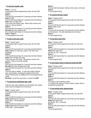
![Vandal Resistant Piezo Keypads
CM-626S and CM-634 Series
Installation Instructions
MOUNTING
Drill mounting holes using template provided
Connect keypad using wiring
WIRING DESCRIPTION
BLUE / BROWN 12 to 24VDC
(BROWN is Positive)
GREY Common
RED N.O.(default) or N.C.,
2A,.. Programmable.
WHITE / PINK Interior switch input (Dry
contact only!)
GREEN Earth
NOTE:
1. For inductive loads such as electric strikes and
electromagnetic locks, the enclosed varistor
must be connected in parallel with the load, at
the load terminals and not in the keypad.
2. Ensure power supply is of correct rating, taking
into account the current requirements of the
locking items and accessories.
3. The interior switch input is via a dry contact
between the White & Orange wires. The door
strike will activate for the time programmed into
the system. This input is disabled during
programming and latch mode.
LED EXPLAINATION
GREEN LED: Relay activated
RED LED Normal Operation
3 sec. ON = Wrong Code Entry
Programming Mode:
Fast flashing = Programming
functions
Slow flashing = Programming
stand-by
Very Fast flashing = Erasing all
user codes
TESTING THE KEYPAD
Apply power to the keypad:
The keypad’s buzzer will sound briefly, the red LED will
illuminate briefly. Initialisation is now complete, with a
default master code of 1-2-3-4 and 5-second open door.
Enter the master code: [1 2 3 4 #]:
The Door Relay changes its contacts for 5 sec. The
Green LED will light up for 5 seconds.
Repeat this step 2 or 3 times.
If the master code is entered incorrectly, the Red LED
illuminates for 3 seconds.
Re-enter the Code as soon as the Red LED goes OFF.
PROGRAMMING THE KEYPAD
Enter **1 2 3 4**
The keypad enters programming mode, the red LED
flashes.
If no further information is added, the unit will revert to
normal operation after a 15 second delay.
To exit programming press #
There are six programming options:
1. Set new master code
2. Set new user code
3. Erase a user code
4. Erase all user codes
5. Set door open time (1-99 seconds)
6. Set output to latch option
Do not insert security plugs into fixing
holes until all installation and testing has
been completed!! These items require
drilling out and cannot be re-fitted.
It is good practice to change the factory
default master code. There is no way to
recover the new Master Code, if it is lost or
forgotten however, the unit can be easily reset
to Factory Presets and re-programmed again.](https://image.slidesharecdn.com/626s-150730151611-lva1-app6891/85/Camden-626S-Instruction-Manual-1-320.jpg)
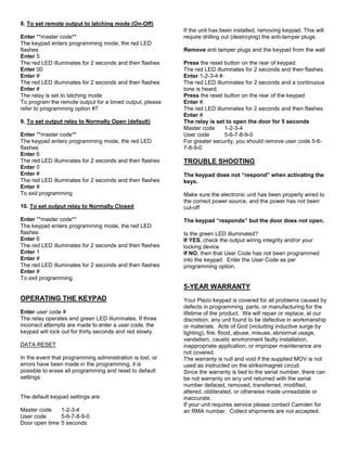
![Vandal Resistant Piezo Keypads
CM-626S and CM-634 Series
Installation Instructions
MOUNTING
Drill mounting holes using template provided
Connect keypad using wiring
WIRING DESCRIPTION
BLUE / BROWN 12 to 24VDC
(BROWN is Positive)
GREY Common
RED N.O.(default) or N.C.,
2A,.. Programmable.
WHITE / PINK Interior switch input (Dry
contact only!)
GREEN Earth
NOTE:
1. For inductive loads such as electric strikes and
electromagnetic locks, the enclosed varistor
must be connected in parallel with the load, at
the load terminals and not in the keypad.
2. Ensure power supply is of correct rating, taking
into account the current requirements of the
locking items and accessories.
3. The interior switch input is via a dry contact
between the White & Orange wires. The door
strike will activate for the time programmed into
the system. This input is disabled during
programming and latch mode.
LED EXPLAINATION
GREEN LED: Relay activated
RED LED Normal Operation
3 sec. ON = Wrong Code Entry
Programming Mode:
Fast flashing = Programming
functions
Slow flashing = Programming
stand-by
Very Fast flashing = Erasing all
user codes
TESTING THE KEYPAD
Apply power to the keypad:
The keypad’s buzzer will sound briefly, the red LED will
illuminate briefly. Initialisation is now complete, with a
default master code of 1-2-3-4 and 5-second open door.
Enter the master code: [1 2 3 4 #]:
The Door Relay changes its contacts for 5 sec. The
Green LED will light up for 5 seconds.
Repeat this step 2 or 3 times.
If the master code is entered incorrectly, the Red LED
illuminates for 3 seconds.
Re-enter the Code as soon as the Red LED goes OFF.
PROGRAMMING THE KEYPAD
Enter **1 2 3 4**
The keypad enters programming mode, the red LED
flashes.
If no further information is added, the unit will revert to
normal operation after a 15 second delay.
To exit programming press #
There are six programming options:
1. Set new master code
2. Set new user code
3. Erase a user code
4. Erase all user codes
5. Set door open time (1-99 seconds)
6. Set output to latch option
Do not insert security plugs into fixing
holes until all installation and testing has
been completed!! These items require
drilling out and cannot be re-fitted.
It is good practice to change the factory
default master code. There is no way to
recover the new Master Code, if it is lost or
forgotten however, the unit can be easily reset
to Factory Presets and re-programmed again.](https://image.slidesharecdn.com/626s-150730151611-lva1-app6891/75/Camden-626S-Instruction-Manual-1-2048.jpg)

This document provides installation and programming instructions for vandal resistant piezo keypads models CM-626S and CM-634. It describes how to mount the keypad, connect the wiring, and program settings like codes, relay behavior, and door open time. The keypad can be reset to factory defaults by pressing the reset button while entering the default master code. It comes with a 5-year warranty against defects.


![[AWSマイスターシリーズ] AWS Billingについて](https://cdn.slidesharecdn.com/ss_thumbnails/20140226aws-meister-regenerate-billing-public-140303002826-phpapp01-thumbnail.jpg?width=640&height=640&fit=bounds)


