
Recommended
More Related Content
Similar to C102-metro design work in Mumbai-mah.pptx
Similar to C102-metro design work in Mumbai-mah.pptx (20)
Recently uploaded
Recently uploaded (20)
C102-metro design work in Mumbai-mah.pptx
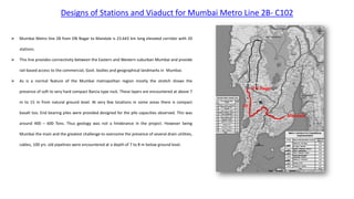
- 1. Designs of Stations and Viaduct for Mumbai Metro Line 2B- C102 Mumbai Metro line 2B from DN Nagar to Mandale is 23.643 km long elevated corridor with 20 stations. This line provides connectivity between the Eastern and Western suburban Mumbai and provide rail-based access to the commercial, Govt. bodies and geographical landmarks in Mumbai. As is a normal feature of the Mumbai metropolitan region mostly the stretch shows the presence of soft to very hard compact Barcia type rock. These layers are encountered at above 7 m to 15 m from natural ground level. At very few locations in some areas there is compact basalt too. End bearing piles were provided designed for the pile capacities observed. This was around 400 – 600 Tons. Thus geology was not a hinderance in the project. However being Mumbai the main and the greatest challenge to overcome the presence of several drain utilities, cables, 100 yrs. old pipelines were encountered at a depth of 7 to 8 m below ground level.
- 2. Designs of Stations and Viaduct for Mumbai Metro Line 2B- C102 Package C102 is having 5.8 Km long stretch consists of 4.94 km long viaduct and 5 elevated stations namely MTNL SG Barve Kurla east Eastern express highway Chembur station Viaduct portion consists of 75m+125m+70m Balanced cantilever span 61 m semi-through plate girder (Obligatory span) 55 m steel plate girder over Bullet train crossing span 55 m steel plate girder over central railway crossing span. For remaining portion of viaduct pre-tensioned U girder have proposed. 27 17 17 17 END OF PROJ ECT C102 28 28 28 25 30 20 25 28 28 16.5 73.35 0 41 186m MTN L MET RO STA TION END OF PRO JEC T C10 1 STA RT OF PRO JEC T C10 2 CH : 46+ 860 .384 HPCL LINE HPCL LINE HPCL LINE HPCL LINE HPCL LINE HPCL LINE HPCL LINE HPCL LINE HPCL LINE 28 28 28 28 17 28 28 25 20 20 P72 2 P73 3 NO CON STR UCT ION ZON E NO CON STR UCT ION ZON E 27 25 25 25 25 21.78 1 16. 5 P2/M P55 7 MATC H LINE-7 MAT CH LINE -8 MA TC H LIN E-9 MATC H LINE-1 0 1.5 186 m CH EM BU R STA TIO N 26.6 44 28 28 21 21 21 25 16. 5 17 17 17 17 17 17 17 17 17 186m EEH STA TION 25 25 29.100 28 28 1.926 14.3 12.15 8.12 10.44 8.12 12.15 14.72 45 27 27 13.678 28 31 31 31 25 28 24 55 ROW ROW ROW ROW ROW ROW ROW ROW ROW ROW ROW ROW ROW ROW ROW ROW ROW ROW ROW ROW ROW ROW ROW ROW ROW ROW ROW ROW ROW ROW ROW ROW ROW ROW ROW ROW ROW ROW ROW ROW ROW ROW ROW ROW ROW ROW ROW ROW ROW ROW ROW ROW ROW ROW ROW ROW ROW ROW ROW ROW ROW ROW ROW ROW ROW ROW ROW ROW ROW ROW ROW ROW ROW ROW ROW ROW ROW ROW ROW ROW ROW ROW ROW ROW ROW ROW ROW ROW ROW ROW ROW ROW ROW ROW ROW ROW ROW ROW ROW ROW ROW ROW ROW ROW ROW ROW ROW ROW ROW ROW ROW ROW ROW ROW ROW ROW ROW ROW ROW ROW ROW ROW ROW ROW ROW ROW ROW ROW ROW ROW ROW ROW ROW ROW ROW ROW ROW ROW ROW ROW ROW ROW ROW ROW ROW ROW ROW ROW ROW ROW ROW ROW ROW ROW ROW ROW ROW ROW ROW ROW ROW ROW ROW ROW ROW ROW ROW ROW ROW ROW ROW ROW ROW ROW ROW ROW ROW ROW ROW ROW ROW ROW ROW ROW ROW ROW ROW ROW ROW ROW ROW ROW ROW ROW ROW ROW ROW ROW ROW ROW ROW ROW ROW ROW ROW ROW ROW ROW ROW ROW ROW ROW ROW ROW ROW ROW ROW ROW ROW ROW ROW ROW ROW ROW ROW ROW ROW ROW ROW ROW ROW ROW ROW ROW ROW ROW ROW ROW ROW ROW ROW ROW ROW ROW ROW ROW ROW ROW ROW ROW ROW ROW ROW ROW ROW ROW ROW ROW ROW ROW ROW ROW ROW ROW ROW ROW ROW ROW ROW ROW ROW ROW ROW ROW ROW ROW ROW ROW ROW ROW ROW ROW ROW ROW ROW ROW ROW ROW ROW ROW ROW ROW ROW ROW ROW ROW ROW ROW ROW ROW ROW ROW ROW ROW ROW ROW ROW ROW ROW ROW ROW ROW ROW ROW ROW ROW ROW ROW ROW ROW ROW ROW ROW ROW ROW ROW ROW ROW 27 27 27 25 25 25 25 25 25 25 25 25 25 25 MA TC H LIN E- 1 MA TC H LIN E-2 MATCH LINE-3 MATC H LINE- 4 MAT CH LINE -5 28 28 28 27 31 0.1 0.5 1 47° 28 31 25 22 45 15 186m KURLA EAST STATION 25 25 15.511 37 23 42 25 25 25 25 25 25 0.6 1 0.6 1.2 5 1.2 1.5 1 P614 P625 P7 47 P7 58 67° 22 22 15 25 27.5 34 28 25 20.53 9 25 25 25 25 25 25 25 25 25 25 25 25 25 25 25 25 25 25 0.8 0.5 25 17 37 25 25 25 25 22 22 28 19.88 5 41.545 28 25 25 25 25 25 25 25 25 25 25 25 25 25 19.414 P665 P676 0.4 25 25 25 13.622 25 25 25 25 25 17 17 17 17 17 17 16.5 16.5 18.61 4 17 22.00 21.8 42 16.5 CH.52 +730.1 04 (M) E 27910 5.4855 38 N 21079 06.917 021 16.5 17 17 17 13.8 12 0.5 19.201 25 25 25 25 25 25 1.5 1.0 23.919 186m S. G. BARVE MARG STATION 28 25 16.5 17 17 17 17 17 17 17 17 17 16.5 25 19.987 17 17 17 STA RT OF PLAT FOR M CH: 46+8 60.38 4 END OF PLA TFOR M CH: 47+0 46.38 4 START OF PLATFORM CH: 48+564.910 END OF PLATF ORM CH: 48+75 0.910 START OF PLATFORM CH: 49+829.104 END OF PLATFORM CH: 50+030.104 STA RT OF PLA TFO RM CH: 51+1 86.8 32 END OF PLA TFO RM CH: 51+3 72.8 32 STA RT OF PLA TFO RM CH : 51+ 731 .644 EN D OF PLA TFO RM CH : 51+ 917 .644 P615 B P616 C P617 D P618 E P619 F P620 G 17 17 17 17 17 17 17 17 17 16.5 16.5 0.7 5.70 2 5.03 45.8 72 P621 H P622 J P623 K P624 L 27 27 20 20 20 25 55 50 2 1 25 72. 759 120 68.4 82 15.7 5 19.5 15.7 5 25 17 E 275 839 .964 581 N 210 992 4.71 101 6 CH. 46+ 953 .384 (M) MTN L ME TRO (ST N.) E 277042 .882576 N 211034 5.83246 1 CH.48+ 657.91 0 (M) S. G. BARVE MARG (STN.) E 277616.327 779 N 2109410.50 3245 CH.49+937 .104 (M) KURLA EAST (STN.) E 277 773 .71 781 4 N 210 830 8.0 584 94 CH :51 +27 9.8 32 (M) EE H ST AT ION E 27 82 39 .66 31 82 N 21 08 14 2.5 98 29 4 CH :51 +8 24 .64 4 (M ) CH EM BU R ST AT ION 46+8 00 46+8 20 46+8 40 46+8 60 46+8 80 46+9 00 46+9 20 46+9 40 46+9 60 46+9 80 47+0 00 47+0 20 47+0 40 47+0 60 47+0 80 47+10 0 47+120 47+140 47+160 47+180 47+200 47+220 47+24 0 47+2 60 47+ 280 47+ 300 47+ 320 47+ 340 47+ 360 47+ 380 47+ 400 47+ 420 47+4 40 47+46 0 47+480 47+500 47+520 47+540 47+560 47+580 47+600 47+62 0 47+6 40 47+6 60 47+ 680 47+ 700 47+ 720 47+ 740 47+ 760 47+ 780 47+ 800 47+ 820 47+ 840 47+ 860 47+ 880 47+ 900 47+ 920 47+ 940 47+ 960 47+ 980 48+ 000 48+ 020 48+ 040 48+0 60 48+08 0 48+100 48+120 48+140 48+160 48+180 48+200 48+220 48+240 48+260 48+280 48+300 48+320 48+340 48+360 48+380 48+400 48+420 48+440 48+460 48+480 48+500 48+520 48+540 48+560 48+580 48+600 48+620 48+640 48+660 48+680 48+700 48+720 48+740 48+760 48+780 48+800 48+820 48+840 48+860 48+880 48+900 48+920 48+940 48+960 48+980 49+000 49+020 49+040 49+060 49+080 49+100 49+120 49+140 49+160 49+180 49+200 49+220 49+240 49+260 49+280 49+300 49+320 49+340 49+360 49+38 0 49+40 0 49+42 0 49+44 0 49+46 0 49+4 80 49+5 00 49+5 20 49+5 40 49+5 60 49+5 80 49+6 00 49+ 620 49+ 640 49+ 660 49+ 680 49+7 00 49+720 49+740 49+760 49+780 49+800 49+820 49+840 49+860 49+880 49+900 49+920 49+940 49+960 49+980 50+000 50+020 50+040 50+060 50+080 50+100 50+120 50+140 50+160 50+180 50+200 50+220 50+240 50+260 50+280 50+300 50+320 50+340 50+360 50+380 50+400 50+4 20 50+ 440 50+ 460 50+ 480 50+ 500 50+5 20 50+54 0 50+56 0 50+58 0 50+60 0 50+62 0 50+64 0 50+66 0 50+68 0 50+70 0 50+72 0 50+74 0 50+76 0 50+78 0 50+8 00 50+8 20 50+8 40 50+8 60 50+8 80 50+90 0 50+92 0 50+94 0 50+96 0 50+98 0 51+00 0 51+02 0 51+04 0 51+06 0 51+08 0 51+10 0 51+12 0 51+14 0 51+16 0 51+18 0 51+2 00 51+2 20 51+2 40 51+2 60 51+2 80 51+3 00 51+3 20 51+3 40 51+3 60 51+3 80 51+40 0 51+420 51+440 51+460 51+480 51+500 51+5 20 51+ 540 51+ 560 51+ 580 51+ 600 51+ 620 51+ 640 51+ 660 51+ 680 51+ 700 51+ 720 51+ 740 51+ 760 51+ 780 51+8 00 51+ 820 51+ 840 51+ 860 51+ 880 51+ 900 51+ 920 51+ 940 51+ 960 51+ 980 52+0 00 52+0 20 52+0 40 52+0 60 52+0 80 52+10 0 52+12 0 52+14 0 52+160 52+180 52+200 52+220 52+240 52+260 52+280 52+300 52+320 52+340 52+360 52+380 52+400 52+420 52+440 52+460 52+480 52+500 52+520 52+540 52+560 52+580 52+600 52+620 52+640 52+660 52+680 52+700 52+720 52+740 52+760 52+780 52+800 52+820 52+840 52+860 52+880 52+900 52+920 TS: 47+0 63.72 0 SC: 47+128.7 20 CS: 47+ 278 .049 SP I: 47+ 343 .04 9 SC: 47+ 408 .049 CS: 47+61 9.982 ST: 47+6 84.9 82 TS: 47+9 46.1 98 SC : 48+ 011 .198 CS: 48+103.33 5 ST: 48+168.335 TS: 48+251.665 SC: 48+291.665 CS: 48+339.980 ST: 48+379.980 TS: 48+538.375 SC: 48+563.375 CS: 48+781 .473 SPI: 48+806 .473 SC: 48+856.47 3 CS: 48+931.384 ST: 48+981.3 84 TS: 49+102.3 72 SC: 49+132.3 72 CS: 49+190 .524 ST: 49+220 .524 TS: 49+370 .403 SC: 49+39 5.403 CS: 49+45 0.538 ST: 49+47 5.538 TS: 49+55 0.998 SC: 49+ 615 .998 CS: 49+712 .223 ST: 49+777.223 TS: 50+046.398 SC: 50+086.398 CS: 50+185.41 2 ST: 50+225 .412 TS: 50+308 .690 SC: 50+363.690 CS: 50+ 498. 542 SPI: 50+553 .542 SC: 50+59 3.542 CS: 50+61 9.541 ST: 50+65 9.541 TS: 50+74 4.484 SC: 50+76 9.484 CS: 50+80 2.743 SPI: 50+8 27.74 3 SC: 50+8 52.74 3 CS: 50+91 9.400 ST: 50+94 4.400 BVC: 47+146.986 EVC: 47+174.536 BVC : 47+6 88.0 70 EVC : 47+7 22.3 92 BVC : 47+9 06.9 24 EVC : 47+9 45.0 67 BVC: 48+195.070 EVC: 48+230.647 BVC: 48+419.324 EVC: 48+447.364 BVC: 48+870.901 EVC: 48+896.852 BVC: 49+148. 340 EVC: 49+174 .291 BVC: 49+51 4.142 EVC: 49+54 2.397 BVC : 49+6 82.2 41 EVC: 49+71 0.497 BVC: 50+089.798 EVC: 50+115.944 BVC: 50+228 .142 EVC: 50+256 .795 BVC: 50+364.619 EVC: 50+398.5 01 BVC: 50+68 3.014 EVC: 50+72 8.177 BVC : 51+1 18.53 0 EVC : 51+1 50.31 8 BVC: 51+419 .410 EVC: 51+461.364 BV C: 51+ 666 .01 8 EV C: 51+ 707 .97 2 BVC : 52+ 041. 880 EVC : 52+0 79.3 68 BVC: 52+278 .421 EVC: 52+315 .907 BVC: 52+437 .177 EVC: 52+473 .046 BVC: 52+678 .124 EVC: 52+713 .993 PVI: 47+160.761 PVI: 47+7 05.2 31 PVI: 47+9 25.9 95 PVI: 48+212.859 PVI: 48+433.344 PVI: 48+883.876 PVI: 49+161 .315 PVI: 49+52 8.270 PVI: 49+6 96.36 9 PVI: 50+102.871 PVI: 50+242 .468 PVI: 50+381.560 PVI: 50+70 5.598 PVI: 51+13 4.422 PVI: 51+440.391 PV I: 51+ 686 .99 1 PVI: 52+ 060. 627 PVI: 52+297 .161 PVI: 52+455 .113 PVI: 52+696 .057 SRJ (1 IN 9 R=300) 52+336.0 37 EoP = 52+730.1 04 52+714 .312 CA-07 DIAMON D GARDEN STATION 52+822.3 12 TS: 51+15 2.525 SC: 51+19 2.525 CS: 51+2 22.92 3 ST: 51+2 62.92 3 TS: 51+3 74.37 7 SC: 51+414 .377 CS: 51+5 31.2 87 ST: 51+ 571 .287 TS: 51+ 631 .095 SC: 51+ 661 .095 CS: 51+7 70.1 11 SPI: 51+8 00.1 11 SC: 51+8 30.1 11 CS: 51+ 867 .097 ST: 51+ 897 .097 TS: 51+ 927 .644 SC: 51+ 982. 644 CS: 52+171 .631 ST: 52+226.6 31 TS: 52+481.2 03 SC: 52+506.2 03 CS: 52+544.2 59 SPI: 52+569.2 59 SC: 52+594.2 59 CS: 52+645.9 81 ST: 52+670.9 81 SRJ (1 IN 9 R=300) 52+416.0 37 MTNL Station S G Barve Station Kurla East Station EEH Station Chembur Station Balanced cantilever span at Mithi river Line 4 interface Bullet train crossing (No construction zone) Alignment of Line 2B
- 3. Designs of Stations and Viaduct for Mumbai Metro Line 2B Longitudinal Elevation- MTNL station Typical Cross Section Key features: Length = 180 m Width = 21.6 m Foundation = Pile foundation Dia. Of piles = 1000 mm Type of strata= Slightly weathered Bracia Length of piles proposed as per strata availability = 12 m Max. Pile capacity = 500 MT (for 3D socketing) Substructure: Pier – RCC cast in situ Concourse arm – Precast post tensioned Platform arm – Precast post tensioned Superstructure: Concourse & platform girders – RCC girders Deck slab – RCC 150 mm Precast pretensioned U Girders
- 4. Designs of Stations and Viaduct for Mumbai Metro Line 2B Design philosophy : • Span arrangement of station is 17 m x 4 span continuous unit + 17 m x 3 span continuous unit + 17 m x 4 span continuous unit • Foundations have proposed as pile foundations with 1000 /1200 mm dia bored cast-in-situ piles at not more than 15 m length of piles since rock is available at depth of 10 to 12 m • Generally, 8 to 10 piles are sufficient since pile capacity of 500 MT is available with 2D / 3D socketing in rock • Entire station is modelled in STAAD and foundations idealised by applying soil springs as per IS: 2911 (Part 1/Sec 2). • Response spectrum analysis performed separately to take the effect of seismic force • Expansion joint between two continuous units is maintained 50 mm to satisfy pounding effect. • Continuity maintained by providing without bearing structures which is main advantages to avoid repair/replacement of bearing in future. • Since these stations have placed on median of exiting road, size of excavation for pilecap is restricted to max 7 to 8 m in transverse direction which is big challenge for arrangement of piles in such way that there shall not be any eccentricity in the pile group and sometimes it is very severe when there are utilizes encountered on site. • Concourse arm have been casted in 3 pieces, middle portion have casted as hammer head for pier cast-in-situ and remaining portion on either sides casted in casting yard and launched as per schedule of construction by introducing a stitching joint of 600 mm. • Platform arm have been casted in single piece of 21 m and launched at location by taking temporary support from already casted concourse arms. • Concourse and platform floor girders are RCC precast girders of varying lengths from 16.5 m to 19 m and at the support of these girders 32 mm dia pins have provided to achieve continuity. • Design of all the components for each pier locations have performed separately because of loading situation and arrangement of floor components such as staircase, lifts, escalators as per architectural requirements. So the design efforts are appreciable for each components. • For movement of metro train , precast pretensioned ‘U” girder have proposed with varying lengths as per situation. DIRECTION TRAFFIC Idealised STAAD Model
- 5. Designs of Stations and Viaduct for Mumbai Metro Line 2B Construction Methodology Stage- 1 : Pier arm (Hammer head) to be cast 1800mm from pier face with dowel bars on either side Stage- 2 : Precast unit with dowels to be left for balance 600mm casting portion Stage- 3 : Casting of 600mm cast-in-situ stitch portion & prestressing of pier arm This component supports concourse floor girders, lifts, staircase, escalator & respecting rooms over there as per architectural requirements. It is cantilever component with total length is 22.1 m and width at top is 1.7 m & width at bottom is 3.3 m. Ledges (0.8 m x 0.5 m) have provided at bottom to support floor girders. It is cast in three pieces as 6.6 m cast in situ along with pier and 7.15 m precast segment stitched together on either side with 0.6 m stitching joint. Concourse Arm Typical dimensions of concourse arm
- 6. Designs of Stations and Viaduct for Mumbai Metro Line 2B Concourse arm: • The analysis has been done using MIDAS Civil analysis software. • Concourse Pier arm is modelled in MIDAS as line model, point loads and moments are applied at girder resting positions. • The loads are taken from STAAD file used for Pile foundation analysis and designs. • Cable profile is assigned for pier arm elements with prestressing loads. Stress check is presented herewith with reference to MIDAS Typical section of Concourse arm Cable profile of Concourse arm Arrangement of cables Idealised MIDAS Model For this section, M60 grade of concrete adopted, and T 15 strands used. Above section have designed to satisfy maximum compressive stress in concrete of 24 Mpa with no tension at service condition and max. 1 Mpa tension during construction conditions. T32-4 nos at each girder location have provided for horizontal temperature forces due to continuity action.
- 7. Designs of Stations and Viaduct for Mumbai Metro Line 2B This component supports ‘U’ girders, platform floor girders, lifts, staircase, escalator as per architectural requirements. It is cantilever component with total length is 22.6 m and varying width & depth below U girder & floor girder locations. It is casted in single piece as precast segment & stitched together at top of pier. Platform Arm Typical dimensions of platform arm
- 8. Designs of Stations and Viaduct for Mumbai Metro Line 2B Platform Arm Idealised MIDAS Model For this section, M60 grade of concrete adopted, and T 15 strands used. Above section have designed to satisfy maximum compressive stress in concrete of 24 Mpa with no tension at service condition and max. 1 Mpa tension during construction conditions. Typical cable profile of platform arm
- 9. Designs of Stations and Viaduct for Mumbai Metro Line 2B Concourse floor girders These girders analysed in STAAD and checked for its ultimate bending capacity and shear capacity using ULS combinations in IRS. The serviceability limit state design for stress and crack width checked for different sections of girders.
- 10. Designs of Stations and Viaduct for Mumbai Metro Line 2B Eastern Express Highway Station Height of this station more than earlier station to satisfy crossing of a flyover on eastern express highway and another metro line 4 and so called it is interface of line 4 & line 2B of Mumbai metro network. Because of this reason EEH station is having 3 levels as lower concourse level, upper concourse level & platform level. All other design philosophy is same as discussed in the above. Because of higher loading it is required to provide 10 piles of 1200 mm diameter. This EEH station have extended by two spans for to connect with line 4 station. At some pier locations width of station is increased to provide staircase / escalators and then it is required provide cantilever concourse arm of 26 m. Typical section of EEH Station
- 11. Designs of Stations and Viaduct for Mumbai Metro Line 2B Chembur Station LP-2 This is having slight curvature and it is also highted station and reason is that at nearby there is crossing to elevated viaduct of monorail. Plan & Elevation of Chembur Station
- 12. Designs of Stations and Viaduct for Mumbai Metro Line 2B Airport This station is different than other stations because it is single story over 32 m long portals with 3 columns to each portal. Span arrangement is not regular because of cross nallah and curvature to road below station. This station is having height restrictions because it is under air funnel zone of Mumbai international airport. S G Barve Marg Station >>>CST ROAD>>> <<<CST ROAD<<< FOB MEDIAN Layout of S G Barve Marg Station
- 13. Designs of Stations and Viaduct for Mumbai Metro Line 2B S G Barve Marg Station At each pier location position of U girder changes because of curvature and accordingly design of portal is the challenge. Construction of portal is planned in such way that maximum possible portion should be precast and remaining portion should be cast in-situ to avoid traffic block and site suitability. Lengths of precast portion and cast-situ portion is varying at every pier location, so their design efforts are appreciable. Typical cross section of S G Barve Marg Station
- 14. Designs of Stations and Viaduct for Mumbai Metro Line 2B For entire viaduct precast pretensioned U girder of varying lengths from 13 m to 28 m proposed except at some special spans & at obligatory span locations. Precast pre tensioned U girders proposed because of its following advantages. 1. It is light weight. 2. It is easy to handle and launch over required positions within minimum time. 3. No anchorage blocks are required. 4. No separate deck slab is required to cast. These U girders are applicable to curvature portion where radius is more than 250 m otherwise I girder and deck slab can be provided to achieve that curvature.
- 15. Designs of Stations and Viaduct for Mumbai Metro Line 2B At bullet train crossing, it is mandatory provide high span of 55 m steel plate girder because of “No construction zone” of 35 m at crossing. Bullet train have proposed 20 m below natural ground level and again it is required to provide piles at the level of bullet train tunnel. This span is having prefabricated steel plate girders and cast in situ RCC deck. At central railway crossing, 61 m + 55 m semi through steel girder proposed. At this location availability of minimum clearance over rail level semi through steel girder have proposed. P601 P602
- 16. Designs of Stations and Viaduct for Mumbai Metro Line 2B Technical Features: The Spans are 75m + 125 m + 70m. Radius of curvature is 210m. Single celled box girder with minimum depth = 3.5m to 6.75m Loading: Metro loading – Double Track Challenges Crosses the Mithi river with a strict mandate of not encroaching the waterway at all! Dense population at both ends. Filthy water condition and working not possible with human interface. At Mithi river crossing, balanced cantilever of 75 + 125m + 70 m have proposed Idealised MIDAS Model Plan & Elevation of Balanced cantilever span