The document discusses the dispersion analysis in optical fibers, specifically focusing on single-mode and multimode fibers. It explains different types of dispersion such as material and waveguide dispersion, their effects on signal transmission, and methodologies for measuring dispersion. The results indicate differences in chromatic dispersion between single-mode and multimode fibers, highlighting the complexities of managing dispersion in optical communications.
![Journal of Science and Technology
ISSN: 2456-5660 Volume 2, Issue 01 (Jan –Feb 2017)
www.jst.org.in DOI:https://doi.org/10.46243/jst.2017.v2.i01.pp59 - 65
Page | 59
Published by: Longman Publishers www.jst.org.in
Dispersion Analysis in Single Mode and Multimode Fiber
Mahindra Umbarkar
Electronics and Telecommunication
Government Polytechnic
Jalgaon, India
mahindra.umbarkar@gmail.com
To Cite this Article
Mahindra Umbarkar Dispersion Analysis in an Optical Fiber Journal of Science and Technology, Vol. 02, Issue
03,-Jan– Feb 2017, pp59 -65
Article Info
Received: 23-02-2017 Revised: 3-01-2017 Accepted: 12-01-2017 Published: 28-01-2017
Abstract-
A cylindrical-shaped dielectric waveguide is what an optical fibre is. The core cladding interface
confines electromagnetic energy in the form of light within its surface and directs light through a
number of internal reflections if the angle of incidence is larger than the critical angle c. The
dispersion of the transmitted optical signal causes distortion in both digital and analogue
transmission across optical fibres. When optical fibre transmission is widely employed and some
sort of digital modulation is applied, dispersion mechanisms inside the fibre cause the
transmitted light pulses to broaden as they move along the channel.
Keywords- Dispersion; singlemode fiber; multimode fiber; light; optical fiber;
Introduction-
Dispersion is the process through which a light pulse spreads out over time as it moves down the
fibre. Dispersion in optical fibre can take the forms of model dispersion, material dispersion, and
waveguide dispersion. Material dispersion results from the refractive index of fibre optic
materials changing with wavelength. Higher indexes cause light to move more slowly.
Waveguide dispersion results from light being split between the waveguide's core and cladding.
[6]
Similar to attenuation, dispersion shortens the distance a signal must travel through optical
fibres. Dispersion, as opposed to attenuation, distorts the signal rather than making it weaker. For
example, a pulse with duration of one nanosecond at the transmitter will have duration of 10
nanoseconds at the receiver. Signals are not properly received and decoded as a result. [6]](https://image.slidesharecdn.com/dispersionanalysisinopticalfiber11-241209124056-bedd7349/75/Dispersion-Analysis-in-Single-Mode-and-Multimode-Fiber-1-2048.jpg)
![Journal of Science and Technology
ISSN: 2456-5660 Volume 2, Issue 01 (Jan –Feb 2017)
www.jst.org.in DOI:https://doi.org/10.46243/jst.2017.v2.i01.pp59 - 65
Page | 60
Published by: Longman Publishers www.jst.org.in
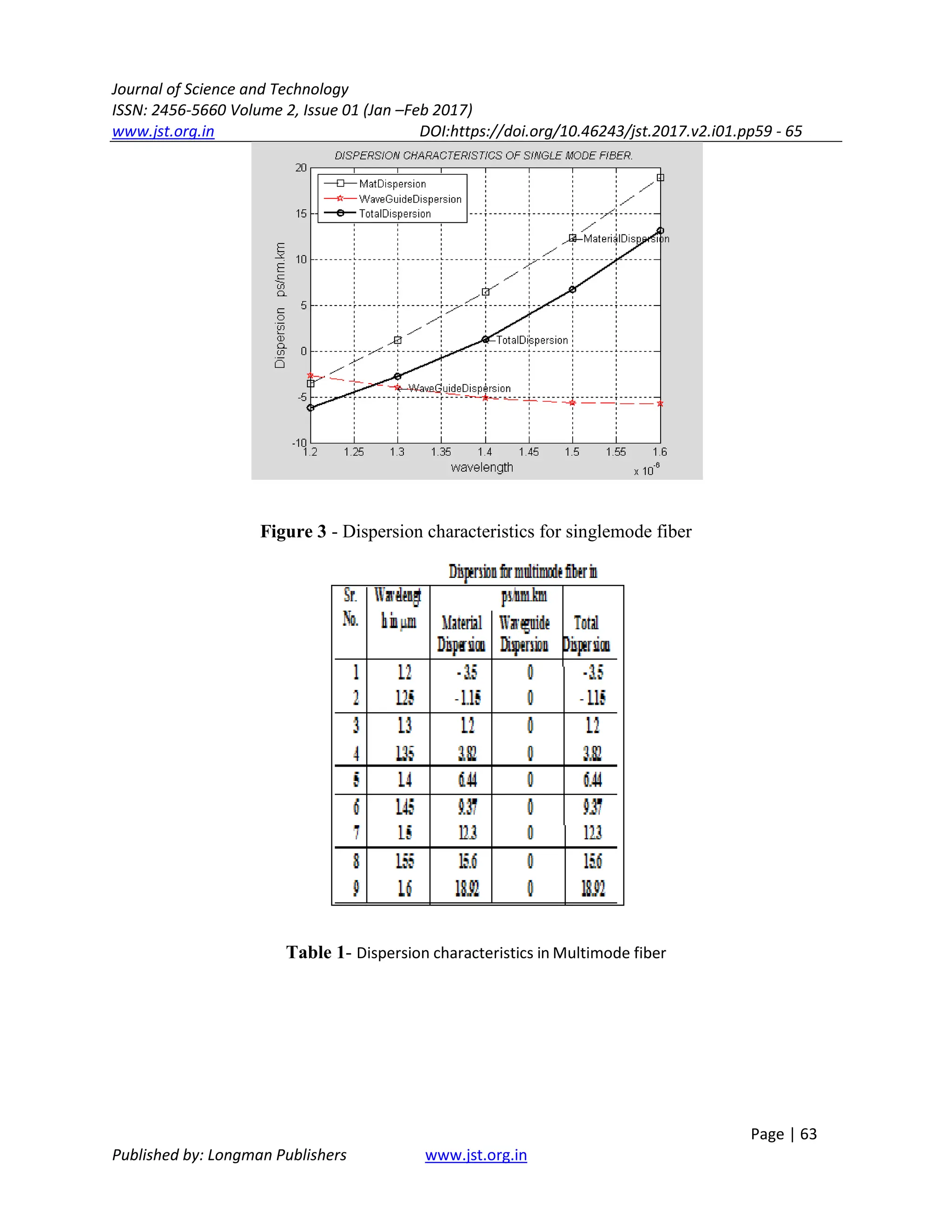
The waveguide dispersion is calculated using a simple curve fitting method. The dispersion
analysis for single mode fibre is carried out by modifying the wavelength in respect to various
types of dispersion, including material dispersion, waveguide dispersion, and total dispersion.
[8,9]
1. Dispersion in optical Fiber-
The process by which an input signal broadens/spreads out as it propagates/travels down the
fibre is referred to as optical fibre dispersion. Modal, chromatic, and polarisation mode
dispersion are the typical types of dispersion in fibre optic cable.
In multimode fibres and other waveguides, a distortion mechanism known as modal
dispersion causes the signal to be spread out in time as a result of the various modes' varying
rates of propagation. As is common knowledge, light rays entering a fibre at various angles of
incidence will follow various routes or modes. As shown below with a step-index multimode
fibre, some of these light rays will travel directly through the fiber's centre (axial mode), while
others will continually bounce off the cladding/core barrier and zigzag their way through the
waveguide.
As far as we are aware, dispersion is a phenomenon that occurs when light travels from one
medium to another. Light of different wavelengths will bend at various angles and cause
dispersion. One common illustration is how a transparent prism would divide white light into a
spectrum of colours, with red light bent at the lowest angle and blue light bent at the greatest
angle. As a result, red light is at the top of the spectrum while blue light is at the bottom. We just
use our secondary understanding of light dispersion to support our explanation [14]. To fully
comprehend dispersion and how it applies to fibre optics, more research must be done. [10]
Figure 1- Modes of optical Fiber
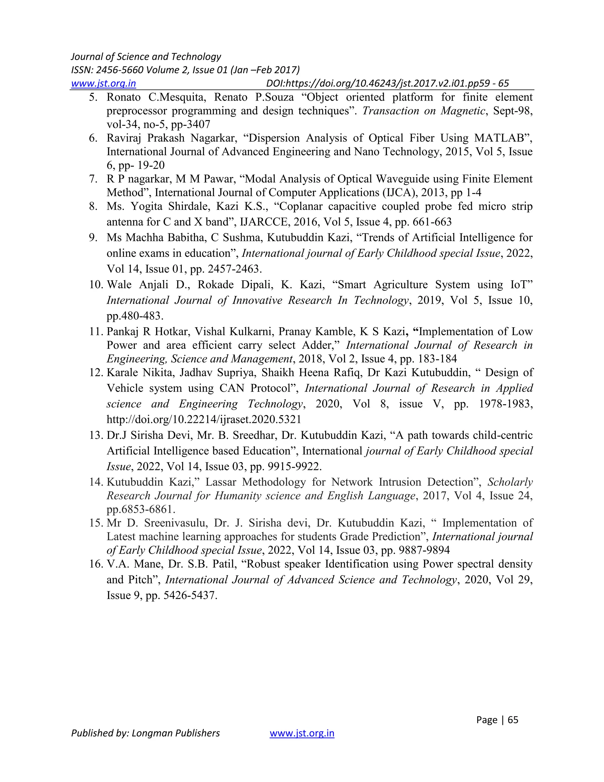
Combining material and waveguide dispersion in a way that results in zero chromatic
dispersion at a desired operating wavelength is a practical application of both (normally between
1530 and 1620 nm). Since material dispersion is typically unpleasant to change due to desirable](https://image.slidesharecdn.com/dispersionanalysisinopticalfiber11-241209124056-bedd7349/75/Dispersion-Analysis-in-Single-Mode-and-Multimode-Fiber-2-2048.jpg)
![Journal of Science and Technology
ISSN: 2456-5660 Volume 2, Issue 01 (Jan –Feb 2017)
www.jst.org.in DOI:https://doi.org/10.46243/jst.2017.v2.i01.pp59 - 65
Page | 61
Published by: Longman Publishers www.jst.org.in
inherent features of the chosen material for optical fibre, this can be accomplished by altering
waveguide dispersion (most likely silica). The following figure illustrates how nonzero
dispersion-shifted fiber's material, waveguide, and chromatic dispersion fluctuate with
wavelength and exhibits zero chromatic dispersion at 1.5 micrometre wavelength.[1,2,7]
The wavelength dependence of the refractive index on the fibre core material is what
leads to material dispersion. Waveguide dispersion happens as a result of the mode propagation
constant's dependency on the signal wavelength, core radius, and difference in refractive indices
between the fibre core and cladding. These two effects may cancel one another out at a specific
frequency, producing a wavelength with nearly zero chromatic dispersion.
Figure 2- Combine waveguide and material dispersion.
The varying speeds of light rays cause a phenomena known as chromatic dispersion,
which is the spreading of a signal across time. The effects of material and waveguide dispersion
combine to create chromatic dispersion.
Additionally, chromatic dispersion need not always be a negative thing. When travelling
through various materials or wavelengths, light moves at varying rates. It is feasible to tailor the
index of refraction profile to create fibres for various uses by causing pulses to either spread out
or compress as they travel along the fibre. For instance, this is how G.652 fibres are made.
2. Measurement Methodology-
Measurements of dispersion reveal how optical signals are distorted as they travel across
optical fibres. The capacity of the fibre for conveying information is constrained by delay](https://image.slidesharecdn.com/dispersionanalysisinopticalfiber11-241209124056-bedd7349/75/Dispersion-Analysis-in-Single-Mode-and-Multimode-Fiber-3-2048.jpg)