Downloaded 1,362 times


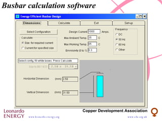

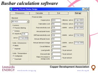


Busbar design involves selecting materials with high electrical conductivity like copper or aluminum. The current rating of busbars depends on factors like working temperature, ambient temperature, heat dissipation via convection and radiation. Busbar size is calculated iteratively to ensure the heat generated by current equals the heat lost to the environment. The most economic size minimizes total material, installation and energy costs over the busbar's lifetime.


