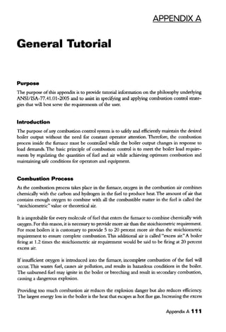
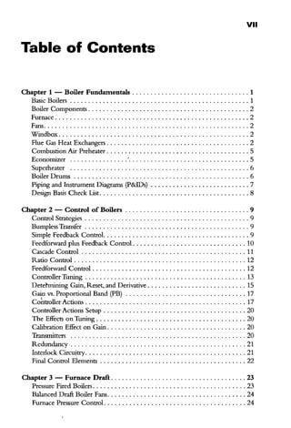
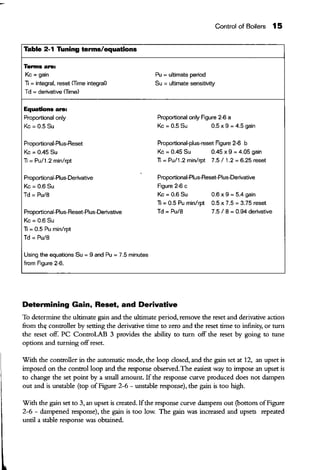
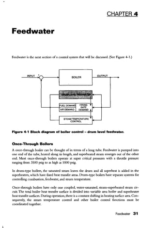
This document provides an introduction to boiler control systems engineering. It begins with an overview of basic boiler components such as the furnace, fans, heat exchangers, drums and piping. It then discusses common control strategies for boilers like feedback control, feedforward control and cascade control. The document provides details on tuning PID controllers and determining control parameters. It is intended to help anyone working with boiler control systems understand the engineering of boiler controls.

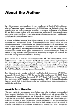


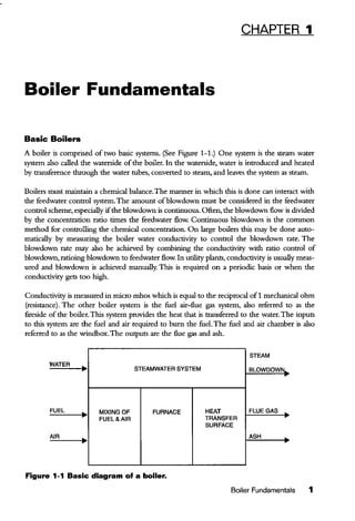
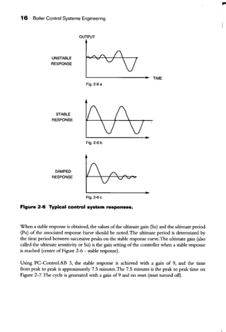
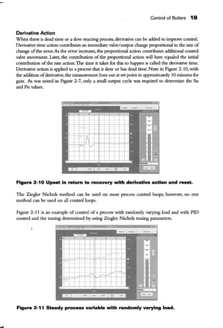
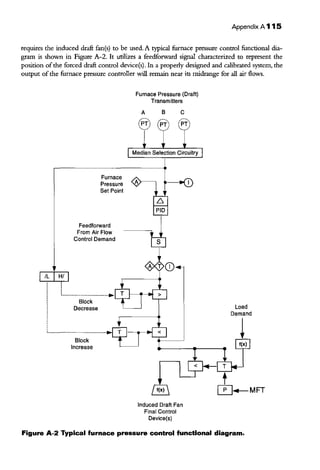
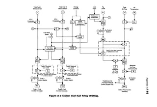
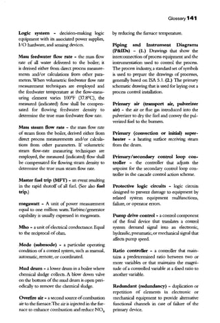
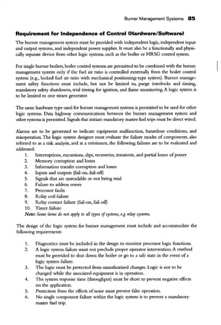
![h(1) < h(2) BECAUSE t(1) < t(2)
t =WATER TEMPERATURE
h =HEIGHT OF WATER COLUMN
MIRRO~---· OPERATOR
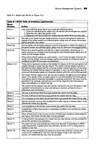
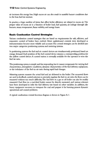
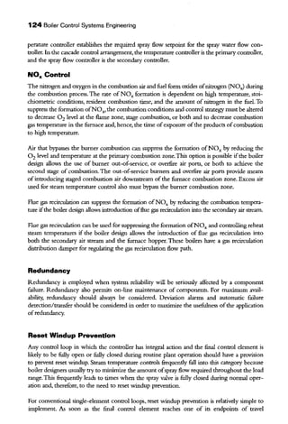
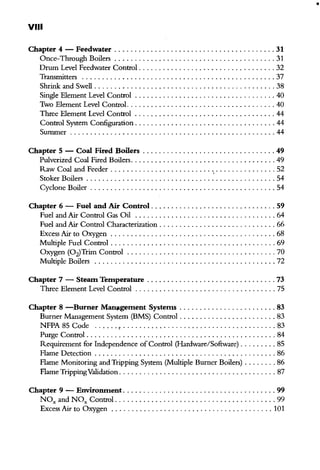
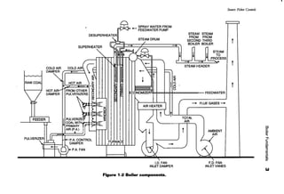
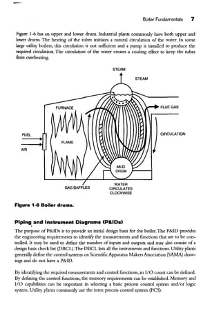
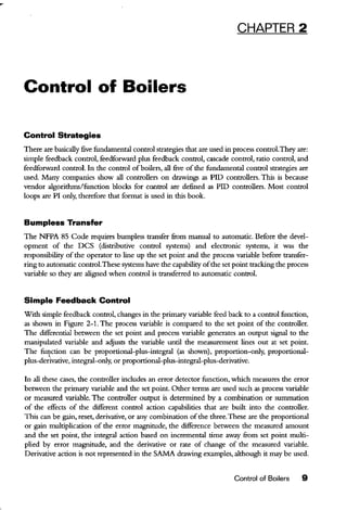
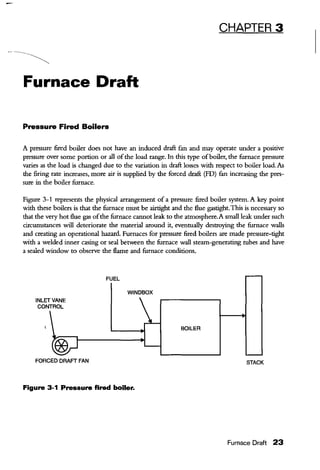
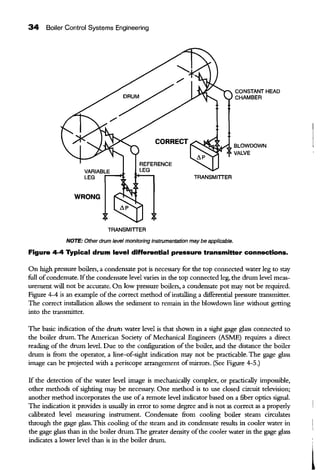
Figure 4-5 Gage glass drum level indication.
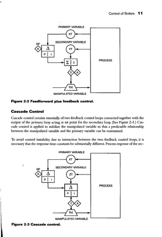
STEAM
h(1)
WATER
h(2)
h (1), h (2), h (3)-
70° WATER COLUMN EQUIVALENT
NET TRANSMITTER PRESSURE DIFFERENTIAL
= h (3)- [h (1) + h(2)]
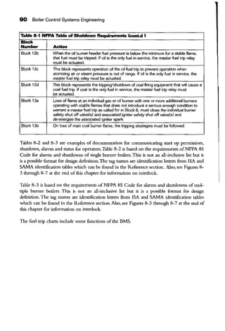
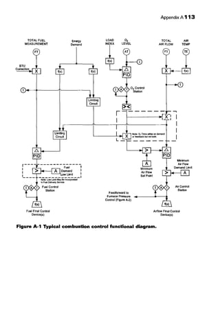
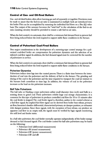
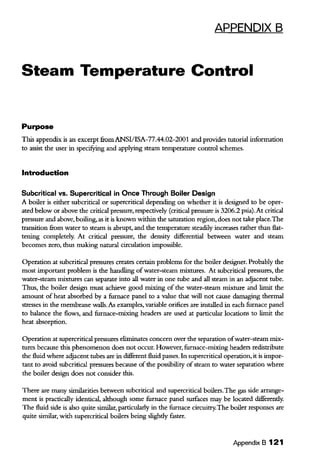
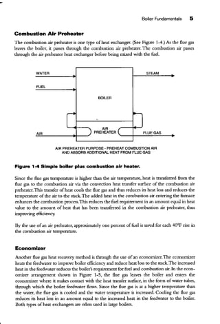
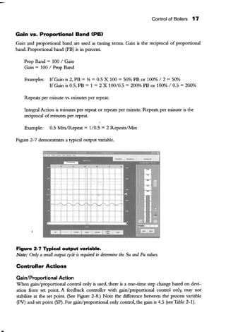
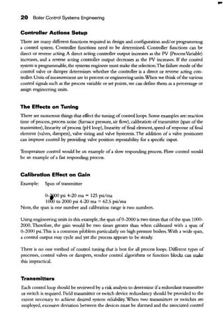
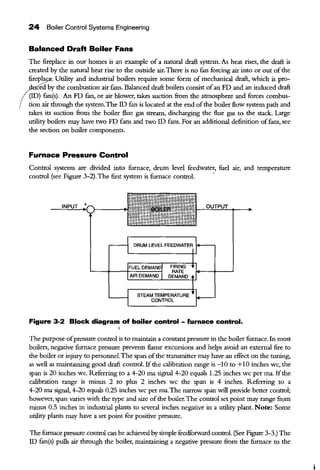
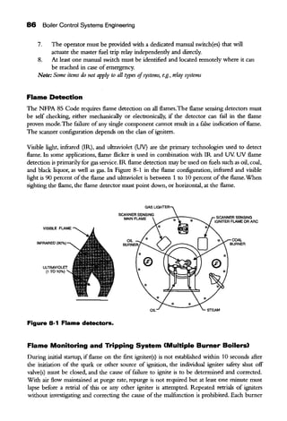
Figure 4-6 Drum level transmitter.
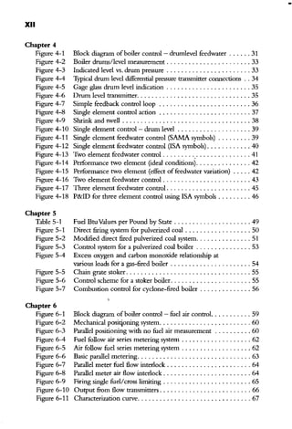
Feedwater 35
t(2)
WATER
CONDENSATE RESERVOIR
Th(3)
1
TRANSMITTER
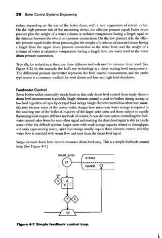
Figure 4-6 is a typical arrangement ofa differential drum level measuring transmitter.The dif-
ferential transmitter output signal increases as the differential pressure decreases. (Note the
differential pressure connections.) The differential pressure range will vary between 15 and 30](https://image.slidesharecdn.com/boilercontrolsystemengineering-190127214007/85/Boiler-control-system-engineering-54-320.jpg)


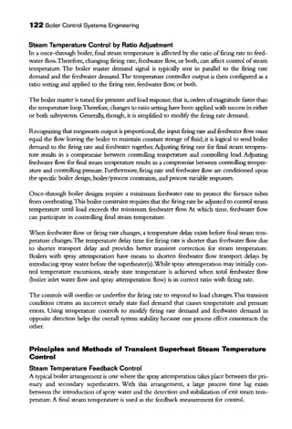
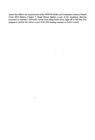
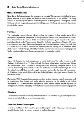
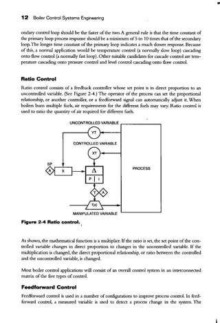
![88 Boiler Control Systems Engineering
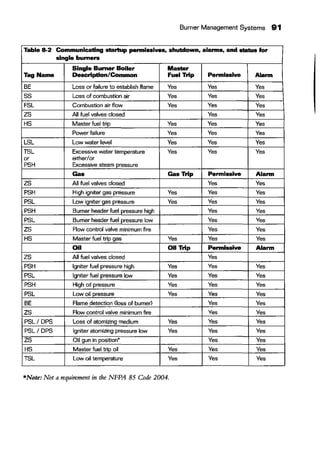
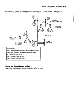
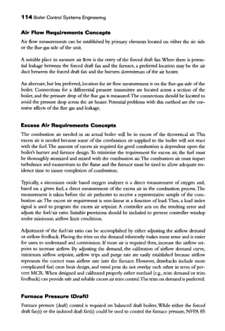
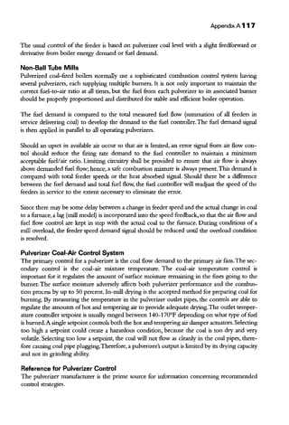
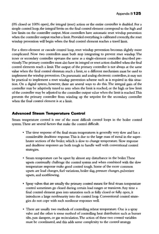
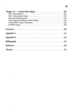
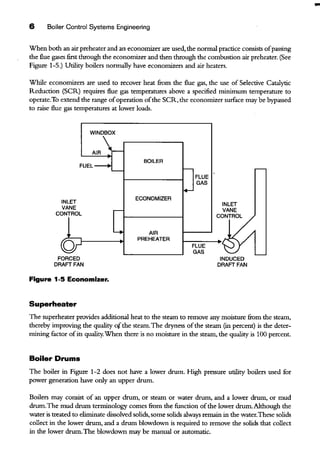
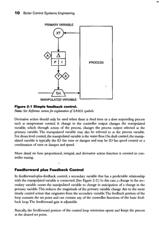
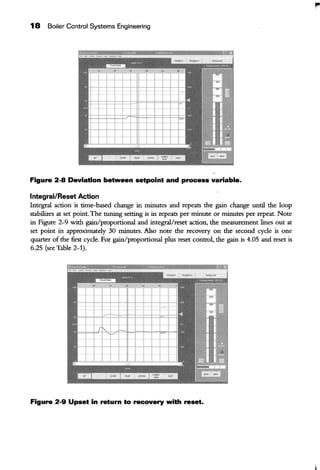
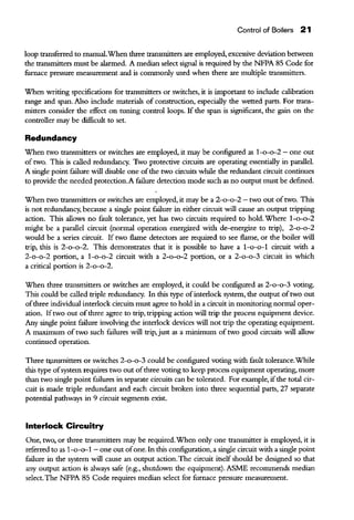
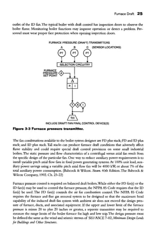
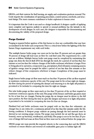
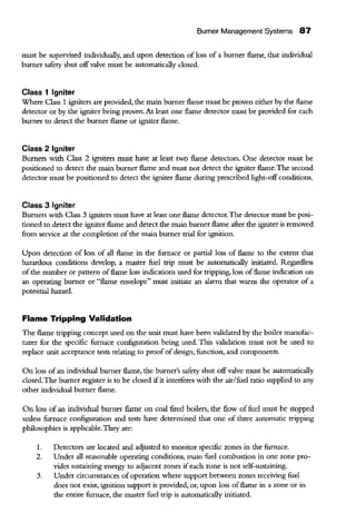
Figure 8-2 is a multiple burner boiler iuterlock system diagram.
~~~~~~~~~~~~~=~J~=R~l::::::=jCioseindivk:lualigniter I
safety shutoff valve(s)
Typical cause of trip indication 1and de-energize sparks
Igniter I______"T___,~~~~~~~~~~fuel ~ Igniter fuel trip tor Class 1 Igas _ 1Igniters, block 11
-T- ~
~~~~~~~~~~~~~~~~i=i~~ Close Igniter header
Igniter '---~ and Individual igniter
fuel __..., safety shutoff valve(s)
trip -----+---' and de-energizer sparks
logic
~
Q
G)JLossofiDfan(s)
8JLossofFDfan(s)
0 ]combustion airflow tow
0 ]High furnace pressure
0 ]Loss of all flame
0 [Partial loss of flame, introducing hazard
0 ]All fuel inputs shut off
e ]Manual trip switch
@ [tgniter fuel trip (Class 1 igniters)
S Jtgniterfuel trip (Class 1 igniters)
Q
Q
Q
Q
Master
'"''trip ~L......
logiC I r-""""
-
Master
'""'trip
relay(s)
Q JII-+Q '--
'-;:~
rr;·It~
Q~fuel Close main gas safety
trip f-.L-:--7-:-------+-...j shutoff valve(s) and
r+- logic ~ individual burner
_Q1 ...._____ safety shutoff valves
@ 1'~~~~~·~o~o~ll~b~om~o~cp~c~~~"~"'~~~;~~~=9~~~"~011J===- Closemainoilsafety
fuol f--..L-7-:--------:--...j shutoff valve(s) and
Q 1, trip ~ .__________._ individual bumer~
1
Atomizing medium pressure Improper --------..--
'___s"2.l:fclog~<~--- safety shutoff valves
Q IAll coal-firing equipment stopped or tripped ~ Y · Coal - I Stop coal flow I~ !or common coal-firing equipment tripped '----'--'--------~---lo-1 'to pulverizers
fuel r and burners
a I!loss of individual gas or oil burner I~ flame with one or more additional
stable burner flames present
@ ILoss of main coal burner flame
Q
trip
logic
Close individual burner safety shutoff valve(s)
and Individual igniter safety shutoff valve{s)
and de-energize associated sparks
Follow tripping strategy in 6,8,4
Figure 8-2 Interlock system for multiple burner boiler.
I
I](https://image.slidesharecdn.com/boilercontrolsystemengineering-190127214007/85/Boiler-control-system-engineering-107-320.jpg)