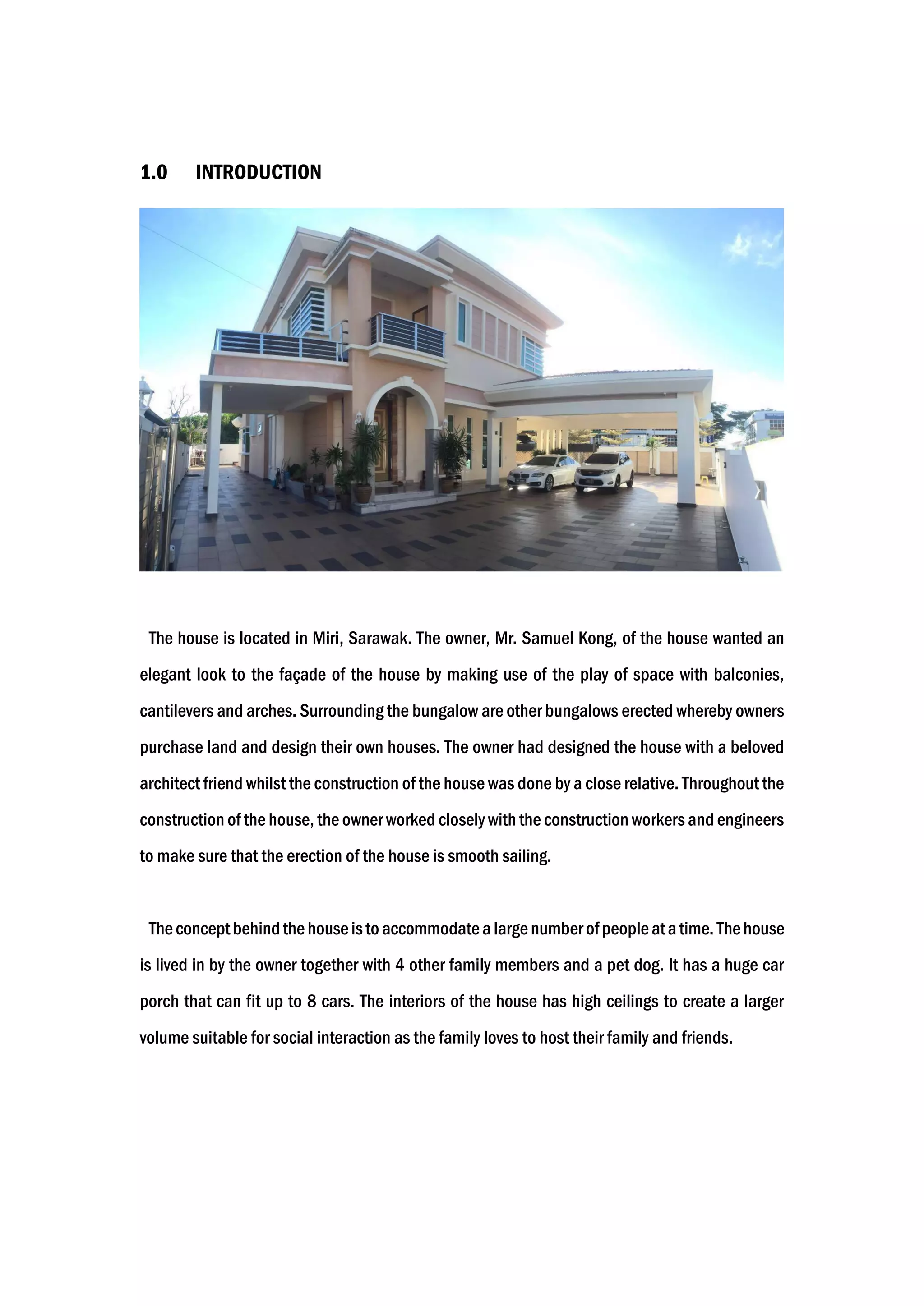
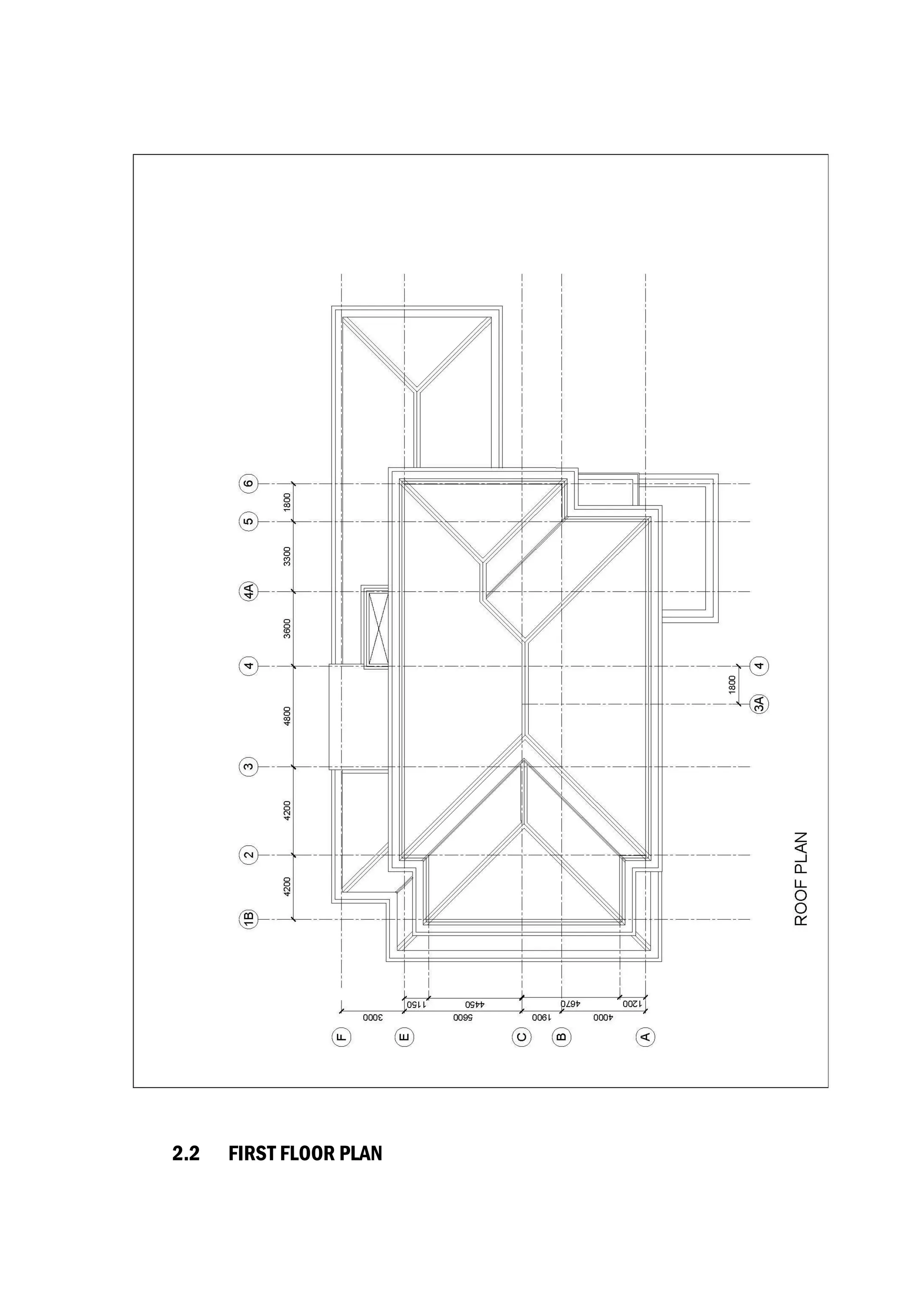
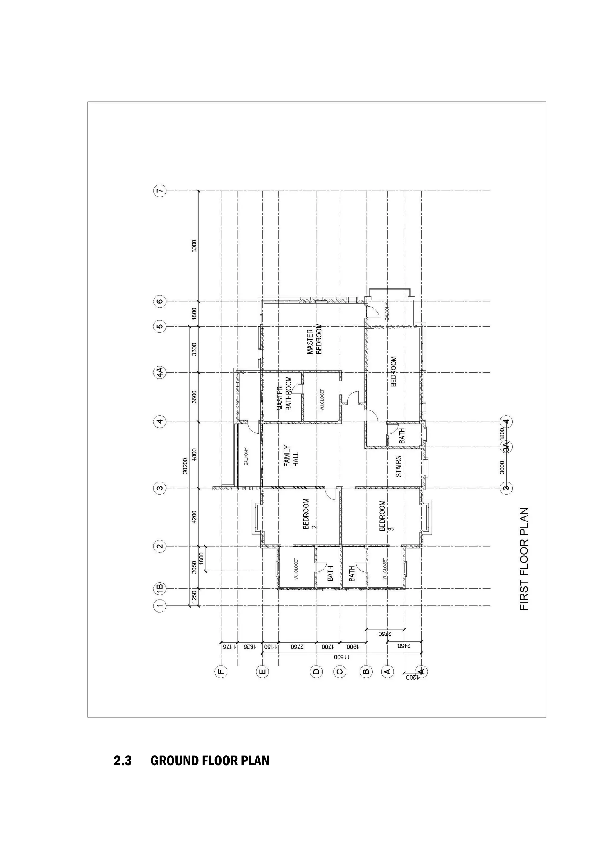
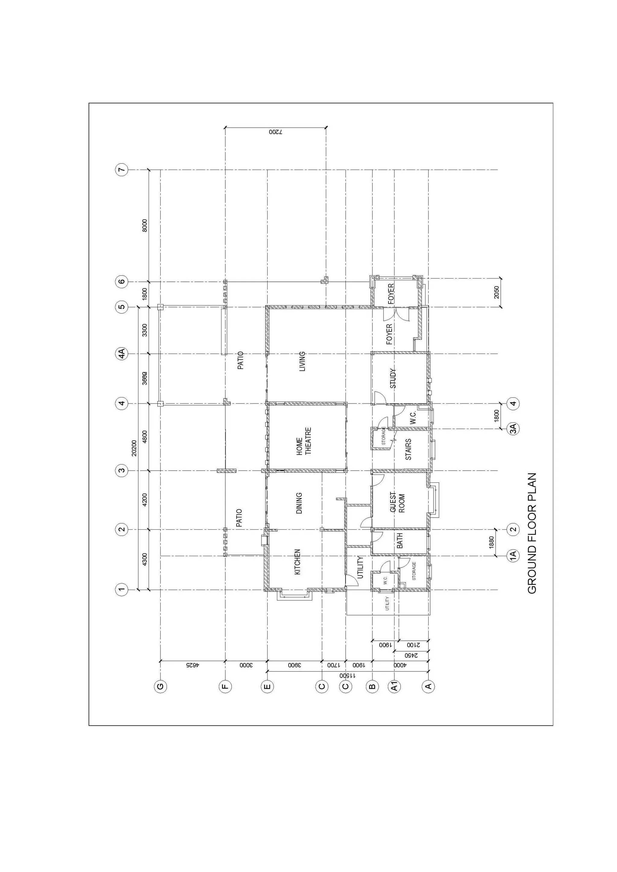
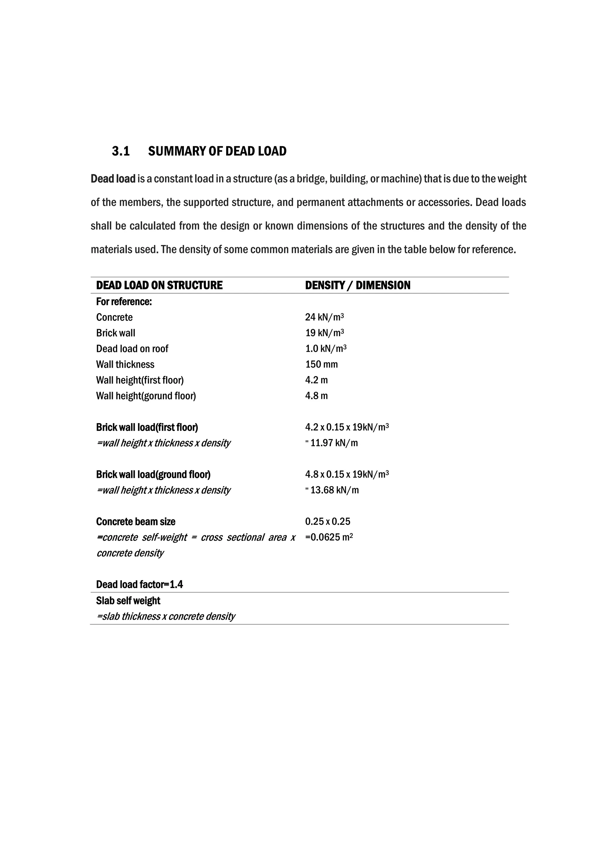
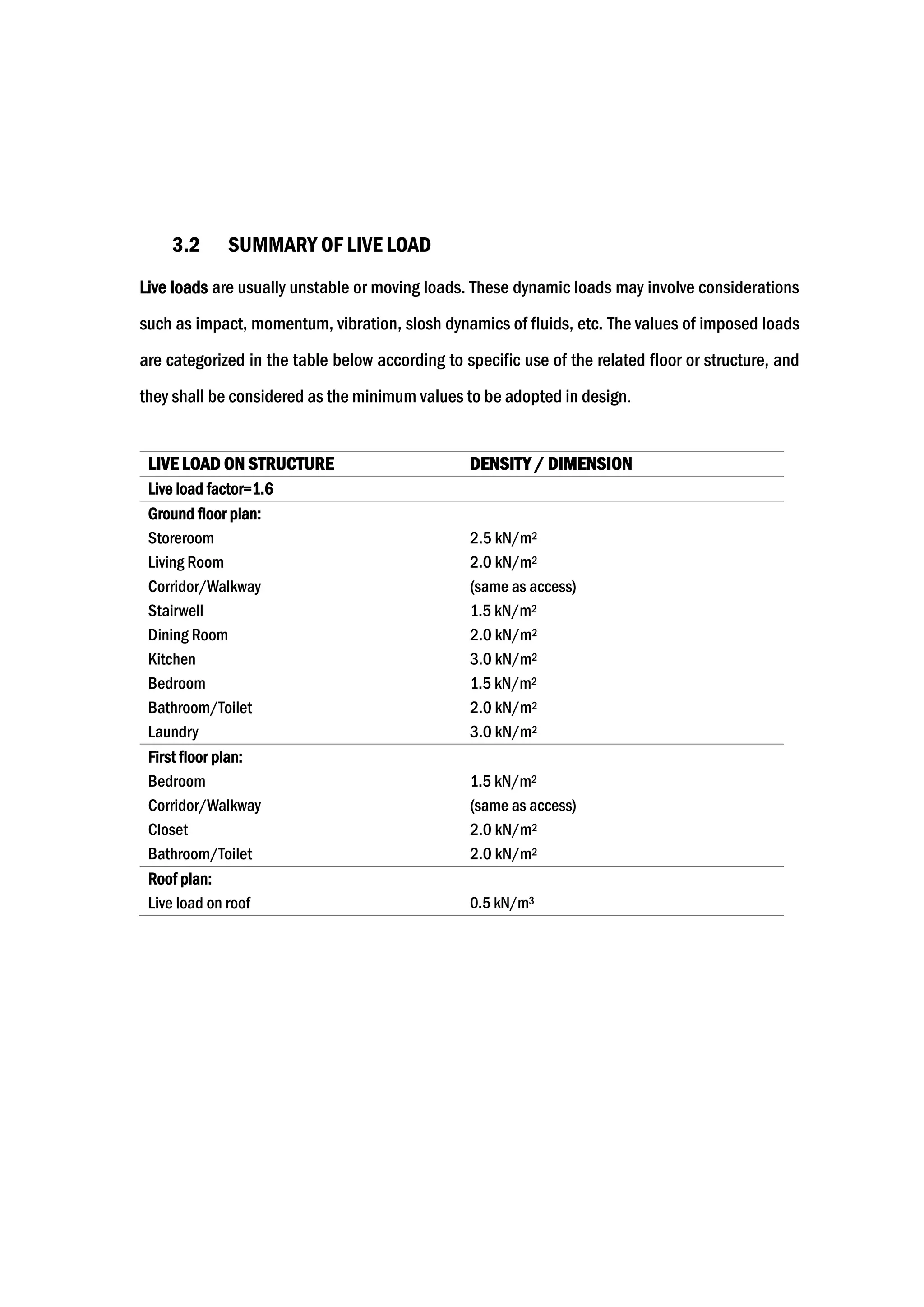
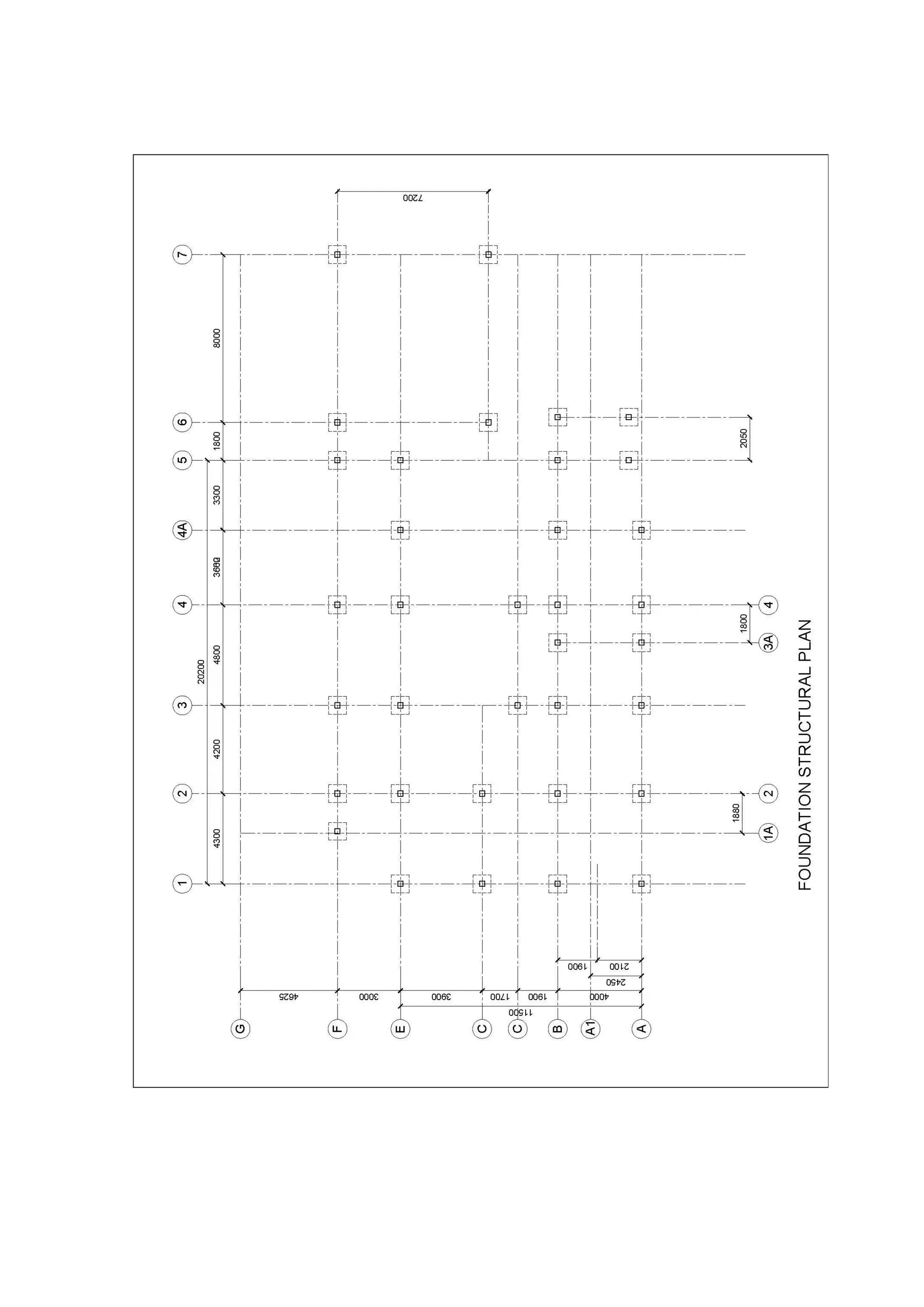
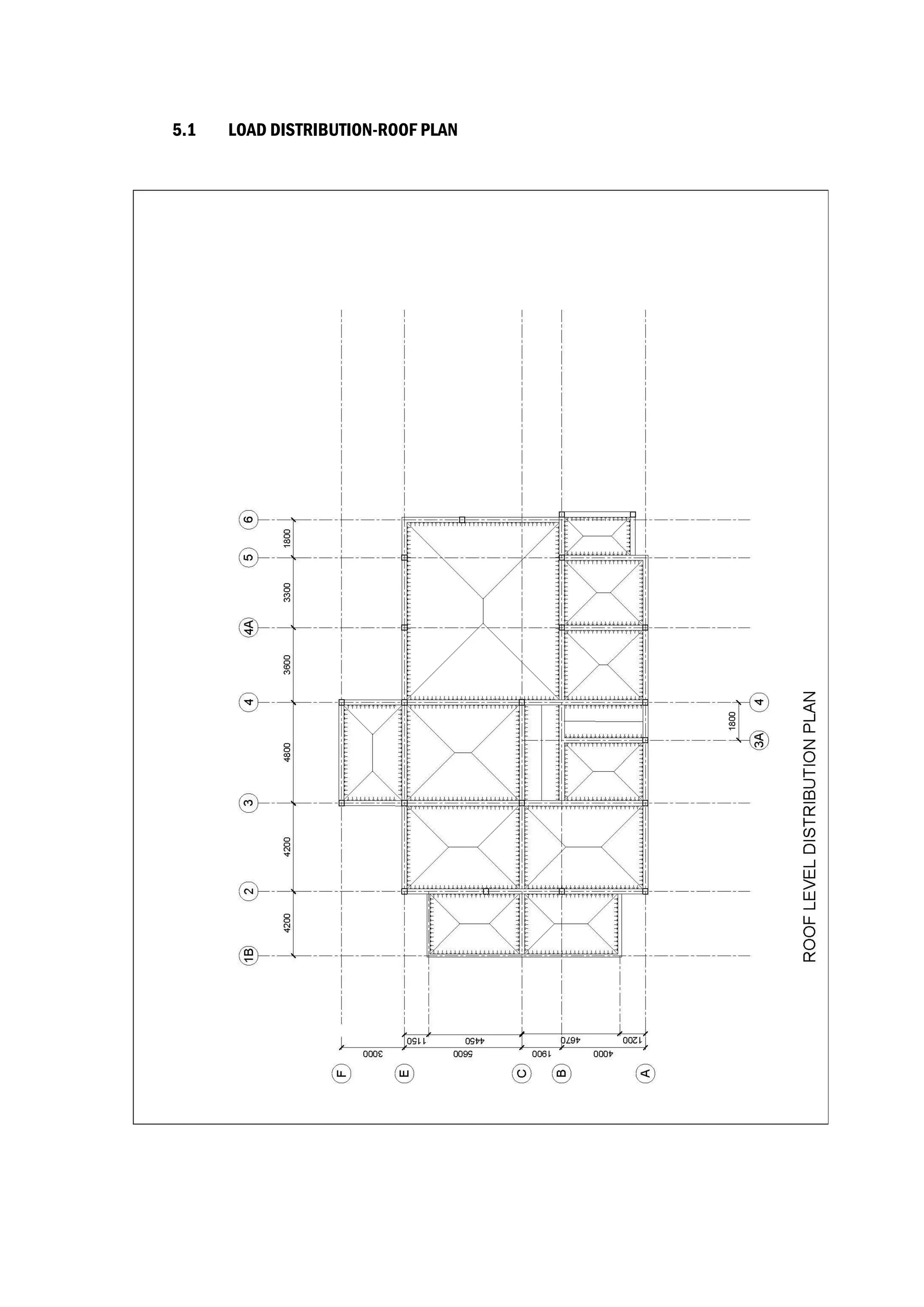
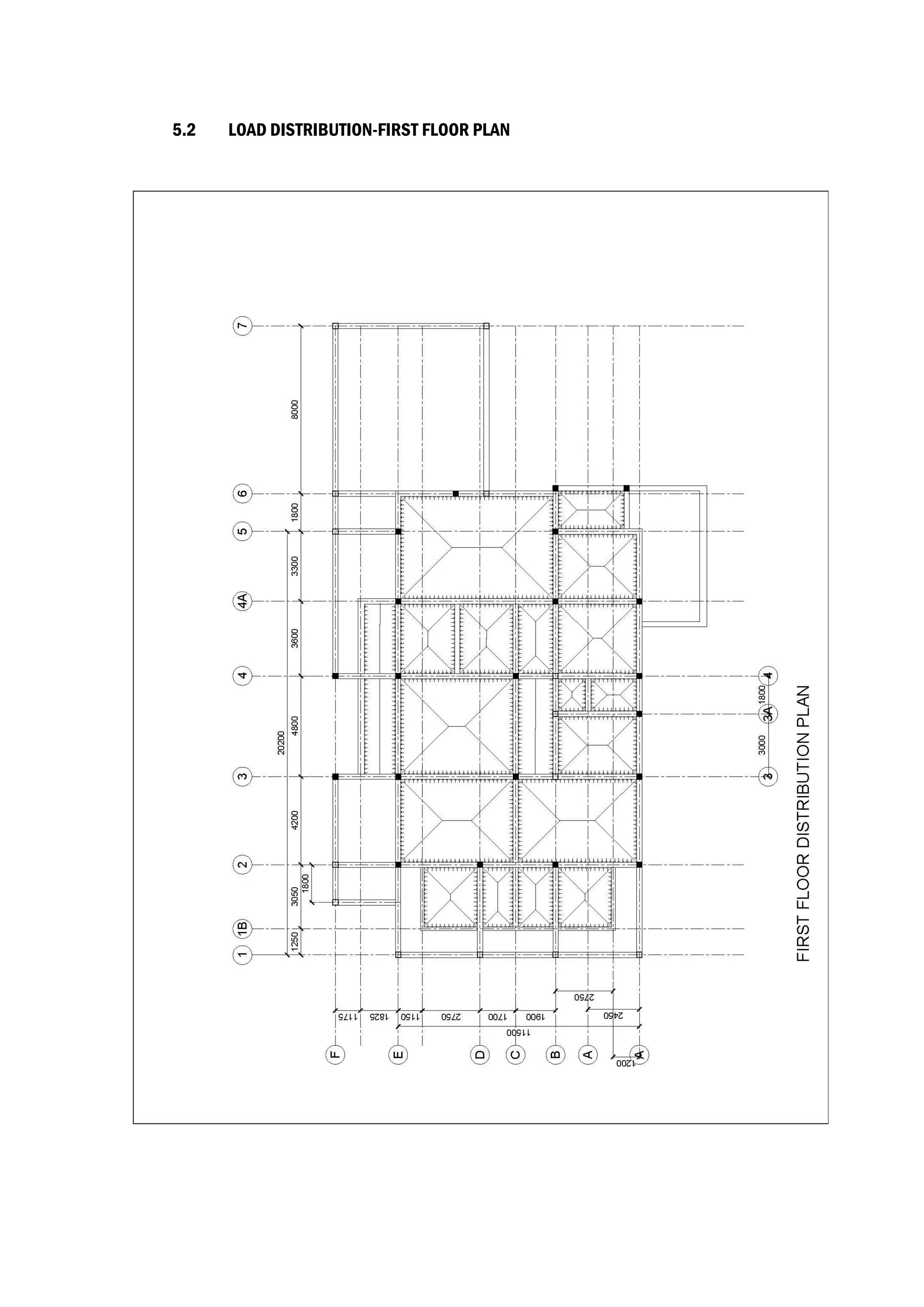
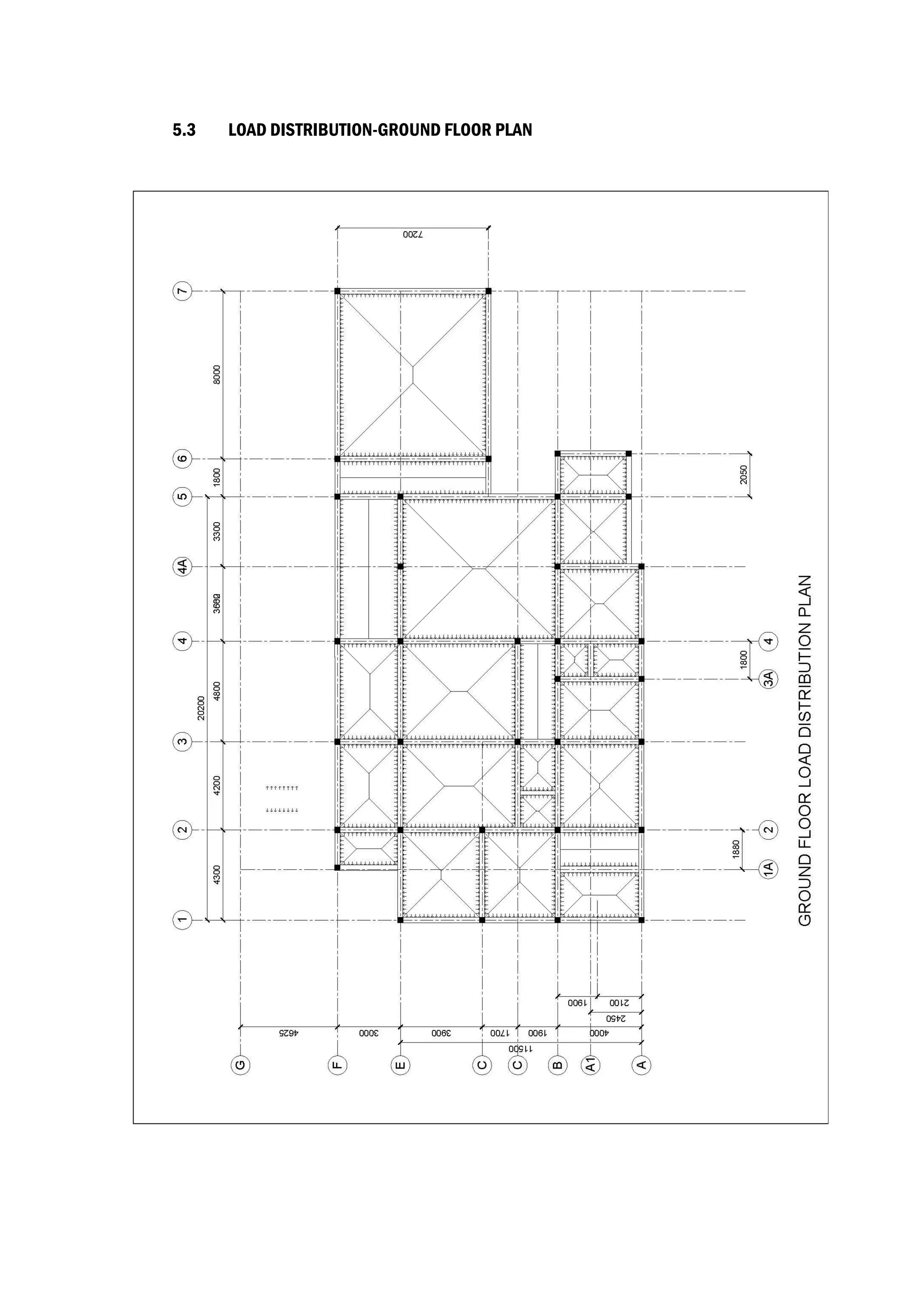
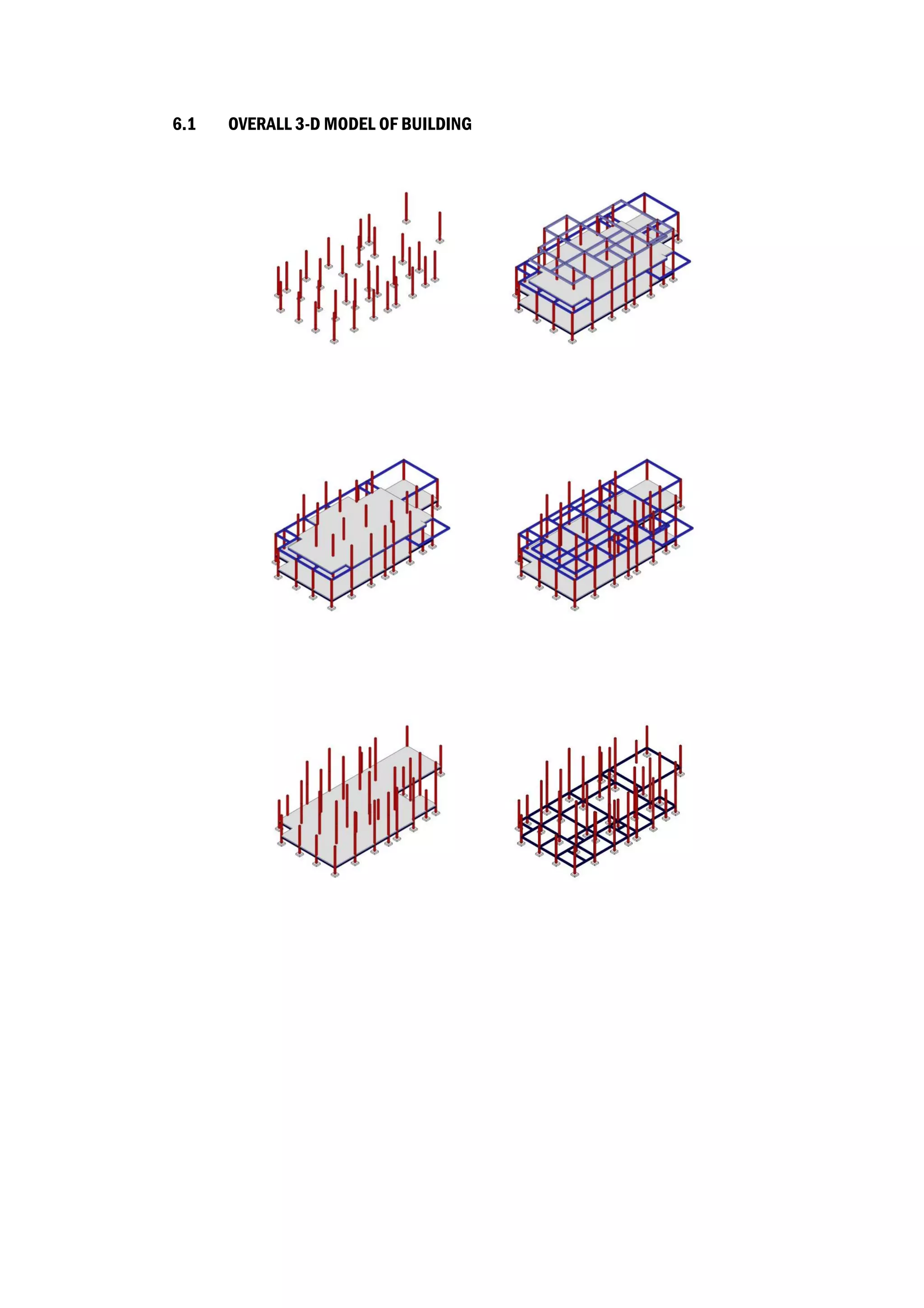
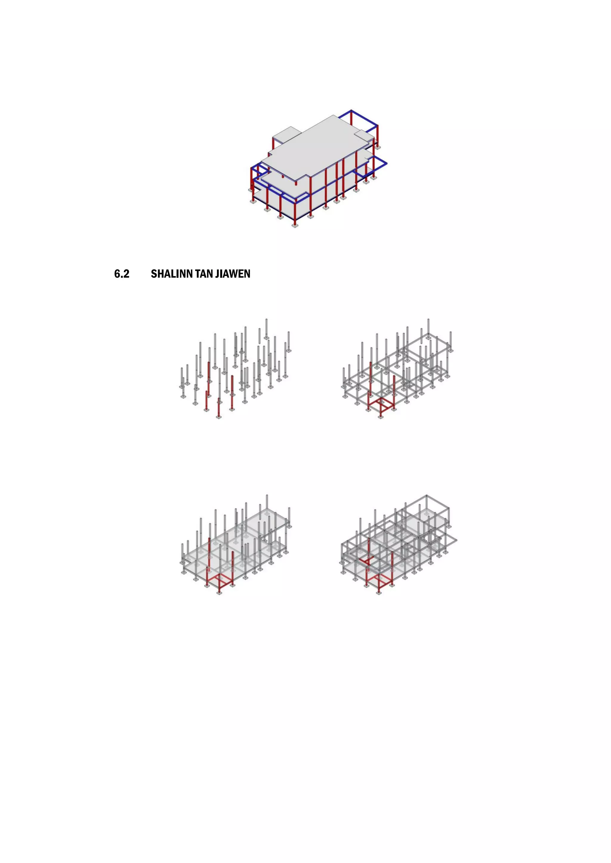
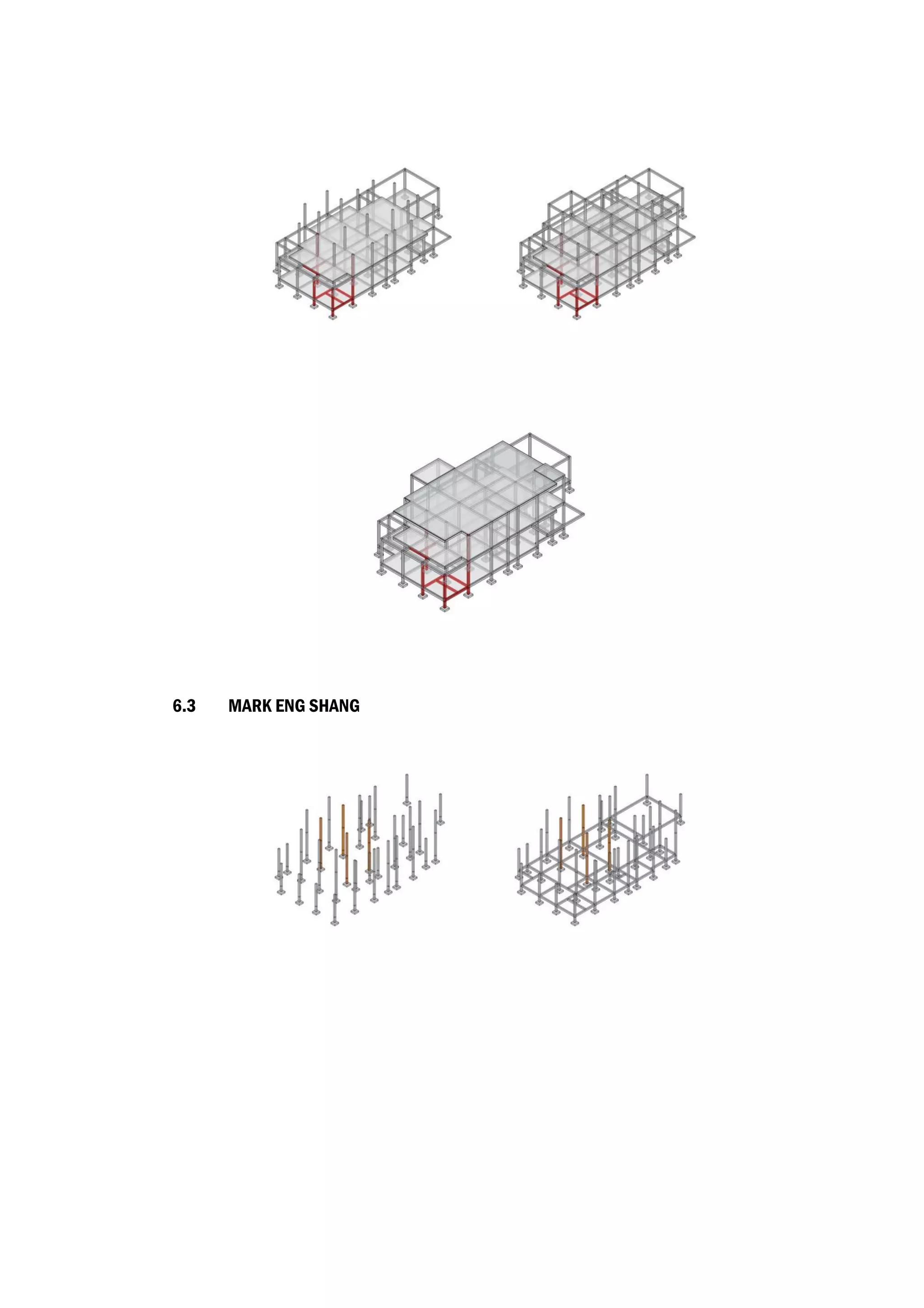
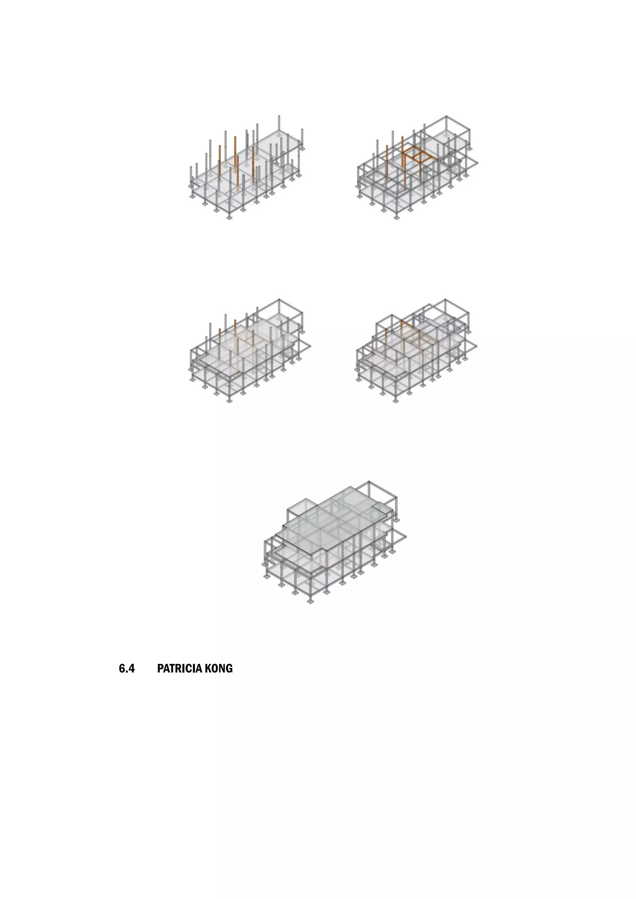
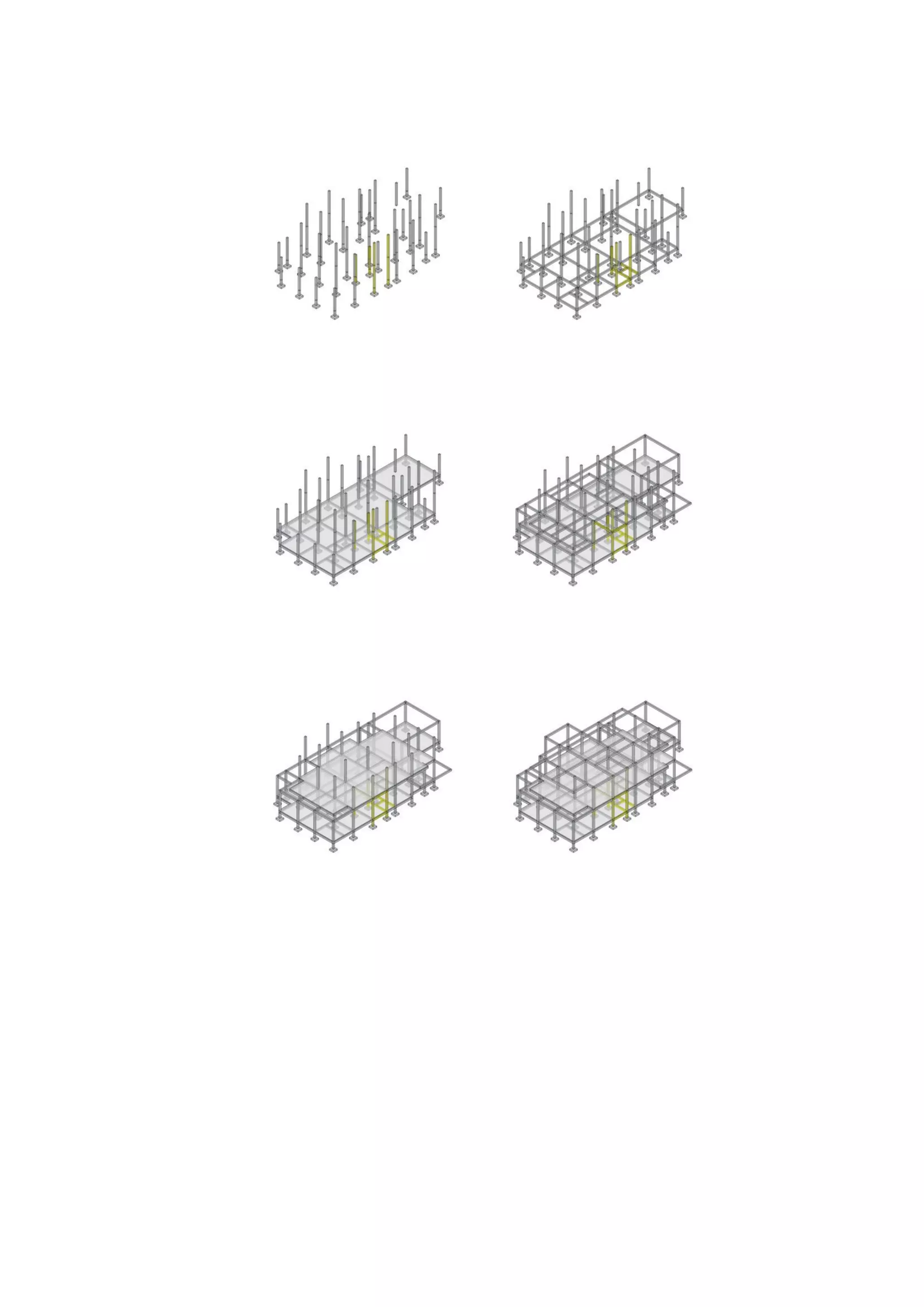
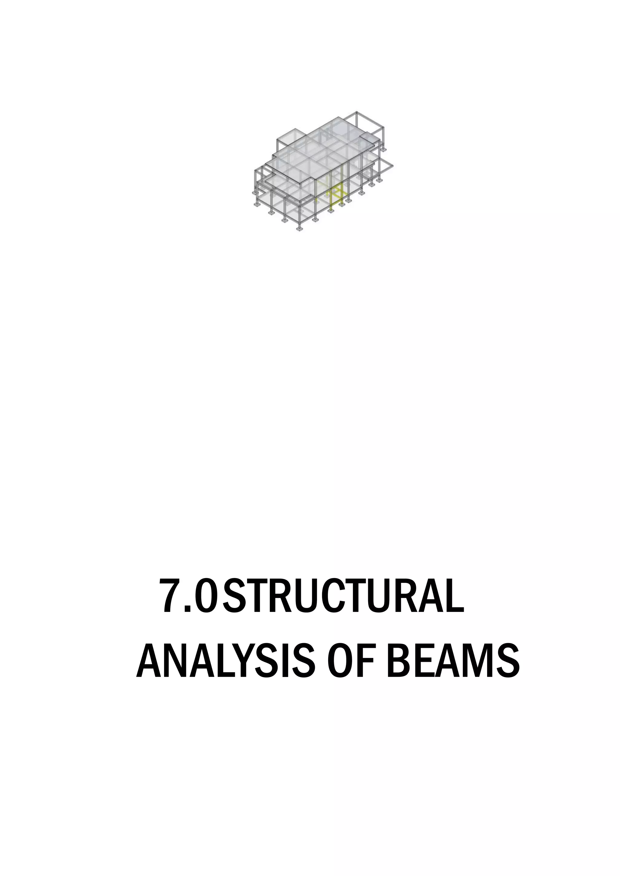
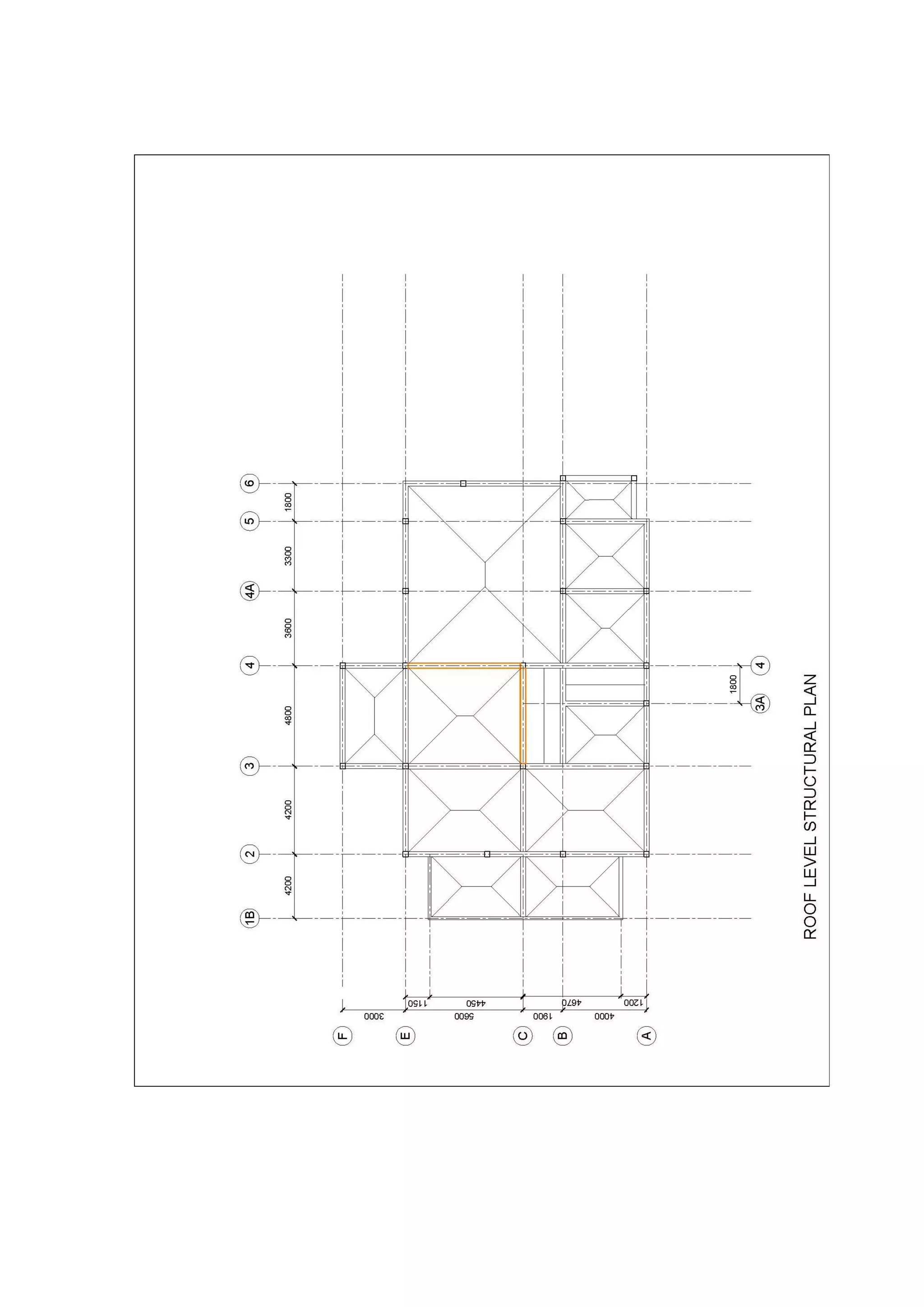
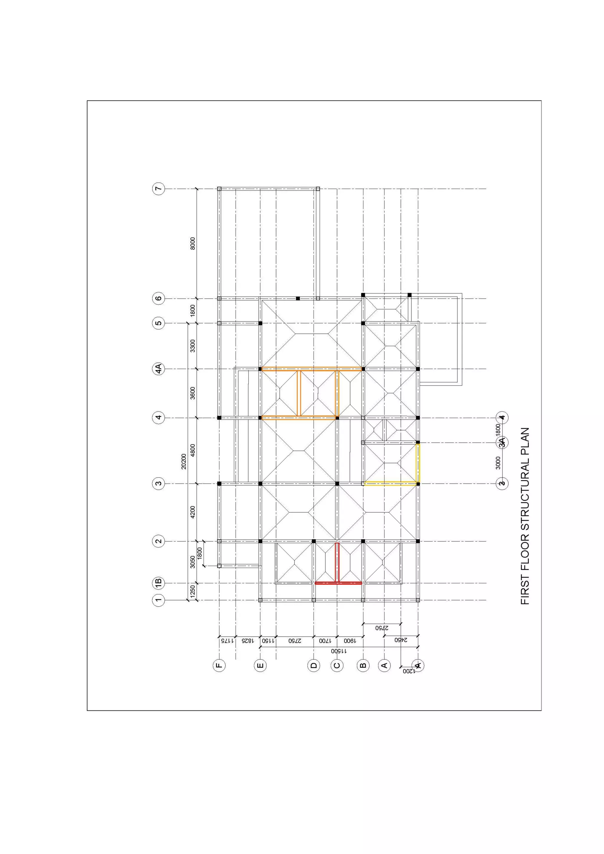
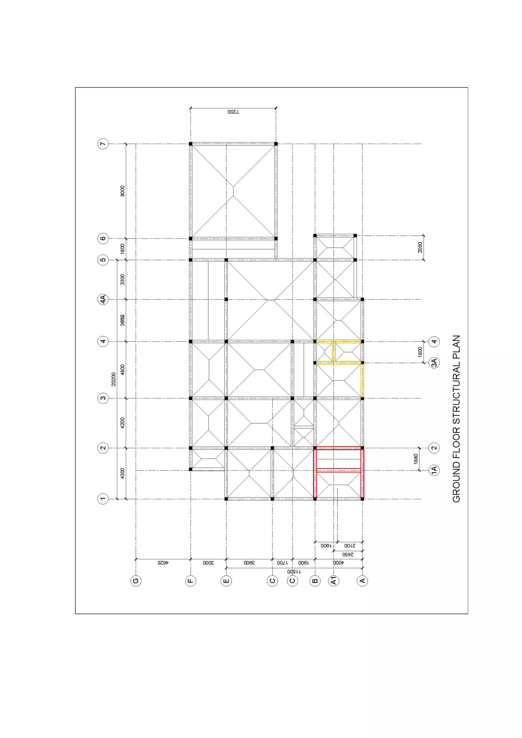
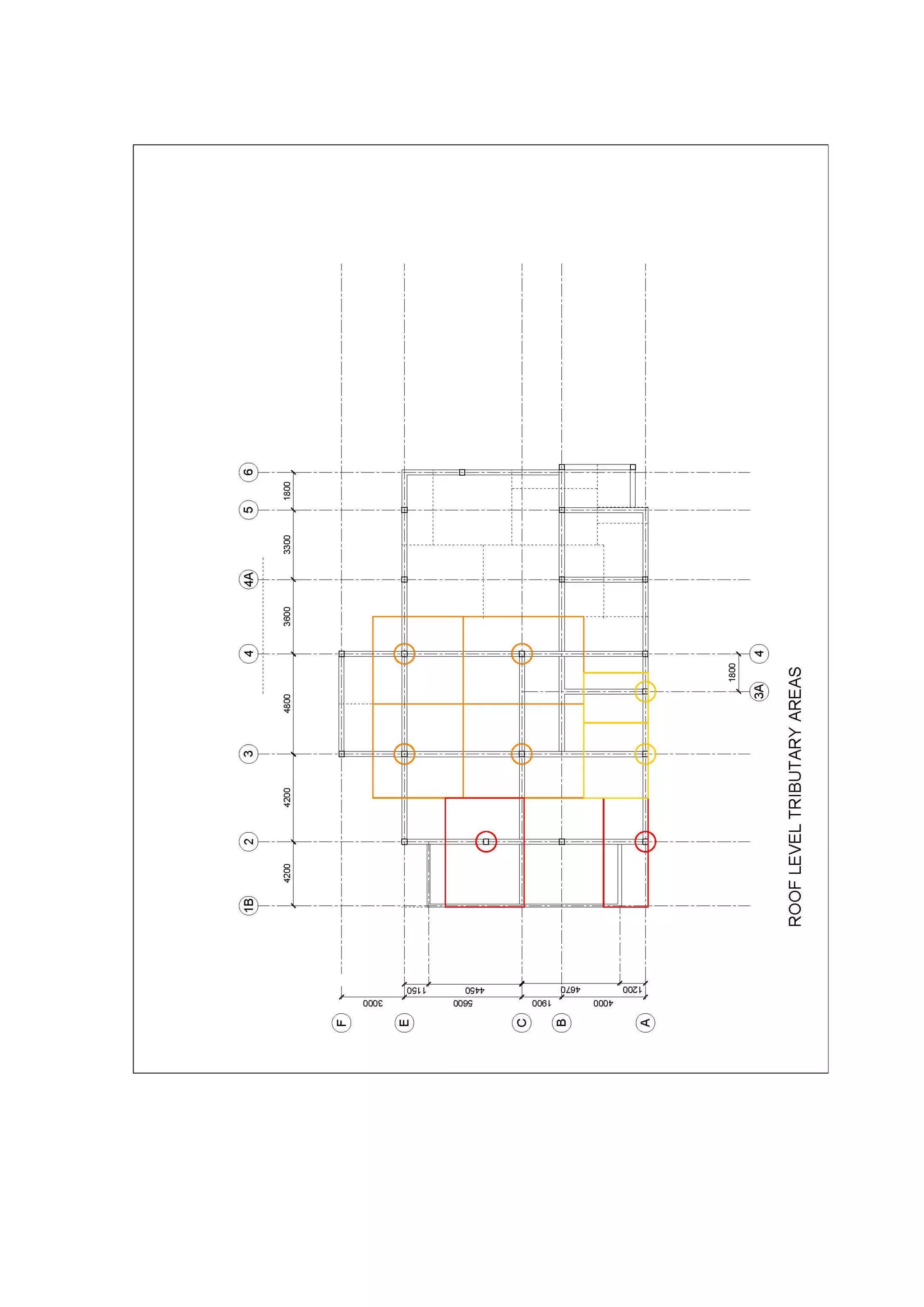
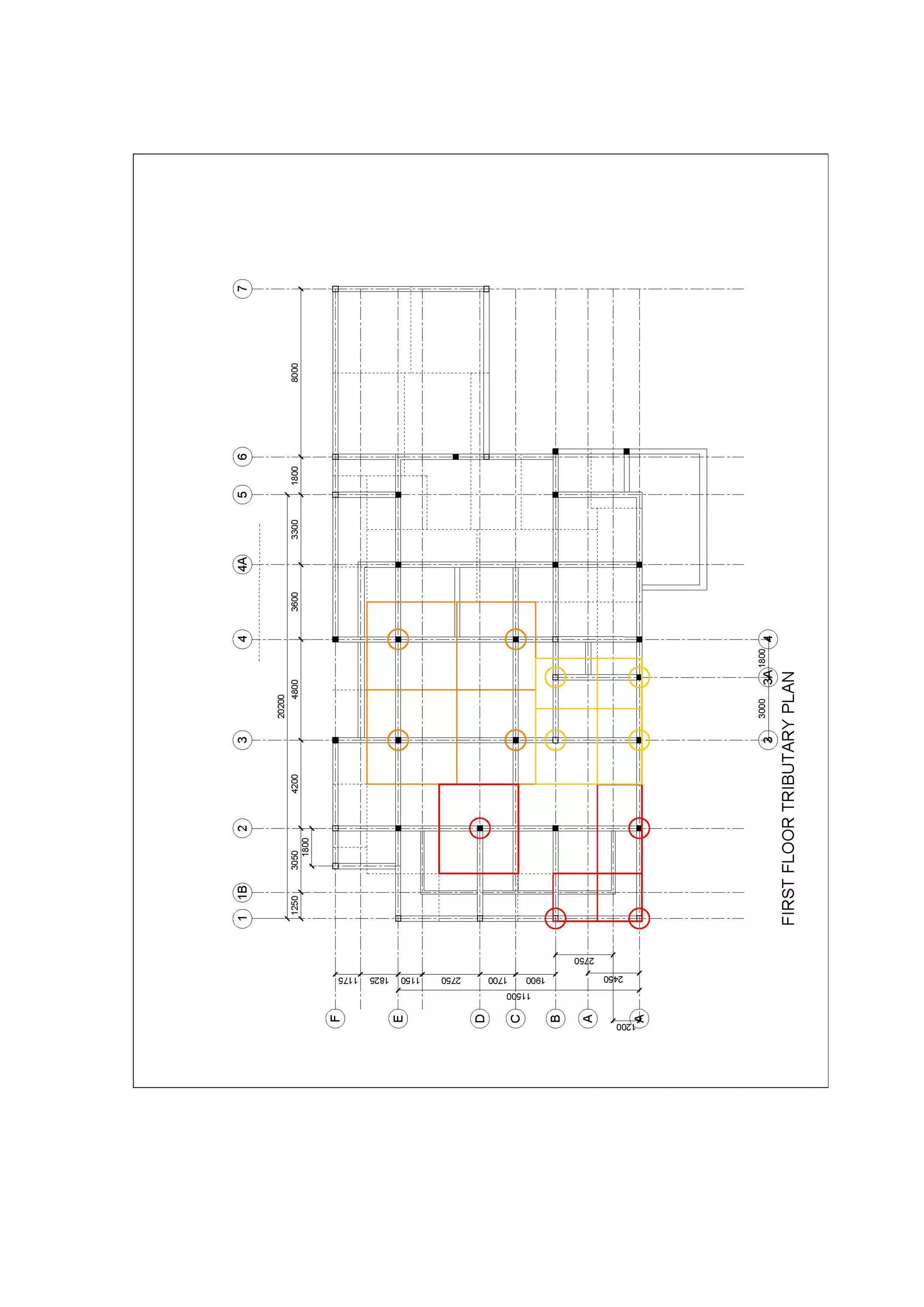
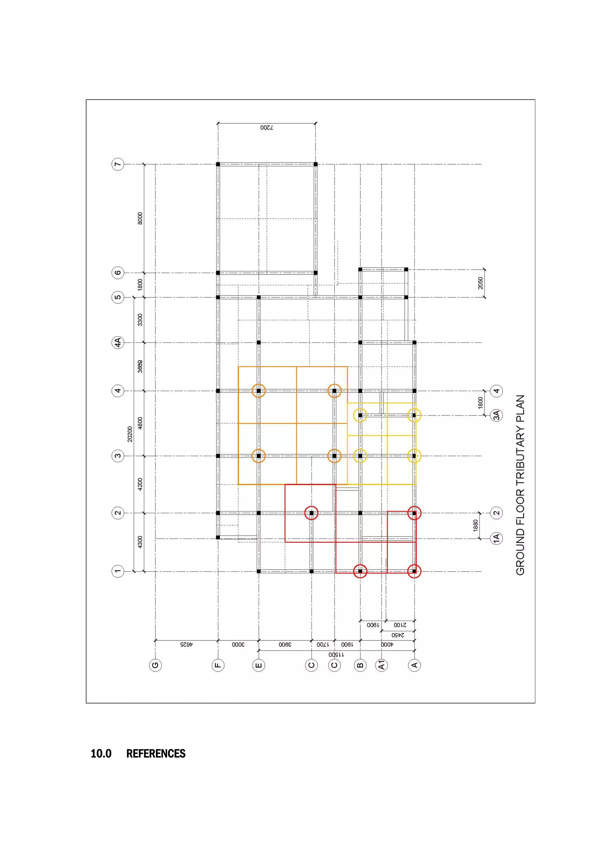
Building Structures (ARC2522/2523)
Project 2
ANALYSIS OF A REINFORCED CONCRETE
BUILDING
NAME(s)
Shalinn Tan Jiawen 0318714
Mark Eng Shang 0314187
Patricia Kong 0315837
LECTURER
Mr. Mohd Adib Ramli
CONTENTS
1.0 INTRODUCTION
2.0 ARCHITECTURAL DRAWINGS
2.1 ROOF PLAN
2.2 FIRST FLOOR PLAN
2.3 GROUND FLOOR PLAN
3.0 BRIEF INTRODUCTION
3.1 SUMMARY OF DEAD LOAD
3.2 SUMMARY OF LIVE LOAD
4.0 STRUCTURAL PLANS
4.1 STRUCTURAL ROOF PLAN
4.2 STRUCTURAL FIRST FLOOR PLAN
4.3 STRUCTURAL GROUND FLOOR PLAN
4.4 STRUCTURAL FOUNDATION PLAN
5.0 LOAD DISTRIBUTION PLANS FOR BEAM DESIGN
5.1 LOAD DISTRIBUTION-ROOF PLAN
5.2 LOAD DISTRIBUTION-FIRST FLOOR PLAN
5.3 LOAD DISTRIBUTION-GROUND FLOOR PLAN
6.0 3-D MODEL OF BUILDING
6.1 OVERALL 3-D MODEL OF BUILDING
6.2 SHALINN TAN JIAWEN
6.3 MARK ENG SHANG
6.4 PATRICIA KONG
7.0 STRUCTURAL ANALYSIS OF BEAMS
8.0 TRIBUTARY AREA PLANS FOR COLUMNS
8.1 TRIBUTARY AREA-ROOF PLAN
8.2 TRIBUTARY AREA-FIRST FLOOR PLAN
8.3 TRIBUTARY AREA-GROUND FLOOR PLAN
9.0 STRUCTURAL ANALYSIS OF COLUMNS
10.0 REFERENCES
1.0 INTRODUCTION
The house is located in Miri, Sarawak. The owner, Mr. Samuel Kong, of the house wanted an
elegant look to the façade of the house by making use of the play of space with balconies,
cantilevers and arches. Surrounding the bungalow are other bungalows erected whereby owners
purchase land and design their own houses. The owner had designed the house with a beloved
architect friend whilst the construction of the house was done by a close relative. Throughout the
construction of the house, the owner worked closely with the construction workers and engineers
to make sure that the erection of the house is smooth sailing.
Theconceptbehind thehouseistoaccommodatealargenumberofpeopleatatime. Thehouse
is lived in by the owner together with 4 other family members and a pet dog. It has a huge car
porch that can fit up to 8 cars. The interiors of the house has high ceilings to create a larger
volume suitable for social interaction as the family loves to host their family and friends.
2.0 ARCHITECTURAL
DRAWINGS
2.1 ROOF PLAN
2.2 FIRST FLOOR PLAN
2.3 GROUND FLOOR PLAN
3.0BRIEF
INTRODUCTION
3.1 SUMMARY OF DEAD LOAD
Dead loadisaconstantloadinastructure(asabridge, building,ormachine)thatisduetotheweight
of the members, the supported structure, and permanent attachments or accessories. Dead loads
shall be calculated from the design or known dimensions of the structures and the density of the
materials used. The density of some common materials are given in the table below for reference.
DEAD LOAD ON STRUCTURE DENSITY / DIMENSION
For reference:
Concrete
Brick wall
Dead load on roof
Wall thickness
Wall height(first floor)
Wall height(gorund floor)
Brick wall load(first floor)
=wall height x thickness x density
Brick wall load(ground floor)
=wall height x thickness x density
Concrete beam size
=concrete self-weight = cross sectional area x
concrete density
Dead load factor=1.4
24 kN/m3
19 kN/m3
1.0 kN/m3
150 mm
4.2 m
4.8 m
4.2 x 0.15 x 19kN/m3
= 11.97 kN/m
4.8 x 0.15 x 19kN/m3
= 13.68 kN/m
0.25 x 0.25
=0.0625 m2
Slab self weight
=slab thickness x concrete density
3.2 SUMMARY OF LIVE LOAD
Live loads are usually unstable or moving loads. These dynamic loads may involve considerations
such as impact, momentum, vibration, slosh dynamics of fluids, etc. The values of imposed loads
are categorized in the table below according to specific use of the related floor or structure, and
they shall be considered as the minimum values to be adopted in design.
LIVE LOAD ON STRUCTURE DENSITY / DIMENSION
Live load factor=1.6
Ground floor plan:
Storeroom
Living Room
Corridor/Walkway
Stairwell
Dining Room
Kitchen
Bedroom
Bathroom/Toilet
Laundry
2.5 kN/m2
2.0 kN/m2
(same as access)
1.5 kN/m2
2.0 kN/m2
3.0 kN/m2
1.5 kN/m2
2.0 kN/m2
3.0 kN/m2
First floor plan:
Bedroom
Corridor/Walkway
Closet
Bathroom/Toilet
1.5 kN/m2
(same as access)
2.0 kN/m2
2.0 kN/m2
Roof plan:
Live load on roof 0.5 kN/m3
4.0STRUCTURAL
PLANS
4.1 STRUCTURAL ROOF PLAN
4.2 STRUCTURAL FIRST FLOOR PLAN
4.3 STRUCTURAL GROUND FLOOR PLAN
4.4 STRUCTURAL FOUNDATION PLAN
5.0LOAD
DISTRIBUTION PLAN
FOR BEAM DESIGN
5.1 LOAD DISTRIBUTION-ROOF PLAN
5.2 LOAD DISTRIBUTION-FIRST FLOOR PLAN
5.3 LOAD DISTRIBUTION-GROUND FLOOR PLAN
6.03-D MODEL OF
BUILDING
6.1 OVERALL 3-D MODEL OF BUILDING
6.2 SHALINN TAN JIAWEN
6.3 MARK ENG SHANG
6.4 PATRICIA KONG
7.0STRUCTURAL
ANALYSIS OF BEAMS
Red-Shalinn Tan ; Orange-Mark Eng ; Yellow-Patricia Kong
8.0TRIBUTARY AREA
PLANS FOR
COLUMNS
8.1 TRIBUTARY AREA-ROOF PLAN
8.2 TRIBUTARY AREA-FIRST FLOOR PLAN
8.3 TRIBUTARY AREA-GROUND FLOOR PLAN
9.0STRUCTURAL
ANALYSIS OF
COLUMNS
Red-Shalinn Tan ; Orange-Mark Eng ; Yellow-Patricia Kong
10.0 REFERENCES
1. BS6399Part1WoodFloorLoadings. (2009) (1st ed., pp. 5-14). Retrieved from
http://file:///C:/Users/User/Downloads/BS6399Part1WoodFloorLoadings.pdf
2. Code of Practice for Dead and Imposed Loads 2011. (2011) (1st ed., pp. 8-20). Hong
Kong. Retrieved from http://www.bd.gov.hk/english/documents/code/DIL2011e.pdf
3. Johari, N. (2016). SLABS2016. Lecture, LT3.
4. Mohd, A. (2016). Beams Part 1. Lecture, LT3.
5. Mohd, A. (2016). Beams Part 2. Lecture, LT3.
6. Mohd, A. (2016). Columns. Lecture, LT3.
7. Uniform Building By-laws 1984. (1996). Kuala Lumpur.

BUILDING STRUCTURE REPORT

  • 1.
    Building Structures (ARC2522/2523) Project2 ANALYSIS OF A REINFORCED CONCRETE BUILDING NAME(s) Shalinn Tan Jiawen 0318714 Mark Eng Shang 0314187 Patricia Kong 0315837 LECTURER Mr. Mohd Adib Ramli
  • 2.
    CONTENTS 1.0 INTRODUCTION 2.0 ARCHITECTURALDRAWINGS 2.1 ROOF PLAN 2.2 FIRST FLOOR PLAN 2.3 GROUND FLOOR PLAN 3.0 BRIEF INTRODUCTION 3.1 SUMMARY OF DEAD LOAD 3.2 SUMMARY OF LIVE LOAD 4.0 STRUCTURAL PLANS 4.1 STRUCTURAL ROOF PLAN 4.2 STRUCTURAL FIRST FLOOR PLAN 4.3 STRUCTURAL GROUND FLOOR PLAN 4.4 STRUCTURAL FOUNDATION PLAN 5.0 LOAD DISTRIBUTION PLANS FOR BEAM DESIGN 5.1 LOAD DISTRIBUTION-ROOF PLAN 5.2 LOAD DISTRIBUTION-FIRST FLOOR PLAN 5.3 LOAD DISTRIBUTION-GROUND FLOOR PLAN 6.0 3-D MODEL OF BUILDING 6.1 OVERALL 3-D MODEL OF BUILDING 6.2 SHALINN TAN JIAWEN 6.3 MARK ENG SHANG 6.4 PATRICIA KONG 7.0 STRUCTURAL ANALYSIS OF BEAMS 8.0 TRIBUTARY AREA PLANS FOR COLUMNS 8.1 TRIBUTARY AREA-ROOF PLAN 8.2 TRIBUTARY AREA-FIRST FLOOR PLAN 8.3 TRIBUTARY AREA-GROUND FLOOR PLAN 9.0 STRUCTURAL ANALYSIS OF COLUMNS 10.0 REFERENCES
  • 3.
    1.0 INTRODUCTION The houseis located in Miri, Sarawak. The owner, Mr. Samuel Kong, of the house wanted an elegant look to the façade of the house by making use of the play of space with balconies, cantilevers and arches. Surrounding the bungalow are other bungalows erected whereby owners purchase land and design their own houses. The owner had designed the house with a beloved architect friend whilst the construction of the house was done by a close relative. Throughout the construction of the house, the owner worked closely with the construction workers and engineers to make sure that the erection of the house is smooth sailing. Theconceptbehind thehouseistoaccommodatealargenumberofpeopleatatime. Thehouse is lived in by the owner together with 4 other family members and a pet dog. It has a huge car porch that can fit up to 8 cars. The interiors of the house has high ceilings to create a larger volume suitable for social interaction as the family loves to host their family and friends.
  • 4.
  • 5.
  • 6.
  • 7.
  • 9.
  • 10.
    3.1 SUMMARY OFDEAD LOAD Dead loadisaconstantloadinastructure(asabridge, building,ormachine)thatisduetotheweight of the members, the supported structure, and permanent attachments or accessories. Dead loads shall be calculated from the design or known dimensions of the structures and the density of the materials used. The density of some common materials are given in the table below for reference. DEAD LOAD ON STRUCTURE DENSITY / DIMENSION For reference: Concrete Brick wall Dead load on roof Wall thickness Wall height(first floor) Wall height(gorund floor) Brick wall load(first floor) =wall height x thickness x density Brick wall load(ground floor) =wall height x thickness x density Concrete beam size =concrete self-weight = cross sectional area x concrete density Dead load factor=1.4 24 kN/m3 19 kN/m3 1.0 kN/m3 150 mm 4.2 m 4.8 m 4.2 x 0.15 x 19kN/m3 = 11.97 kN/m 4.8 x 0.15 x 19kN/m3 = 13.68 kN/m 0.25 x 0.25 =0.0625 m2 Slab self weight =slab thickness x concrete density
  • 11.
    3.2 SUMMARY OFLIVE LOAD Live loads are usually unstable or moving loads. These dynamic loads may involve considerations such as impact, momentum, vibration, slosh dynamics of fluids, etc. The values of imposed loads are categorized in the table below according to specific use of the related floor or structure, and they shall be considered as the minimum values to be adopted in design. LIVE LOAD ON STRUCTURE DENSITY / DIMENSION Live load factor=1.6 Ground floor plan: Storeroom Living Room Corridor/Walkway Stairwell Dining Room Kitchen Bedroom Bathroom/Toilet Laundry 2.5 kN/m2 2.0 kN/m2 (same as access) 1.5 kN/m2 2.0 kN/m2 3.0 kN/m2 1.5 kN/m2 2.0 kN/m2 3.0 kN/m2 First floor plan: Bedroom Corridor/Walkway Closet Bathroom/Toilet 1.5 kN/m2 (same as access) 2.0 kN/m2 2.0 kN/m2 Roof plan: Live load on roof 0.5 kN/m3
  • 12.
  • 13.
  • 14.
  • 15.
  • 16.
  • 18.
  • 19.
  • 20.
  • 21.
  • 22.
  • 23.
    6.1 OVERALL 3-DMODEL OF BUILDING
  • 24.
  • 25.
  • 26.
  • 28.
  • 29.
    Red-Shalinn Tan ;Orange-Mark Eng ; Yellow-Patricia Kong
  • 33.
  • 34.
  • 35.
  • 36.
  • 38.
  • 39.
    Red-Shalinn Tan ;Orange-Mark Eng ; Yellow-Patricia Kong
  • 42.
  • 43.
    1. BS6399Part1WoodFloorLoadings. (2009)(1st ed., pp. 5-14). Retrieved from http://file:///C:/Users/User/Downloads/BS6399Part1WoodFloorLoadings.pdf 2. Code of Practice for Dead and Imposed Loads 2011. (2011) (1st ed., pp. 8-20). Hong Kong. Retrieved from http://www.bd.gov.hk/english/documents/code/DIL2011e.pdf 3. Johari, N. (2016). SLABS2016. Lecture, LT3. 4. Mohd, A. (2016). Beams Part 1. Lecture, LT3. 5. Mohd, A. (2016). Beams Part 2. Lecture, LT3. 6. Mohd, A. (2016). Columns. Lecture, LT3. 7. Uniform Building By-laws 1984. (1996). Kuala Lumpur.