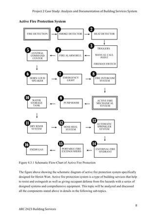
SCHOOL OF ARCHITECTURE, BUILDING & DESIGN
ARC 2423 BUILDING SERVICES
PROJECT 2 CASE STUDY
ANALYSIS AND DOCUMENTATION OF
BUILDING
SERVICES SYSTEM
GROUP MEMBER STUDENT ID
CHUNG WEI JIN 0313789
EE XIN HUA 0314089
LIEW QIAO LI 015671
LIM YEE QUN 0319121
LING HUI SIM 0313855
TAN JOU WEN 0313752
Project 2 Case Study: Analysis and Documentation of Building Services System
1
ARC 2423 Building Services
INDEX CONTENT
1. ABSTRACT
2. ACKNOWLEDGEMENT
3. INTRODUCTION- HERIOT WATT UNIVERSITY
4. FIRE PROTECTION SYSTEM
4.1 Introduction
4.2 Literature Review
4.3 Active Fire Protection System
4.3.2 Fire Detection System & Alarm System
4.3.2.1 Smoke Detector
4.3.2.2 Heat Detector
4.3.2.3 Manual Call Point
4.3.2.4 Fireman Switch
4.3.2.5 Fire Alarm Panel
4.3.2.6 Central command Center
4.3.2.7 Horn Loud Speaker
4.3.2.8 Emergency Light
4.3.3 Fire Intercom System
4.3.4 Water Based System
4.3.4.1 Pumps
4.3.4.2 Water Storage Tank
4.3.4.3 Dry Riser System
4.3.4.4 Hose Real System
4.3.4.5 Automatic Sprinkler System
4.3.4.6 External Fire Hydrant
4.3.5 Non-Water Based System
4.3.5.1 Portable Fire Extinguishers
4.3.5.2 FM200 Gas
4.4 Passive fire protection system
4.4.1 Separation of fire risk area
4.4.2 Fire rated door
4.4.3 Emergency exit signage
4.4.4 Smoke curtain
4.4.5 Fire emergency staircase
4.5 Conclusion
Project 2 Case Study: Analysis and Documentation of Building Services System
2
ARC 2423 Building Services
5 MECHANICAL VENTILATION SYSTEM
5.1 Introduction
5.2 Literature Review
5.3 Supply & Exhaust System
5.3.1 Cabinet Fan/ Double Inlet Centrifugal Fan with Backward Wheels
5.3.2 Supply Air Grille
5.3.3 Return Air Grille
5.4 Smoke Clearance Ventilation System
5.4.1 Censor and Switch
5.4.2 Damper
5.5 Conclusion
6 AIR CONDITIONING SYSTEM
6.1 Introduction
6.2 Literature Review
6.2.1 District Cooling system
6.2.2 Split Unit system
6.3 Case Study
6.3.1 Introduction to Air Conditioning System in Heriot Watt University
6.3.2 Gas District Cooling
6.3.2.1 Heat Exchanger
6.3.2.2 Air Handling Unit
6.3.2.3 Chill Water Cassette Fan Coil Unit (FCU)
6.3.3 Split Unit System
6.3.3.1 Split Unit without Outside Air
6.3.3.1.1 Outdoor Unit
6.3.3.1.2 Indoor Unit
6.3.3.2 Variable Refrigerant Volume (VRV)
6.3.3.2.1 Outdoor Unit
6.4 Conclusion
Project 2 Case Study: Analysis and Documentation of Building Services System
3
ARC 2423 Building Services
7 MECHANICAL TRANSPORTATION SYSTEM
7.1 Introduction
7.2 Literature Review
7.3 Types of Elevator
7.4 Case Study
7.4.1 Drawings
7.4.2 Elevator Components
7.4.2.1 Traction Machine
7.4.2.2 Control Panel
7.4.2.3 Buffer
7.4.2.4 Guide Rail & Hoist Rope
7.4.2.5 Counterweight
7.4.2.6 Car
7.4.2.7 Car Door
7.4.2.8 Car Position Indicator
7.4.2.9 Car Operating Panel
7.4.3 Emergency Measures
7.4.3.1 Fire Service Indicator
7.4.3.2 Automatic Rescue Device (ARD) Operation
7.4.3.3 Other Emergency Measures
7.5 Conclusion
8 REFERENCES
9 APPENDIX
Project 2 Case Study: Analysis and Documentation of Building Services System
4
ARC 2423 Building Services
1.0 ABSTRACT
This research report will look into the details of the services present in Heriot Watt
University such as fire protection system, water supply system, air-conditioning and
mechanical ventilation system, and mechanical transportation system. Through analysis and
synthesis on the components and the functions of these systems shall be conducted to further
understand the importance of these systems in a building's operation. A conclusion of these
systems will be generated through our understanding of these services in regards to the
Uniform Building By-Law, Malaysian Standards requirements as well as other relevant rules
;and regulations.
2.0 ACKNOWLEDGEMENT
We would like to special thanks to the person in charge of building services department, who
provided good hospitality during our visit and given us his precious time. Besides, he has
been very kind in providing us as much information as he can, bringing us around the
building and providing explanations and answers to our questions and curiosity. We would
also like to extend our deepest gratitude to each individual that has helped and assited us in
completing this research report.
In addition, we would like to express our deepest appreciation for providing us with guidance
to complete this report and giving us much suggestions during our tutorial sessions. Never the
less, we would like to thank each member that has put in effort in cooperating with each
other, especially those who has provided transportation to our site. By all means, we would
like to thank once again to everyone who had helped in making this project a success.
Project 2 Case Study: Analysis and Documentation of Building Services System
5
ARC 2423 Building Services
3.0 INTRODUCTION
Figure 3.1 : Heriot Watt University, Putrajaya
Heriot-Watt University is a public university based in Edinburgh, established in 1821 as the
world's first mechanics' institute. It has been a university by Royal Charter since 1966. It has
branch campuses in the Scottish Borders, Orkney, Dubai, and Putrajaya in Malaysia. Heriot-
Watt was established as the School of Arts of Edinburgh by Scottish businessman Leonard
Horner on 16 October 1821. Having been inspired by Anderson's College in Glasgow,
Horner established the School to provide practical knowledge of science and technology to
Edinburgh's working men.
Heriot-Watt is known for the strong prospects of its students, with 80% in graduate-level jobs
six months after leaving the institution. It came 1st in Scotland and 4th in the UK in the 2012
National Student Survey, and saw the largest increase in UK applicants of any UK university
for the 2013 academic session. In 2011, Heriot-Watt was named as the Sunday Times
Scottish University of the Year 2011-2012, with the paper emphasising the employability of
the institution's graduates.In 2012, it was again Scottish University of the Year 2012-2013 for
the second year running, and also became UK University of the Year for student experience.
In 2014, it was ranked 13th in the UK and 2nd in Scotland by the Guardian University
League Table, and 4th in Scotland by the Complete University Guide.
Project 2 Case Study: Analysis and Documentation of Building Services System
6
ARC 2423 Building Services
4.0 Fire Protection System
4.1 Introduction
A key aspect of fire protection is to identify a developing fire emergency in a timely manner,
and to alert the building's occupants and fire emergency organizations. This is the role of fire
detection and alarm systems. Depending on the anticipated fire scenario, building and use
type, number and type of occupants, and criticality of contents and mission, these systems
can provide several main functions. First they provide a means to identify a developing fire
through either manual or automatic methods and second, they alert building occupants to a
fire condition and the need to evacuate. Another common function is the transmission of an
alarm notification signal to the fire department or other emergency response organization.
They may also shut down electrical, air handling equipment or special process operations,
and they may be used to initiate automatic suppression systems. This section will describe the
basic aspects of fire detection and alarm systems.
4.2 Literature review
Fire is a kind of oxidation known as combustion, which has a triangle of needs that composed
of fuel, high temperature and oxygen. (Walter T, Benjamin, Alison G & John S., 2010) There
are two types of fire protection system in a building. One will be active fire protection
system, and the other one is passive fire protection system. Active fire protection system is an
integrated system of detection of fire, signaling and automated fire control system. It is
essential in reporting the fire as well as automatically triggering the alarm to alert the
occupants. Besides, fire and smoke control is very crucial as it is evident that smoke kills
people more often during fire than heat and structural collapse. (Walter T, Benjamin, Alison
G & John s., 2010) Passive fire protection is the installation of products or systems which
when installed prevent the passage of hot gasses and flame (fire) from passing between fire
isolated compartments. The difference between passive and active systems is that passive fire
protection products and systems are named as such because they are considered to be always
‘switched on’ and do not require activating in order to fulfil their role. In contrast, active fire
protection devices require some form of response and/or motion in order to work.
Project 2 Case Study: Analysis and Documentation of Building Services System
7
ARC 2423 Building Services
4.3 Active Fire Protection System
Unlike passive fire protection, active fire protection systems interact with their surroundings
e.g. by operating fans for smoke extraction, operating a fire sprinkler to control or extinguish
a fire, or opening a vent to allow assisted natural ventilation.
The first stage of active fire protection is to detect the fire, by detecting heat, smoke or flames
(an automatic fire alarm system is commonly used to trigger most active systems), this then
automatically operates the active systems (extraction fans etc).
Active systems are particularly useful in larger buildings where it is difficult to ventilate
central areas through natural openings such as windows, smoke and heat extraction systems
are often used. Their purpose is improve the visibility in the building so that occupants can
make their exit and to prevent flashover.
Sprinkler systems, typically installed at ceiling height, will also be activated. This usually
occurs when excessive heat from the fire causes glass in the system to burst, thus releasing
the water. Sprinklers only release the water in the location of the fire, preventing damage to
other areas of the building.
Using active fire protection systems has some benefits such as permitting design freedoms
and encourage innovative, inclusive and sustainable architecture.
Project 2 Case Study: Analysis and Documentation of Building Services System
8
ARC 2423 Building Services
Active Fire Protection System
Figure 4.3.1 Schematic Flow-Chart of Active Fire Protection
The figure above showing the schematic diagram of active fire protection system specifically
designed for Heriot Watt. Active fire protection system is a type of building services that help
to resist and extinguish as well as giving occupant defense from fire hazards with a series of
designed systems and comprehensive equipment. This topic will be analyzed and discussed
all the components stated above in details in the following sub-topics.
Project 2 Case Study: Analysis and Documentation of Building Services System
9
ARC 2423 Building Services
4.3.2 Fire Detection System & Alarm System
4.3.2.1 Smoke Detector
Figure 4.3.2.1.1 Smoke Detector Figure4.3.2.1.2 Components of Smoke Detector
Resource: http://www.excellentfiresafety.com/smoke.htm
Figure 4.3.2.1.3 Lower Ground Floor Plan of Building control room and
Security room With Red Dots indicates the location of Smoke Detectors
Project 2 Case Study: Analysis and Documentation of Building Services System
10
ARC 2423 Building Services
When a fire occurs in the building, the first procedure to be taken place in the active fire
system is the smoke detectors positioned on the ceiling on every floor. In a fire, smoke
spreads very fast and they are able to overcome humans in a matter of seconds. The inability
to breathe as well as damaged sight due to smoke can lead to the incapability of a person’s
escape out of the building. Hence, to protect the whole floor area, a few smoke detectors
placed everywhere around a particular floor in every level to detect the presence of smoke.
The closest smoke detector within where the fire is taken place will detect the smoke and
then automatically signals the fire alarm control panel in the control room on the lower
ground floor of Heriot Watt.
UBBL - SECTION 225 (1)
Detecting and extinguishing fire.
Every building shall be provided with means of detecting and extinguishing fire
and with fire alarms together with illuminated exit signs in accordance with the
requirements as specified in the Tenth Schedule to these By-laws.
Project 2 Case Study: Analysis and Documentation of Building Services System
11
ARC 2423 Building Services
4.3.2.2 Heat Detector
Figure 4.3.2.2.1 Smoke Detector located in the Office
Figure 4.3.2.2.2 Lower Ground Floor Plan of Building control room and
Security room With Red Dots indicates the location of Heat Detectors
Project 2 Case Study: Analysis and Documentation of Building Services System
12
ARC 2423 Building Services
The heat detector above is a conventional type of heat detector that considered as a fixed
temperature unit type. The heat detector composed of a heat sensitive eutectic alloy that will
reach the eutectic point charging state from a solid to a liquid during fire. When the ambient
temperature increases sufficiently to predetermined level where the heat detector will operate.
For most fixed temperature heat detector, when surrounding temperature reaches 58 Celsius,
it will trigger.
UBBL - SECTION 225 (1)
Detecting and extinguishing fire.
Every building shall be provided with means of detecting and extinguishing fire
and with fire alarms together with illuminated exit signs in accordance with the
requirements as specified in the Tenth Schedule to these By-laws.
Project 2 Case Study: Analysis and Documentation of Building Services System
13
ARC 2423 Building Services
4.3.2.3/ 4.3.2.4 Triggers
Manual Call Point Fireman Switch
Figure 4.3.2.3.1 Manual Call Point Figure 4.3.2.4.1 Fireman Switch located at the Corridor
In case of fire and smoke is not detected by the respective instruments, warning alert still can
be activated manually by the occupants through (Break Glass) and manual pull
station(Fireman Switch) by only firemen.
Break glass switch will send the warning signal to control panel while fire switch will cut off
the electrical power supply. Furthermore, these two instruments are located in different
height. Break glass normally located around 1.5m above the floor, whereas fireman switch is
above human normal height around 2m above the floor in order to avoid vandalism chances.
Besides that, call points should be distributed in a building so that no one need to travel any
more than 45m to reach the nearest call point. All these instruments can be found along the
corridors, emergency staircase, emergency exit doors at Heriot Watt.
Figure 4.3.2.4.2 Ground
Floor Plan Showing the
location of Manual Call
Point and Fireman Switch
Project 2 Case Study: Analysis and Documentation of Building Services System
14
ARC 2423 Building Services
4.3.2.5 Fire Alarm Bell
Figure 4.3.2.5.1 Fire Alarm Bell located at the Car park
The fire alarm bell functions through the electromagnet. When the electric current is imply, it
will produce a repetitive buzzing sound over and over again until certain time. There are 2
different types of alarm bell, one will be the vibrating type and the other will be single stroke
type. Vibrating type will ring continuously until power supply is turned off. Single stroke
type will ring once and stop and will not ring again until power turned off and on again. The
alarm bell is located at about 1200mm from the manual break glass and 2700mm from the
ground level. When the glass break and alarm is triggered, the person in charge will check via
CCTV or send someone to check. If there is no fire occur, the person will immediately close
the valve on the sprinkler system.
UBBL - SECTION 237
Fire alarms
(1) Fire alarms shall be provided in accordance with the Tenth Schedule to these By-laws.
(2) All premises and building with gross floor area excluding car park and storage area
exceeding 9290 square meters or exceeding 30.5 meters in height shall be provided with a
two-stage alarm system with evacuation (continuous signal) to be given immediately in the
affected section of the premises while an alert (intermittent signal) be given in adjoining
section.
(3) Provision shall be made for the general evacuation of the premises by action of a master
control.
Project 2 Case Study: Analysis and Documentation of Building Services System
15
ARC 2423 Building Services
4.3.2.6 Central Command Center
Figure 4.3.2.6.1 Fire Control Panel and Monitor Panel at the Fire Control Room
Figure 4.3.2.6.2 Lower Ground Floor Plan with Red box to indicate the location of Fire
Control Room
Project 2 Case Study: Analysis and Documentation of Building Services System
16
ARC 2423 Building Services
The Fire Control room plays a key role in a building. It could be describes as the center of the
building as this room houses all the controls of the building’s fire protection systems: fire
pumps, water supply, communication systems, alarm bell system, sprinkler system and etc.
The fire control room is located at the lower ground floor at Heriot Watt. Fire alarm control
panel is a main controlling component of a fire alarm system, the function of this control
panel is to receive signals from all the detectors and triggers by cause of the presence of
smoke or fire. Once control guards received the signals, they will command the nearest
respective duty guards to check the area where the signal was send around that zone. If the
fire outbreak is caused by system error signal, it will be deactivated.
UBBL - SECTION 238
Command and control center.
Every large premises or building exceeding 30.5 meters in height shall be provided with a
command and control center located on the designated floor and shall contain a panel to
monitor the public address, fire brigade communication, sprinkler, water flow detectors, fire
detection and alarm systems and with a direct telephone connection to the appropriate fire
station by-passing the switchboard.
Project 2 Case Study: Analysis and Documentation of Building Services System
17
ARC 2423 Building Services
4.3.2.7 Horn Loud Speaker
Figure 4.3.2.7.1 Horn Loud Speaker at The Carpark
The horn loud speaker is used as a fire alarm signaling device. It is found all throughout the
car park of Heriot Watt. Therefore it can be said that the horn loud speaker is widely found
throughout every level of the building. The horn loud speaker uses a large diaphragm which
supplies periodic pressure to a small entry port of a long horn. They can naturally produce 10
times more sound power than a cone speaker from a given amplifier output. Thus, horns are
widely used for fire alarm signaling in order to notify the occupants of the building when
there is the presence of fire.
Project 2 Case Study: Analysis and Documentation of Building Services System
18
ARC 2423 Building Services
4.3.2.8 Emergency Light
Figure 4.3.2.8.1 Emergency light at The Carpark
Emergency lighting is lighting for an emergency situation when the main power supply is cut
and any normal illumination fails. The loss of mains electricity could be the result of a fire or
a power cut and the normal lighting supplies fail. This may lead to sudden darkness and a
possible danger to the occupants, either through physical danger or panic. Emergency
lighting is normally required to operate fully automatically and give illumination of a
sufficiently high level to enable all occupants to evacuate the premises safely.
Project 2 Case Study: Analysis and Documentation of Building Services System
19
ARC 2423 Building Services
4.3.3 Fire Intercom System
Figure 4.3.3.1 Fire Intercom System at the Control Room Figure 4.3.3.2 Fire Intercom
System at The Pump Room
Figure 4.3.3.3 Lower Ground Floor Plan Showing the Fire Intercom System at the Control
room at the left side of the plan and another fire intercom System at the Pump Room at the
right side of the plan
Project 2 Case Study: Analysis and Documentation of Building Services System
20
ARC 2423 Building Services
The fire intercom system provides a reliable two-way emergency voice communication
system between the Master console handset at Fire command Centre and Remote handset
stations which is located at the lower ground floor of Pump room at Heriot Watt University.
During the fire break out, a call alert lamp will flash with audible signal at master control
panel whether there is an incoming call. As the handset is lifted to answer the incoming call,
the audible signal will be silenced. The master control panel is also equipped with a fault
indicator unit which enables an easier identification of the fault at hand.
UBBL - SECTION 239
Voice communication system.
There shall be two separate approved continuously electrically supervised voice
communications systems, one a fire brigade communications system and the other a public
address system between the central control station and the following areas:
(a) lifts ,lift lobbies, corridors and staircases ;
(b) in every office area exceeding 92.9 square meters in area;
(c) in each dwelling unit and hotel guest room where the fire brigade system may be
combined with the public address system.
Project 2 Case Study: Analysis and Documentation of Building Services System
21
ARC 2423 Building Services
4.3.4 Water Based System
4.3.4.1 Pump Room
Figure 4.3.4.1.1 Pump room at Lower Ground Floor beside the Car park and Pump Controller
Figure 4.3.4.1.2 Lower Ground Floor showing the location of Pump Room
Pump room provides as immediate and faster means of fire control and delivers the required
water flow. The pump room function with 3 elements that have different role on their own,
which is Jockey pump, Duty pump and Standby pump. Where there is any fault in the system,
it will be indicated in the pump room and control panel. the pressure gauge will control the
pressure so that it is at the right and appropriate water pressure. It will automatically cut out
the water at certain circumstances. The pump is located at lower ground floor at Heriot Watt
University.
Project 2 Case Study: Analysis and Documentation of Building Services System
22
ARC 2423 Building Services
Figure 4.3.4.1.3 Jockey Pump in the pump room
Jockey pump also known as pressure maintenance pump is connected to a fire sprinkler
system to maintain pressure in the sprinkler pipes. It is designed to ensure that if a fire
sprinkler is activated, there will be a pressure drop, which will be sensed by the fire pump
automatic controller and cause the fire pump to start. In Heriot Watt, the start pressure is set
by 75 psi and the stop pressure is set by 90 psi therefore the differential pressure is 15 psi.
The controller runs without period timer, thus, if operates automatically start and
stop depending directly by the pressure switch settings.
Figure 4.3.4.1.4 Duty Pump Figure 4.3.4.1.5 Standby Pump
Duty pump will take lead when the pressure in pipe goes down to 60 psi and provide enough
pressure of water so that the system is running in order. However, if the pressure goes down
to 45 psi or the duty pumps fail to operate when some defaults caused, standby pump is
automatically activated by the system. Hence the duty pump can be switch off manually from
the control panel in case of necessity.
Project 2 Case Study: Analysis and Documentation of Building Services System
23
ARC 2423 Building Services
4.3.4.2 Water Storage Tank
Figure 4.3.4.2.1 Sprinkler water tank Figure 4.3.4.2.2 Hose Reel Water Tank
Figure 4.3.4.2.3 Lower Ground Floor Plan Showing the Water storage Tank that share same
location with the pump room
Project 2 Case Study: Analysis and Documentation of Building Services System
24
ARC 2423 Building Services
The Water Storage Tank for the Sprinkler system and the Hose Reel System is located in the
fire pump rom as well. Two Different tanks are used to provide water the sprinklers and hose
reels. The quantity of water plus the amount required in order to satisfy daily peak demands
is available in the fire water storage tank. The material used to construct the storage tank is
pressed steel.
UBBL - SECTION 247
water storage
(1) Water storage capacity and water flow rate for fire fighting systems and installations shall
be provided in accordance with the scale as set out in the Tenth Schedule to these By-laws.
(2) Main water storage tanks within the building, other than for hose reel systems, shall be
located at ground, first or second basement levels, with fire brigade pumping inlet connections
accessible to fire appliances.
(3) Storage tanks for automatic sprinkler installations where full capacity is provided without
need for replenishment shall be exempted from the restrictions in their location
Project 2 Case Study: Analysis and Documentation of Building Services System
25
ARC 2423 Building Services
4.3.4.3 Dry Riser System
Figure 4.3.4.3.1 Dry Riser System
Resources: https://www.protec.co.uk/product-page/sprinklers-and-water-
mist/product/product/wet-dry-riser-systems/
Figure 4.3.4.3.2 Showing the typical Arrangement of Dry Rising Main
Resource: http://www.mjfiresafety.co.uk/wet-dry-risers.php
Project 2 Case Study: Analysis and Documentation of Building Services System
26
ARC 2423 Building Services
The Dry Riser functions as a vacant pipe that will be charged with water when in use while
the wet riser is already fully charged with water before use. But, there is no Wet Riser System
in the Heriot University. The dry riser is usually dry in form and it requires the fire engine to
pump the water into the system. A dry riser is connected with an inlet connection for the fire
brigade to connect their engine pumps and landing valves that is capable of taking full
charged water from the fire engine pump. Besides that, the breeching lets where the fireman
will pump the water into it and will be provided at the ground floor level and connected to the
bottom of the dry riser.
UBBL - SECTION 230
Installation and testing of dry rising system,
(1) Dry rising systems shall be provided in every building in which the topmost floor is more
than 18.3 meters but less than 30.5 meters above fire appliance access level.
(2) A hose connection shall be provided in each fire fighting access lobby.
(3) Dry risers shall be of minimum "Class C" pipes with fittings and connections of sufficient
strength to withstand 21 bars water pressure.
(4) Dry risers shall be tested hydrostatically to withstand not less than 14 bars of pressure for
two hours in the presence of the Fire Authority before acceptance.
(5) All horizontal runs of the dry rising systems shall be pitched at the rate of 6.35 millimeters
in 3.05 meters.
(6) The dry riser shall be not less than 102 millimeters in diameter in buildings in which the
highest outlet is 22.875 meters or less above the fire brigade pumping inlet and not less than
152.4 millimeters diameter where the highest outlet is higher than 22.875 meters above the
pumping inlet.
(7) 102 millimeters diameter dry risers shall be equipped with a two- way pumping inlet and
152.4 millimeters dry risers shall equipped with a four-way pumping inlet.
Project 2 Case Study: Analysis and Documentation of Building Services System
27
ARC 2423 Building Services
4.3.4.4 Hose Reel System
Figure 4.3.4.4.1 Hose Reel System Figure 4.3.4.4.2 Typical Hose Reel System
Resource: http://firefighting.com.my/category/hose-reel
Figure 4.3.4.4.3 Red Dots to indicate the location of Hose Reel system at Ground Floor
Project 2 Case Study: Analysis and Documentation of Building Services System
28
ARC 2423 Building Services
The Hose reel System is intended for the occupants to use during the early stages of fire and
it comprises of hose reel pumps, fire water tank, hose reels, pipe work and valves. The hose
reel system generally serves as an initial firefighting aid. When the hose reel is brought into
use, the pressure in the pipe immediately downstream and the pump check valves will drop
below the field adjusting pressure setting of the pressure switch therefore triggering the pump
to operate automatically to feed a steady supply of water to discharge through the hose.
UBBL - SECTION 231(2)
Installation and testing of wet rising system.
A hose connection shall be provided in each fire fighting access lobby.
Project 2 Case Study: Analysis and Documentation of Building Services System
29
ARC 2423 Building Services
4.3.4.5 Automatic Sprinkler System
Figure 4.3.4.5.1 Upright sprinkler at the Car park Figure 4.3.4.5.2 Pendant Sprinkler at
the office
Figure 4.3.4.5.3 Typical Sprinkler System
Resource: http://www.firefightingindia.com/fire-sprinkler-system-1.html
Project 2 Case Study: Analysis and Documentation of Building Services System
30
ARC 2423 Building Services
Figure 4.3.4.5.4 Red Dots indicate the location of Sprinkler at the car park
A sprinkler system is meant to eliminate or decreases the spread of fire. It’s required to install
a sprinkler system when the building exceeds 7000m3 of volume. Usually placed at the
ceiling, a small device that shoots water downwards by a deflector plate that directs the water
circular pattern over the fire.

 The type of the sprinkler used in the indoor of Heriot Watt University is the most typical
pendent sprinkler. Sprinkler installation is a first aid system for dealing with a fire in its early
stages and cannot be relied upon to deal with large fire which has started in, or spread from
an unprotected part of the building (Hall,1977, p.71). It is essential, hence sprinkler
installation should cover the whole building and not just only the parts that are considered to
have high fire risk.
The upright sprinkler are mostly found at the car park of Heriot Watt University. The
sprinkler outlets are located at ceiling level and distance between each sprinkler is about 3
meters.
UBBL - SECTION 228
Sprinkler valves.
(1) Sprinkler valves shall be located in a safe and enclosed position on the exterior wall and
shall be readily accessible to the Fire Authority.
(2) All sprinkler systems shall be electricity connected to the nearest fire station to provide
immediate and automatic relay of the alarm when activated.
Project 2 Case Study: Analysis and Documentation of Building Services System
31
ARC 2423 Building Services
4.3.4.6 External Fire Hydrant System
Figure 4.3.4.6.1 External Fire System
Water hydrant fire fighting system consist of hydrants connected to the same pipeline. It is an
active fire protection measures that contain sources of water provided with municipal
water service. The other end of the pipeline is attached to the pumps and water supply tank of
the firefighting room. The network of the pipelines are located underground. The hydrants are
used in case of emergency when there is need for more water. The fireman will connect their
equipment to the outlets of the hydrant, pushing water into the system. The valve will be turn
open to provide a powerful flow and high pressure of water.
UBBL - SECTION 225(2)
Detecting and extinguishing fire.
Every building shall be served by at least one fire hydrant located not more than 91.5 meters
from the nearest point of fire brigade access.
Project 2 Case Study: Analysis and Documentation of Building Services System
32
ARC 2423 Building Services
4.3.5 Non Water Based System
4.3.5.1 Portable Fire Extinguisher
Figure 4.3.5.1.1 Two Types of Fire Extinguishers Figure 4.3.5.1.2 Fire Extinguisher at the
Car Park
Figure 4.3.5.1.3 Five Types of Fire Extinguishers
Resource:http://blog.sdfirealarms.co.uk/fire-safety/fire-extinguisher-types/
Project 2 Case Study: Analysis and Documentation of Building Services System
33
ARC 2423 Building Services
ABC Dry Powder Extinguisher
ABC Dry Powder Extinguisher is commonly used and it is safe and suitable for Class A, B
and C fire. It is suitable for mixed fire risk environments and are especially suited for
flammable liquid and fire involving flammable gasses such as natural gas, hydrogen, methane
and etc.


Carbon Dioxide Extinguisher
Carbon Dioxide Extinguisher is suitable for Class B, C and E fir, involving flammable liquids
and electrical hazard. Carbon Dioxide is harmless to electrical equipment and is ideal for
office. Portable Carbon Dioxide extinguishers can be found in the Control Room and offices
in Heriot Watt University.
UBBL - SECTION 227
Portable extinguishers.
Portable extinguisher shall be provided in accordance with the relevant codes of practice and
shall be sited in prominent positions on exit routes to be visible from all directions and similar
extinguishers in a building shall be of the same method of operation
Project 2 Case Study: Analysis and Documentation of Building Services System
34
ARC 2423 Building Services
4.3.5.2 FM200 Gas
Figure 4.3.5.2.1 Fm200 Gas Tank Figure 4.3.5.2.2 Discharge Nozzle
at the Control room at the Control Room
Figure 4.3.5.2.3 Typical FM 200 Gas Connection
Resource: http://www.ftsltd.co.uk/-fm-200.html
Project 2 Case Study: Analysis and Documentation of Building Services System
35
ARC 2423 Building Services
Figure 4.3.5.2.4 Red Dots Showing the two Discharge Nozzles and FM200 Gas Tank and the
Rectangular Box is the FM200 Panel
FM200 is a compound that consists of carbon, fluorine and hydrogen. It
is colorless, odorless, electrically non-conductive, and suppresses fire by
interrupting the combustion process and removing the heat elements from the
fire triangle. (Oxygen, Heat and Fuel).
Project 2 Case Study: Analysis and Documentation of Building Services System
36
ARC 2423 Building Services
4.4 Passive Fire Protection System
Mechanical or electrical activation are not required in this system and also require no
maintenance once they are installed. These are the examples of common areas of passive fire
protection system :
1. Structural fire protection. Structural fire protection guards essential structural components
(such as structural steel and joint systems) from the effects of fire. This is accomplished with
a fireproofing material or building the structure out of concrete products.
2. Compartmentation, Fire barriers, firewalls, fire partitions, and smoke barriers are all
included in compartmentation. Fire barriers include fire-rated walls, floors, and ceilings
(often made of concrete, combination wood, gypsum, or masonry). These barriers are used to
limit the spread of fire in a building and allow safe egress.
3. Opening protection. Fire doors and windows are installed in an opening of a fire barrier to
maintain its fire resistance.
4. Fire stopping materials. These materials are used to limit fire spread through penetrations
in a fire barrier.
The role of passive fire protection system is to contain the fire to its point of origin and
prevent the flames and smoke from spreading throughout the building. This is achieved
through compartmentalization, whereby every room or section of the building is effectively a
sealed unit. In many instances the blaze will burn itself out within the contained unit, without
spreading to other areas of the building.
Even if the fire does eventually spread, passive fire protection systems greatly improve the
chances of those present in the building safely exiting it, by containing the blaze for a length
of time. In addition, they serve to protect the structural integrity of the property and reduce
the likelihood of collapse. This provides the fire services with a safer environment in which
to work, as they clear the building of any remaining people and seek to extinguish the flames.
Passive fire protection systems not only serve to save lives, but also limit the damage to the
property, thus reducing repair costs.
Project 2 Case Study: Analysis and Documentation of Building Services System
37
ARC 2423 Building Services
Passive Fire Protection System
Figure 1Overview flow chart of passive fire protection
Project 2 Case Study: Analysis and Documentation of Building Services System
38
ARC 2423 Building Services
4.4.1 Fire Wall
Figure 4.4.1.2 Fire Wall
Fire wall is a barrier inside a building, designed to limit the spread of fire, heat and structural
collapse. It is commonly constructed and applied in passive fire protection system. Fire wall
not only used as a component of spatial division but also greatly separating fire areas and
slower down fire spreading from one space to other space during the events of emergency.
Fire walls were designed to act as a barrier between spaces and also retard fire spreading to
give enough time for occupants to escape from the building.
7
UBBL-SECTION 138 (C)
Any wall or floor separating part of a building from any other part of the same building,
which is used or intended to be used mainly for a purpose falling within a different
purpose group as, set out in the Fifth Schedule to these by laws.
UBBL-SECTION 148.(6)
Any compartment wall or compartment floor which is required by these By-Laws to
have FRP of one hour or more shall be constructed wholly of non-combustible materials
and, apart from any ceiling, the required FRP of the wall or floor shall be obtained
without assistance from any non-combustible.
Project 2 Case Study: Analysis and Documentation of Building Services System
39
ARC 2423 Building Services
4.4.2 SMOKE CURTAIN
Figure 4.4.2.1Smoke Curtain that was found
in Mechanical System Board Room
Figure 4.4.2.2 The detail of the motor of smoke curtain. A cable in this motor panel will
be corrupted and will let the curtain drop down when the signal from smoke and fire
detectors is received. (Samuel, 2014)
Project 2 Case Study: Analysis and Documentation of Building Services System
40
ARC 2423 Building Services
Figure 3.4.2.3 Lower ground floor plan showing the location of curtain wall
Smoke zone is designed by the architect to stop the flow of smoke movement from event
zone to the other part of the building. This is done by using smoke curtain which is fire
resistant to create a barrier and thus creating a smoke reservoir in the event zone which
consequently channel the smoke out in a controlled manner using smoke exhaust system. The
smoke curtain is lightweight and does not require any structural reinforcement for its
installation. It is considered to be passive design as it does not depend on mechanical
equipment but only compartmentalization to control the smoke movement. (Karin Tetlow,
2013) Moreover, as it is passively operated, it saves much of the energy compared to smoke
exhaust system.
In Heriot Watt University, we could find the smoke curtains were instsalled on the top of
entrances of every single mechanical and electrical system rooms. A smoke detector and fire
detector were installed in all these room for detecting purposes. During the event of fire,
smoke curtain will be automatically dropped down to form a barrier between interior and
exterior to prevent fire spreading from room to another space. Thus, it is really effective in
isolating fire source with the cooperation of another components of passive fire protection
system.
Project 2 Case Study: Analysis and Documentation of Building Services System
41
ARC 2423 Building Services
UBBL, Section 161 (1) :
Any fire stop required by the provisions of this part shall be so formed and positioned as to prevent
or retard the passage of flame.
Project 2 Case Study: Analysis and Documentation of Building Services System
42
ARC 2423 Building Services
4.4.3 Fire rated door
Figure 4.4.3.1 Fire rated door
Figure 4.4.3.2 Lower Ground Floor plan showing the location of fire rated door
Fire-rated door, (also call as Fire Door) is an essential and important fireproofing component
that designers might take concerns when designing passive fire protection system. With the
similar functions as fire wall, fire door serves as critical compartmentalization of building
entrances or exits in order to prevent fire and smoke spreading. It is also used to protect the
escape routes and enable the people to have more allowance of time. Each of the exit door is
usually 1 hour to 2 hour rated depending on the type of materials it uses. 1 hour rated door is
usually made from timber while 2 hours fire rated is made of alumnium which resists the fire
longer than timber does. Specifically to Heriot Watt University, 1.5 hours fire rated doors
Project 2 Case Study: Analysis and Documentation of Building Services System
43
ARC 2423 Building Services
were installed at the egress of fire staircase each floor. From the fire door location, we can
see the architect considerably put the fire door to allow circulations in normal day but the
escape routes will be protected by all these fire door during the event of fire. However,
timber and aluminum made fire-rated door is combustible and it will cause door failures
when the time is beyond limitation.
Furthermore, the automatic closer hinge and devices were installed to fulfill the requirements
of By-Laws Section 164. (1). The fire door is always closed all the time therefore automatic
door closer hinge is used. This ensure that the door shut automatically and decrease the risk
of fire, smoke and heat spreading and protect the evacuation of people.
On the other hand, automatic door closer hinges were also installed in the entrances of office,
theatres, etc. each floor and it is always open for circulations. However, the door closer will
automatically shut the fire door during the event of fire to form compartment and prevent fire
spreading.
UBBL-SECTION 162.(1)
 Fire doors of the appropriate FRP shall be provided
 Openings in compartment walls and separating walls shall be protected by a fire door
having a FRP in accordance with the requirements for that wall specified in the Ninth
Schedule to these By-Laws.
 Opening in protecting structures shall be protected by fire doors having FRP of not less
than half the requirement for the surrounding wall specified in the Ninth Schedule to
these By-laws but in no case less than half hour.
 Openings in partition enclosing a protected corridor or lobby shall protected by fire
doors having FRP of half-hour.
 Fire doors including frames shall be constructed to a specification which can be shown
to meet the requirements for relevant FRP when tested in accordance with section 3 of
BS 476:4951
UBBL-SECTION 164. (1)
 All fire doors shall be fitted with automatic door closers of the hydraulically spring
operated type in the case of swing doors and of wire rope and weight type in the case of
sliding door.
Project 2 Case Study: Analysis and Documentation of Building Services System
44
ARC 2423 Building Services
4.4.4 Fire Shutter
Figure 4.4.4.1 Fire Shutter
The function of a fire shutter is to retard the fire and restrain the fire from entering into
thedifferent zone. Fire shutter sub-divides the space into several compartments that help in
slowing the spreading of flame, smoke and heat. Furthermore it is also to prevent more
oxygen passing through which increases the rate of fire and the flame size which can be
hazardous to the people and the building thus causing the building to collapse even quicker.
Fire shutters as compartmentalization at atrium should be electrically operated whereas
vertical fire shutter operate through gravity activation is not allowed. (“Choh Choon Jin”,
2013)
Not much fire shutters are installed in Heriot Watt. One of the fire shutter is installed near to
the escalator where by this fire shutters drop down and creates a space of its own. Both of
them are only 1 hour fire rated.
Project 2 Case Study: Analysis and Documentation of Building Services System
45
ARC 2423 Building Services
4.4.5 Separation of Fire Risk Area
According to the law and regulations stated above in By-Laws, separation of fire risk area
should be involved in the spatial planning of the building to prevent fire spreading quickly
from one point to the other point. In Heriot Watt University, electrical and mechanical plans
and rooms were located evenly in the lower ground floor. With this location distribution, the
risk of fire is greatly reduced, as the areas were located in different spaces throughout the
building.
UBBL – SECTION 139
The following area uses shall be separated from the other areas of the occupancy in whichthey
are located by fire resisting construction of elements of structure of a FRP to bedetermined by
local authority based on the degree of hazard :
 Boiler rooms and associated duels storage area
 Laundries
 Repairs shops involving hazardous processes and materials
 Storage area of materials in quantities deemed hazardous
 Liquefied petroleum gas storage areas
 Limen rooms
 Transformer rooms and substations
 Flammable liquid stores
Project 2 Case Study: Analysis and Documentation of Building Services System
46
ARC 2423 Building Services
4.4.6 Fireman Lift
Figure 4.4.6.1 showing the lift which will be activated to 'Fireman' lift
Figure 4.4.6.2 Ground floor plan showing the location of the fireman lift
Project 2 Case Study: Analysis and Documentation of Building Services System
47
ARC 2423 Building Services
In the event that any fire alarm is activated the lift will return to ground floor with doors fully
open and de-activated. Being the ‘Fireman’ lift is activated by a toggle switch installed inside
a break glass box at lower ground lift lobby and it operate as follows : -
 When the fireman’s service toggle switch is in the ‘on’ position and the car is at the
return landing, the car is available for fireman’s service operation (without any
permissive switch in the car).
 The lift responds only to command from inside the car
 The car call is registered by constant pressure on the car button.
 With constant pressure on the button the doors will close and the elevator will move
in the direction of the registered call.
 If the constant pressure on the button is released while the doors are closing, the door
will reopen.
 Doors shall open in response to constant pressure of the ‘door open’ button. Once
fully opened, the doors will stay open.
 The fireman’s service will terminate when the hall toggle switch is place in the ‘off’
position and the car is at the return floor.

UBBL – SECTION 240
 Every floor or zone of any floor with a net area exceeding 929 metres shall be
providedwith an electrical isolation switch located within a staircase enclosure to permit
thedisconnection of electrical power supply to the relevant floor or zone served.
 The switch shall be of a type similar to the fireman's switch specified in the Institutionof
Electrical Engineers Regulations then in force.
Project 2 Case Study: Analysis and Documentation of Building Services System
48
ARC 2423 Building Services
4.4.7 Escape Route
Figure 4.4.7.1 'Exit' signage on the fire exit door should always be illuminated 24 hours
Figure 4.4.7.2 'Fire Exit' for giving direction to the nearest emergency exit
During the event of fire, emergency exit signage is a very crucial exit indication in order to
give direction in the event fire evacuation. In Heriot Watt University, ‘KELUAR’ signage
with green illuminating light was installed on the top of every single exists and always keep
in illuminated status; this is to ensure the visibility of signage in the darkness during
emergency when electricity will be cut off. There are two forms of exits such as the vertical
exit and horizontal exit. Vertical exit are for example, smoke proof towers, exterior and
interiors stairs, ramps, and escalators that meet specific requirements. Horizontal exits
consists of doors leading directly to outside, 2 hour fire rated enclosed hallways, and moving
walks. Special horizontal exits are provided by internal firewalls penetrated by two fire doors
– one swinging open in either direction conveyance (Walter T, Benjamin, Alison G & John
S., 2010). In addition, heriot Watt University also follows the requirement stated in UBBL,
which is putting the exit indication signage with arrow in the basement car park for giving the
direction of the shortest escape route.
In my opinion, most of the ‘KELUAR’ signage nowadays is not designed with the red letter
and black background as the technology has evaluated. Thus, this regulation are not followed
by designer as the laws was set in 1984 are no longer suitable to the modern design
nowadays.
Project 2 Case Study: Analysis and Documentation of Building Services System
49
ARC 2423 Building Services
UBBL – SECTION 172
 Storey exits and access to such exits shall be marked by readily visible signs and shall
not be obscured by any decorations, furnishings or other equipment.
 A sign reading ‘KELUAR’ with an arrow indicating the direction shall be places in every
location where the direction of travel to reach the nearest exit is not immediately
apparent.
 Every exit sign shall have the word ‘KELUAR’ in plainly legible letters not less than
150mm high with the principal strokes of the letters not less than 18mm wide. The
lettering shall be in red against a black background.
 All exist signs shall be illuminated continuously during periods of occupancy.
Project 2 Case Study: Analysis and Documentation of Building Services System
50
ARC 2423 Building Services
4.4.8 Fire Emergency Staircase
Figure 4.4.8.1 Fire emergency staircase
Figure 4.4.8.2 Lower Ground Floor plan showing the location of fire emergency
staircase
Fire emergency staircase is a designed vertical circulation pathway that acts as an important
mean of escape especially in high-rise buildings, which leading occupant to a safer place
outside building or assembly point. The use of emergency staircase is part of a protected
means of egress for vertical evacuation. (“Richard W”) It provides the escape route for the
occupants to be out of the building during fires particularly for buildings with more than one
floor. It should have two or more separate staircase for every upper floor as required by the
By-laws. Besides, the staircase should always be well designed to ensure the easy
accessibility by the occupants from all the directions.
Project 2 Case Study: Analysis and Documentation of Building Services System
51
ARC 2423 Building Services
Compartment wall was employed in the fire staircase construction to resist fire in order to
prolong the escape time as well as preventing fast structure failure of staircase due to
spreading of fire. Besides, the dimensions of the staircase such as width of the staircase, riser
height, and tread width as well as landing point are consistently maintained until the end of
the exit. This is t create and continue the escape moving rhythm of escaper to prevent falling
or trampling during the panic escape journey.
Moreover, according to By-Laws, ventilation in staircase enclosure needs to be provided to
make air movement. In the design of Heriot Watt University, two types of ventilation were
used to provide fresh air in staircases, which are natural ventilation opening insertion and
pressurization system. Operable windows were installed at the each landing of the fire
staircases. Pressurization system was installed in the middle core fire staircase, as there is no
natural airflow. With the installation of pressurization system, the center core fire staircase
get ventilation by mechanically sucking in fresh air from the rooftop and this could also
prevent the intake of smoke into fire staircase during the event of fire.
UBBL – SECTION 168
 Except as provided for in by-laws 194 every upper floor shall have means of egress via at
least two separate staircases.
 Staircases shall be of such width that in the event of any one staircase not being available
for escape purpose the remaining staircases shall accommodate the highest occupancy
load of any one floor discharging into it calculated in accordance with provisions in the
Seventh Schedule to these By-laws.
 (3) The required width of staircase shall be the clear width between walls but handrails
may be permitted to encroach on this width to a maximum of 75 millimeters.
 (4) The required width of a staircase shall be maintained throughout its length including at
landings.
 (5) Doors giving access to staircases shall be so positioned that their swing shall at no
point encroach on the required width of the staircase or landing.
UBBL – SECTION 169
 No exit route may reduce in width along its path of travel from storey exit to the final exit.
UBBL – SECTION 178
 In buildings classified as institutional or places of assembly, exits to a street or large open
space, together with staircases, corridors and passages leading to such exits shall be
located, separated or protected as to avoid any undue danger to the occupants of the place
of assembly from fire originating in the other occupancy or smoke therefrom.
Project 2 Case Study: Analysis and Documentation of Building Services System
52
ARC 2423 Building Services
4.5 Conclusion
The Heriot Watt University fulfilled most of the regulations according to the Uniform
Building By-Law (UBBL). The Fire Protection Systems in the building are fully equipped.
All of the fire equipment and machines are new and well maintained and tested regularly in
order to ensure it works accordingly when there is a fire breakdown. Most of the fire
protection devices are still well maintained and in good condition. This is to make sure that
all fire protection system can be fully activated during the event of fire. The fire pump rooms
of Heriot Watt is also fully equipped and well maintained as it plays an important role in fire
protection systems.
Fire protection system can be seen everywhere in Heriot Watt University. This enable to
avoid the fire from spreading through the spaces in the building and to protect the property as
well as the building occupants from getting injured.
As a result, both active and passive fire protection system are essential in order to protect a
building when there is a breakdown. The main purpose of fire protection system is to protect
lives, assets and property. Without fire protection system, a building will not work property.
Project 2 Case Study: Analysis and Documentation of Building Services System
53
ARC 2423 Building Services
5.0 Mechanical Ventilation System
5.1 Introduction
Mechanical Ventilation system serves the main purpose of maintaining thermal
comfort and the indoor air quality. It can be achieved through the process of delivering the
designed flow rate, regardless of the impacts of variable wind and ambient
temperature.Mechanical ventilation requires careful design, strict equipment maintenance,
adoption of rigorous standards and design guidelines that take into consideration all aspect of
indoor environmental quality and energy efficiency (ASHRAE, 2007b).
This research paper will be looking in depth on the mechanical ventilation system of
Heriot Watt University to have a deeper understanding on it. In accordance to the research,
rules and standards will also be investigated. The standards used in examining are the
Malaysian Standard (MS1525), ASHRAE Malaysia and Uniform Building By-Laws
(UBBL).
Project 2 Case Study: Analysis and Documentation of Building Services System
54
ARC 2423 Building Services
5.2 Literature Review
A building ventilation system that uses powered fans or blowers to provide fresh air to
rooms when the natural forces of air pressure and gravity are not enough to circulate air
through a building. Mechanical ventilation is used to control indoor air quality, excess
humidity, odours and contaminants can often be controlled via dilution or replacement with
outside air.
The use of mechanical ventilation is offering a few of benefits stated below:
 It preserves oxygen (O2
) content while removing carbon dioxide (CO2
)
 It prevents heat concentrations from machinery, lighting and people.
 It reduces excess condensation
 Growth of bacteria is controlled and prevented
 Contaminants such as smoke, dust gases and body odours is diluted and removed
 Consistent freshness is provided
 It is a good alternative in case of unreliable natural ventilation systems
There are 4 types of mechanical ventilation system in general. First, circulation system
which using fans to create internal air movement but not introduce fresh air into the
building. Second, supply system which fresh outside air is blown into the building by
mechanical inlets, to create a higher internal pressure than outside air, thus create a
naturally extract in a building. Third, extract system which internal air is extracted from
the building by mechanical extract, creating a lower pressure inside the building than
outside air. Forth, balanced system which is a system using both mechanical inlet and
outlet, maintaining the internal air pressure at a similar level to the outside air and so
reducing air infiltration.
Project 2 Case Study: Analysis and Documentation of Building Services System
55
ARC 2423 Building Services
5.3 Supply and Extract System
Diagram 5.3.1 The fans systems of the building.
The mechanical ventilation in Heriot Watt University has separated into two parts,
one bringing outside air into the building, and the other exhausting stale interior air. Supply
system is taking part at basement car park area while the extract system is taking part inside
the building.
Supply
Extract
Project 2 Case Study: Analysis and Documentation of Building Services System
56
ARC 2423 Building Services
Figure 5.3.1.2 Louvers can be found at basement. Figure5.3.1.3 Window of the AHU room.
Fresh air is taken from an opened space at the basement and distributed to the whole
basement car park area and the AHU room. Openings are built around the walls to apply
natural flowing ventilation as well.
Figure 5.3.1.4 Room for vacuum system. Figure 5.3.1.5 Centrifugal fan use to extract
Besides, extract system is applied inside kitchen, laboratory and toilet to keep the
quality of air inside the building. The warm air or toxic gases will be exhaust from the
building on the 4rd floor.
According to UBBL-Section 39(II)
‘Every room designed, adapted or used for residential, business or other purposes except for
hospitals and schools shall be provided with natural ventilation and natural lighting by
means of one or more windows having total area of not less than 10% of the clear floor area
of such rooms and shall have openings capable of allowing free uninterrupted passage of air
or not less than 5% of such area.’
air to outside.
Project 2 Case Study: Analysis and Documentation of Building Services System
57
ARC 2423 Building Services
5.3.1 Cabinet Fan/ Double Inlet Centrifugal Fan with Backward Wheels
Figure 5.3.1.1 The baffles of the fan system. Figure 5.3.1.2 Few of the inlets
placed in the
Figure 5.3.1.3 Cabinet fan is used as one of the unit.
The cabinet is manufactured in galvanized sheet steel incorporated with belt
driven. While the type of fan used inside is double inlet centrifugal fans with high
efficiency non-overloading backward curved impellers. The centrifugal fans increase the
speed of an air stream with a rotating impeller. The speed increases as the reaches the
ends of the blades and is then converted to pressure.It is efficient in moving large
quantities of air over a wide range of pressure.
opened area.
Project 2 Case Study: Analysis and Documentation of Building Services System
58
ARC 2423 Building Services
Figure 5.3.1.4 Sectional drawing of the fan system.
Diagram 5.3.1.1 Details of the air flow.
In Heriot Watt University, a few of the centrifugal fans are installed to support the
supply systems of the basement car park area. Instead of using an open inlet centrifugal fan, a
duct work or cabinet box is used to provide positive air pressure before enters the impeller.
Project 2 Case Study: Analysis and Documentation of Building Services System
59
ARC 2423 Building Services
5.3.2 Supply Air Grille
Figure 5.3.2.1 Supply diffusers in AHU room. Figure 5.3.2.2 Control of the inhale
air.
Diffusers are placed at the end of ductworks where the inhaled air is released into the
basement car park area and AHU room. They do not require any generation of power and
create low-velocity air movement in any desired direction while producing the minimum
amount of noise.
Inside the AHU room, it required to maintain the indoor temperature in certain limit in
order to let the district cooling functioning well. A temperature limit is set by the remote.
Once the indoor temperature rises above the limit, the supply fans will turn on to cool down
the area.
Figure 5.3.2.3 Location of the supply duct
Project 2 Case Study: Analysis and Documentation of Building Services System
60
ARC 2423 Building Services
5.3.3 Return Air Grille
Figure
5.3.3.1 Returndiffuser at basement. Figure 5.3.3.2 Return diffusers in toilet.
Return air grilles can be found at basement to extract the smoke and release on ground floor.
Besides, return air grilles are used in kitchen, laboratory and toilets to extract warm air to the fans
room at 4rd floor. It is covered with grille work to cover the duct behind it and avoid big
objects from entering the duct and damaging the system. Filters are installed behind the grille
to trap pollutant or dust to reduce maintenance cost.
Diagram 5.3.3.1 Installation of the diffuser.
According to MS1525 code 8.4.5, Mechanical Ventilation Control
‘’Each mechanical ventilation system (upply and/or exhaust) should be equipped with a readily
accessible switch or other means for shut down or volume reduction when ventilation is not
required. Examples of such devices would include timer switch control,thermostat control, duty
cycle programming and CO/CO2 sensor control.’’
Project 2 Case Study: Analysis and Documentation of Building Services System
61
ARC 2423 Building Services
5.4 Smoke Clearance Ventilation System
Diagram 5.4.1 Smoke control system at basement.
The smoke ventilation is installed at the basement car park area. The purpose is to
ventilate the area which may become completely smoke logged following a fire. This is
intended to clear the gases to improve the life safety protection but not intended to offer
protection to occupants escaping the building.
According to UBBL , Third Schedule by Law-41
‘The underside of openings for the entry of air into any mechanical ventilation or
airconditioning plant shall be not less than 1 meter from any external pavement, road way,
ground level or similar external surface’
Project 2 Case Study: Analysis and Documentation of Building Services System
62
ARC 2423 Building Services
5.4.1 Censor and Switch
Figure 5.4.1.1 Carbon dioxide censor Figure 5.4.1.2 Main switch to control the
system
The carbon dioxide censor is used to detect the smoke level of the car park area. If the carbon
monoxide level rises until 25ppm, the system will run a slow spill to extract the harmful gas.
While during the fire, the censor will automatically run at a full spill, to exhaust the smoke
and discharge on ground level.
Figure 5.4.1.3 Drawing of the ductwork.
According to ASHRAE- 6.4.3.4 Ventilation System Controls
Enclosed Parking Garage Ventilation, Enclosed parking garage ventilation system shall
automatically detect contaminant levels and stage fans or module fan airflow 50% of levels of
design capacity provided acceptable contaminant level are maintained.
Project 2 Case Study: Analysis and Documentation of Building Services System
63
ARC 2423 Building Services
5.4.2 Damper
Figure 5.4.2.1 Ductwork in AHU room.
Dampers release internal excess air pressure in a close or conditions. They usually
have adjustable open pressure, which is capable of maintaining a relatively constant pressure
at various airflows and closes upon a decrease of diffential pressure. This should be ducted to
discharge directly to the atmosphere independent of wind direction.
Diagram 5.4.2.2 Location of the component in the duct work.
According to ASHRAE- 6.2.3.4 Ventilation System Controls (2) Damper Control
‘All outdoor air intake and exhaust system shall be equipped with motorized dampers that will
automatically shut when the systems or spaces served are not in use. Ventilation outdoor air
and exhaust relief dampers shall be capable of automatically shutting off during building
warm up,cool down and setback.’
Project 2 Case Study: Analysis and Documentation of Building Services System
64
ARC 2423 Building Services
5.4Conclusion
In conclusion, the use of supply system, exhaust system and smoke clearance ventilation
system are appropriate for Heriot Watt University. The systems are set automatically but can
be also turn on manually. They fully utilized the systems in order to conserve energy while
providing thermal comfort.
The placement of equipment and number of units are appropriate to serve specific spaces
so that thermal comfort can be achieved while the energy is not over-used. The use of
equipment in the building has been properly designed, for an example, three to four supply
grilles applied in the small AHU room due to the function of the room to keep the
temperature in certain limit.
Overall, mechanical ventilation in Heriot Watt University has achieved optimum usage
and timely maintenance has been provided to keep it in a good condition.
Project 2 Case Study: Analysis and Documentation of Building Services System
65
ARC 2423 Building Services
6.0 Air Conditioning System
6.1 Introduction
Air-conditioning system serves the main purpose of maintaining thermal comfort and
acceptable indoor air quality. It is the process of altering the properties of air to more
comfortable conditions typically in tropical countries like Malaysia, where the climate is hot
and humid. Heating systems are not required in Malaysia as the average temperature ranges
in between 22 Degree Celsius to 32 Degree Celsius. The air-conditioning system serves its
purpose to lower temperatures and humidity levels to a comfortable level in buildings.
This research paper will be looking in depth on the air-conditioning system of Heriot Watt
University Putrajaya to gain a deeper understanding on the operations and components of the
various air-conditioning systems installed in this university. In accordance to the research,
rules and standards will also be included in the process of this research to ensure that proper
thermal comfort and indoor air quality is being achieved via the air conditioning system. The
standards used in examining are the Malaysian Standard (MS 1525) and Uniform Building
By-Laws (UBBL).
Project 2 Case Study: Analysis and Documentation of Building Services System
66
ARC 2423 Building Services
6.2 Literature Review: Air Conditioning System
Air conditioning can be defined as the process of modifying the properties of air to a
more comfortable condition, typically aiming to distribute the conditioned air to an occupied
space such as a building to improve indoor air quality, thus achieving thermal comfort. In
Malaysia, where the climate is hot and humid, air conditioning is important to maintain the
thermal comfort within buildings.
Stated below is the basic outline for air-conditioning as stated in UBBL:
UBBL-SECTION 41
1. Where permanent mechanical ventilation or air-conditioning is intended, the
relevant building bylaws relating to natural ventilation, natural lighting and heights
of rooms may be waived at the discretion of the local authority.
2. Any application for the waiver of the relevant by-laws shall only be considered if
in addition to the permanent air-conditioning system there is provided alternative
approved means of ventilating the air-conditioned enclosure, such that within half
an hour of the air-conditioning system failing, not less than the stipulated volume
of fresh air specified here in after shall be introduced into the enclosure during the
period when the air-conditioning system is not functioning.
3. The provisions of the Third Schedule to these By-laws shall apply to buildings
which are mechanically ventilated or air-conditioned.
4. Where permanent mechanical ventilation in respect of lavatories, water closets,
bathrooms or corridors is provided for and maintained in accordance with the
requirements of the Third Schedule to these By-laws, the provisions of these By-
laws relating to natural ventilation and natural lighting shall not apply to such
lavatories, water closets, bathrooms or corridors.
Project 2 Case Study: Analysis and Documentation of Building Services System
67
ARC 2423 Building Services
6.2.1 District Cooling System
District cooling system is the centralized production and distribution of cooling energy.
Chilled water is distributed via an underground insulated pipeline to office, industrial and
residential buildings to cool the indoor air of the buildings within a district. Specifically
designed units in each building then use this water to lower the temperature of air passing
through the building's air conditioning system. The output of one cooling plant is sufficient
to meet the cooling-energy demand of dozens of buildings. District cooling can operate on
electricity or natural gas, and can use either regular water or seawater. Along with
electricity and water, district cooling establish a new form of energy service.
Figure 6.2.1.1 District Heating Cooling System Schematic Diagram (Wahab, 2012)
Project 2 Case Study: Analysis and Documentation of Building Services System
68
ARC 2423 Building Services
6.2.2 Split Unit System
The split unit system consists of two main parts: the indoor unit and outdoor unit. The
indoor unit is installed inside the room that is to be air-conditioned while the outdoor unit is
installed outside the room in an open space where installation and maintenance of the unit is
convenient. As the outdoor units generate a huge amount of heat from the compressor and
condenser, there should be sufficient amount of air flowing around it to maintain continuous
ventilation. Moreover, there is also a copper tubing that connects the indoor and outdoor
units.
Figure 6.2.2.1 Diagram showing components in Split Unit Air-Conditioning System (Haresh
Khemani, 2009)
Project 2 Case Study: Analysis and Documentation of Building Services System
69
ARC 2423 Building Services
The outdoor unit houses the compressor, condenser, condenser cooling fan and
expansion valve whereas the indoor unit comprises the cooling coil, a long blower and an air
filter.
In a split unit system, there are three subsystems:
i) Split unit without outside air (ductless)
ii) Split unit with outside air (ducted)
iii) Variable refrigerant flow (VRF)/ Variable refrigerant volume (VRV)
A ductless system does not supply fresh air to renew the existing indoor air but on the
contrary recycles and recirculates the existing indoor air. This system is normally used in
small rooms. On the other hand, the ducted system uses existing indoor air but also
utilizes fresh outdoor air. This ducted split system is of a larger capacity compared to the
ductless split system. Lastly, the VRV multi-split system is a system whereby one
outdoor unit is connected to several indoor units in which they may cool or heat
independently of each other. This air-conditioning system uses refrigerant as the cooling
medium and is increasingly popular as they require less outdoor plant space than
conventional systems.
Project 2 Case Study: Analysis and Documentation of Building Services System
70
ARC 2423 Building Services
6.3 Case study
6.3.1 Introduction to air-conditioning system in Heriot Watt University
There are three systems of air conditioning used in Heriot Watt University, namely
Gas District Cooling (GDC), Split Unit System and Variable Refrigerant Volume (VRV).
GDC transfers chilled water from a main plant outside of a building via a piping system to a
heat exchanger located in the building. The chilled water is then pumped to the air handling
units (AHU) or fan coil units (FCU) to cool the interior spaces of the building. AHU are
bigger and more complex than FCU and are usually used to ventilate an entire building
whereas FCU are used in smaller local spaces only. The split unit systems and VRV work
similarly with the difference being split unit systems having a one outdoor unit to one indoor
unit system and the VRV has a one outdoor unit connected to multiple indoor units system.
These three air conditioning systems are used in different spaces of the building as an
economical and more energy efficient approach.
Project 2 Case Study: Analysis and Documentation of Building Services System
71
ARC 2423 Building Services
6.3.2 Gas District Cooling
Figure 6.3.2.1 Schematic flowchart showing air-conditioning system components.
Gas district cooling is the supply of chilled water for air conditioning in buildings
using natural gas as the primary source of energy. The chilled water is transferred from a
centralized plant to buildings via an underground piping system.
There are three main components in the system: heat exchanger, air handling units and fan
coil units.
CENTRALIZED PLANT PIPING SYSTEM
HEAT EXCHANGER
AIR HANDLING
UNITS/ FAN COIL
UNITS
CENTRALIZED
PLANT
Figure 6.3.2.2 Gas District Cooling central plant in Putrajaya (Gas
District Cooling (M) Sdn.Bhd)
Project 2 Case Study: Analysis and Documentation of Building Services System
72
ARC 2423 Building Services
6.3.2.1 Heat Exchanger
Figure 6.3.2.1.2 Heat Exchanger and the
Piping System transferring chilled water
from the centralized plant to the heat
exchanger. (Yee Qun, 2015)
Figure 6.3.2.1.3 Plan view of the AHU room with the highlighted parts
being the location of heat exchangers. (Hijas Kasturi Associates Sdn.)
Figure 6.3.2.1.1 Heat Exchanger substation
located in the Lower Ground Floor of the
university. (Yee Qun, 2015)
Project 2 Case Study: Analysis and Documentation of Building Services System
73
ARC 2423 Building Services
A heat exchanger is a device that transfers heat from a fluid to a second fluid without
the two fluids having to mix together or come into direct contact. The chilled fluid is then
distributed from the high pressure pipeline, which is from the district cooling plant to the
lower pressure internal system, which is the AHU or FCU. After extracting the required
thermal energy from the chilled water, the warmer water from the AHU or FCU is then
transferred back to the heat exchanger to be re-chilled and re-circulated.
The type of heat exchanger used in Heriot Watt University is the plate heat exchanger.
This type of heat exchanger consists of many thin, slightly separated plates that have very
large surface areas and small fluid flow passages for heat transfer. Plate heat exchangers take
up lower volumes of space, are lower in cost and also employ more countercurrent flow than
cross current flow, which tolerates lower approach temperature differences, high temperature
alterations and increased efficiencies.
Figure 6.3.2.1.4 Heat Exchanger Connection Schematic Diagram
(Hijas Kasturi Associates Sdn.)
Project 2 Case Study: Analysis and Documentation of Building Services System
74
ARC 2423 Building Services
6.3.2.2 Air Handling Unit
Figure 6.3.2.2.3 Supply Duct (Yee Qun, 2015)
Figure 6.3.2.2.1 Air Handling Unit room located
on the 4th
floor of the building (Yee Qun, 2015)
Figure 6.3.2.2.2 AHU (Shirley, 2015)
Project 2 Case Study: Analysis and Documentation of Building Services System
75
ARC 2423 Building Services
An air handler, also known as air handling unit, (often abbreviated to AHU), is a
device used to regulate and circulate air as part of a heating, ventilating and air-conditioning
(HVAC) system. An air handler is usually a large metal box comprising a blower, heating or
cooling elements, filter racks or chambers, sound attenuators and dampers. Air handlers
usually connect to a duct work ventilation system that distributes the conditioned air through
the building and returns it to the AHU. In certain buildings, AHUs discharge and admit air
directly to and from the space served without ductwork. In the Heriot Watt building, every
level contains an AHU unit that circulates the air in each floor.
For heating and cooling, air handling units change the supply of air temperature and humidity
level of the space depending on the location and application. This form of conditioning is
provided by the heat exchanger coils which are located within the air handling unit air
stream. These coils can be direct or indirect in relation to the medium providing the heating
or cooling effect.
Figure 6.3.2.2.4 Plan view of the AHU room in the 4th
floor of the building, with the highlighted part
showing location of AHU. (Hijas Kasturi Associates
Sdn.)
Project 2 Case Study: Analysis and Documentation of Building Services System
76
ARC 2423 Building Services
Indirect coils are used in the air handling unit in Heriot Watt University whereby chilled
water from the central plant is used for cooling. Copper is typically used to manufacture the
coils for the tubes, with copper or aluminum fins to aid heat transfer. Downstream
temperature sensors are used to monitor and control “off coil” temperatures, along with an
appropriate motorized control valve prior to the coil.
Figure 6.3.2.2.5 Air handling unit schematic diagram (Hijas Kasturi Associates Sdn.)
According to MS 1525 code 8.6, Air handling duct system insulation
“All ducts, plenums and enclosures installed in or on buildings should be adequately insulated
to prevent excessive energy losses. Additional insulation with vapour barriers may be required
to prevent condensation under some conditions.”
Project 2 Case Study: Analysis and Documentation of Building Services System
77
ARC 2423 Building Services
6.3.2.3 Chill Water Cassette Fan Coil Unit (FCU)
Figure 6.3.2.3.1 Chill Water Cassette Fan Coil
Unit located in the library (Yee Qun, 2015)
Figure 6.3.2.3.2 Digital Controller of the
Building Energy Management System (Khai
Shien, 2015)
Figure 6.3.2.3.3 Speed Selector Switch located in
every room to control the fan speed of the FCU.
(Yee Qun, 2015)
Project 2 Case Study: Analysis and Documentation of Building Services System
78
ARC 2423 Building Services
Chilled Water Cassette Fan Coil Unit used in Heriot Watt University utilizes chilled water as
a cooling medium. Chilled water is pumped from the heat exchanger to the fan coil unit
which chills the air within a space and then circulates the used warm water back to the heat
exchanger. This system is almost similar to the AHU system but at a smaller scale and can be
manually controlled. FCU is installed for more economical purposes and is also mainly due
to its simplicity. In the Heriot Watt University, FCU is widely installed in every Lecture
Theatre, discussion rooms, library and also the dining hall.
Moreover, the FCUs in Heriot Watt University is also controlled by a Building
Energy Management System (BEMS), whereby a local digital controller or outstation is
linked to the BEMS through a communication network thus adjusting and controlling the
FCU from a central point, which is the supervisors head end computer. Speed control of the
fan motors within a fan coil unit is effectively used to control the cooling output desired from
the unit. A simple speed selector switch (Off-High-Medium-Low) is provided for the local
room occupant to control the fan speed. It is integral to the room thermostat and is set
manually or is controlled automatically by the digital room thermostat, which is under the
BEMS.
Figure 6.3.2.3.4 Fan Coil Unit Installation Schematic Diagram (Hijas Kasturi
Associates Sdn.)
Project 2 Case Study: Analysis and Documentation of Building Services System
79
ARC 2423 Building Services
According to MS1525, code 8.4.4.1, Off-hour Control
“ACMV systems should be equipped with automatic controls capable of accomplishing a
reduction of energy use for example through equipment shutdown during periods of non-
use or alternative use of the spaces served by the system.”
According to ASHRAE, requirements of fan coil units are stated such that:
HVAC systems shall have variable airflow controls as follows:
a) Air-handling and fan-coil units with chilled water cooling coils and supply fans
with motors greater than or equal to 5 hp shall have their supply fans controlled by
two-speed motors or variable-speed drives. At cooling demands less than or equal
to 50%, the supply fan controls shall be able to reduce the airflow to no greater than
the larger of the following:
1.One half of the full fan speed, or
1. The volume of outdoor air required to meet the ventilation requirements of
Standard 62.1.
Figure 6.3.2.3.5 FCU Air Conditioning System Schematic Diagram. The grid pattern of FCU
distribution optimizes coverage of air-conditioning to all spaces in the building. (Hijas Kasturi
Associates Sdn.)
Project 2 Case Study: Analysis and Documentation of Building Services System
80
ARC 2423 Building Services
6.3.3 Split Unit System
6.3.3.1 Split Unit without Outside Air (Ductless System)
The split unit system is the most commonly used air conditioning system in buildings as it
operates silently and has an elegant outlook. The Ductless Split Unit System is normally used
in smaller areas that operate even after off hours, which in the case of Heriot Watt University,
are located in the offices and security rooms. This system does not absorb fresh air to renew
the existing indoor air but recycles and recirculates it to regulate the temperature in the space.
Moreover, the amount of cold air entering the space is regulated by a thermostat or a remote
control to provide optimum thermal comfort and also to expand the lifespan of the
mechanical device.
The split unit system consists of two units: the outdoor unit and the indoor unit, connected by
copper tubing.
Figure 6.3.3.1.1 Outdoor Unit located
outside the security room (Yee Qun, 2015)
Figure 6.3.3.1.2 Indoor Unit located in the
security room (Wei Jin, 2015)
Project 2 Case Study: Analysis and Documentation of Building Services System
81
ARC 2423 Building Services
Figure 6.3.3.1.3 Basic Components of a Split Unit Air Conditioning System (Pure n Natural
Systems, 2014)
Project 2 Case Study: Analysis and Documentation of Building Services System
82
ARC 2423 Building Services
6.3.3.1.1 Outdoor Unit
Outdoor units are usually installed outside at a height above or below the indoor unit
and at an area that has sufficient air flow around it as the compressor and condenser within
the outdoor unit generate a huge amount of heat when operating.
i) Compressor
The compressor compresses the refrigerant and increases its pressure before
sending it to the condenser. External power is supplied to the compressor,
which is utilized for compressing the refrigerant and during this process, a lot
of heat is generated in the compressor, which is later removed.
ii) Condenser
The condenser is the coiled copper tubing which absorbs the high temperature
and high pressured refrigerant coming from the compressor. Copper tubing is
used due to its high rate of heat conduction. Besides that, the condenser is also
covered with aluminum fins so that the heat from the refrigerant can be
removed at a faster rate.
iii) Condenser Cooling Fan
The condenser cooling fan removes heat generated by compressor to prevent
the motor coils from burning out and resulting in the complete breakdown of
the air-conditioning system. The condenser cooling fan is a three or four-
bladed fan driven by a motor. As the blades of the fan rotate, it absorbs
surrounding air and blows it over the compressor and the condenser coil,
cooling them in the process. Hot air is dispersed out to the open space and the
circulation of air continues unhindered.
iv) Expansion Valve
Expansion Valve is a copper capillary tubing with several rounds of coils. The
high pressure and medium temperature refrigerant leaves the condenser and
enters the expansion valve, where its temperature and pressure drops,
changing the liquid refrigerant to a vapor state.
Project 2 Case Study: Analysis and Documentation of Building Services System
83
ARC 2423 Building Services
6.3.3.1.2 Indoor Unit
Indoor unit produces the cooling effect inside the spaces. Wall mounted split air conditioner
is used in Heriot Watt University whereby it is a box type housing which comprises all the
important components of an air conditioner.
i) Evaporator Coil
The evaporator coil is turns of copper tubing forming a copper coil which is
covered with aluminum fins to maximize the amount of heat transferred from the
coil to the air inside the spaces. Refrigerant of low pressure and temperature
enters the evaporator coil as the blower absorbs heat from the atmospheric air,
which passes through the cooling coil, leading to cooling of the air. This air is
then blown into the room, regulating the air for the comfort of the users. After
producing the cooling effect, this air is then sucked by the blower back through a
copper tubing into the compressor in the outdoor unit.
ii) Air Filter
Air filter removes dirt particles from the air in the space and helps supply clean air
to the room. The air filter is located right before the evaporator coil thus allowing
hot air sucked by the blower to pass through the air filter first before going
through the evaporator coil. This results in a supply of clean and low temperature
air supplied to the space.
iii) Blower
Blower sucks room air or atmospheric air which passes through the air filter and
the evaporator coil, producing clean and low temperature air. The shaft of the
blower rotates inside the bushes and is connected to a small multiple speed motor
in which the speed of the motor can be changed via a remote control.
iv) Drain Pipe
Due to the low temperature refrigerant inside the evaporator coil, temperature can
be very low to the extent that when atmospheric air passes through the evaporator
coils, the temperature of air goes below dew point temperature. This results in
water vapor in the air condensing into tiny droplets on the evaporator coil. These
water droplets are collected in a small space in the indoor unit which is connected
by a drain pipe to a external space for the deposit of the water.
v) Louvers
Cool air supplied by the blower is passed into the space via louvers. These louvers
change the direction in which the air needs to be supplied.
Project 2 Case Study: Analysis and Documentation of Building Services System
84
ARC 2423 Building Services
Figure 6.3.3.1.1 Distribution of Split unit Air Conditioners
in the Ground Floor. Outdoor units are highlighted in blue
whereas the indoor units are highlighted in red. (Hijas
Kasturi Associates Sdn.)
Project 2 Case Study: Analysis and Documentation of Building Services System
85
ARC 2423 Building Services
6.3.3.2 Variable Refrigerant Volume (VRV)
6.3.3.2.1 Outdoor Unit
The Variable Refrigerant Volume System in Heriot Watt University is a multi-split system in
which its outdoor unit can be connected to up to 18 indoor units. Each indoor unit uses an
LEV (electronic liquid expansion valve) to control its refrigerant supply to match the demand
of the space it serves. The outdoor unit also varies its output to match the communal demands
of the indoor units it serves, resulting in variable volume of refrigerant flowing. Its operating
system is almost similar to that of a typical split unit system but with variations in the
components like modular fans, heat exchanger valved in sections, variable speed inverter
drive compressors, multiple compressors or multiple modular units.
Figure 6.3.3.2.1.1 Outdoor unit of
VRV air conditioning system located
on the 4th
floor of the building.
(Shirley, 2015)
Project 2 Case Study: Analysis and Documentation of Building Services System
86
ARC 2423 Building Services
Figure 6.3.3.2.1.2 Schematic Diagram showing distribution of chilled air from a single
outdoor unit to multiple indoor units. (Steve, 2012)
According to MS 1525,
8.3.1 Zones which are expected to operate non-simultaneously for more than 750 hours per
year should be served by separate air distribution systems. As an alternative off-hour controls
should be provided in accordance to 8.4.4.
8.4.4.3 Systems that serve zones, which can be expected to operate non-simultaneously for
more than 750 hours per year, should include isolation devices and controls to shut off the
supply of cooling to each zone independently, isolation is not required for zones expected to
operate continuously.
Project 2 Case Study: Analysis and Documentation of Building Services System
87
ARC 2423 Building Services
6.4 Conclusion
The Heriot Watt University uses a different air-conditioning system as other buildings as Gas
District Cooling is used to supply chilled air into the building. This building has also abided
by all the building by-laws, allowing high efficiency while providing optimum thermal
comfort to the users. Moreover, this contemporary air conditioning system is not only highly
efficient but also uses a minimal amount of power to operate. Various air-conditioning
systems are used throughout the building to accommodate to the function and size of the
spaces so that maximum power saving can be achieved. Optimum thermal comfort is
achieved in the Heriot Watt University through its systematically organized air-conditioning
system, providing a comfortable experience to its users.
Project 2 Case Study: Analysis and Documentation of Building Services System
88
ARC 2423 Building Services
7.0 MECHANICAL TRANSPORTATION SYSTEM
7.1 INTRODUCTION
This research discusses about the mechanical transportation
system in Heriot Watt and this case study is compiled with
details on mechanical transportation at Heriot Watt,
referencing conformance to UBBL Mechanical
Transportation System Requirements. It starts with a
literature review, explaining the mechanical transportation
and elaborates on the type of mechanical transportation. The
research concludes with an analysis and recommendations for
improvements to mechanical transportation system at Heriot
Watt.
In Heriot Watt, Toshiba Brand elevators were used. Toshiba
Elevators (Malaysia) Sdn Bhd has the aim of supplying,
installing and maintaining high quality Toshiba Brand of
elevators to ever increasing demand of high rise buildings
such as the Heriot Watt for various usages. Toshiba Elevator System Inc., had been very
flexible and forward looking to allow the highly sophisticated controller and traction machine
of proprietary designs, to be manufactured in Malaysia, South Korea and China to make the
products more cost effective in order to remain competitive in the market. It has to be
reiterated that the aforementioned products are of highest quality standards bearing the brand
name of Toshiba.
Project 2 Case Study: Analysis and Documentation of Building Services System
89
ARC 2423 Building Services
7.2 LITERATURE REVIEW
Mechanical transportation in a building, usually elevator is advance vertical transportation
tools for human to travel between floors. Not only it helps reducing energy, it saves a lot of
time.
In building with more than four storeys, a mechanical transportation system should be
implemented with the introduction of an elevator. An elevator is a type of vertical transport
equipment that efficiently moves people or goods between floors of a building. It is
introduced to bring convenience to the users by allowing them access varies levels with a
push of a button. As a bonus addition, elevators also provide the most convenience as a
transport for infirm and mobility impaired people to travel between floors.
For high-rise buildings, there is different elevator zoning to increase efficiency by reducing
wait time. For mid-rise building, zooning is usually not required as the wait time is lower
than high-rise buildings. The efficiency also depends on the speed and capacity of the
elevator. Different type of elevator has different function and must be choose carefully before
installing to achieve efficiency. For a better quality of performance and interior of the
elevator car can be designed to improve user’s satisfaction. Besides that, factors such as the
smoothness of ride, degree of noise and accuracy of floor leveling also affects the quality of
ride.
In Heriot Watt, there is only one type of mechanical vertical transportation found in the
building, which is the elevator. There are few types of elevators that can be found for
example, Passenger Elevator and Service Elevator.
Project 2 Case Study: Analysis and Documentation of Building Services System
90
ARC 2423 Building Services
7.3 TYPE OF ELEVATOR
Electric elevator [Machine-room-less (MRL) traction]
Figure 7.3.1 Photos of Elevators in Heriot Watt University, Malaysia.
The Machine Room-Less (MRL) elevator is now available because advanced motor
technology has reduced the size of electric motors used with traction equipment. These newly
designed permanent magnet motors (PMM) allow the manufacturers to locate the machines
in the hoistway overhead, thus eliminating the need for a machine room, typically over the
hoistway. A typical traction elevator requires a sheave-to-rope ratio of 40:1 – in other words,
a sheave 40 times the diameter of the hoist rope. Smaller ratios such as 16:1 might be
achieved with the MRL hoisting methods. When these types of smaller ratios are achieved, a
flexible high strength hoist rope is used to provide the smaller 16:1 ratio. The grooves are
shaped to grip the hoist ropes.
Project 2 Case Study: Analysis and Documentation of Building Services System
91
ARC 2423 Building Services
The smaller rope ratio means a much smaller drive sheave, and a smaller, more energy-
efficient gearless machine to operate it. This smaller drive motor can be installed in the
hoistway overhead and does not require a machine room. The typical traction elevator
machine requires about, on average, 120 sq feet for the machine. So eliminating the machine
room can save an average of 120 square feet per elevator.
The MRL application utilizes a drive sheave, motor, counterweight, and ropes which are the
same components used by the geared and gearless traction elevator. The TKE MRL design
uses a gearless machine. Other MRL manufactures may use geared equipment; however,
gearless machines are the more popular choice amongst mainstream elevator companies.
This application can be used for front openings as well as front and rear opening
configurations.
The electric motor interfaces directly with the drive sheave. MRL incorporates the latest
elevator drive technology using a gearless synchronous cylindrical machine. "Gearless"
means there is no gear box as the motor interfaces directly with the drive sheave.
The ThyssenKrupp Elevator MRL gearless machine, along with the related drive equipment,
is located above the hoistway in the overhead and NOT in a dedicated machine room.
ThyssenKrupp Elevator MRL gearless machine speeds are currently 200 to 350 fpm (1.02 to
1.78 m/sec). Travel distance is currently at 300 feet maximum distance. Ongoing engineering
is expected to allow MRL elevators to reach higher speeds and larger maximum travels in the
near future.
Although the MRL gearless machine and governor are located in the overhead of the
hoistway, depending on local code requirements, the TKE controller is located in a control
room. The control room is located adjacent to the hoistway, typically at the first landing. The
room must be code compliant to provide correct electrical and working clearances.
UBBL – SECTION 150 (5)
There shall be no opening in any protecting structure other than any one or more of the
following: (c) if the protected shaft contains a lift, an opening which complies with the
provisions of bylaw 162
UBBL – SECTION 151
Where openings to lift shaft are not connected to protected lobbies, such lift shafts shall be
provided with vents of not less than 0.09 square metre per lift located at the top of the
shafts. Where the vent does not discharge directly to the open air the lift shafts shall be
vented to the exterior through a duct of the required FRP as for the lift shafts.
Project 2 Case Study: Analysis and Documentation of Building Services System
92
ARC 2423 Building Services
7.4 CASE STUDY
7.4.1 DRAWINGS
Figure 7.4.1.1 Ground floor plan indicating the location of all the elevators in Heriot Watt.
Heriot Watt University has 6 numbers of lifts in total to operate for users to travel between
floors as a part of the mechanical transportation system. Figure 1.1 shows the position of the
lift in the building. The yellow outlined box indicates the position of the lift, red indicates the
fire lift, and blue indicates the stairs. The position of the lift must be located near each other
to allow users and firemen move easily in the emergency situation. There are no obstruction
between all the stairs with the lifts in Heriot Watt University. The fire lifts, which are capable
of being commandeered for exclusive use of firemen in emergency, are located in the middle
of the buildings.
Project 2 Case Study: Analysis and Documentation of Building Services System
93
ARC 2423 Building Services
UBBL – SECTION 124
For all non-residential buildings exceeding 4 storeys above or below the main access level
at leastone lift shall be provided.
UBBL – SECTION 243 (1)
In a building where the top occupied floor is over 18.5 metres above the fire appliance
accesslevel fire lifts shall be provided.
UBBL – SECTION 243 (4)
Fire lifts shall be provided at the rate of one lift in every group of lifts which discharge
into thesame protected enclosure or smoke lobby containing the rising main, provided that
the fire lifts arelocated not more than 61 metres travel distance from the furthermost point
of the floor.
Project 2 Case Study: Analysis and Documentation of Building Services System
94
ARC 2423 Building Services
Figure 7.4.1.2 The Hoistway plan
Figure 7.4.1.3 The Hoistway Section
Project 2 Case Study: Analysis and Documentation of Building Services System
95
ARC 2423 Building Services
Figure 7.4.1.4 Section of Hoistway for Lift
Figure 7.4.1.5 Front view of Structural Entrance Opening
Project 2 Case Study: Analysis and Documentation of Building Services System
96
ARC 2423 Building Services
7.4.2 ELEVATOR COMPONENTS
Figure 7.4.2.1 Lift Lobby at Level 2
Lifts are preferably to be grouped together to reduce waiting time and reduce cost of
installation. Lift lobby is compulsory and should be large enough to allow the traffic to move
in two direction. According to UBBL, a smoke detector need to be provided at the lobby.
UBBL – SECTION 153 (1)
All lift lobbies shall be provided with smoke detectors.
Project 2 Case Study: Analysis and Documentation of Building Services System
97
ARC 2423 Building Services
Figure 7.4.2.2 Components of Machine Motor Room-Less Elevator
Project 2 Case Study: Analysis and Documentation of Building Services System
98
ARC 2423 Building Services
7.4.2.1 TRACTION MACHINE
Figure 7.4.2.1.1 Sample of Traction Machine in Motor Room-Less Elevator.(
http://www.globalpartnerelevator.com/en-US/lift-models/machine-roomless-lifts)
Traction machine is the main part of machine motor room-less elevator. In this system, there
are traction sheave, main bearing, brake, brake shoe, machine bed and machine beam. The
traction sheave is a high-grade, cast-iron construction having rope grooves precisely
machined into a special shape so that equal traction force is constantly imparted without rapid
wear. Diameter of the traction sheave shall exceed that of the main rope by a factor of 40 or
above. When the traction motor operate these sheave will turn then by moving the lift car up
and down vise versa. It is also supporting the main weight of the car and live load of the car
capacity. The main bearing employs an enclosed-type, high-grade bearing alloy and provided
with an adequate means of lubrication. The brake used is electromagnetic which is
continually released during running of the elevator and which is actuated simultaneously with
power interruption. The brake is able to decelerate, stop, and hold cars traveling downward
with loads equal to 125% for passenger elevator.
Project 2 Case Study: Analysis and Documentation of Building Services System
99
ARC 2423 Building Services
7.4.2.2 CONTROL PANEL
Figure 7.4.2.2.1 Control Panel of Fire Lifts
Figure 7.4.2.2.2 Structural Entrance Opening
A set of electromagnetic contractors, relays, microcomputers and so on necessary for safe
operation. This panel controls traveling characteristics of an individual elevator. This speed
pattern circuit, speed control circuit, and all other integral circuits are assembled on modular
printed circuit, boards to ensure high reliability. The control panel is strictly managed and
locked to avoid any unnecessary accident. Figure 0.0 indicates the position of the control
panel which just a step away from the entrance at the roof level. The control panel should be
located to the elevator shaft on the highest landing and within around 150 feet of the
machine.
Project 2 Case Study: Analysis and Documentation of Building Services System
100
ARC 2423 Building Services
7.4.2.3 BUFFER
Figure 7.4.2.3.1 Close up picture of Buffer on the bottom of the lift shaft
This device is provided directly under both car and counterweight. Buffer is firmly fastened
to steel bases installed on the bottoms of elevator pits. An oil buffer consists of plunger and a
pressure oil cylinder, each made of material having adequate strength to withstand pressure.
A spring buffer consists of a coiled spring each made of material having adequate strength to
withstand pressure. The function of this buffer is to absorb the impact force of the lift car in
the event it over travel down to the pit.
7.4.2.4 GUIDE RAIL & HOIST ROPE
Figure 7.4.2.4.1 The close up picture of the internal space of lift shaft.
Guide rail is for guiding the lift car and counterweight to travel in its position. T-shaped steel
of 5m long is usually used. Guide rail employs tongue-groove joints with fish plates use for
connection. It is installed along the hoist way from the pit bottom to the hoist way top,
provided that this does not apply to cases where there are excessive allowances at the tops of
hoist ways.
Project 2 Case Study: Analysis and Documentation of Building Services System
101
ARC 2423 Building Services
Hoist rope is a medium for lifting or lowering a load by means of a drum or lift-wheel around
which rope or chain wraps. The diameter and number of hoist rope are determined to provide
an adequate safety factor according to codes. The minimum number of main ropes is three;
each rope is provided with a white metal capping using a steel socket or interlocking wedge
capping.
7.4.2.5 COUNTERWEIGHT
Figure 7.2.4.5.1 Close up picture of counterweight sheave.
The function of the counterweight is to counterbalance the lift car travelling for less torque
operation by the lift motor. Counterweight consists of easily adjustable cast-iron or steel
weights assembled in a steel frame or on through-bolts, firmly clamped with two or more
clamping bars or clams to prevent loosening.
Project 2 Case Study: Analysis and Documentation of Building Services System
102
ARC 2423 Building Services
7.4.2.6 CAR
Figure 7.4.2.6.1 Picture of Lift
Car framework consists of crosshead, plank, upright, and platform frame. The main structure
is made of steel and rigidly fabricated by riveting or bolting, or by welding. The top of a car
is provided with a plug receptat, a push-button switch for maintenance operation, and a safety
switch for stopping operation to be used for maintenance. A car interior is provided with car
operating panel, ventilation fan, car position indicator, data plate showing application and an
interphone.
Passenger lifts Fire Lifts
Capacity 1635kg (24 Persons) 1430kg (21 Persons)
Speed 90mpm 90mpm
Travel 17800mm 26100mm
Car internal Size W1800 * D2000 *
H2600mm
W1800 * D1800 *
H2600mm
Entrance W1100 * H2400mm W1000 * H2400mm
Door Operation 2 Panel Centre Opening 2 Panel Centre Opening
Project 2 Case Study: Analysis and Documentation of Building Services System
103
ARC 2423 Building Services
7.4.2.7 CAR DOOR
Figure 7.4.2.7.1 Car Door with Car Position Indicator
Car door opens and closes by application of an electric, automatic door operator. On
automatic elevators door, door operator safety device is provided which reverses to open the
door immediately upon being touched by a person or object while the door is closing. The car
doors of Heriot Watt University is using laminated glass with hairline stainless steel frame.
According to UBBL, a clear glass is avoided due to vision illusion.
UBBL SECTION 150
(3) No glass shall be used for in landing doors except for vision in which case any vision
panel shall or
be glazed wired safety glass, and shall not be more than 0.0161square metre and the total
area of
one of more vision panels in any landing door shall be not more than 0.0156 square metre.
(4) Each clear panel opening shall reject a sphere 150 millimetres in diameter.
(5) Provision shall be made for the opening of all landing doors by means of an emergency
key
irrespective of the position of the lift car.
Project 2 Case Study: Analysis and Documentation of Building Services System
104
ARC 2423 Building Services
7.4.2.8 CAR POSITION INDICATOR
The car position indicator is provided with a face plate made of stainless steel sheet or
aluminium plate to indicate the position by lighting. It is also mounted within the car either
directly above the car entrance or built in into the car operating panel.
7.4.2.9 CAR OPERATING PANEL
Figure 7.4.2.9.1 Car Operating Panel outside the lift.
The face plate of the car operating panel is made of stainless sheet or aluminium plate, and
partly plastic resin, and is mounted to harmonize with the car interior.
Project 2 Case Study: Analysis and Documentation of Building Services System
105
ARC 2423 Building Services
Figure 7.4.2.9.2 Car Operating Panel inside the lift
Figure 7.4.2.9.3 Car Operating Panel for OKU
Project 2 Case Study: Analysis and Documentation of Building Services System
106
ARC 2423 Building Services
7.4.3 EMERGENCY MEASURES
7.4.3.1 FIRE SERVICE INDICATOR
If the elevator is not equipped with Fire Emergency Operation
1. Use the interphone to instruct passengers to get off the elevator and evacuate.
2. Make sure that there are no passengers inside the car, and suspend elevator
operations.
(See “Suspending Elevator Operation”)
3. Contact the maintenance service company.
If the elevator is not equipped with Fire Emergency Operation
1. Turn on the Fire Emergency Operation switch in the supervisor’s room or the like
 The elevator will go directly to the emergency escape floor, the doors will
open, and the elevator will be suspended.
 The UNER RESCUE OPERATION indicator will light on.
 When the elevator automatically starts Fire Emergency Operation, the
switch does not need to be turned on.
2. Use the interphone to instruct passengers to get off the elevator and evacuate.
3. Make sure that there are no passengers inside the car.
4. Contact the maintenance service company.
5. After the maintenance service company conducts an inspection, return the Fire
Emergency Operation, the switch to its original position.
 When the elevator automatically starts Fire Emergency Operation, the
switch does not need to be turned to the original position.
In the event of a fire, users are recommended to never use the elevators to evacuate the
building. Instead, should use the stairways to get to a safe place. Under no circumstances
should anyone except trained firefighters be allowed to use the elevators after a fire has been
reported.
Fire Service is initiated automatically by the building’s smoke detectors. When this service is
initiated, all hall and car calls are canceled, the elevator return to the main floor, the door
open and remain open. Trained firefighters then may activate the Fire Service Key switch in
the elevator and then gain control of the car. This system allow passengers escape from the
lift as soon as possible to avoid any injuries from happening.
Project 2 Case Study: Analysis and Documentation of Building Services System
107
ARC 2423 Building Services
UBBL – SECTION 155
(1) The fire mode of operation shall be initiated by a signal from the fire alarm panel which
may be activated automatically by one of the alarm devices in the building or manually.
(2) If mains power is available all lift shall return in sequence directly to the designated
floor,commencing with the fire lifts, without answering any car or landing calls,
overriding the emergency stop button inside the car, but not any other emergency or
safety devices, and park with doors open.
(3) The fire lifts shall then be available for use by the fire brigade on operation of the
fireman's switch.
Project 2 Case Study: Analysis and Documentation of Building Services System
108
ARC 2423 Building Services
7.4.3.2 AUTOMATIC RESCUE DEVICE (ARD) OPERATION
The Automatic Rescue Device (ARD) is a battery operated device that operates during power
failure or lift controller failure to drive the lift car to the next landing and let the passengers
out safely.
When such a failure is detected, the ARD takes over from the lift controller. Control of the
traction motor, brake, door and safety circuits is transferred to the ARD, which generates the
3-phase, single-phase and DC voltages required to operate them. If the lift car is already
landing, it simply opens the door; if not, it will drive it out the next landing before opening
the door. Control is then transferred back to the lift controller. Once the rescue operation
begins it will proceed to completion before the ARD relinquishes control of the lift. The
operation will not be interrupted if mains power is restores early. When main power is
available, the ARD recharges its batteries and maintains then at a fully charged state in
preparation for the next rescue operation. The microprocessor-based is designed for
flexibility of operation and increased intelligence and reliability.
Features:
 Microprocessor controller for improved reliability, intelligence and flexibility.
 LEDs provide comprehensive status indication – ARD standby, operating, brake and
door operation, floor sensing etc., as well as fault conditions.
 Comprehensive adjustments for power failure confirmation delay, maximum rescue
time, leveling delay, door voltage and operation time etc.
 Test mode operation facilitates commissioning and maintenance.
 Automatic switch-off upon completion of rescue operation to preserve batteries.
 All devices completely isolated from lift controller during ARD operation.
 Possibility of during existing floor sensor to avoid installation of separate sensor and
vanes
 Modular design allows customization to suit the exact requirements of any lift system.
Safety:
 Compliance with all the lift’s safety mechanisms – will not move the lift if a violation
exists.
 Prevention of interruption of rescue operation when mains resumes.
 Prevention of operation when batteries are weak.
 Protection against inverter overload.
 Protection against overspeed.
Project 2 Case Study: Analysis and Documentation of Building Services System
109
ARC 2423 Building Services
UBBL – SECTION 154
(1) On failure of mains power all lifts shall return in sequence directly to the designed
floor, commencing with the fire lifts, without answering any car or landing calls and
park with doors open.
(2) After all lifts are parked the lifts on emergency power shall resume normal operations:
Provided that where sufficient emergency power is available for operation of all lifts,
this mode of operation need to apply.
UBBL – SECTION 253
(2) Emergency power systems shall provide power for smoke control systems,
illumination, fire alarm systems, fire pumps, public address systems, fire lifts and other
emergency systems.
(3) Emergency systems shall have adequate capacity and rating for the emergency operation
of allequipment connected to the system including the simultaneous operation of all fire
lifts and one other
lift.
Project 2 Case Study: Analysis and Documentation of Building Services System
110
ARC 2423 Building Services
7.4.3.3 OTHER EMERGENCY MEASURES
Figure 7.4.3.3.1. Picture of the Control Panel in the Control Room. Authorities can directly
control the operation of the lifts during emergency situation.
Figure 7.4.3.3.2 Picture of storm detecter in Control Room. The fire lift travlled from low
ground floor to the roof level. Thus, the storm detecter is installed. Authorities will stop the
operation of the lift to roof top if the level detected is level 3.
Project 2 Case Study: Analysis and Documentation of Building Services System
111
ARC 2423 Building Services
7.5 CONCLUSION
In conclusion, The Machine Room-Less (MRL) elevator system is a good choice for this
building Heriot Watt due to its medium number of users, low installation cost, appropriate
number of floors and acceptable maintenance cost. All of its mechanical transportation do
bring convenience to the users and the building also complied with the UBBL and is fully
functioning well.
Project 2 Case Study: Analysis and Documentation of Building Services System
112
ARC 2423 Building Services
8.0 References
1. Walter,T.G., Alison, G.K. (2015). Mechanical and Electrical Equipments for
Buildings. New Jersey: John Wiley & Sons, Inc.
2. Ananthanarayanan, P.N. (2013). Basic Refrigeration and Air Conditioning Fourth
Edition. New Delhi: McGraw Hill Education (India) Private Limited.
3. Haresh,K. (2009). Parts of Split Air Conditioners: Outdoor Unit. Retrieved from
http://www.brighthubengineering.com/hvac/45044-parts-of-the-split-air-condioners-
outdoor-unit/
4. Chris,W. (2014). Heat Exchangers. Retrieved from
http://www.explainthatstuff.com/how-heat-exchangers-work.html
5. Narizam,A.B.W (2012). Topic 3: District Cooling System. Retrieved from
http://www.slideshare.net/pnnazz/topic-3-district-cooling-system
6. District Cooling. (2014). Retrieved November 10, 2015, from
http://www.gdc.com.my/
7. Ivy Tech Fall Creek (2012). Retrieved November 11, 2015, from
http://sustainablestan.blogspot.my/2012_01_01_archive.html
8. Pridiom 24000 BTU Single Zone Inverter System (2015), Retrieved November 11,
2015, from http://www.purennatural.com/products/pridiom-pms241hx-ductless-mini-
split-heat-pump/
9. Uniform Building By-Laws 1984 all amendments up to August 1996: Act 133 (7th
ed.). compiled by MDC Legal Advisers. Published 1996 by Published & printed by
MDC Publishers Printers in Kuala Lumpur.
10. Hall F., Roger Greeno R. (2011) Building services handbook.
11. Wikia. (2013) Machine Room Less Elevator. Retrieved November 12, 2015,
fromhttp://elevation.wikia.com/wiki/Machine_room_less_elevator
12. ThyssenKrupp. Retrieved November 12, 2015, from
https://www.thyssenkruppelevator.com/webapps/classroom-on-
demand/LessonViewer.aspx?lesson=16428
13. Archtoolbox.(2015). Elevator Types. Retrieved November 12, 2015,
fromhttp://www.archtoolbox.com/materials-systems/vertical-
circulation/elevatortypes.html
Project 2 Case Study: Analysis and Documentation of Building Services System
113
ARC 2423 Building Services
14. BDB Series- Double Inlet Centrifugal Fans-Backward Wheels. (n.d.). Retrieved from
KRUGER: http://www.krugerfan.com/index.php/en/centrifugal/2015/04-03/50.html
15. H.B.Awbi. (2013). Ventilation of Buildings. Routledge.
16. Mechanical Ventilation. (n.d.). Retrieved from Energy Star:
https://www.energystar.gov/ia/new_homes/features/MechVent_062906.pdf
17. DL, I. T. (26 6, 2015). Smoke Control Pratice in Malaysia. Retrieved 20 11, 2015,
from ASHRAE: http://www.ashrae.org.my/smoke-control-practice-in-malaysia/
18. ASTM E119. (2012) 12 Standard Test Methods for Fire Tests of Building Construction and
Materials," Retrieved November 15, 2015, from http://www.astm.org/Standards/E119.htm,
19. NFPA 80, 2007 Edition, Standard for Fire Doors, Frames and Other Opening Protectives
(5.2.4)
20. Reel, Monte (January 1, 2005). "Fire, panic, and a locked main exit". Washington Post.
Retrieved July 11, 2012.
Project 2 Case Study: Analysis and Documentation of Building Services System
114
ARC 2423 Building Services
9.0 APPENDIX
Project 2 Case Study: Analysis and Documentation of Building Services System
115
ARC 2423 Building Services

Bservice report

  • 1.
    SCHOOL OF ARCHITECTURE,BUILDING & DESIGN ARC 2423 BUILDING SERVICES PROJECT 2 CASE STUDY ANALYSIS AND DOCUMENTATION OF BUILDING SERVICES SYSTEM GROUP MEMBER STUDENT ID CHUNG WEI JIN 0313789 EE XIN HUA 0314089 LIEW QIAO LI 015671 LIM YEE QUN 0319121 LING HUI SIM 0313855 TAN JOU WEN 0313752
  • 2.
    Project 2 CaseStudy: Analysis and Documentation of Building Services System 1 ARC 2423 Building Services INDEX CONTENT 1. ABSTRACT 2. ACKNOWLEDGEMENT 3. INTRODUCTION- HERIOT WATT UNIVERSITY 4. FIRE PROTECTION SYSTEM 4.1 Introduction 4.2 Literature Review 4.3 Active Fire Protection System 4.3.2 Fire Detection System & Alarm System 4.3.2.1 Smoke Detector 4.3.2.2 Heat Detector 4.3.2.3 Manual Call Point 4.3.2.4 Fireman Switch 4.3.2.5 Fire Alarm Panel 4.3.2.6 Central command Center 4.3.2.7 Horn Loud Speaker 4.3.2.8 Emergency Light 4.3.3 Fire Intercom System 4.3.4 Water Based System 4.3.4.1 Pumps 4.3.4.2 Water Storage Tank 4.3.4.3 Dry Riser System 4.3.4.4 Hose Real System 4.3.4.5 Automatic Sprinkler System 4.3.4.6 External Fire Hydrant 4.3.5 Non-Water Based System 4.3.5.1 Portable Fire Extinguishers 4.3.5.2 FM200 Gas 4.4 Passive fire protection system 4.4.1 Separation of fire risk area 4.4.2 Fire rated door 4.4.3 Emergency exit signage 4.4.4 Smoke curtain 4.4.5 Fire emergency staircase 4.5 Conclusion
  • 3.
    Project 2 CaseStudy: Analysis and Documentation of Building Services System 2 ARC 2423 Building Services 5 MECHANICAL VENTILATION SYSTEM 5.1 Introduction 5.2 Literature Review 5.3 Supply & Exhaust System 5.3.1 Cabinet Fan/ Double Inlet Centrifugal Fan with Backward Wheels 5.3.2 Supply Air Grille 5.3.3 Return Air Grille 5.4 Smoke Clearance Ventilation System 5.4.1 Censor and Switch 5.4.2 Damper 5.5 Conclusion 6 AIR CONDITIONING SYSTEM 6.1 Introduction 6.2 Literature Review 6.2.1 District Cooling system 6.2.2 Split Unit system 6.3 Case Study 6.3.1 Introduction to Air Conditioning System in Heriot Watt University 6.3.2 Gas District Cooling 6.3.2.1 Heat Exchanger 6.3.2.2 Air Handling Unit 6.3.2.3 Chill Water Cassette Fan Coil Unit (FCU) 6.3.3 Split Unit System 6.3.3.1 Split Unit without Outside Air 6.3.3.1.1 Outdoor Unit 6.3.3.1.2 Indoor Unit 6.3.3.2 Variable Refrigerant Volume (VRV) 6.3.3.2.1 Outdoor Unit 6.4 Conclusion
  • 4.
    Project 2 CaseStudy: Analysis and Documentation of Building Services System 3 ARC 2423 Building Services 7 MECHANICAL TRANSPORTATION SYSTEM 7.1 Introduction 7.2 Literature Review 7.3 Types of Elevator 7.4 Case Study 7.4.1 Drawings 7.4.2 Elevator Components 7.4.2.1 Traction Machine 7.4.2.2 Control Panel 7.4.2.3 Buffer 7.4.2.4 Guide Rail & Hoist Rope 7.4.2.5 Counterweight 7.4.2.6 Car 7.4.2.7 Car Door 7.4.2.8 Car Position Indicator 7.4.2.9 Car Operating Panel 7.4.3 Emergency Measures 7.4.3.1 Fire Service Indicator 7.4.3.2 Automatic Rescue Device (ARD) Operation 7.4.3.3 Other Emergency Measures 7.5 Conclusion 8 REFERENCES 9 APPENDIX
  • 5.
    Project 2 CaseStudy: Analysis and Documentation of Building Services System 4 ARC 2423 Building Services 1.0 ABSTRACT This research report will look into the details of the services present in Heriot Watt University such as fire protection system, water supply system, air-conditioning and mechanical ventilation system, and mechanical transportation system. Through analysis and synthesis on the components and the functions of these systems shall be conducted to further understand the importance of these systems in a building's operation. A conclusion of these systems will be generated through our understanding of these services in regards to the Uniform Building By-Law, Malaysian Standards requirements as well as other relevant rules ;and regulations. 2.0 ACKNOWLEDGEMENT We would like to special thanks to the person in charge of building services department, who provided good hospitality during our visit and given us his precious time. Besides, he has been very kind in providing us as much information as he can, bringing us around the building and providing explanations and answers to our questions and curiosity. We would also like to extend our deepest gratitude to each individual that has helped and assited us in completing this research report. In addition, we would like to express our deepest appreciation for providing us with guidance to complete this report and giving us much suggestions during our tutorial sessions. Never the less, we would like to thank each member that has put in effort in cooperating with each other, especially those who has provided transportation to our site. By all means, we would like to thank once again to everyone who had helped in making this project a success.
  • 6.
    Project 2 CaseStudy: Analysis and Documentation of Building Services System 5 ARC 2423 Building Services 3.0 INTRODUCTION Figure 3.1 : Heriot Watt University, Putrajaya Heriot-Watt University is a public university based in Edinburgh, established in 1821 as the world's first mechanics' institute. It has been a university by Royal Charter since 1966. It has branch campuses in the Scottish Borders, Orkney, Dubai, and Putrajaya in Malaysia. Heriot- Watt was established as the School of Arts of Edinburgh by Scottish businessman Leonard Horner on 16 October 1821. Having been inspired by Anderson's College in Glasgow, Horner established the School to provide practical knowledge of science and technology to Edinburgh's working men. Heriot-Watt is known for the strong prospects of its students, with 80% in graduate-level jobs six months after leaving the institution. It came 1st in Scotland and 4th in the UK in the 2012 National Student Survey, and saw the largest increase in UK applicants of any UK university for the 2013 academic session. In 2011, Heriot-Watt was named as the Sunday Times Scottish University of the Year 2011-2012, with the paper emphasising the employability of the institution's graduates.In 2012, it was again Scottish University of the Year 2012-2013 for the second year running, and also became UK University of the Year for student experience. In 2014, it was ranked 13th in the UK and 2nd in Scotland by the Guardian University League Table, and 4th in Scotland by the Complete University Guide.
  • 7.
    Project 2 CaseStudy: Analysis and Documentation of Building Services System 6 ARC 2423 Building Services 4.0 Fire Protection System 4.1 Introduction A key aspect of fire protection is to identify a developing fire emergency in a timely manner, and to alert the building's occupants and fire emergency organizations. This is the role of fire detection and alarm systems. Depending on the anticipated fire scenario, building and use type, number and type of occupants, and criticality of contents and mission, these systems can provide several main functions. First they provide a means to identify a developing fire through either manual or automatic methods and second, they alert building occupants to a fire condition and the need to evacuate. Another common function is the transmission of an alarm notification signal to the fire department or other emergency response organization. They may also shut down electrical, air handling equipment or special process operations, and they may be used to initiate automatic suppression systems. This section will describe the basic aspects of fire detection and alarm systems. 4.2 Literature review Fire is a kind of oxidation known as combustion, which has a triangle of needs that composed of fuel, high temperature and oxygen. (Walter T, Benjamin, Alison G & John S., 2010) There are two types of fire protection system in a building. One will be active fire protection system, and the other one is passive fire protection system. Active fire protection system is an integrated system of detection of fire, signaling and automated fire control system. It is essential in reporting the fire as well as automatically triggering the alarm to alert the occupants. Besides, fire and smoke control is very crucial as it is evident that smoke kills people more often during fire than heat and structural collapse. (Walter T, Benjamin, Alison G & John s., 2010) Passive fire protection is the installation of products or systems which when installed prevent the passage of hot gasses and flame (fire) from passing between fire isolated compartments. The difference between passive and active systems is that passive fire protection products and systems are named as such because they are considered to be always ‘switched on’ and do not require activating in order to fulfil their role. In contrast, active fire protection devices require some form of response and/or motion in order to work.
  • 8.
    Project 2 CaseStudy: Analysis and Documentation of Building Services System 7 ARC 2423 Building Services 4.3 Active Fire Protection System Unlike passive fire protection, active fire protection systems interact with their surroundings e.g. by operating fans for smoke extraction, operating a fire sprinkler to control or extinguish a fire, or opening a vent to allow assisted natural ventilation. The first stage of active fire protection is to detect the fire, by detecting heat, smoke or flames (an automatic fire alarm system is commonly used to trigger most active systems), this then automatically operates the active systems (extraction fans etc). Active systems are particularly useful in larger buildings where it is difficult to ventilate central areas through natural openings such as windows, smoke and heat extraction systems are often used. Their purpose is improve the visibility in the building so that occupants can make their exit and to prevent flashover. Sprinkler systems, typically installed at ceiling height, will also be activated. This usually occurs when excessive heat from the fire causes glass in the system to burst, thus releasing the water. Sprinklers only release the water in the location of the fire, preventing damage to other areas of the building. Using active fire protection systems has some benefits such as permitting design freedoms and encourage innovative, inclusive and sustainable architecture.
  • 9.
    Project 2 CaseStudy: Analysis and Documentation of Building Services System 8 ARC 2423 Building Services Active Fire Protection System Figure 4.3.1 Schematic Flow-Chart of Active Fire Protection The figure above showing the schematic diagram of active fire protection system specifically designed for Heriot Watt. Active fire protection system is a type of building services that help to resist and extinguish as well as giving occupant defense from fire hazards with a series of designed systems and comprehensive equipment. This topic will be analyzed and discussed all the components stated above in details in the following sub-topics.
  • 10.
    Project 2 CaseStudy: Analysis and Documentation of Building Services System 9 ARC 2423 Building Services 4.3.2 Fire Detection System & Alarm System 4.3.2.1 Smoke Detector Figure 4.3.2.1.1 Smoke Detector Figure4.3.2.1.2 Components of Smoke Detector Resource: http://www.excellentfiresafety.com/smoke.htm Figure 4.3.2.1.3 Lower Ground Floor Plan of Building control room and Security room With Red Dots indicates the location of Smoke Detectors
  • 11.
    Project 2 CaseStudy: Analysis and Documentation of Building Services System 10 ARC 2423 Building Services When a fire occurs in the building, the first procedure to be taken place in the active fire system is the smoke detectors positioned on the ceiling on every floor. In a fire, smoke spreads very fast and they are able to overcome humans in a matter of seconds. The inability to breathe as well as damaged sight due to smoke can lead to the incapability of a person’s escape out of the building. Hence, to protect the whole floor area, a few smoke detectors placed everywhere around a particular floor in every level to detect the presence of smoke. The closest smoke detector within where the fire is taken place will detect the smoke and then automatically signals the fire alarm control panel in the control room on the lower ground floor of Heriot Watt. UBBL - SECTION 225 (1) Detecting and extinguishing fire. Every building shall be provided with means of detecting and extinguishing fire and with fire alarms together with illuminated exit signs in accordance with the requirements as specified in the Tenth Schedule to these By-laws.
  • 12.
    Project 2 CaseStudy: Analysis and Documentation of Building Services System 11 ARC 2423 Building Services 4.3.2.2 Heat Detector Figure 4.3.2.2.1 Smoke Detector located in the Office Figure 4.3.2.2.2 Lower Ground Floor Plan of Building control room and Security room With Red Dots indicates the location of Heat Detectors
  • 13.
    Project 2 CaseStudy: Analysis and Documentation of Building Services System 12 ARC 2423 Building Services The heat detector above is a conventional type of heat detector that considered as a fixed temperature unit type. The heat detector composed of a heat sensitive eutectic alloy that will reach the eutectic point charging state from a solid to a liquid during fire. When the ambient temperature increases sufficiently to predetermined level where the heat detector will operate. For most fixed temperature heat detector, when surrounding temperature reaches 58 Celsius, it will trigger. UBBL - SECTION 225 (1) Detecting and extinguishing fire. Every building shall be provided with means of detecting and extinguishing fire and with fire alarms together with illuminated exit signs in accordance with the requirements as specified in the Tenth Schedule to these By-laws.
  • 14.
    Project 2 CaseStudy: Analysis and Documentation of Building Services System 13 ARC 2423 Building Services 4.3.2.3/ 4.3.2.4 Triggers Manual Call Point Fireman Switch Figure 4.3.2.3.1 Manual Call Point Figure 4.3.2.4.1 Fireman Switch located at the Corridor In case of fire and smoke is not detected by the respective instruments, warning alert still can be activated manually by the occupants through (Break Glass) and manual pull station(Fireman Switch) by only firemen. Break glass switch will send the warning signal to control panel while fire switch will cut off the electrical power supply. Furthermore, these two instruments are located in different height. Break glass normally located around 1.5m above the floor, whereas fireman switch is above human normal height around 2m above the floor in order to avoid vandalism chances. Besides that, call points should be distributed in a building so that no one need to travel any more than 45m to reach the nearest call point. All these instruments can be found along the corridors, emergency staircase, emergency exit doors at Heriot Watt. Figure 4.3.2.4.2 Ground Floor Plan Showing the location of Manual Call Point and Fireman Switch
  • 15.
    Project 2 CaseStudy: Analysis and Documentation of Building Services System 14 ARC 2423 Building Services 4.3.2.5 Fire Alarm Bell Figure 4.3.2.5.1 Fire Alarm Bell located at the Car park The fire alarm bell functions through the electromagnet. When the electric current is imply, it will produce a repetitive buzzing sound over and over again until certain time. There are 2 different types of alarm bell, one will be the vibrating type and the other will be single stroke type. Vibrating type will ring continuously until power supply is turned off. Single stroke type will ring once and stop and will not ring again until power turned off and on again. The alarm bell is located at about 1200mm from the manual break glass and 2700mm from the ground level. When the glass break and alarm is triggered, the person in charge will check via CCTV or send someone to check. If there is no fire occur, the person will immediately close the valve on the sprinkler system. UBBL - SECTION 237 Fire alarms (1) Fire alarms shall be provided in accordance with the Tenth Schedule to these By-laws. (2) All premises and building with gross floor area excluding car park and storage area exceeding 9290 square meters or exceeding 30.5 meters in height shall be provided with a two-stage alarm system with evacuation (continuous signal) to be given immediately in the affected section of the premises while an alert (intermittent signal) be given in adjoining section. (3) Provision shall be made for the general evacuation of the premises by action of a master control.
  • 16.
    Project 2 CaseStudy: Analysis and Documentation of Building Services System 15 ARC 2423 Building Services 4.3.2.6 Central Command Center Figure 4.3.2.6.1 Fire Control Panel and Monitor Panel at the Fire Control Room Figure 4.3.2.6.2 Lower Ground Floor Plan with Red box to indicate the location of Fire Control Room
  • 17.
    Project 2 CaseStudy: Analysis and Documentation of Building Services System 16 ARC 2423 Building Services The Fire Control room plays a key role in a building. It could be describes as the center of the building as this room houses all the controls of the building’s fire protection systems: fire pumps, water supply, communication systems, alarm bell system, sprinkler system and etc. The fire control room is located at the lower ground floor at Heriot Watt. Fire alarm control panel is a main controlling component of a fire alarm system, the function of this control panel is to receive signals from all the detectors and triggers by cause of the presence of smoke or fire. Once control guards received the signals, they will command the nearest respective duty guards to check the area where the signal was send around that zone. If the fire outbreak is caused by system error signal, it will be deactivated. UBBL - SECTION 238 Command and control center. Every large premises or building exceeding 30.5 meters in height shall be provided with a command and control center located on the designated floor and shall contain a panel to monitor the public address, fire brigade communication, sprinkler, water flow detectors, fire detection and alarm systems and with a direct telephone connection to the appropriate fire station by-passing the switchboard.
  • 18.
    Project 2 CaseStudy: Analysis and Documentation of Building Services System 17 ARC 2423 Building Services 4.3.2.7 Horn Loud Speaker Figure 4.3.2.7.1 Horn Loud Speaker at The Carpark The horn loud speaker is used as a fire alarm signaling device. It is found all throughout the car park of Heriot Watt. Therefore it can be said that the horn loud speaker is widely found throughout every level of the building. The horn loud speaker uses a large diaphragm which supplies periodic pressure to a small entry port of a long horn. They can naturally produce 10 times more sound power than a cone speaker from a given amplifier output. Thus, horns are widely used for fire alarm signaling in order to notify the occupants of the building when there is the presence of fire.
  • 19.
    Project 2 CaseStudy: Analysis and Documentation of Building Services System 18 ARC 2423 Building Services 4.3.2.8 Emergency Light Figure 4.3.2.8.1 Emergency light at The Carpark Emergency lighting is lighting for an emergency situation when the main power supply is cut and any normal illumination fails. The loss of mains electricity could be the result of a fire or a power cut and the normal lighting supplies fail. This may lead to sudden darkness and a possible danger to the occupants, either through physical danger or panic. Emergency lighting is normally required to operate fully automatically and give illumination of a sufficiently high level to enable all occupants to evacuate the premises safely.
  • 20.
    Project 2 CaseStudy: Analysis and Documentation of Building Services System 19 ARC 2423 Building Services 4.3.3 Fire Intercom System Figure 4.3.3.1 Fire Intercom System at the Control Room Figure 4.3.3.2 Fire Intercom System at The Pump Room Figure 4.3.3.3 Lower Ground Floor Plan Showing the Fire Intercom System at the Control room at the left side of the plan and another fire intercom System at the Pump Room at the right side of the plan
  • 21.
    Project 2 CaseStudy: Analysis and Documentation of Building Services System 20 ARC 2423 Building Services The fire intercom system provides a reliable two-way emergency voice communication system between the Master console handset at Fire command Centre and Remote handset stations which is located at the lower ground floor of Pump room at Heriot Watt University. During the fire break out, a call alert lamp will flash with audible signal at master control panel whether there is an incoming call. As the handset is lifted to answer the incoming call, the audible signal will be silenced. The master control panel is also equipped with a fault indicator unit which enables an easier identification of the fault at hand. UBBL - SECTION 239 Voice communication system. There shall be two separate approved continuously electrically supervised voice communications systems, one a fire brigade communications system and the other a public address system between the central control station and the following areas: (a) lifts ,lift lobbies, corridors and staircases ; (b) in every office area exceeding 92.9 square meters in area; (c) in each dwelling unit and hotel guest room where the fire brigade system may be combined with the public address system.
  • 22.
    Project 2 CaseStudy: Analysis and Documentation of Building Services System 21 ARC 2423 Building Services 4.3.4 Water Based System 4.3.4.1 Pump Room Figure 4.3.4.1.1 Pump room at Lower Ground Floor beside the Car park and Pump Controller Figure 4.3.4.1.2 Lower Ground Floor showing the location of Pump Room Pump room provides as immediate and faster means of fire control and delivers the required water flow. The pump room function with 3 elements that have different role on their own, which is Jockey pump, Duty pump and Standby pump. Where there is any fault in the system, it will be indicated in the pump room and control panel. the pressure gauge will control the pressure so that it is at the right and appropriate water pressure. It will automatically cut out the water at certain circumstances. The pump is located at lower ground floor at Heriot Watt University.
  • 23.
    Project 2 CaseStudy: Analysis and Documentation of Building Services System 22 ARC 2423 Building Services Figure 4.3.4.1.3 Jockey Pump in the pump room Jockey pump also known as pressure maintenance pump is connected to a fire sprinkler system to maintain pressure in the sprinkler pipes. It is designed to ensure that if a fire sprinkler is activated, there will be a pressure drop, which will be sensed by the fire pump automatic controller and cause the fire pump to start. In Heriot Watt, the start pressure is set by 75 psi and the stop pressure is set by 90 psi therefore the differential pressure is 15 psi. The controller runs without period timer, thus, if operates automatically start and stop depending directly by the pressure switch settings. Figure 4.3.4.1.4 Duty Pump Figure 4.3.4.1.5 Standby Pump Duty pump will take lead when the pressure in pipe goes down to 60 psi and provide enough pressure of water so that the system is running in order. However, if the pressure goes down to 45 psi or the duty pumps fail to operate when some defaults caused, standby pump is automatically activated by the system. Hence the duty pump can be switch off manually from the control panel in case of necessity.
  • 24.
    Project 2 CaseStudy: Analysis and Documentation of Building Services System 23 ARC 2423 Building Services 4.3.4.2 Water Storage Tank Figure 4.3.4.2.1 Sprinkler water tank Figure 4.3.4.2.2 Hose Reel Water Tank Figure 4.3.4.2.3 Lower Ground Floor Plan Showing the Water storage Tank that share same location with the pump room
  • 25.
    Project 2 CaseStudy: Analysis and Documentation of Building Services System 24 ARC 2423 Building Services The Water Storage Tank for the Sprinkler system and the Hose Reel System is located in the fire pump rom as well. Two Different tanks are used to provide water the sprinklers and hose reels. The quantity of water plus the amount required in order to satisfy daily peak demands is available in the fire water storage tank. The material used to construct the storage tank is pressed steel. UBBL - SECTION 247 water storage (1) Water storage capacity and water flow rate for fire fighting systems and installations shall be provided in accordance with the scale as set out in the Tenth Schedule to these By-laws. (2) Main water storage tanks within the building, other than for hose reel systems, shall be located at ground, first or second basement levels, with fire brigade pumping inlet connections accessible to fire appliances. (3) Storage tanks for automatic sprinkler installations where full capacity is provided without need for replenishment shall be exempted from the restrictions in their location
  • 26.
    Project 2 CaseStudy: Analysis and Documentation of Building Services System 25 ARC 2423 Building Services 4.3.4.3 Dry Riser System Figure 4.3.4.3.1 Dry Riser System Resources: https://www.protec.co.uk/product-page/sprinklers-and-water- mist/product/product/wet-dry-riser-systems/ Figure 4.3.4.3.2 Showing the typical Arrangement of Dry Rising Main Resource: http://www.mjfiresafety.co.uk/wet-dry-risers.php
  • 27.
    Project 2 CaseStudy: Analysis and Documentation of Building Services System 26 ARC 2423 Building Services The Dry Riser functions as a vacant pipe that will be charged with water when in use while the wet riser is already fully charged with water before use. But, there is no Wet Riser System in the Heriot University. The dry riser is usually dry in form and it requires the fire engine to pump the water into the system. A dry riser is connected with an inlet connection for the fire brigade to connect their engine pumps and landing valves that is capable of taking full charged water from the fire engine pump. Besides that, the breeching lets where the fireman will pump the water into it and will be provided at the ground floor level and connected to the bottom of the dry riser. UBBL - SECTION 230 Installation and testing of dry rising system, (1) Dry rising systems shall be provided in every building in which the topmost floor is more than 18.3 meters but less than 30.5 meters above fire appliance access level. (2) A hose connection shall be provided in each fire fighting access lobby. (3) Dry risers shall be of minimum "Class C" pipes with fittings and connections of sufficient strength to withstand 21 bars water pressure. (4) Dry risers shall be tested hydrostatically to withstand not less than 14 bars of pressure for two hours in the presence of the Fire Authority before acceptance. (5) All horizontal runs of the dry rising systems shall be pitched at the rate of 6.35 millimeters in 3.05 meters. (6) The dry riser shall be not less than 102 millimeters in diameter in buildings in which the highest outlet is 22.875 meters or less above the fire brigade pumping inlet and not less than 152.4 millimeters diameter where the highest outlet is higher than 22.875 meters above the pumping inlet. (7) 102 millimeters diameter dry risers shall be equipped with a two- way pumping inlet and 152.4 millimeters dry risers shall equipped with a four-way pumping inlet.
  • 28.
    Project 2 CaseStudy: Analysis and Documentation of Building Services System 27 ARC 2423 Building Services 4.3.4.4 Hose Reel System Figure 4.3.4.4.1 Hose Reel System Figure 4.3.4.4.2 Typical Hose Reel System Resource: http://firefighting.com.my/category/hose-reel Figure 4.3.4.4.3 Red Dots to indicate the location of Hose Reel system at Ground Floor
  • 29.
    Project 2 CaseStudy: Analysis and Documentation of Building Services System 28 ARC 2423 Building Services The Hose reel System is intended for the occupants to use during the early stages of fire and it comprises of hose reel pumps, fire water tank, hose reels, pipe work and valves. The hose reel system generally serves as an initial firefighting aid. When the hose reel is brought into use, the pressure in the pipe immediately downstream and the pump check valves will drop below the field adjusting pressure setting of the pressure switch therefore triggering the pump to operate automatically to feed a steady supply of water to discharge through the hose. UBBL - SECTION 231(2) Installation and testing of wet rising system. A hose connection shall be provided in each fire fighting access lobby.
  • 30.
    Project 2 CaseStudy: Analysis and Documentation of Building Services System 29 ARC 2423 Building Services 4.3.4.5 Automatic Sprinkler System Figure 4.3.4.5.1 Upright sprinkler at the Car park Figure 4.3.4.5.2 Pendant Sprinkler at the office Figure 4.3.4.5.3 Typical Sprinkler System Resource: http://www.firefightingindia.com/fire-sprinkler-system-1.html
  • 31.
    Project 2 CaseStudy: Analysis and Documentation of Building Services System 30 ARC 2423 Building Services Figure 4.3.4.5.4 Red Dots indicate the location of Sprinkler at the car park A sprinkler system is meant to eliminate or decreases the spread of fire. It’s required to install a sprinkler system when the building exceeds 7000m3 of volume. Usually placed at the ceiling, a small device that shoots water downwards by a deflector plate that directs the water circular pattern over the fire. 
 The type of the sprinkler used in the indoor of Heriot Watt University is the most typical pendent sprinkler. Sprinkler installation is a first aid system for dealing with a fire in its early stages and cannot be relied upon to deal with large fire which has started in, or spread from an unprotected part of the building (Hall,1977, p.71). It is essential, hence sprinkler installation should cover the whole building and not just only the parts that are considered to have high fire risk. The upright sprinkler are mostly found at the car park of Heriot Watt University. The sprinkler outlets are located at ceiling level and distance between each sprinkler is about 3 meters. UBBL - SECTION 228 Sprinkler valves. (1) Sprinkler valves shall be located in a safe and enclosed position on the exterior wall and shall be readily accessible to the Fire Authority. (2) All sprinkler systems shall be electricity connected to the nearest fire station to provide immediate and automatic relay of the alarm when activated.
  • 32.
    Project 2 CaseStudy: Analysis and Documentation of Building Services System 31 ARC 2423 Building Services 4.3.4.6 External Fire Hydrant System Figure 4.3.4.6.1 External Fire System Water hydrant fire fighting system consist of hydrants connected to the same pipeline. It is an active fire protection measures that contain sources of water provided with municipal water service. The other end of the pipeline is attached to the pumps and water supply tank of the firefighting room. The network of the pipelines are located underground. The hydrants are used in case of emergency when there is need for more water. The fireman will connect their equipment to the outlets of the hydrant, pushing water into the system. The valve will be turn open to provide a powerful flow and high pressure of water. UBBL - SECTION 225(2) Detecting and extinguishing fire. Every building shall be served by at least one fire hydrant located not more than 91.5 meters from the nearest point of fire brigade access.
  • 33.
    Project 2 CaseStudy: Analysis and Documentation of Building Services System 32 ARC 2423 Building Services 4.3.5 Non Water Based System 4.3.5.1 Portable Fire Extinguisher Figure 4.3.5.1.1 Two Types of Fire Extinguishers Figure 4.3.5.1.2 Fire Extinguisher at the Car Park Figure 4.3.5.1.3 Five Types of Fire Extinguishers Resource:http://blog.sdfirealarms.co.uk/fire-safety/fire-extinguisher-types/
  • 34.
    Project 2 CaseStudy: Analysis and Documentation of Building Services System 33 ARC 2423 Building Services ABC Dry Powder Extinguisher ABC Dry Powder Extinguisher is commonly used and it is safe and suitable for Class A, B and C fire. It is suitable for mixed fire risk environments and are especially suited for flammable liquid and fire involving flammable gasses such as natural gas, hydrogen, methane and etc. 
 Carbon Dioxide Extinguisher Carbon Dioxide Extinguisher is suitable for Class B, C and E fir, involving flammable liquids and electrical hazard. Carbon Dioxide is harmless to electrical equipment and is ideal for office. Portable Carbon Dioxide extinguishers can be found in the Control Room and offices in Heriot Watt University. UBBL - SECTION 227 Portable extinguishers. Portable extinguisher shall be provided in accordance with the relevant codes of practice and shall be sited in prominent positions on exit routes to be visible from all directions and similar extinguishers in a building shall be of the same method of operation
  • 35.
    Project 2 CaseStudy: Analysis and Documentation of Building Services System 34 ARC 2423 Building Services 4.3.5.2 FM200 Gas Figure 4.3.5.2.1 Fm200 Gas Tank Figure 4.3.5.2.2 Discharge Nozzle at the Control room at the Control Room Figure 4.3.5.2.3 Typical FM 200 Gas Connection Resource: http://www.ftsltd.co.uk/-fm-200.html
  • 36.
    Project 2 CaseStudy: Analysis and Documentation of Building Services System 35 ARC 2423 Building Services Figure 4.3.5.2.4 Red Dots Showing the two Discharge Nozzles and FM200 Gas Tank and the Rectangular Box is the FM200 Panel FM200 is a compound that consists of carbon, fluorine and hydrogen. It is colorless, odorless, electrically non-conductive, and suppresses fire by interrupting the combustion process and removing the heat elements from the fire triangle. (Oxygen, Heat and Fuel).
  • 37.
    Project 2 CaseStudy: Analysis and Documentation of Building Services System 36 ARC 2423 Building Services 4.4 Passive Fire Protection System Mechanical or electrical activation are not required in this system and also require no maintenance once they are installed. These are the examples of common areas of passive fire protection system : 1. Structural fire protection. Structural fire protection guards essential structural components (such as structural steel and joint systems) from the effects of fire. This is accomplished with a fireproofing material or building the structure out of concrete products. 2. Compartmentation, Fire barriers, firewalls, fire partitions, and smoke barriers are all included in compartmentation. Fire barriers include fire-rated walls, floors, and ceilings (often made of concrete, combination wood, gypsum, or masonry). These barriers are used to limit the spread of fire in a building and allow safe egress. 3. Opening protection. Fire doors and windows are installed in an opening of a fire barrier to maintain its fire resistance. 4. Fire stopping materials. These materials are used to limit fire spread through penetrations in a fire barrier. The role of passive fire protection system is to contain the fire to its point of origin and prevent the flames and smoke from spreading throughout the building. This is achieved through compartmentalization, whereby every room or section of the building is effectively a sealed unit. In many instances the blaze will burn itself out within the contained unit, without spreading to other areas of the building. Even if the fire does eventually spread, passive fire protection systems greatly improve the chances of those present in the building safely exiting it, by containing the blaze for a length of time. In addition, they serve to protect the structural integrity of the property and reduce the likelihood of collapse. This provides the fire services with a safer environment in which to work, as they clear the building of any remaining people and seek to extinguish the flames. Passive fire protection systems not only serve to save lives, but also limit the damage to the property, thus reducing repair costs.
  • 38.
    Project 2 CaseStudy: Analysis and Documentation of Building Services System 37 ARC 2423 Building Services Passive Fire Protection System Figure 1Overview flow chart of passive fire protection
  • 39.
    Project 2 CaseStudy: Analysis and Documentation of Building Services System 38 ARC 2423 Building Services 4.4.1 Fire Wall Figure 4.4.1.2 Fire Wall Fire wall is a barrier inside a building, designed to limit the spread of fire, heat and structural collapse. It is commonly constructed and applied in passive fire protection system. Fire wall not only used as a component of spatial division but also greatly separating fire areas and slower down fire spreading from one space to other space during the events of emergency. Fire walls were designed to act as a barrier between spaces and also retard fire spreading to give enough time for occupants to escape from the building. 7 UBBL-SECTION 138 (C) Any wall or floor separating part of a building from any other part of the same building, which is used or intended to be used mainly for a purpose falling within a different purpose group as, set out in the Fifth Schedule to these by laws. UBBL-SECTION 148.(6) Any compartment wall or compartment floor which is required by these By-Laws to have FRP of one hour or more shall be constructed wholly of non-combustible materials and, apart from any ceiling, the required FRP of the wall or floor shall be obtained without assistance from any non-combustible.
  • 40.
    Project 2 CaseStudy: Analysis and Documentation of Building Services System 39 ARC 2423 Building Services 4.4.2 SMOKE CURTAIN Figure 4.4.2.1Smoke Curtain that was found in Mechanical System Board Room Figure 4.4.2.2 The detail of the motor of smoke curtain. A cable in this motor panel will be corrupted and will let the curtain drop down when the signal from smoke and fire detectors is received. (Samuel, 2014)
  • 41.
    Project 2 CaseStudy: Analysis and Documentation of Building Services System 40 ARC 2423 Building Services Figure 3.4.2.3 Lower ground floor plan showing the location of curtain wall Smoke zone is designed by the architect to stop the flow of smoke movement from event zone to the other part of the building. This is done by using smoke curtain which is fire resistant to create a barrier and thus creating a smoke reservoir in the event zone which consequently channel the smoke out in a controlled manner using smoke exhaust system. The smoke curtain is lightweight and does not require any structural reinforcement for its installation. It is considered to be passive design as it does not depend on mechanical equipment but only compartmentalization to control the smoke movement. (Karin Tetlow, 2013) Moreover, as it is passively operated, it saves much of the energy compared to smoke exhaust system. In Heriot Watt University, we could find the smoke curtains were instsalled on the top of entrances of every single mechanical and electrical system rooms. A smoke detector and fire detector were installed in all these room for detecting purposes. During the event of fire, smoke curtain will be automatically dropped down to form a barrier between interior and exterior to prevent fire spreading from room to another space. Thus, it is really effective in isolating fire source with the cooperation of another components of passive fire protection system.
  • 42.
    Project 2 CaseStudy: Analysis and Documentation of Building Services System 41 ARC 2423 Building Services UBBL, Section 161 (1) : Any fire stop required by the provisions of this part shall be so formed and positioned as to prevent or retard the passage of flame.
  • 43.
    Project 2 CaseStudy: Analysis and Documentation of Building Services System 42 ARC 2423 Building Services 4.4.3 Fire rated door Figure 4.4.3.1 Fire rated door Figure 4.4.3.2 Lower Ground Floor plan showing the location of fire rated door Fire-rated door, (also call as Fire Door) is an essential and important fireproofing component that designers might take concerns when designing passive fire protection system. With the similar functions as fire wall, fire door serves as critical compartmentalization of building entrances or exits in order to prevent fire and smoke spreading. It is also used to protect the escape routes and enable the people to have more allowance of time. Each of the exit door is usually 1 hour to 2 hour rated depending on the type of materials it uses. 1 hour rated door is usually made from timber while 2 hours fire rated is made of alumnium which resists the fire longer than timber does. Specifically to Heriot Watt University, 1.5 hours fire rated doors
  • 44.
    Project 2 CaseStudy: Analysis and Documentation of Building Services System 43 ARC 2423 Building Services were installed at the egress of fire staircase each floor. From the fire door location, we can see the architect considerably put the fire door to allow circulations in normal day but the escape routes will be protected by all these fire door during the event of fire. However, timber and aluminum made fire-rated door is combustible and it will cause door failures when the time is beyond limitation. Furthermore, the automatic closer hinge and devices were installed to fulfill the requirements of By-Laws Section 164. (1). The fire door is always closed all the time therefore automatic door closer hinge is used. This ensure that the door shut automatically and decrease the risk of fire, smoke and heat spreading and protect the evacuation of people. On the other hand, automatic door closer hinges were also installed in the entrances of office, theatres, etc. each floor and it is always open for circulations. However, the door closer will automatically shut the fire door during the event of fire to form compartment and prevent fire spreading. UBBL-SECTION 162.(1)  Fire doors of the appropriate FRP shall be provided  Openings in compartment walls and separating walls shall be protected by a fire door having a FRP in accordance with the requirements for that wall specified in the Ninth Schedule to these By-Laws.  Opening in protecting structures shall be protected by fire doors having FRP of not less than half the requirement for the surrounding wall specified in the Ninth Schedule to these By-laws but in no case less than half hour.  Openings in partition enclosing a protected corridor or lobby shall protected by fire doors having FRP of half-hour.  Fire doors including frames shall be constructed to a specification which can be shown to meet the requirements for relevant FRP when tested in accordance with section 3 of BS 476:4951 UBBL-SECTION 164. (1)  All fire doors shall be fitted with automatic door closers of the hydraulically spring operated type in the case of swing doors and of wire rope and weight type in the case of sliding door.
  • 45.
    Project 2 CaseStudy: Analysis and Documentation of Building Services System 44 ARC 2423 Building Services 4.4.4 Fire Shutter Figure 4.4.4.1 Fire Shutter The function of a fire shutter is to retard the fire and restrain the fire from entering into thedifferent zone. Fire shutter sub-divides the space into several compartments that help in slowing the spreading of flame, smoke and heat. Furthermore it is also to prevent more oxygen passing through which increases the rate of fire and the flame size which can be hazardous to the people and the building thus causing the building to collapse even quicker. Fire shutters as compartmentalization at atrium should be electrically operated whereas vertical fire shutter operate through gravity activation is not allowed. (“Choh Choon Jin”, 2013) Not much fire shutters are installed in Heriot Watt. One of the fire shutter is installed near to the escalator where by this fire shutters drop down and creates a space of its own. Both of them are only 1 hour fire rated.
  • 46.
    Project 2 CaseStudy: Analysis and Documentation of Building Services System 45 ARC 2423 Building Services 4.4.5 Separation of Fire Risk Area According to the law and regulations stated above in By-Laws, separation of fire risk area should be involved in the spatial planning of the building to prevent fire spreading quickly from one point to the other point. In Heriot Watt University, electrical and mechanical plans and rooms were located evenly in the lower ground floor. With this location distribution, the risk of fire is greatly reduced, as the areas were located in different spaces throughout the building. UBBL – SECTION 139 The following area uses shall be separated from the other areas of the occupancy in whichthey are located by fire resisting construction of elements of structure of a FRP to bedetermined by local authority based on the degree of hazard :  Boiler rooms and associated duels storage area  Laundries  Repairs shops involving hazardous processes and materials  Storage area of materials in quantities deemed hazardous  Liquefied petroleum gas storage areas  Limen rooms  Transformer rooms and substations  Flammable liquid stores
  • 47.
    Project 2 CaseStudy: Analysis and Documentation of Building Services System 46 ARC 2423 Building Services 4.4.6 Fireman Lift Figure 4.4.6.1 showing the lift which will be activated to 'Fireman' lift Figure 4.4.6.2 Ground floor plan showing the location of the fireman lift
  • 48.
    Project 2 CaseStudy: Analysis and Documentation of Building Services System 47 ARC 2423 Building Services In the event that any fire alarm is activated the lift will return to ground floor with doors fully open and de-activated. Being the ‘Fireman’ lift is activated by a toggle switch installed inside a break glass box at lower ground lift lobby and it operate as follows : -  When the fireman’s service toggle switch is in the ‘on’ position and the car is at the return landing, the car is available for fireman’s service operation (without any permissive switch in the car).  The lift responds only to command from inside the car  The car call is registered by constant pressure on the car button.  With constant pressure on the button the doors will close and the elevator will move in the direction of the registered call.  If the constant pressure on the button is released while the doors are closing, the door will reopen.  Doors shall open in response to constant pressure of the ‘door open’ button. Once fully opened, the doors will stay open.  The fireman’s service will terminate when the hall toggle switch is place in the ‘off’ position and the car is at the return floor.  UBBL – SECTION 240  Every floor or zone of any floor with a net area exceeding 929 metres shall be providedwith an electrical isolation switch located within a staircase enclosure to permit thedisconnection of electrical power supply to the relevant floor or zone served.  The switch shall be of a type similar to the fireman's switch specified in the Institutionof Electrical Engineers Regulations then in force.
  • 49.
    Project 2 CaseStudy: Analysis and Documentation of Building Services System 48 ARC 2423 Building Services 4.4.7 Escape Route Figure 4.4.7.1 'Exit' signage on the fire exit door should always be illuminated 24 hours Figure 4.4.7.2 'Fire Exit' for giving direction to the nearest emergency exit During the event of fire, emergency exit signage is a very crucial exit indication in order to give direction in the event fire evacuation. In Heriot Watt University, ‘KELUAR’ signage with green illuminating light was installed on the top of every single exists and always keep in illuminated status; this is to ensure the visibility of signage in the darkness during emergency when electricity will be cut off. There are two forms of exits such as the vertical exit and horizontal exit. Vertical exit are for example, smoke proof towers, exterior and interiors stairs, ramps, and escalators that meet specific requirements. Horizontal exits consists of doors leading directly to outside, 2 hour fire rated enclosed hallways, and moving walks. Special horizontal exits are provided by internal firewalls penetrated by two fire doors – one swinging open in either direction conveyance (Walter T, Benjamin, Alison G & John S., 2010). In addition, heriot Watt University also follows the requirement stated in UBBL, which is putting the exit indication signage with arrow in the basement car park for giving the direction of the shortest escape route. In my opinion, most of the ‘KELUAR’ signage nowadays is not designed with the red letter and black background as the technology has evaluated. Thus, this regulation are not followed by designer as the laws was set in 1984 are no longer suitable to the modern design nowadays.
  • 50.
    Project 2 CaseStudy: Analysis and Documentation of Building Services System 49 ARC 2423 Building Services UBBL – SECTION 172  Storey exits and access to such exits shall be marked by readily visible signs and shall not be obscured by any decorations, furnishings or other equipment.  A sign reading ‘KELUAR’ with an arrow indicating the direction shall be places in every location where the direction of travel to reach the nearest exit is not immediately apparent.  Every exit sign shall have the word ‘KELUAR’ in plainly legible letters not less than 150mm high with the principal strokes of the letters not less than 18mm wide. The lettering shall be in red against a black background.  All exist signs shall be illuminated continuously during periods of occupancy.
  • 51.
    Project 2 CaseStudy: Analysis and Documentation of Building Services System 50 ARC 2423 Building Services 4.4.8 Fire Emergency Staircase Figure 4.4.8.1 Fire emergency staircase Figure 4.4.8.2 Lower Ground Floor plan showing the location of fire emergency staircase Fire emergency staircase is a designed vertical circulation pathway that acts as an important mean of escape especially in high-rise buildings, which leading occupant to a safer place outside building or assembly point. The use of emergency staircase is part of a protected means of egress for vertical evacuation. (“Richard W”) It provides the escape route for the occupants to be out of the building during fires particularly for buildings with more than one floor. It should have two or more separate staircase for every upper floor as required by the By-laws. Besides, the staircase should always be well designed to ensure the easy accessibility by the occupants from all the directions.
  • 52.
    Project 2 CaseStudy: Analysis and Documentation of Building Services System 51 ARC 2423 Building Services Compartment wall was employed in the fire staircase construction to resist fire in order to prolong the escape time as well as preventing fast structure failure of staircase due to spreading of fire. Besides, the dimensions of the staircase such as width of the staircase, riser height, and tread width as well as landing point are consistently maintained until the end of the exit. This is t create and continue the escape moving rhythm of escaper to prevent falling or trampling during the panic escape journey. Moreover, according to By-Laws, ventilation in staircase enclosure needs to be provided to make air movement. In the design of Heriot Watt University, two types of ventilation were used to provide fresh air in staircases, which are natural ventilation opening insertion and pressurization system. Operable windows were installed at the each landing of the fire staircases. Pressurization system was installed in the middle core fire staircase, as there is no natural airflow. With the installation of pressurization system, the center core fire staircase get ventilation by mechanically sucking in fresh air from the rooftop and this could also prevent the intake of smoke into fire staircase during the event of fire. UBBL – SECTION 168  Except as provided for in by-laws 194 every upper floor shall have means of egress via at least two separate staircases.  Staircases shall be of such width that in the event of any one staircase not being available for escape purpose the remaining staircases shall accommodate the highest occupancy load of any one floor discharging into it calculated in accordance with provisions in the Seventh Schedule to these By-laws.  (3) The required width of staircase shall be the clear width between walls but handrails may be permitted to encroach on this width to a maximum of 75 millimeters.  (4) The required width of a staircase shall be maintained throughout its length including at landings.  (5) Doors giving access to staircases shall be so positioned that their swing shall at no point encroach on the required width of the staircase or landing. UBBL – SECTION 169  No exit route may reduce in width along its path of travel from storey exit to the final exit. UBBL – SECTION 178  In buildings classified as institutional or places of assembly, exits to a street or large open space, together with staircases, corridors and passages leading to such exits shall be located, separated or protected as to avoid any undue danger to the occupants of the place of assembly from fire originating in the other occupancy or smoke therefrom.
  • 53.
    Project 2 CaseStudy: Analysis and Documentation of Building Services System 52 ARC 2423 Building Services 4.5 Conclusion The Heriot Watt University fulfilled most of the regulations according to the Uniform Building By-Law (UBBL). The Fire Protection Systems in the building are fully equipped. All of the fire equipment and machines are new and well maintained and tested regularly in order to ensure it works accordingly when there is a fire breakdown. Most of the fire protection devices are still well maintained and in good condition. This is to make sure that all fire protection system can be fully activated during the event of fire. The fire pump rooms of Heriot Watt is also fully equipped and well maintained as it plays an important role in fire protection systems. Fire protection system can be seen everywhere in Heriot Watt University. This enable to avoid the fire from spreading through the spaces in the building and to protect the property as well as the building occupants from getting injured. As a result, both active and passive fire protection system are essential in order to protect a building when there is a breakdown. The main purpose of fire protection system is to protect lives, assets and property. Without fire protection system, a building will not work property.
  • 54.
    Project 2 CaseStudy: Analysis and Documentation of Building Services System 53 ARC 2423 Building Services 5.0 Mechanical Ventilation System 5.1 Introduction Mechanical Ventilation system serves the main purpose of maintaining thermal comfort and the indoor air quality. It can be achieved through the process of delivering the designed flow rate, regardless of the impacts of variable wind and ambient temperature.Mechanical ventilation requires careful design, strict equipment maintenance, adoption of rigorous standards and design guidelines that take into consideration all aspect of indoor environmental quality and energy efficiency (ASHRAE, 2007b). This research paper will be looking in depth on the mechanical ventilation system of Heriot Watt University to have a deeper understanding on it. In accordance to the research, rules and standards will also be investigated. The standards used in examining are the Malaysian Standard (MS1525), ASHRAE Malaysia and Uniform Building By-Laws (UBBL).
  • 55.
    Project 2 CaseStudy: Analysis and Documentation of Building Services System 54 ARC 2423 Building Services 5.2 Literature Review A building ventilation system that uses powered fans or blowers to provide fresh air to rooms when the natural forces of air pressure and gravity are not enough to circulate air through a building. Mechanical ventilation is used to control indoor air quality, excess humidity, odours and contaminants can often be controlled via dilution or replacement with outside air. The use of mechanical ventilation is offering a few of benefits stated below:  It preserves oxygen (O2 ) content while removing carbon dioxide (CO2 )  It prevents heat concentrations from machinery, lighting and people.  It reduces excess condensation  Growth of bacteria is controlled and prevented  Contaminants such as smoke, dust gases and body odours is diluted and removed  Consistent freshness is provided  It is a good alternative in case of unreliable natural ventilation systems There are 4 types of mechanical ventilation system in general. First, circulation system which using fans to create internal air movement but not introduce fresh air into the building. Second, supply system which fresh outside air is blown into the building by mechanical inlets, to create a higher internal pressure than outside air, thus create a naturally extract in a building. Third, extract system which internal air is extracted from the building by mechanical extract, creating a lower pressure inside the building than outside air. Forth, balanced system which is a system using both mechanical inlet and outlet, maintaining the internal air pressure at a similar level to the outside air and so reducing air infiltration.
  • 56.
    Project 2 CaseStudy: Analysis and Documentation of Building Services System 55 ARC 2423 Building Services 5.3 Supply and Extract System Diagram 5.3.1 The fans systems of the building. The mechanical ventilation in Heriot Watt University has separated into two parts, one bringing outside air into the building, and the other exhausting stale interior air. Supply system is taking part at basement car park area while the extract system is taking part inside the building. Supply Extract
  • 57.
    Project 2 CaseStudy: Analysis and Documentation of Building Services System 56 ARC 2423 Building Services Figure 5.3.1.2 Louvers can be found at basement. Figure5.3.1.3 Window of the AHU room. Fresh air is taken from an opened space at the basement and distributed to the whole basement car park area and the AHU room. Openings are built around the walls to apply natural flowing ventilation as well. Figure 5.3.1.4 Room for vacuum system. Figure 5.3.1.5 Centrifugal fan use to extract Besides, extract system is applied inside kitchen, laboratory and toilet to keep the quality of air inside the building. The warm air or toxic gases will be exhaust from the building on the 4rd floor. According to UBBL-Section 39(II) ‘Every room designed, adapted or used for residential, business or other purposes except for hospitals and schools shall be provided with natural ventilation and natural lighting by means of one or more windows having total area of not less than 10% of the clear floor area of such rooms and shall have openings capable of allowing free uninterrupted passage of air or not less than 5% of such area.’ air to outside.
  • 58.
    Project 2 CaseStudy: Analysis and Documentation of Building Services System 57 ARC 2423 Building Services 5.3.1 Cabinet Fan/ Double Inlet Centrifugal Fan with Backward Wheels Figure 5.3.1.1 The baffles of the fan system. Figure 5.3.1.2 Few of the inlets placed in the Figure 5.3.1.3 Cabinet fan is used as one of the unit. The cabinet is manufactured in galvanized sheet steel incorporated with belt driven. While the type of fan used inside is double inlet centrifugal fans with high efficiency non-overloading backward curved impellers. The centrifugal fans increase the speed of an air stream with a rotating impeller. The speed increases as the reaches the ends of the blades and is then converted to pressure.It is efficient in moving large quantities of air over a wide range of pressure. opened area.
  • 59.
    Project 2 CaseStudy: Analysis and Documentation of Building Services System 58 ARC 2423 Building Services Figure 5.3.1.4 Sectional drawing of the fan system. Diagram 5.3.1.1 Details of the air flow. In Heriot Watt University, a few of the centrifugal fans are installed to support the supply systems of the basement car park area. Instead of using an open inlet centrifugal fan, a duct work or cabinet box is used to provide positive air pressure before enters the impeller.
  • 60.
    Project 2 CaseStudy: Analysis and Documentation of Building Services System 59 ARC 2423 Building Services 5.3.2 Supply Air Grille Figure 5.3.2.1 Supply diffusers in AHU room. Figure 5.3.2.2 Control of the inhale air. Diffusers are placed at the end of ductworks where the inhaled air is released into the basement car park area and AHU room. They do not require any generation of power and create low-velocity air movement in any desired direction while producing the minimum amount of noise. Inside the AHU room, it required to maintain the indoor temperature in certain limit in order to let the district cooling functioning well. A temperature limit is set by the remote. Once the indoor temperature rises above the limit, the supply fans will turn on to cool down the area. Figure 5.3.2.3 Location of the supply duct
  • 61.
    Project 2 CaseStudy: Analysis and Documentation of Building Services System 60 ARC 2423 Building Services 5.3.3 Return Air Grille Figure 5.3.3.1 Returndiffuser at basement. Figure 5.3.3.2 Return diffusers in toilet. Return air grilles can be found at basement to extract the smoke and release on ground floor. Besides, return air grilles are used in kitchen, laboratory and toilets to extract warm air to the fans room at 4rd floor. It is covered with grille work to cover the duct behind it and avoid big objects from entering the duct and damaging the system. Filters are installed behind the grille to trap pollutant or dust to reduce maintenance cost. Diagram 5.3.3.1 Installation of the diffuser. According to MS1525 code 8.4.5, Mechanical Ventilation Control ‘’Each mechanical ventilation system (upply and/or exhaust) should be equipped with a readily accessible switch or other means for shut down or volume reduction when ventilation is not required. Examples of such devices would include timer switch control,thermostat control, duty cycle programming and CO/CO2 sensor control.’’
  • 62.
    Project 2 CaseStudy: Analysis and Documentation of Building Services System 61 ARC 2423 Building Services 5.4 Smoke Clearance Ventilation System Diagram 5.4.1 Smoke control system at basement. The smoke ventilation is installed at the basement car park area. The purpose is to ventilate the area which may become completely smoke logged following a fire. This is intended to clear the gases to improve the life safety protection but not intended to offer protection to occupants escaping the building. According to UBBL , Third Schedule by Law-41 ‘The underside of openings for the entry of air into any mechanical ventilation or airconditioning plant shall be not less than 1 meter from any external pavement, road way, ground level or similar external surface’
  • 63.
    Project 2 CaseStudy: Analysis and Documentation of Building Services System 62 ARC 2423 Building Services 5.4.1 Censor and Switch Figure 5.4.1.1 Carbon dioxide censor Figure 5.4.1.2 Main switch to control the system The carbon dioxide censor is used to detect the smoke level of the car park area. If the carbon monoxide level rises until 25ppm, the system will run a slow spill to extract the harmful gas. While during the fire, the censor will automatically run at a full spill, to exhaust the smoke and discharge on ground level. Figure 5.4.1.3 Drawing of the ductwork. According to ASHRAE- 6.4.3.4 Ventilation System Controls Enclosed Parking Garage Ventilation, Enclosed parking garage ventilation system shall automatically detect contaminant levels and stage fans or module fan airflow 50% of levels of design capacity provided acceptable contaminant level are maintained.
  • 64.
    Project 2 CaseStudy: Analysis and Documentation of Building Services System 63 ARC 2423 Building Services 5.4.2 Damper Figure 5.4.2.1 Ductwork in AHU room. Dampers release internal excess air pressure in a close or conditions. They usually have adjustable open pressure, which is capable of maintaining a relatively constant pressure at various airflows and closes upon a decrease of diffential pressure. This should be ducted to discharge directly to the atmosphere independent of wind direction. Diagram 5.4.2.2 Location of the component in the duct work. According to ASHRAE- 6.2.3.4 Ventilation System Controls (2) Damper Control ‘All outdoor air intake and exhaust system shall be equipped with motorized dampers that will automatically shut when the systems or spaces served are not in use. Ventilation outdoor air and exhaust relief dampers shall be capable of automatically shutting off during building warm up,cool down and setback.’
  • 65.
    Project 2 CaseStudy: Analysis and Documentation of Building Services System 64 ARC 2423 Building Services 5.4Conclusion In conclusion, the use of supply system, exhaust system and smoke clearance ventilation system are appropriate for Heriot Watt University. The systems are set automatically but can be also turn on manually. They fully utilized the systems in order to conserve energy while providing thermal comfort. The placement of equipment and number of units are appropriate to serve specific spaces so that thermal comfort can be achieved while the energy is not over-used. The use of equipment in the building has been properly designed, for an example, three to four supply grilles applied in the small AHU room due to the function of the room to keep the temperature in certain limit. Overall, mechanical ventilation in Heriot Watt University has achieved optimum usage and timely maintenance has been provided to keep it in a good condition.
  • 66.
    Project 2 CaseStudy: Analysis and Documentation of Building Services System 65 ARC 2423 Building Services 6.0 Air Conditioning System 6.1 Introduction Air-conditioning system serves the main purpose of maintaining thermal comfort and acceptable indoor air quality. It is the process of altering the properties of air to more comfortable conditions typically in tropical countries like Malaysia, where the climate is hot and humid. Heating systems are not required in Malaysia as the average temperature ranges in between 22 Degree Celsius to 32 Degree Celsius. The air-conditioning system serves its purpose to lower temperatures and humidity levels to a comfortable level in buildings. This research paper will be looking in depth on the air-conditioning system of Heriot Watt University Putrajaya to gain a deeper understanding on the operations and components of the various air-conditioning systems installed in this university. In accordance to the research, rules and standards will also be included in the process of this research to ensure that proper thermal comfort and indoor air quality is being achieved via the air conditioning system. The standards used in examining are the Malaysian Standard (MS 1525) and Uniform Building By-Laws (UBBL).
  • 67.
    Project 2 CaseStudy: Analysis and Documentation of Building Services System 66 ARC 2423 Building Services 6.2 Literature Review: Air Conditioning System Air conditioning can be defined as the process of modifying the properties of air to a more comfortable condition, typically aiming to distribute the conditioned air to an occupied space such as a building to improve indoor air quality, thus achieving thermal comfort. In Malaysia, where the climate is hot and humid, air conditioning is important to maintain the thermal comfort within buildings. Stated below is the basic outline for air-conditioning as stated in UBBL: UBBL-SECTION 41 1. Where permanent mechanical ventilation or air-conditioning is intended, the relevant building bylaws relating to natural ventilation, natural lighting and heights of rooms may be waived at the discretion of the local authority. 2. Any application for the waiver of the relevant by-laws shall only be considered if in addition to the permanent air-conditioning system there is provided alternative approved means of ventilating the air-conditioned enclosure, such that within half an hour of the air-conditioning system failing, not less than the stipulated volume of fresh air specified here in after shall be introduced into the enclosure during the period when the air-conditioning system is not functioning. 3. The provisions of the Third Schedule to these By-laws shall apply to buildings which are mechanically ventilated or air-conditioned. 4. Where permanent mechanical ventilation in respect of lavatories, water closets, bathrooms or corridors is provided for and maintained in accordance with the requirements of the Third Schedule to these By-laws, the provisions of these By- laws relating to natural ventilation and natural lighting shall not apply to such lavatories, water closets, bathrooms or corridors.
  • 68.
    Project 2 CaseStudy: Analysis and Documentation of Building Services System 67 ARC 2423 Building Services 6.2.1 District Cooling System District cooling system is the centralized production and distribution of cooling energy. Chilled water is distributed via an underground insulated pipeline to office, industrial and residential buildings to cool the indoor air of the buildings within a district. Specifically designed units in each building then use this water to lower the temperature of air passing through the building's air conditioning system. The output of one cooling plant is sufficient to meet the cooling-energy demand of dozens of buildings. District cooling can operate on electricity or natural gas, and can use either regular water or seawater. Along with electricity and water, district cooling establish a new form of energy service. Figure 6.2.1.1 District Heating Cooling System Schematic Diagram (Wahab, 2012)
  • 69.
    Project 2 CaseStudy: Analysis and Documentation of Building Services System 68 ARC 2423 Building Services 6.2.2 Split Unit System The split unit system consists of two main parts: the indoor unit and outdoor unit. The indoor unit is installed inside the room that is to be air-conditioned while the outdoor unit is installed outside the room in an open space where installation and maintenance of the unit is convenient. As the outdoor units generate a huge amount of heat from the compressor and condenser, there should be sufficient amount of air flowing around it to maintain continuous ventilation. Moreover, there is also a copper tubing that connects the indoor and outdoor units. Figure 6.2.2.1 Diagram showing components in Split Unit Air-Conditioning System (Haresh Khemani, 2009)
  • 70.
    Project 2 CaseStudy: Analysis and Documentation of Building Services System 69 ARC 2423 Building Services The outdoor unit houses the compressor, condenser, condenser cooling fan and expansion valve whereas the indoor unit comprises the cooling coil, a long blower and an air filter. In a split unit system, there are three subsystems: i) Split unit without outside air (ductless) ii) Split unit with outside air (ducted) iii) Variable refrigerant flow (VRF)/ Variable refrigerant volume (VRV) A ductless system does not supply fresh air to renew the existing indoor air but on the contrary recycles and recirculates the existing indoor air. This system is normally used in small rooms. On the other hand, the ducted system uses existing indoor air but also utilizes fresh outdoor air. This ducted split system is of a larger capacity compared to the ductless split system. Lastly, the VRV multi-split system is a system whereby one outdoor unit is connected to several indoor units in which they may cool or heat independently of each other. This air-conditioning system uses refrigerant as the cooling medium and is increasingly popular as they require less outdoor plant space than conventional systems.
  • 71.
    Project 2 CaseStudy: Analysis and Documentation of Building Services System 70 ARC 2423 Building Services 6.3 Case study 6.3.1 Introduction to air-conditioning system in Heriot Watt University There are three systems of air conditioning used in Heriot Watt University, namely Gas District Cooling (GDC), Split Unit System and Variable Refrigerant Volume (VRV). GDC transfers chilled water from a main plant outside of a building via a piping system to a heat exchanger located in the building. The chilled water is then pumped to the air handling units (AHU) or fan coil units (FCU) to cool the interior spaces of the building. AHU are bigger and more complex than FCU and are usually used to ventilate an entire building whereas FCU are used in smaller local spaces only. The split unit systems and VRV work similarly with the difference being split unit systems having a one outdoor unit to one indoor unit system and the VRV has a one outdoor unit connected to multiple indoor units system. These three air conditioning systems are used in different spaces of the building as an economical and more energy efficient approach.
  • 72.
    Project 2 CaseStudy: Analysis and Documentation of Building Services System 71 ARC 2423 Building Services 6.3.2 Gas District Cooling Figure 6.3.2.1 Schematic flowchart showing air-conditioning system components. Gas district cooling is the supply of chilled water for air conditioning in buildings using natural gas as the primary source of energy. The chilled water is transferred from a centralized plant to buildings via an underground piping system. There are three main components in the system: heat exchanger, air handling units and fan coil units. CENTRALIZED PLANT PIPING SYSTEM HEAT EXCHANGER AIR HANDLING UNITS/ FAN COIL UNITS CENTRALIZED PLANT Figure 6.3.2.2 Gas District Cooling central plant in Putrajaya (Gas District Cooling (M) Sdn.Bhd)
  • 73.
    Project 2 CaseStudy: Analysis and Documentation of Building Services System 72 ARC 2423 Building Services 6.3.2.1 Heat Exchanger Figure 6.3.2.1.2 Heat Exchanger and the Piping System transferring chilled water from the centralized plant to the heat exchanger. (Yee Qun, 2015) Figure 6.3.2.1.3 Plan view of the AHU room with the highlighted parts being the location of heat exchangers. (Hijas Kasturi Associates Sdn.) Figure 6.3.2.1.1 Heat Exchanger substation located in the Lower Ground Floor of the university. (Yee Qun, 2015)
  • 74.
    Project 2 CaseStudy: Analysis and Documentation of Building Services System 73 ARC 2423 Building Services A heat exchanger is a device that transfers heat from a fluid to a second fluid without the two fluids having to mix together or come into direct contact. The chilled fluid is then distributed from the high pressure pipeline, which is from the district cooling plant to the lower pressure internal system, which is the AHU or FCU. After extracting the required thermal energy from the chilled water, the warmer water from the AHU or FCU is then transferred back to the heat exchanger to be re-chilled and re-circulated. The type of heat exchanger used in Heriot Watt University is the plate heat exchanger. This type of heat exchanger consists of many thin, slightly separated plates that have very large surface areas and small fluid flow passages for heat transfer. Plate heat exchangers take up lower volumes of space, are lower in cost and also employ more countercurrent flow than cross current flow, which tolerates lower approach temperature differences, high temperature alterations and increased efficiencies. Figure 6.3.2.1.4 Heat Exchanger Connection Schematic Diagram (Hijas Kasturi Associates Sdn.)
  • 75.
    Project 2 CaseStudy: Analysis and Documentation of Building Services System 74 ARC 2423 Building Services 6.3.2.2 Air Handling Unit Figure 6.3.2.2.3 Supply Duct (Yee Qun, 2015) Figure 6.3.2.2.1 Air Handling Unit room located on the 4th floor of the building (Yee Qun, 2015) Figure 6.3.2.2.2 AHU (Shirley, 2015)
  • 76.
    Project 2 CaseStudy: Analysis and Documentation of Building Services System 75 ARC 2423 Building Services An air handler, also known as air handling unit, (often abbreviated to AHU), is a device used to regulate and circulate air as part of a heating, ventilating and air-conditioning (HVAC) system. An air handler is usually a large metal box comprising a blower, heating or cooling elements, filter racks or chambers, sound attenuators and dampers. Air handlers usually connect to a duct work ventilation system that distributes the conditioned air through the building and returns it to the AHU. In certain buildings, AHUs discharge and admit air directly to and from the space served without ductwork. In the Heriot Watt building, every level contains an AHU unit that circulates the air in each floor. For heating and cooling, air handling units change the supply of air temperature and humidity level of the space depending on the location and application. This form of conditioning is provided by the heat exchanger coils which are located within the air handling unit air stream. These coils can be direct or indirect in relation to the medium providing the heating or cooling effect. Figure 6.3.2.2.4 Plan view of the AHU room in the 4th floor of the building, with the highlighted part showing location of AHU. (Hijas Kasturi Associates Sdn.)
  • 77.
    Project 2 CaseStudy: Analysis and Documentation of Building Services System 76 ARC 2423 Building Services Indirect coils are used in the air handling unit in Heriot Watt University whereby chilled water from the central plant is used for cooling. Copper is typically used to manufacture the coils for the tubes, with copper or aluminum fins to aid heat transfer. Downstream temperature sensors are used to monitor and control “off coil” temperatures, along with an appropriate motorized control valve prior to the coil. Figure 6.3.2.2.5 Air handling unit schematic diagram (Hijas Kasturi Associates Sdn.) According to MS 1525 code 8.6, Air handling duct system insulation “All ducts, plenums and enclosures installed in or on buildings should be adequately insulated to prevent excessive energy losses. Additional insulation with vapour barriers may be required to prevent condensation under some conditions.”
  • 78.
    Project 2 CaseStudy: Analysis and Documentation of Building Services System 77 ARC 2423 Building Services 6.3.2.3 Chill Water Cassette Fan Coil Unit (FCU) Figure 6.3.2.3.1 Chill Water Cassette Fan Coil Unit located in the library (Yee Qun, 2015) Figure 6.3.2.3.2 Digital Controller of the Building Energy Management System (Khai Shien, 2015) Figure 6.3.2.3.3 Speed Selector Switch located in every room to control the fan speed of the FCU. (Yee Qun, 2015)
  • 79.
    Project 2 CaseStudy: Analysis and Documentation of Building Services System 78 ARC 2423 Building Services Chilled Water Cassette Fan Coil Unit used in Heriot Watt University utilizes chilled water as a cooling medium. Chilled water is pumped from the heat exchanger to the fan coil unit which chills the air within a space and then circulates the used warm water back to the heat exchanger. This system is almost similar to the AHU system but at a smaller scale and can be manually controlled. FCU is installed for more economical purposes and is also mainly due to its simplicity. In the Heriot Watt University, FCU is widely installed in every Lecture Theatre, discussion rooms, library and also the dining hall. Moreover, the FCUs in Heriot Watt University is also controlled by a Building Energy Management System (BEMS), whereby a local digital controller or outstation is linked to the BEMS through a communication network thus adjusting and controlling the FCU from a central point, which is the supervisors head end computer. Speed control of the fan motors within a fan coil unit is effectively used to control the cooling output desired from the unit. A simple speed selector switch (Off-High-Medium-Low) is provided for the local room occupant to control the fan speed. It is integral to the room thermostat and is set manually or is controlled automatically by the digital room thermostat, which is under the BEMS. Figure 6.3.2.3.4 Fan Coil Unit Installation Schematic Diagram (Hijas Kasturi Associates Sdn.)
  • 80.
    Project 2 CaseStudy: Analysis and Documentation of Building Services System 79 ARC 2423 Building Services According to MS1525, code 8.4.4.1, Off-hour Control “ACMV systems should be equipped with automatic controls capable of accomplishing a reduction of energy use for example through equipment shutdown during periods of non- use or alternative use of the spaces served by the system.” According to ASHRAE, requirements of fan coil units are stated such that: HVAC systems shall have variable airflow controls as follows: a) Air-handling and fan-coil units with chilled water cooling coils and supply fans with motors greater than or equal to 5 hp shall have their supply fans controlled by two-speed motors or variable-speed drives. At cooling demands less than or equal to 50%, the supply fan controls shall be able to reduce the airflow to no greater than the larger of the following: 1.One half of the full fan speed, or 1. The volume of outdoor air required to meet the ventilation requirements of Standard 62.1. Figure 6.3.2.3.5 FCU Air Conditioning System Schematic Diagram. The grid pattern of FCU distribution optimizes coverage of air-conditioning to all spaces in the building. (Hijas Kasturi Associates Sdn.)
  • 81.
    Project 2 CaseStudy: Analysis and Documentation of Building Services System 80 ARC 2423 Building Services 6.3.3 Split Unit System 6.3.3.1 Split Unit without Outside Air (Ductless System) The split unit system is the most commonly used air conditioning system in buildings as it operates silently and has an elegant outlook. The Ductless Split Unit System is normally used in smaller areas that operate even after off hours, which in the case of Heriot Watt University, are located in the offices and security rooms. This system does not absorb fresh air to renew the existing indoor air but recycles and recirculates it to regulate the temperature in the space. Moreover, the amount of cold air entering the space is regulated by a thermostat or a remote control to provide optimum thermal comfort and also to expand the lifespan of the mechanical device. The split unit system consists of two units: the outdoor unit and the indoor unit, connected by copper tubing. Figure 6.3.3.1.1 Outdoor Unit located outside the security room (Yee Qun, 2015) Figure 6.3.3.1.2 Indoor Unit located in the security room (Wei Jin, 2015)
  • 82.
    Project 2 CaseStudy: Analysis and Documentation of Building Services System 81 ARC 2423 Building Services Figure 6.3.3.1.3 Basic Components of a Split Unit Air Conditioning System (Pure n Natural Systems, 2014)
  • 83.
    Project 2 CaseStudy: Analysis and Documentation of Building Services System 82 ARC 2423 Building Services 6.3.3.1.1 Outdoor Unit Outdoor units are usually installed outside at a height above or below the indoor unit and at an area that has sufficient air flow around it as the compressor and condenser within the outdoor unit generate a huge amount of heat when operating. i) Compressor The compressor compresses the refrigerant and increases its pressure before sending it to the condenser. External power is supplied to the compressor, which is utilized for compressing the refrigerant and during this process, a lot of heat is generated in the compressor, which is later removed. ii) Condenser The condenser is the coiled copper tubing which absorbs the high temperature and high pressured refrigerant coming from the compressor. Copper tubing is used due to its high rate of heat conduction. Besides that, the condenser is also covered with aluminum fins so that the heat from the refrigerant can be removed at a faster rate. iii) Condenser Cooling Fan The condenser cooling fan removes heat generated by compressor to prevent the motor coils from burning out and resulting in the complete breakdown of the air-conditioning system. The condenser cooling fan is a three or four- bladed fan driven by a motor. As the blades of the fan rotate, it absorbs surrounding air and blows it over the compressor and the condenser coil, cooling them in the process. Hot air is dispersed out to the open space and the circulation of air continues unhindered. iv) Expansion Valve Expansion Valve is a copper capillary tubing with several rounds of coils. The high pressure and medium temperature refrigerant leaves the condenser and enters the expansion valve, where its temperature and pressure drops, changing the liquid refrigerant to a vapor state.
  • 84.
    Project 2 CaseStudy: Analysis and Documentation of Building Services System 83 ARC 2423 Building Services 6.3.3.1.2 Indoor Unit Indoor unit produces the cooling effect inside the spaces. Wall mounted split air conditioner is used in Heriot Watt University whereby it is a box type housing which comprises all the important components of an air conditioner. i) Evaporator Coil The evaporator coil is turns of copper tubing forming a copper coil which is covered with aluminum fins to maximize the amount of heat transferred from the coil to the air inside the spaces. Refrigerant of low pressure and temperature enters the evaporator coil as the blower absorbs heat from the atmospheric air, which passes through the cooling coil, leading to cooling of the air. This air is then blown into the room, regulating the air for the comfort of the users. After producing the cooling effect, this air is then sucked by the blower back through a copper tubing into the compressor in the outdoor unit. ii) Air Filter Air filter removes dirt particles from the air in the space and helps supply clean air to the room. The air filter is located right before the evaporator coil thus allowing hot air sucked by the blower to pass through the air filter first before going through the evaporator coil. This results in a supply of clean and low temperature air supplied to the space. iii) Blower Blower sucks room air or atmospheric air which passes through the air filter and the evaporator coil, producing clean and low temperature air. The shaft of the blower rotates inside the bushes and is connected to a small multiple speed motor in which the speed of the motor can be changed via a remote control. iv) Drain Pipe Due to the low temperature refrigerant inside the evaporator coil, temperature can be very low to the extent that when atmospheric air passes through the evaporator coils, the temperature of air goes below dew point temperature. This results in water vapor in the air condensing into tiny droplets on the evaporator coil. These water droplets are collected in a small space in the indoor unit which is connected by a drain pipe to a external space for the deposit of the water. v) Louvers Cool air supplied by the blower is passed into the space via louvers. These louvers change the direction in which the air needs to be supplied.
  • 85.
    Project 2 CaseStudy: Analysis and Documentation of Building Services System 84 ARC 2423 Building Services Figure 6.3.3.1.1 Distribution of Split unit Air Conditioners in the Ground Floor. Outdoor units are highlighted in blue whereas the indoor units are highlighted in red. (Hijas Kasturi Associates Sdn.)
  • 86.
    Project 2 CaseStudy: Analysis and Documentation of Building Services System 85 ARC 2423 Building Services 6.3.3.2 Variable Refrigerant Volume (VRV) 6.3.3.2.1 Outdoor Unit The Variable Refrigerant Volume System in Heriot Watt University is a multi-split system in which its outdoor unit can be connected to up to 18 indoor units. Each indoor unit uses an LEV (electronic liquid expansion valve) to control its refrigerant supply to match the demand of the space it serves. The outdoor unit also varies its output to match the communal demands of the indoor units it serves, resulting in variable volume of refrigerant flowing. Its operating system is almost similar to that of a typical split unit system but with variations in the components like modular fans, heat exchanger valved in sections, variable speed inverter drive compressors, multiple compressors or multiple modular units. Figure 6.3.3.2.1.1 Outdoor unit of VRV air conditioning system located on the 4th floor of the building. (Shirley, 2015)
  • 87.
    Project 2 CaseStudy: Analysis and Documentation of Building Services System 86 ARC 2423 Building Services Figure 6.3.3.2.1.2 Schematic Diagram showing distribution of chilled air from a single outdoor unit to multiple indoor units. (Steve, 2012) According to MS 1525, 8.3.1 Zones which are expected to operate non-simultaneously for more than 750 hours per year should be served by separate air distribution systems. As an alternative off-hour controls should be provided in accordance to 8.4.4. 8.4.4.3 Systems that serve zones, which can be expected to operate non-simultaneously for more than 750 hours per year, should include isolation devices and controls to shut off the supply of cooling to each zone independently, isolation is not required for zones expected to operate continuously.
  • 88.
    Project 2 CaseStudy: Analysis and Documentation of Building Services System 87 ARC 2423 Building Services 6.4 Conclusion The Heriot Watt University uses a different air-conditioning system as other buildings as Gas District Cooling is used to supply chilled air into the building. This building has also abided by all the building by-laws, allowing high efficiency while providing optimum thermal comfort to the users. Moreover, this contemporary air conditioning system is not only highly efficient but also uses a minimal amount of power to operate. Various air-conditioning systems are used throughout the building to accommodate to the function and size of the spaces so that maximum power saving can be achieved. Optimum thermal comfort is achieved in the Heriot Watt University through its systematically organized air-conditioning system, providing a comfortable experience to its users.
  • 89.
    Project 2 CaseStudy: Analysis and Documentation of Building Services System 88 ARC 2423 Building Services 7.0 MECHANICAL TRANSPORTATION SYSTEM 7.1 INTRODUCTION This research discusses about the mechanical transportation system in Heriot Watt and this case study is compiled with details on mechanical transportation at Heriot Watt, referencing conformance to UBBL Mechanical Transportation System Requirements. It starts with a literature review, explaining the mechanical transportation and elaborates on the type of mechanical transportation. The research concludes with an analysis and recommendations for improvements to mechanical transportation system at Heriot Watt. In Heriot Watt, Toshiba Brand elevators were used. Toshiba Elevators (Malaysia) Sdn Bhd has the aim of supplying, installing and maintaining high quality Toshiba Brand of elevators to ever increasing demand of high rise buildings such as the Heriot Watt for various usages. Toshiba Elevator System Inc., had been very flexible and forward looking to allow the highly sophisticated controller and traction machine of proprietary designs, to be manufactured in Malaysia, South Korea and China to make the products more cost effective in order to remain competitive in the market. It has to be reiterated that the aforementioned products are of highest quality standards bearing the brand name of Toshiba.
  • 90.
    Project 2 CaseStudy: Analysis and Documentation of Building Services System 89 ARC 2423 Building Services 7.2 LITERATURE REVIEW Mechanical transportation in a building, usually elevator is advance vertical transportation tools for human to travel between floors. Not only it helps reducing energy, it saves a lot of time. In building with more than four storeys, a mechanical transportation system should be implemented with the introduction of an elevator. An elevator is a type of vertical transport equipment that efficiently moves people or goods between floors of a building. It is introduced to bring convenience to the users by allowing them access varies levels with a push of a button. As a bonus addition, elevators also provide the most convenience as a transport for infirm and mobility impaired people to travel between floors. For high-rise buildings, there is different elevator zoning to increase efficiency by reducing wait time. For mid-rise building, zooning is usually not required as the wait time is lower than high-rise buildings. The efficiency also depends on the speed and capacity of the elevator. Different type of elevator has different function and must be choose carefully before installing to achieve efficiency. For a better quality of performance and interior of the elevator car can be designed to improve user’s satisfaction. Besides that, factors such as the smoothness of ride, degree of noise and accuracy of floor leveling also affects the quality of ride. In Heriot Watt, there is only one type of mechanical vertical transportation found in the building, which is the elevator. There are few types of elevators that can be found for example, Passenger Elevator and Service Elevator.
  • 91.
    Project 2 CaseStudy: Analysis and Documentation of Building Services System 90 ARC 2423 Building Services 7.3 TYPE OF ELEVATOR Electric elevator [Machine-room-less (MRL) traction] Figure 7.3.1 Photos of Elevators in Heriot Watt University, Malaysia. The Machine Room-Less (MRL) elevator is now available because advanced motor technology has reduced the size of electric motors used with traction equipment. These newly designed permanent magnet motors (PMM) allow the manufacturers to locate the machines in the hoistway overhead, thus eliminating the need for a machine room, typically over the hoistway. A typical traction elevator requires a sheave-to-rope ratio of 40:1 – in other words, a sheave 40 times the diameter of the hoist rope. Smaller ratios such as 16:1 might be achieved with the MRL hoisting methods. When these types of smaller ratios are achieved, a flexible high strength hoist rope is used to provide the smaller 16:1 ratio. The grooves are shaped to grip the hoist ropes.
  • 92.
    Project 2 CaseStudy: Analysis and Documentation of Building Services System 91 ARC 2423 Building Services The smaller rope ratio means a much smaller drive sheave, and a smaller, more energy- efficient gearless machine to operate it. This smaller drive motor can be installed in the hoistway overhead and does not require a machine room. The typical traction elevator machine requires about, on average, 120 sq feet for the machine. So eliminating the machine room can save an average of 120 square feet per elevator. The MRL application utilizes a drive sheave, motor, counterweight, and ropes which are the same components used by the geared and gearless traction elevator. The TKE MRL design uses a gearless machine. Other MRL manufactures may use geared equipment; however, gearless machines are the more popular choice amongst mainstream elevator companies. This application can be used for front openings as well as front and rear opening configurations. The electric motor interfaces directly with the drive sheave. MRL incorporates the latest elevator drive technology using a gearless synchronous cylindrical machine. "Gearless" means there is no gear box as the motor interfaces directly with the drive sheave. The ThyssenKrupp Elevator MRL gearless machine, along with the related drive equipment, is located above the hoistway in the overhead and NOT in a dedicated machine room. ThyssenKrupp Elevator MRL gearless machine speeds are currently 200 to 350 fpm (1.02 to 1.78 m/sec). Travel distance is currently at 300 feet maximum distance. Ongoing engineering is expected to allow MRL elevators to reach higher speeds and larger maximum travels in the near future. Although the MRL gearless machine and governor are located in the overhead of the hoistway, depending on local code requirements, the TKE controller is located in a control room. The control room is located adjacent to the hoistway, typically at the first landing. The room must be code compliant to provide correct electrical and working clearances. UBBL – SECTION 150 (5) There shall be no opening in any protecting structure other than any one or more of the following: (c) if the protected shaft contains a lift, an opening which complies with the provisions of bylaw 162 UBBL – SECTION 151 Where openings to lift shaft are not connected to protected lobbies, such lift shafts shall be provided with vents of not less than 0.09 square metre per lift located at the top of the shafts. Where the vent does not discharge directly to the open air the lift shafts shall be vented to the exterior through a duct of the required FRP as for the lift shafts.
  • 93.
    Project 2 CaseStudy: Analysis and Documentation of Building Services System 92 ARC 2423 Building Services 7.4 CASE STUDY 7.4.1 DRAWINGS Figure 7.4.1.1 Ground floor plan indicating the location of all the elevators in Heriot Watt. Heriot Watt University has 6 numbers of lifts in total to operate for users to travel between floors as a part of the mechanical transportation system. Figure 1.1 shows the position of the lift in the building. The yellow outlined box indicates the position of the lift, red indicates the fire lift, and blue indicates the stairs. The position of the lift must be located near each other to allow users and firemen move easily in the emergency situation. There are no obstruction between all the stairs with the lifts in Heriot Watt University. The fire lifts, which are capable of being commandeered for exclusive use of firemen in emergency, are located in the middle of the buildings.
  • 94.
    Project 2 CaseStudy: Analysis and Documentation of Building Services System 93 ARC 2423 Building Services UBBL – SECTION 124 For all non-residential buildings exceeding 4 storeys above or below the main access level at leastone lift shall be provided. UBBL – SECTION 243 (1) In a building where the top occupied floor is over 18.5 metres above the fire appliance accesslevel fire lifts shall be provided. UBBL – SECTION 243 (4) Fire lifts shall be provided at the rate of one lift in every group of lifts which discharge into thesame protected enclosure or smoke lobby containing the rising main, provided that the fire lifts arelocated not more than 61 metres travel distance from the furthermost point of the floor.
  • 95.
    Project 2 CaseStudy: Analysis and Documentation of Building Services System 94 ARC 2423 Building Services Figure 7.4.1.2 The Hoistway plan Figure 7.4.1.3 The Hoistway Section
  • 96.
    Project 2 CaseStudy: Analysis and Documentation of Building Services System 95 ARC 2423 Building Services Figure 7.4.1.4 Section of Hoistway for Lift Figure 7.4.1.5 Front view of Structural Entrance Opening
  • 97.
    Project 2 CaseStudy: Analysis and Documentation of Building Services System 96 ARC 2423 Building Services 7.4.2 ELEVATOR COMPONENTS Figure 7.4.2.1 Lift Lobby at Level 2 Lifts are preferably to be grouped together to reduce waiting time and reduce cost of installation. Lift lobby is compulsory and should be large enough to allow the traffic to move in two direction. According to UBBL, a smoke detector need to be provided at the lobby. UBBL – SECTION 153 (1) All lift lobbies shall be provided with smoke detectors.
  • 98.
    Project 2 CaseStudy: Analysis and Documentation of Building Services System 97 ARC 2423 Building Services Figure 7.4.2.2 Components of Machine Motor Room-Less Elevator
  • 99.
    Project 2 CaseStudy: Analysis and Documentation of Building Services System 98 ARC 2423 Building Services 7.4.2.1 TRACTION MACHINE Figure 7.4.2.1.1 Sample of Traction Machine in Motor Room-Less Elevator.( http://www.globalpartnerelevator.com/en-US/lift-models/machine-roomless-lifts) Traction machine is the main part of machine motor room-less elevator. In this system, there are traction sheave, main bearing, brake, brake shoe, machine bed and machine beam. The traction sheave is a high-grade, cast-iron construction having rope grooves precisely machined into a special shape so that equal traction force is constantly imparted without rapid wear. Diameter of the traction sheave shall exceed that of the main rope by a factor of 40 or above. When the traction motor operate these sheave will turn then by moving the lift car up and down vise versa. It is also supporting the main weight of the car and live load of the car capacity. The main bearing employs an enclosed-type, high-grade bearing alloy and provided with an adequate means of lubrication. The brake used is electromagnetic which is continually released during running of the elevator and which is actuated simultaneously with power interruption. The brake is able to decelerate, stop, and hold cars traveling downward with loads equal to 125% for passenger elevator.
  • 100.
    Project 2 CaseStudy: Analysis and Documentation of Building Services System 99 ARC 2423 Building Services 7.4.2.2 CONTROL PANEL Figure 7.4.2.2.1 Control Panel of Fire Lifts Figure 7.4.2.2.2 Structural Entrance Opening A set of electromagnetic contractors, relays, microcomputers and so on necessary for safe operation. This panel controls traveling characteristics of an individual elevator. This speed pattern circuit, speed control circuit, and all other integral circuits are assembled on modular printed circuit, boards to ensure high reliability. The control panel is strictly managed and locked to avoid any unnecessary accident. Figure 0.0 indicates the position of the control panel which just a step away from the entrance at the roof level. The control panel should be located to the elevator shaft on the highest landing and within around 150 feet of the machine.
  • 101.
    Project 2 CaseStudy: Analysis and Documentation of Building Services System 100 ARC 2423 Building Services 7.4.2.3 BUFFER Figure 7.4.2.3.1 Close up picture of Buffer on the bottom of the lift shaft This device is provided directly under both car and counterweight. Buffer is firmly fastened to steel bases installed on the bottoms of elevator pits. An oil buffer consists of plunger and a pressure oil cylinder, each made of material having adequate strength to withstand pressure. A spring buffer consists of a coiled spring each made of material having adequate strength to withstand pressure. The function of this buffer is to absorb the impact force of the lift car in the event it over travel down to the pit. 7.4.2.4 GUIDE RAIL & HOIST ROPE Figure 7.4.2.4.1 The close up picture of the internal space of lift shaft. Guide rail is for guiding the lift car and counterweight to travel in its position. T-shaped steel of 5m long is usually used. Guide rail employs tongue-groove joints with fish plates use for connection. It is installed along the hoist way from the pit bottom to the hoist way top, provided that this does not apply to cases where there are excessive allowances at the tops of hoist ways.
  • 102.
    Project 2 CaseStudy: Analysis and Documentation of Building Services System 101 ARC 2423 Building Services Hoist rope is a medium for lifting or lowering a load by means of a drum or lift-wheel around which rope or chain wraps. The diameter and number of hoist rope are determined to provide an adequate safety factor according to codes. The minimum number of main ropes is three; each rope is provided with a white metal capping using a steel socket or interlocking wedge capping. 7.4.2.5 COUNTERWEIGHT Figure 7.2.4.5.1 Close up picture of counterweight sheave. The function of the counterweight is to counterbalance the lift car travelling for less torque operation by the lift motor. Counterweight consists of easily adjustable cast-iron or steel weights assembled in a steel frame or on through-bolts, firmly clamped with two or more clamping bars or clams to prevent loosening.
  • 103.
    Project 2 CaseStudy: Analysis and Documentation of Building Services System 102 ARC 2423 Building Services 7.4.2.6 CAR Figure 7.4.2.6.1 Picture of Lift Car framework consists of crosshead, plank, upright, and platform frame. The main structure is made of steel and rigidly fabricated by riveting or bolting, or by welding. The top of a car is provided with a plug receptat, a push-button switch for maintenance operation, and a safety switch for stopping operation to be used for maintenance. A car interior is provided with car operating panel, ventilation fan, car position indicator, data plate showing application and an interphone. Passenger lifts Fire Lifts Capacity 1635kg (24 Persons) 1430kg (21 Persons) Speed 90mpm 90mpm Travel 17800mm 26100mm Car internal Size W1800 * D2000 * H2600mm W1800 * D1800 * H2600mm Entrance W1100 * H2400mm W1000 * H2400mm Door Operation 2 Panel Centre Opening 2 Panel Centre Opening
  • 104.
    Project 2 CaseStudy: Analysis and Documentation of Building Services System 103 ARC 2423 Building Services 7.4.2.7 CAR DOOR Figure 7.4.2.7.1 Car Door with Car Position Indicator Car door opens and closes by application of an electric, automatic door operator. On automatic elevators door, door operator safety device is provided which reverses to open the door immediately upon being touched by a person or object while the door is closing. The car doors of Heriot Watt University is using laminated glass with hairline stainless steel frame. According to UBBL, a clear glass is avoided due to vision illusion. UBBL SECTION 150 (3) No glass shall be used for in landing doors except for vision in which case any vision panel shall or be glazed wired safety glass, and shall not be more than 0.0161square metre and the total area of one of more vision panels in any landing door shall be not more than 0.0156 square metre. (4) Each clear panel opening shall reject a sphere 150 millimetres in diameter. (5) Provision shall be made for the opening of all landing doors by means of an emergency key irrespective of the position of the lift car.
  • 105.
    Project 2 CaseStudy: Analysis and Documentation of Building Services System 104 ARC 2423 Building Services 7.4.2.8 CAR POSITION INDICATOR The car position indicator is provided with a face plate made of stainless steel sheet or aluminium plate to indicate the position by lighting. It is also mounted within the car either directly above the car entrance or built in into the car operating panel. 7.4.2.9 CAR OPERATING PANEL Figure 7.4.2.9.1 Car Operating Panel outside the lift. The face plate of the car operating panel is made of stainless sheet or aluminium plate, and partly plastic resin, and is mounted to harmonize with the car interior.
  • 106.
    Project 2 CaseStudy: Analysis and Documentation of Building Services System 105 ARC 2423 Building Services Figure 7.4.2.9.2 Car Operating Panel inside the lift Figure 7.4.2.9.3 Car Operating Panel for OKU
  • 107.
    Project 2 CaseStudy: Analysis and Documentation of Building Services System 106 ARC 2423 Building Services 7.4.3 EMERGENCY MEASURES 7.4.3.1 FIRE SERVICE INDICATOR If the elevator is not equipped with Fire Emergency Operation 1. Use the interphone to instruct passengers to get off the elevator and evacuate. 2. Make sure that there are no passengers inside the car, and suspend elevator operations. (See “Suspending Elevator Operation”) 3. Contact the maintenance service company. If the elevator is not equipped with Fire Emergency Operation 1. Turn on the Fire Emergency Operation switch in the supervisor’s room or the like  The elevator will go directly to the emergency escape floor, the doors will open, and the elevator will be suspended.  The UNER RESCUE OPERATION indicator will light on.  When the elevator automatically starts Fire Emergency Operation, the switch does not need to be turned on. 2. Use the interphone to instruct passengers to get off the elevator and evacuate. 3. Make sure that there are no passengers inside the car. 4. Contact the maintenance service company. 5. After the maintenance service company conducts an inspection, return the Fire Emergency Operation, the switch to its original position.  When the elevator automatically starts Fire Emergency Operation, the switch does not need to be turned to the original position. In the event of a fire, users are recommended to never use the elevators to evacuate the building. Instead, should use the stairways to get to a safe place. Under no circumstances should anyone except trained firefighters be allowed to use the elevators after a fire has been reported. Fire Service is initiated automatically by the building’s smoke detectors. When this service is initiated, all hall and car calls are canceled, the elevator return to the main floor, the door open and remain open. Trained firefighters then may activate the Fire Service Key switch in the elevator and then gain control of the car. This system allow passengers escape from the lift as soon as possible to avoid any injuries from happening.
  • 108.
    Project 2 CaseStudy: Analysis and Documentation of Building Services System 107 ARC 2423 Building Services UBBL – SECTION 155 (1) The fire mode of operation shall be initiated by a signal from the fire alarm panel which may be activated automatically by one of the alarm devices in the building or manually. (2) If mains power is available all lift shall return in sequence directly to the designated floor,commencing with the fire lifts, without answering any car or landing calls, overriding the emergency stop button inside the car, but not any other emergency or safety devices, and park with doors open. (3) The fire lifts shall then be available for use by the fire brigade on operation of the fireman's switch.
  • 109.
    Project 2 CaseStudy: Analysis and Documentation of Building Services System 108 ARC 2423 Building Services 7.4.3.2 AUTOMATIC RESCUE DEVICE (ARD) OPERATION The Automatic Rescue Device (ARD) is a battery operated device that operates during power failure or lift controller failure to drive the lift car to the next landing and let the passengers out safely. When such a failure is detected, the ARD takes over from the lift controller. Control of the traction motor, brake, door and safety circuits is transferred to the ARD, which generates the 3-phase, single-phase and DC voltages required to operate them. If the lift car is already landing, it simply opens the door; if not, it will drive it out the next landing before opening the door. Control is then transferred back to the lift controller. Once the rescue operation begins it will proceed to completion before the ARD relinquishes control of the lift. The operation will not be interrupted if mains power is restores early. When main power is available, the ARD recharges its batteries and maintains then at a fully charged state in preparation for the next rescue operation. The microprocessor-based is designed for flexibility of operation and increased intelligence and reliability. Features:  Microprocessor controller for improved reliability, intelligence and flexibility.  LEDs provide comprehensive status indication – ARD standby, operating, brake and door operation, floor sensing etc., as well as fault conditions.  Comprehensive adjustments for power failure confirmation delay, maximum rescue time, leveling delay, door voltage and operation time etc.  Test mode operation facilitates commissioning and maintenance.  Automatic switch-off upon completion of rescue operation to preserve batteries.  All devices completely isolated from lift controller during ARD operation.  Possibility of during existing floor sensor to avoid installation of separate sensor and vanes  Modular design allows customization to suit the exact requirements of any lift system. Safety:  Compliance with all the lift’s safety mechanisms – will not move the lift if a violation exists.  Prevention of interruption of rescue operation when mains resumes.  Prevention of operation when batteries are weak.  Protection against inverter overload.  Protection against overspeed.
  • 110.
    Project 2 CaseStudy: Analysis and Documentation of Building Services System 109 ARC 2423 Building Services UBBL – SECTION 154 (1) On failure of mains power all lifts shall return in sequence directly to the designed floor, commencing with the fire lifts, without answering any car or landing calls and park with doors open. (2) After all lifts are parked the lifts on emergency power shall resume normal operations: Provided that where sufficient emergency power is available for operation of all lifts, this mode of operation need to apply. UBBL – SECTION 253 (2) Emergency power systems shall provide power for smoke control systems, illumination, fire alarm systems, fire pumps, public address systems, fire lifts and other emergency systems. (3) Emergency systems shall have adequate capacity and rating for the emergency operation of allequipment connected to the system including the simultaneous operation of all fire lifts and one other lift.
  • 111.
    Project 2 CaseStudy: Analysis and Documentation of Building Services System 110 ARC 2423 Building Services 7.4.3.3 OTHER EMERGENCY MEASURES Figure 7.4.3.3.1. Picture of the Control Panel in the Control Room. Authorities can directly control the operation of the lifts during emergency situation. Figure 7.4.3.3.2 Picture of storm detecter in Control Room. The fire lift travlled from low ground floor to the roof level. Thus, the storm detecter is installed. Authorities will stop the operation of the lift to roof top if the level detected is level 3.
  • 112.
    Project 2 CaseStudy: Analysis and Documentation of Building Services System 111 ARC 2423 Building Services 7.5 CONCLUSION In conclusion, The Machine Room-Less (MRL) elevator system is a good choice for this building Heriot Watt due to its medium number of users, low installation cost, appropriate number of floors and acceptable maintenance cost. All of its mechanical transportation do bring convenience to the users and the building also complied with the UBBL and is fully functioning well.
  • 113.
    Project 2 CaseStudy: Analysis and Documentation of Building Services System 112 ARC 2423 Building Services 8.0 References 1. Walter,T.G., Alison, G.K. (2015). Mechanical and Electrical Equipments for Buildings. New Jersey: John Wiley & Sons, Inc. 2. Ananthanarayanan, P.N. (2013). Basic Refrigeration and Air Conditioning Fourth Edition. New Delhi: McGraw Hill Education (India) Private Limited. 3. Haresh,K. (2009). Parts of Split Air Conditioners: Outdoor Unit. Retrieved from http://www.brighthubengineering.com/hvac/45044-parts-of-the-split-air-condioners- outdoor-unit/ 4. Chris,W. (2014). Heat Exchangers. Retrieved from http://www.explainthatstuff.com/how-heat-exchangers-work.html 5. Narizam,A.B.W (2012). Topic 3: District Cooling System. Retrieved from http://www.slideshare.net/pnnazz/topic-3-district-cooling-system 6. District Cooling. (2014). Retrieved November 10, 2015, from http://www.gdc.com.my/ 7. Ivy Tech Fall Creek (2012). Retrieved November 11, 2015, from http://sustainablestan.blogspot.my/2012_01_01_archive.html 8. Pridiom 24000 BTU Single Zone Inverter System (2015), Retrieved November 11, 2015, from http://www.purennatural.com/products/pridiom-pms241hx-ductless-mini- split-heat-pump/ 9. Uniform Building By-Laws 1984 all amendments up to August 1996: Act 133 (7th ed.). compiled by MDC Legal Advisers. Published 1996 by Published & printed by MDC Publishers Printers in Kuala Lumpur. 10. Hall F., Roger Greeno R. (2011) Building services handbook. 11. Wikia. (2013) Machine Room Less Elevator. Retrieved November 12, 2015, fromhttp://elevation.wikia.com/wiki/Machine_room_less_elevator 12. ThyssenKrupp. Retrieved November 12, 2015, from https://www.thyssenkruppelevator.com/webapps/classroom-on- demand/LessonViewer.aspx?lesson=16428 13. Archtoolbox.(2015). Elevator Types. Retrieved November 12, 2015, fromhttp://www.archtoolbox.com/materials-systems/vertical- circulation/elevatortypes.html
  • 114.
    Project 2 CaseStudy: Analysis and Documentation of Building Services System 113 ARC 2423 Building Services 14. BDB Series- Double Inlet Centrifugal Fans-Backward Wheels. (n.d.). Retrieved from KRUGER: http://www.krugerfan.com/index.php/en/centrifugal/2015/04-03/50.html 15. H.B.Awbi. (2013). Ventilation of Buildings. Routledge. 16. Mechanical Ventilation. (n.d.). Retrieved from Energy Star: https://www.energystar.gov/ia/new_homes/features/MechVent_062906.pdf 17. DL, I. T. (26 6, 2015). Smoke Control Pratice in Malaysia. Retrieved 20 11, 2015, from ASHRAE: http://www.ashrae.org.my/smoke-control-practice-in-malaysia/ 18. ASTM E119. (2012) 12 Standard Test Methods for Fire Tests of Building Construction and Materials," Retrieved November 15, 2015, from http://www.astm.org/Standards/E119.htm, 19. NFPA 80, 2007 Edition, Standard for Fire Doors, Frames and Other Opening Protectives (5.2.4) 20. Reel, Monte (January 1, 2005). "Fire, panic, and a locked main exit". Washington Post. Retrieved July 11, 2012.
  • 115.
    Project 2 CaseStudy: Analysis and Documentation of Building Services System 114 ARC 2423 Building Services 9.0 APPENDIX
  • 116.
    Project 2 CaseStudy: Analysis and Documentation of Building Services System 115 ARC 2423 Building Services