Download to read offline
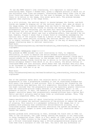
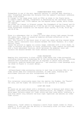
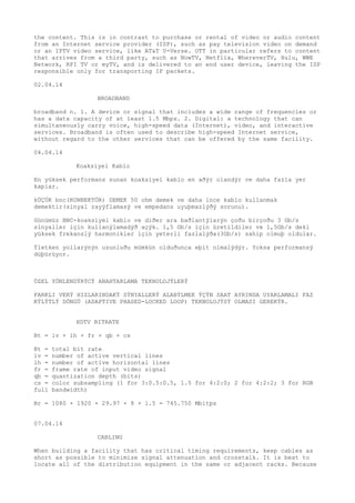
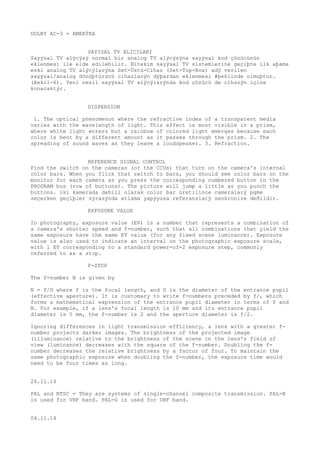
![Konuya fiziksel olarak (kaydýrma hareketi ile) yaklaþýldýðý zaman(geniþ açý)
yanyana olan cisimler birbirinden uzaklaþýrlar. Ýleri optik kaydýrma ile konuya
yaklaþýldýðý zaman (dar açý), perspektif farký oluþmuþtur. Bunda tam tersi
cisimler birbirinden uzaklaþýyorlarmýþ gibi görünür. Geniþ açýda da , yanyana
olan cisimler birbirinden uzaklaþýyormuþ gibi gözükür.
24.09.12
kamerayý saða sola kaydýrma: truck or crab right-left(bu kavram bazen tracking
shot olarak adlandýrýlýr.)
kamerayý yukarý-aþaðý kaydýrma: pedestal(or ped) up-down.
kamerayý ileri-geri kaydýrma: dolly in-out.
kamerayý sað-sol(çapraz hareket ettirme): arc right-left.
vinç yukarý aþaðý: crane up-down.
vincin yanlamasýna kaymasý: tonguing. tongue right-left.
Main article: Retina
The retina consists of a large number of photoreceptor cells which contain
particular protein molecules called opsins. In humans, two types of opsins are
involved in conscious vision: rod opsins and cone opsins. (A third type,
melanopsin in some of the retinal ganglion cells (RGC), part of the body clock
mechanism, is probably not involved in conscious vision, as these RGC do not
project to the lateral geniculate nucleus (LGN) but to the pretectal olivary
nucleus (PON).[5]) An opsin absorbs a photon (a particle of light) and transmits
a signal to the cell through a signal transduction pathway, resulting in
hyperpolarization of the photoreceptor. (For more information, see Photoreceptor
cell).
Rods and cones differ in function. Rods are found primarily in the periphery of
the retina and are used to see at low levels of light. Cones are found primarily
in the center (or fovea) of the retina.[citation needed] There are three types
of cones that differ in the wavelengths of light they absorb; they are usually
called short or blue, middle or green, and long or red. Cones are used primarily
to distinguish color and other features of the visual world at normal levels of
light.[citation needed]
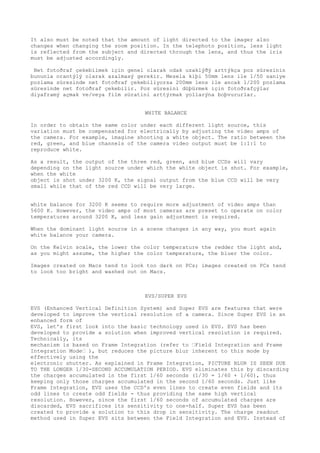
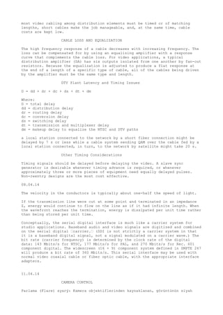
ILLUMINATION
Home Illumination Study, details results of a comprehensive study of ambient
light levels in typical television viewing locations. This information is useful
for determining how bright a television picture needs to be to provide a
satisfactory viewing experience. Brightness has a direct impact on the energy
consumption of the television.
IMAGE SIZE
The image size depends on image size, so lenses intended for 2/3 inch and 1/2
inch cameras have different focal lengths.
Angle of view can be derived from the following equation. w = 2tan-1 y/2f y =
image size, w = angle of view, f = focal length.
WHITE BALANCE
White balance (refer to ’White Balance’ ) electrically adjusts the amplitudes of
the red (R) and blue (B) signals to be equally balanced to the green (G) by use
of video amplifiers.We must keep in mind that using electrical amplification
will result in degradation of signal-to-noise ratio.
DEPTH OF FIELD FACTORS
1)The larger the iris F-number (refer to ’F-number’ ) (stopping down the amount
of incident light), the deeper the depth of field.
2)The shorter the focal length of the lens, the deeper the depth of field.
3)The further the distance between the camera and the subject, the deeper the
depth of field.](https://image.slidesharecdn.com/broadcasteriyeri-141215010307-conversion-gate02/85/Broadcaster-Notes-4-320.jpg)
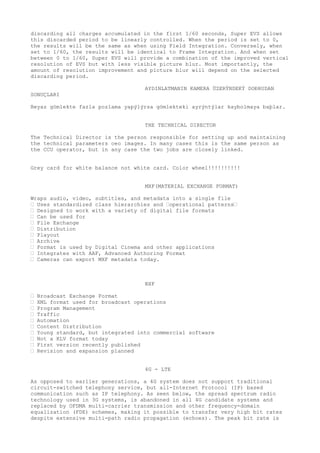
![further improved by smart antenna arrays for multiple-input multiple-output
(MIMO) communications.
3GPP Long Term Evolution (LTE)[edit]
See also: LTE Advanced above
Telia-branded Samsung LTE modem
The pre-4G 3GPP Long Term Evolution (LTE) technology is often branded "4G-LTE",
but the first LTE release does not fully comply with the IMT-Advanced
requirements. LTE has a theoretical net bit rate capacity of up to 100 Mbit/s in
the downlink and 50 Mbit/s in the uplink if a 20 MHz channel is used “ and more
if multiple-input multiple-output (MIMO), i.e. antenna arrays, are used.
LTE, an initialism of long-term evolution, marketed as 4G LTE, is a standard for
wireless communication of high-speed data for mobile phones and data terminals.
It is based on the GSM/EDGE and UMTS/HSPA network technologies, increasing the
capacity and speed using a different radio interface together with core network
improvements.[1][2] The standard is developed by the 3GPP (3rd Generation
Partnership Project) and is specified in its Release 8 document series, with
minor enhancements described in Release 9.
The world's first publicly available LTE service was launched by TeliaSonera in
Oslo and Stockholm on December 14, 2009.[3] LTE is the natural upgrade path for
carriers with both GSM/UMTS networks and CDMA networks such as Verizon Wireless,
who launched the first large-scale LTE network in North America in 2010,[4][5]
and au by KDDI in Japan have announced they will migrate to LTE. LTE is,
therefore, anticipated to become the first truly global mobile phone standard,
although the different LTE frequencies and bands used in different countries
will mean that only multi-band phones will be able to use LTE in all countries
where it is supported.
LTE is a standard for wireless data communications technology and an evolution
of the GSM/UMTS standards. The goal of LTE was to increase the capacity and
speed of wireless data networks using new DSP (digital signal processing)
techniques and modulations that were developed around the turn of the
millennium.
The LTE specification provides downlink peak rates of 300 Mbit/s, uplink peak
rates of 75 Mbit/s and QoS provisions permitting a transfer latency of less than
5 ms in the radio access network. LTE has the ability to manage fast-moving
mobiles and supports multi-cast and broadcast streams.
OFDMA for the downlink, SC-FDMA for the uplink to conserve power
Enhanced voice quality[edit]
To ensure compatibility, 3GPP demands at least AMR-NB codec (narrow band), but
the recommended speech codec for VoLTE is Adaptive Multi-Rate Wideband, also
known as HD Voice. This codec is mandated in 3GPP networks that support 16 kHz
sampling.[30]
Fraunhofer IIS has proposed and demonstrated Full-HD Voice, an implementation of
the AAC-ELD (Advanced Audio Coding “ Enhanced Low Delay) codec for LTE handsets.
[31] Where previous cell phone voice codecs only supported frequencies up to 3.5
kHz and upcoming wideband audio services branded as HD Voice up to 7 kHz, Full-
HD Voice supports the entire bandwidth range from 20 Hz to 20 kHz. For end-to-end
Full-HD Voice calls to succeed however, both the caller and recipient's
handsets as well as networks have to support the feature.
05.11.13
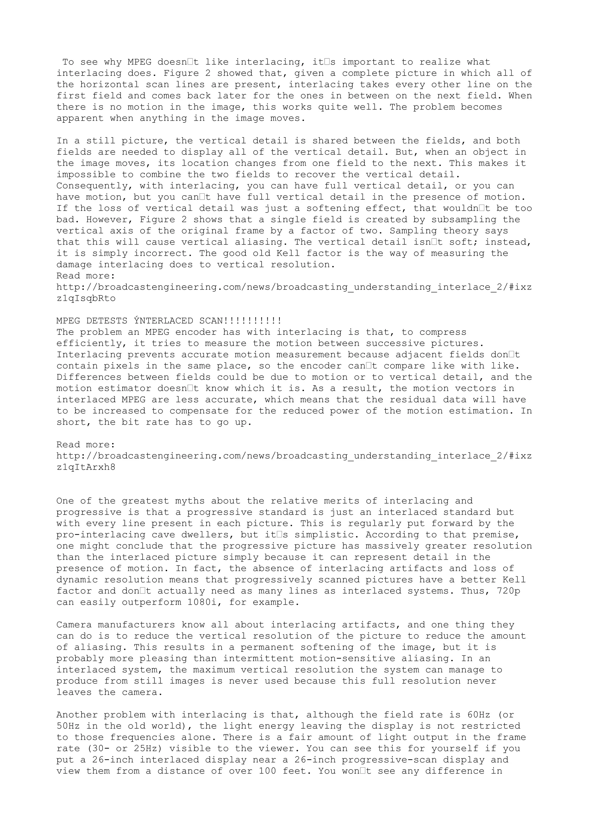
HDC 1400R
Set VF DETAIL to ON to activate the VF detail function to add the detail signal
to sharp edges in the image. You can adjust the signal level (strength) in the
range of 0 to 100% (default 25%). You can adjust the characteristics of the](https://image.slidesharecdn.com/broadcasteriyeri-141215010307-conversion-gate02/85/Broadcaster-Notes-8-320.jpg)
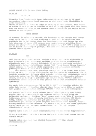
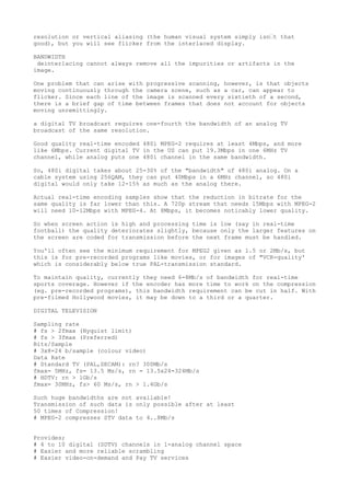
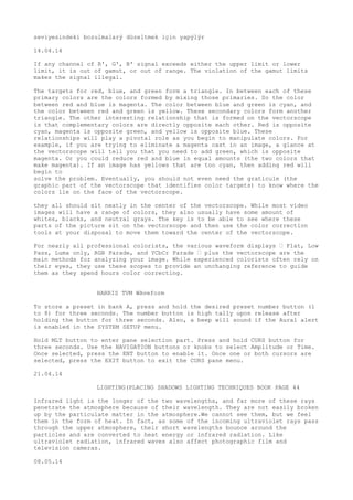
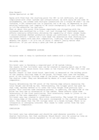
![SDI
1 Voltluk video sinyalinin 8bit derinliðinde beyaz deðeri 235 siyah deðer 16
dýr. Parlaklýk seviyesi 10 bit derinliðinde dijitale çevrildiði zaman beyaz 940,
siyah 64 deðerini alýyor. Renk bileþenlerinde U ve V'de, siyah seviyesi 8 bit
için 128; 10 bit için 512 olur. Renk bileþenlerinin üst ve alt deðerleri 8 bit
sinyalde 16 ile 240 arasýnda deðiþirken, 10 bit sinyalde 64 ile 960 arasýnda
alýnýr.
OFDM modülasyonu tekniðinde ayný frekanstaki taþýyýcýlarýn modülasyondan sonra
üst üste bindirilebilmesi sayesinde daha dar bantta daha yüksek hýzlarda bilgi
iletilebilir.
Dijital kameralarda sadece ayar ve kontrol bilgileri iþlemci denetimindedir,
görüntü bilgileri ve görüntü düzeltme sinyalleri baðýmsýz çiplerde iþlenirler.
04.02.14
PTZ
A pan“tilt“zoom camera (PTZ camera) is a camera that is capable of remote
directional and zoom control.
In television production PTZ controls are used with professional video cameras
in television studios and referred to as camera robotics. These systems can be
remotely controlled by automation systems. The PTZ controls are generally sold
separately without the cameras.
PTZ is an abbreviation for pan, tilt, and zoom and reflects the movement options
of the camera. Other types of cameras are ePTZ where a megapixel camera zooms
into portions of the image and a fixed camera that remains in one position and
does not move. Surveillance cameras of this type are often connected to a DVR to
control the movement and record the video.
Auto tracking[edit]
An innovation to the PTZ camera is a built-in firmware program that monitors the
change of pixels generated by the video clip in the camera. When the pixels
change due to movement within the cameras field of view, the camera can actually
focus on the pixel variation and move the camera in an attempt to center the
pixel fluctuation on the video chip. This process results in the camera
following movement. The program allows the camera to estimate the size of the
object which is moving and distance of the movement from the camera. With this
estimate the camera can adjust the cameras optical lens in and out in an attempt
to stabilize the size of pixel fluctuation as a percentage of total viewing
area. Once the movement exits the cameras field of view the camera automatically
returns to a pre-programmed or "parked" position until it senses pixel variation
and the process starts over again.
07.02.14
Chromatic Aberration
chromatic aberration; CA; chromatic distortion; CD n. A lens defect
that bends light rays of different colors at different angles due to their
different indexes of refraction. As a result, a single lens will actually
create multiple images, each of a different wavelength (color) of light
and each offset slightly from the others, creating a blurred or colorfringed
effect.
10.02.14
Kompozit'ten SDI'ya Çevirici](https://image.slidesharecdn.com/broadcasteriyeri-141215010307-conversion-gate02/85/Broadcaster-Notes-10-320.jpg)
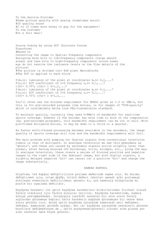
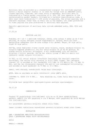
![Marka Kramer. 2 SDI çýkýþ var. 1 kompozit video, BNC baðlantý ile 1Vpp/75ohm; 1
s-video, 1Vpp, 4-pin baðlantý ile 0.3Vpp/75ohm elde edilir. Çýkýþta 2 adet SDI
SMPTE-259M arabirimi olup, BNC baðlantý ile ITU-R BT.601 koþullarýna uyum
saplanýr. 10 bit dijital çöznürlüðe sahip ürün, 5 MHz bant geniþliði sunuyor.
SNR 57 dB, K faktörü %0.2'nin altýnda. Renk-ton gecikmesi 15 nanosaniyeden kýsa
olup, RS-232 üzerinden parlaklýk, kontrast, renk, doygunluk ayarlarý
yapýlabiliyor.
S-VIDEO
Separate Video,[1] commonly known as S-Video, Super-video and Y/C, is a
signalling standard for standard definition video, typically 480i or 576i. By
separating the black-and-white and colouring signals, it achieves better image
quality than composite video, but has lower colour resolution than component
video.
12.02.14
ARRI ULTRA WIDE ZOOM TESTÝ
UWZ 33.7mm görüntü dairesine sahip ve geniþ sensörlü dijital kameralar.
Bozulmayý en aza indiren telesentrik optik tasarým. Bir lensin ortasýnda
normalde parlak bir nokta olup kenarlara doðru koyulaþýrken UWZ'de bu görülmez.
Çok geniþ bir binanýn bir ucundan diðer ucuna pan yapýldý ve düz çizgilerde bir
bozulma olmadý.
14.02.14
PILLARBOXING
Pillarboxing (reversed letterboxing) is the display of an image within a wider
image frame by adding lateral mattes (vertical bars at the sides); for example,
a 1.33:1 image has lateral mattes when displayed on a 16:9 aspect ratio
television screen.
QoS
Quality of service is the ability to provide different priority to different
applications, users, or data flows, or to guarantee a certain level of
performance to a data flow. For example, a required bit rate, delay, jitter,
packet dropping probability and/or bit error rate may be guaranteed.
LIVE STREAMING
Live streaming, which refers to content delivered live over the Internet,
requires a camera for the media, an encoder to digitize the content, a media
publisher, and a content delivery network to distribute and deliver the content.
AKTÝF AYGIT
Kendi güç beslemeleri olan aygýtlardýr(LAN Switch).
19.03.14
OTT(Over the top)
Over-the-top content (OTT) refers to delivery of video, audio and other media
over the Internet without a multiple system operator being involved in the
control or distribution of the content. The provider may be aware of the
contents of the Internet Protocol packets but is not responsible for, nor able
to control, the viewing abilities, copyrights, and/or other redistribution of](https://image.slidesharecdn.com/broadcasteriyeri-141215010307-conversion-gate02/85/Broadcaster-Notes-11-320.jpg)
![GHOSTING
Digital ghostinG :
Ghosting is not specific to analog transmission. It may appear in digital
television when interlaced video is incorrectly deinterlaced for display on
progressive-scan output devices.
23.07.14
SCRAMBLER
a scrambler is a device that transposes or inverts signals or otherwise encodes
a message at the transmitter to make the message unintelligible at a receiver
not equipped with an appropriately set descrambling device. Whereas encryption
usually refers to operations carried out in the digital domain, scrambling
usually refers to operations carried out in the analog domain.
GATEWAY
Roughly, it refers to systems called as protocol converter!!
PROXY SERVER
In computer networks, a proxy server is a server (a computer system or an
application) that acts as an intermediary for requests from clients seeking
resources from other servers.
-Alice : Ask Bob what the current time is
-Proxy : what is the current time Bob?
-Bob : The time is 7pm.
-proxy : Time is 7pm.
01.08.14
SDI STANDARDS
SMPTE 292M - HD-SDI - 1998[2] - 1.485 Gbit/s, and 1.485/1.001 Gbit/s - 720p,
1080i
SMPTE 372M - Dual Link HD-SDI - 2002[2] - 2.970 Gbit/s, and 2.970/1.001 Gbit/s
1080p
SMPTE 424M - 3G-SDI - 2006[2] - 2.970 Gbit/s, and 2.970/1.001 Gbit/s
1080p
composite-encoded (NTSC or PAL)!!!!!
LTC
LTC care:
Avoid percussive sounds close to LTC
Never process an LTC with noise reduction, eq or compressor
Allow pre roll and post roll
To create negative time code add one hour to time (avoid midnight effect)
Always put slowest device as a master
05.08.14
ANCILLARY DATA(SDI)
Like SMPTE 259M, SMPTE 292M supports the SMPTE 291M standard for ancillary data.](https://image.slidesharecdn.com/broadcasteriyeri-141215010307-conversion-gate02/85/Broadcaster-Notes-15-320.jpg)


The document discusses several technical issues that arise with interlaced video formats compared to progressive formats. It explains that with interlacing, full vertical detail or motion can be achieved but not both, and that this causes problems for video compression algorithms. It also notes that while progressive formats avoid these interlacing artifacts, moving objects may appear flickering. Overall, the document analyzes various technical tradeoffs between interlaced and progressive video.


![Tv 101[1]](https://cdn.slidesharecdn.com/ss_thumbnails/tv1011-12648274753543-phpapp01-thumbnail.jpg?width=640&height=640&fit=bounds)


