1. Electus Distribution Reference Data Sheet: CCDCAMS.PDF (1)
UNDERSTANDING & USING CCD CAMERAS
Compact video cameras using CCD (charge-coupled
device) sensors are now widely available at low cost, and as
a result they find many uses around the home, office and
factory. Typical uses including monitoring babies, keeping an
eye on kids playing in the yard or swimming pool, viewing
callers at the front door and general surveillance of office
and factory areas.
In this data sheet we’ll explain how CCD cameras work,
and give you the information you’ll need to select the most
appropriate camera (and lens) for any particular job and get
the best performance from it.
CCD imagers
transferred from each one to the one below. It’s like a
traditional ‘bucket brigade’.
Along the bottom of all the columns, there’s yet another of
these ‘bucket brigade shift registers’ — only this time it’s
horizontal. So by pulsing the transfer gates linking the
bottom row of charge-transfer elements, the charges in
them can be shuffled out of the image array, in serial order.
Here they’re passed through a charge-to-voltage amplifier
stage to produce the output video signal. Fig.2 shows the
overall charge flow paths in the image sensor array.
Getting back to the basic imager cell of Fig.1 for a moment,
you’re probably wondering what that overflow gate and
drain are for. Basically, they’re to prevent the sensor
elements from accumulating too much charge, if the light
falling on them is too great (i.e., over exposure).
The idea here is that the overflow gate is held at a voltage
At the heart of this type of camera is the CCD imager , a
specialised type of integrated circuit (IC) which is located
just behind the camera’s lens. The lens focuses a small
image of the scene in front of it directly onto the
CCD imager chip, which is behind an optical glass
window in its package. The CCD imager then ‘scans’
the image, and with the help of a few support chips
generates a complete standard video signal from it,
ready to feed into your TV, video monitor or VCR.
The detailed operation of a CCD imager chip is
fairly complex, but here’s a simplified explanation of
how they work.
Over the active image-sensing area of the chip,
there’s an array of tiny sensor cells, each typically
measuring 10 x 5um (micrometres) or less. The
array of a typical CCD sensor has 297,984 of these
cells, arranged in 582 horizontal rows and 512
vertical columns.
Inside each cell there’s a light sensitive element —
essentially a very tiny photodiode — together with
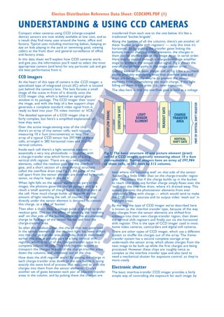
Fig.1: The basic structure of one picture element (pixel)
a charge-transfer area which forms part of a long
cell of a CCD imager, typically measuring about 10 x 6um
vertical shift register. There are also two control
(micro-metres). Typical imagers have an array of 297,984
elements, called the readout gate and the overflow
of these cells, in 582 rows by 512 columns.
gate, and a short section of a long vertical structure
called the overflow drain (see Fig.1). All parts of the
level where the ‘retaining wall’ on that side of the sensor
cell apart from the sensor element are covered by metalli‘bucket’ is a little lower than on the charge-transfer region
sation, so they’re ‘kept in the dark’.
side. This means that if the charge builds up in the bucket
When light falls on the sensor element (as part of the
to reach that level, any further charge simply flows over the
image), the photons generate charge carriers and as a
‘wall’ into the overflow drain, where it’s drained away. This
result a small quantity of charge builds up in that part of
system prevents the photosensor elements from ever
the cell. How much charge builds up depends on the
completely filling with charge — which would tend to make
amount of light reaching the cell, of course. The area
the CCD imager saturate and its output video ‘wash out’ in
directly under the sensor element is designed to contain
highlight areas.
this charge, as a kind of ‘bucket’.
By the way the type of CCD imager we’ve described here
Then after a short time, a voltage pulse is applied to the
is known as the interline transfer type, because of the way
readout gate. This has the effect of lowering the ‘retaining
the charges from the sensor elements are shifted first
wall’ on that side of the bucket, allowing the accumulated
sideways into their own charge-transfer region, then down
charge to flow out of the sensor bucket and into the
the vertical shift registers and finally out via the horizontal
charge-transfer area.
shift register. This is the type of CCD imager used in most
home video cameras, camcorders and digital still cameras.
So after the readout pulse, the charge that was generated
in the sensor element by the incident light has been shifted
There are other types of CCD imager, which use a different
into the charge-transfer area alongside. And as mentioned
system to shuffle the charges out of the array. The frameearlier this area is actually part of a long vertical shift
transfer system has a second complete storage array
register, which links all of the charge-transfer areas in a
underneath the sensor array, which allows charges from the
complete column of cells. This shift register is used to
next image to be built up while the first charges are being
transport the charges in each of the charge-transfer areas
processed. However these chips are roughly twice as
down the columns, and ultimately out of the chip.
complex as the interline transfer type and also tend to
need a mechanical shutter for exposure control, so they’re
How does the shift register work? By passing the charge in
more costly.
each charge-transfer area down to the one below it, using
exactly the same kind of process that was used to shift the
Electronic shutter
charges into them from the sensor elements. There’s
another set of gates between each pair of adjacent transfer
The basic interline-transfer CCD imager provides a fairly
areas in the column, and by pulsing these the charges are
simple way of controlling the exposure for each image: by
2. Electus Distribution Reference Data Sheet: CCDCAMS.PDF (2)
varying the length of time that the charge can
build up in each sensor element, before it’s
shifted out into the charge-transfer region. So by
adjusting the timing of the readout pulses, the
control circuitry effectively controls the exposure
time.
This property of CCD imagers is usually
described as their electronic shutter , and most
CCD cameras use it to provide a simple means of
allowing the camera to deliver clear video signals
over a fairly wide range of lighting levels.
With most CCD imagers, this ‘automatic
electronic shutter’ or A E S function has an
effective range from about 10us (1/100,000th of a
second) up to almost 20ms (1/50th of a second)
— the video field period. This gives an exposure
control range of almost 2000:1.
B&W or colour
The photosensor elements of a CCD imager
respond to any light in a fairly wide range of
wavelengths. In other words, they can’t
distinguish between colours. So a basic CCD
imager forms what is essentially a B&W (black
and white) video camera.
Fig.2: A simplified view of the structure of an interline-transfer
CCD imager, showing the way pixel data flows from the
Two different systems are used to produce a
photosensors first into the vertical shift registers, then out of
CCD c o l o u r camera. In the single chip system
the chip via the horizontal shift register at the bottom.
used in most low cost video cameras, camcorders
and digital still cameras, tiny strips of colour filter
material are laid on the top of the CCD imager,
same image. This three-chip colour system can deliver
covering the sensor columns in a repeating green-red-blue
higher quality colour signals than the single-chip system, but
sequence. This restricts each column of sensor elements to
tends to be much more expensive because of the three
responding primarily to the colour passed by that filter, so
imagers and more complex optical system. It’s used mainly
that the video signal that emerges from the imager has
in broadcasting and professional TV cameras.
colour information multiplexed into it. All of the video is
used by the processing circuitry to generate the luminance
Imager size
signal, but the information corresponding to each trio of
The majority of domestic and industrial CCD video
sensor bits can also be used to generate the
cameras use one of two main sizes of CCD imager. These
chrominance (colour) signal.
are usually called the 1 / 3 ” type and the 1 / 4 ” type, and
The alternative way of producing a CCD colour camera is
both are made in either B&W or colour versions. Other
to use three separate CCD imagers, each receiving its light
sizes are made, including a smaller 1/5” type and a larger
via a filter for one of the three primary colours. The three
1/2” type, but they’re much less common.
imagers are mounted around an optical prism/splitter
The active image size of a nominal 1/3” CCD imager is
system behind the lens, so that all three receive exactly the
actually 4.8 x 3.6mm, while that of a nominal 1/4”
imager is 3.6 x 2.7mm. In each case the larger of
the two dimensions is image width. Note that the
ratio of the two is 1.33:1 in each case. This is
known as the aspect ratio , and matches that of a
standard CCIR/PAL TV signal (usually expressed as
4:3).
Resolution
Fig.3: The spectral response of a typical CCD imager (B&W),
showing that there’s still significant sensitivity for infra-red
radiation.
Broadly speaking, the image clarity or ‘picture
sharpness’ delivered by a CCD camera depends on
its resolution — how well it reproduces or
‘resolves’ fine details in the image. However there
are a number of ways of describing the resolution,
which can make things a bit confusing.
For example there’s the basic resolution of the
camera’s CCD imager: how many rows and
columns of sensor elements it uses, which determines the number of picture elements or pixels
that it uses to analyse the image.
Most low cost CCD video cameras use an imager
with a basic resolution of either 512 or 500
columns across the picture, and 582 rows down
the picture. This gives roughly one row of sensor
pixels for each active line of a nominal 625-line
video image, and the potential of 500 or more
3. Electus Distribution Reference Data Sheet: CCDCAMS.PDF (3)
pixels along each line.
But the final horizontal resolution of the image isn’t
determined only by the CCD imager. It’s also influenced by
the frequency response of the other chips used to process
the video signal from the imager, and these inevitably
reduce the effective resolution to some extent.
To give you a better idea of the final image resolution from
a camera, manufacturers usually also specify an effective
horizontal resolution figure as well as the imager’s raw pixel
figures. This resolution figure is usually quoted in terms of
the number of alternating black and white lines that can be
resolved across the width of the image — i.e., along each
line. This figure usually turns out to be rather lower than
the potential 500- or 512-line resolution you’d expect from
the imager: typical cameras provide figures ranging from
330 to 420 lines. However a figure of 400 lines or more
will generally give images that most people find quite clear
and ‘sharp’.
Note, though, that the final clarity of the images produced
by any camera will also depend on the performance of the
video monitor or TV receiver it’s displayed on. If the
monitor has relatively poor video response, the image from
the best camera will still look ‘soft’ or ‘furry’.
Spectral response
The sensor elements of a basic CCD imager (B&W)
respond to wavelengths covering the complete range of
visible light, and beyond (see Fig.3). The peak response is
usually between about 500 and 550nm (nanometres),
corresponding to green-yellow light. However the sensors
often still have 20% or more of their peak sensitivity at
780nm, which is the start of the infra-red (IR) part of the
spectrum and outside the range visible to the human eye.
This wide spectral sensitivity of CCD imagers has both
advantages and disadvantages. On the plus side, it means
that CCD cameras can be used with IR illumination to
monitor areas that seem to the human eye to be in total
darkness. This makes them very suitable for surveillance.
On the other hand, the fact that a CCD imager responds
to IR as well as visible light can degrade image quality when
a camera is viewing a scene where there’s significant IR
radiation as well as visible light. This is because many lenses
have a different focal length at different wavelengths — so a
focus setting that’s correct for visible light tends to result
in a defocussed (blurry) IR image, and vice-versa.
So with many CDD cameras, the only way to get a really
sharp and clear image of some scenes is to use an I R r e j e c t i o n f i l t e r to block out the IR components in the
image. This tends to be more of a problem with B&W
CCD cameras than with colour cameras, as the colour
filter stripes tend to reduce the imager sensitivity to IR
wavelengths. However some colour cameras still have a
significant sensitivity to IR, especially if they’ve been
designed to be sensitive down to very low light levels.
CCD cameras
Currently there are two broad types of low cost video
camera based on CCD imagers: the ‘naked board’ type,
usually with a built-in lens, and the fully encased type. The
latter can have either a built-in lens or be designed to
accept replaceable screw-in lenses. Both types are available
in either B&W or colour, and the fully encased type often
consists of a board-type camera in a sturdy but compact
metal case, fitted with a lens mount at the front and
power/output connectors at the rear.
Whether of the naked-board or encased type, most of the
latest CCD cameras are fully automatic in operation and
have virtually no manual controls or adjustments apart from
focusing via the lens mounting. Exposure control is
automatic and based on the CCD imager’s AES function.
This typically copes with a 2000:1 range in light level, and
allows the use of low cost fixed-aperture lenses. If a
camera needs to operate at a very high light level, a
neutral-density filter can often be used to prevent overload.
When a CCD camera does need to be used where lighting
levels vary over a range of much wider than 2000:1, an
auto iris lens can be used to allow it to cope with the
larger range. These lenses are not cheap (often costing as
much or more than the camera itself), but they give
somewhat better performance than the AES system. When
such a lens is fitted the camera’s own AES function is often
disabled.
Nowadays both the naked-board and fully enclosed types of
camera are often equipped with an electret microphone
insert and preamplifier, so they deliver an audio signal as
well as the video from the CCD imager.
Some enclosed cameras are also provided with a number of
forward-facing IR emitting LEDs, to give the camera built-in
IR scene illumination. This makes them especially suitable
for covert surveillance work.
Of course IR illuminators (usually just an array of IR LEDs)
are available at quite low cost anyway, so it’s also possible
to use these with cameras that don’t have the inbuilt
illumination, to achieve the same result.
Power supply
Most small CCD cameras are designed to be powered
from a fairly well regulated source of 12V DC (typically
+/-10%). This makes them very suitable for operation
from a battery supply, for example, but they can
malfunction or even be damaged if the voltage rises
much above 13.5V. That’s why it is unwise to attempt
running them from low cost unregulated ‘12V plug pack’
mains adaptors, as the output from these can easily rise
to 16-17V or more.
A small number of cameras do have internal regulation
circuitry and are able to cope with a wider range of
input voltages — say 9-15V. However in general, when
operating any CCD video camera from mains power it’s
safest to use an electronically regulated 12V power
adaptor or power supply.
Fig.4: A lens whose focal length (f)
is long compared with the CCD imager’s
active image width (s) has a narrower viewing
angle than one with a shorter focal length.
Lenses
Naked-board and very compact enclosed CCD cameras
usually come complete with an integral lens and holder,
4. Electus Distribution Reference Data Sheet: CCDCAMS.PDF (4)
fitted directly over the CCD imager on the front of
the board. These lenses are generally one of two
main types: the fixed-focus ‘pinhole’ type or the
adjustable focus three-element type.
The ‘pinhole’ type lens isn’t a true pinhole, but a
low cost single-element lens with a short focal
length and a small fixed aperture (often 2-3mm), so
that it provides a depth of field extending from
about 2m to infinity. However the single lens
element limits image quality, and the small aperture
restricts such cameras to fairly high lighting levels.
Fig.5: It’s easy to work out the width of a scene viewed at
Better image quality is generally available from the
a known distance from the camera, once you know the
type of camera using a three-element lens, not only
width of the CCD imager’s active image area. The
because of the additional elements but also because
CCD-lens distance ‘q’ is effectively equal to the lens focal
of the adjustable focus. The aperture is usually
length, for scenes and objects that are further away than
somewhat greater too, making the camera more
about one metre.
useful at lower lighting levels.
Although the built-in lenses fitted to naked-board
‘wide angle’ effect.
and compact cameras can deliver quite good image quality,
The actual viewing angle of a lens when used with a
much greater flexibility is available from the larger enclosed
particular CCD imager can be found using this expression:
type of camera, which generally offers the ability to use
interchangeable lenses . In most cases these lenses are of
f = 2 x t a n -1 ( s / 2 q )
the screw-in ‘CS’ type, which is a modified version the ‘C
where f is the horizontal angle of view, s is the width of the
mount’ originally developed for 16mm movie film cameras.
CCD sensor’s active image area and q is the distance
The ‘CS’ version is made with a shorter length extending
between the centre of focus of the lens and the CCD
behind the mounting thread, to ensure they clear the CCD
imager plane.
imager.
Note that when the lens is focussed at objects further away
than about 1m, q will be very close to f, the focal length of
Focal length
the lens. So for most purposes you can simply substitute f
Whether they’re built into the camera or are of the
for q in this expression, to give:
screw-in interchangeable type, the key parameter used to
describe camera lenses is their focal length . This is basically
a measure of the spacing needed between the lens’s centre
of focus and its focal plane (here, the active surface of the
CCD imager), when the lens is producing a properly
focussed image of an object at infinity.
The focal length of CCD video camera lenses is usually
given in millimetres (mm), although sometimes the
horizontal viewing angle is given instead.
Viewing angle
Because of the way lenses work, the focal length of a lens
determines how wide an angle it ‘views’, when producing
an image of a certain width — here, the width of the active
image area of the CCD imager it’s being used with.
As Fig.4 shows, the viewing angle is narrower when the
f
lens has a focal length (f) that’s relatively long compared
s
with the active image width of the sensor (s). Conversely
it’s wider when the lens has a relatively short focal length.
So longer focal length lenses tend to give a ‘telephoto’ or
close-up effect, while those with shorter focal length give a
f = 2 x t a n -1 ( s / 2 f )
However this isn’t true if you use the lens to focus on very
close objects, because q then becomes significantly longer
than f. In these cases you need to use the first expression.
Another point to note from these expressions is that a lens
with a particular focal length will give a wider angle of view
with a CCD imager having a larger active
image width, and vice-versa. For example a
lens of 4mm focal length will give a 48°
angle of view with a camera using a 1/4”
CCD imager, but a 62° angle of view with
a camera using a 1/3” imager.
Typically the lenses built into CCD
cameras have a focal length of about
2.5mm, which tends to give a fairly wide
angle of view: around 90° with a 1/3”
imager or 70° with a 1/4” imager.
Cameras designed especially for ‘front
door viewer’ use are fitted with a special
type of lens with a very wide angle of view
— typically 170°, which is almost a
hemisphere. This type of lens is often
called a ‘ fish eye ’.
Scene width
Although it’s handy to be able to visualise the angle of view
of a lens when used with a particular camera and its imager,
often it’s more important to be able to work out the best
lens to use in order to cover a particular scene width , at a
known distance from the camera.
This is also quite easy to work out. As you can hopefully
see from Fig.5, The ratio of scene width W to the camerascene distance D is the same as the ratio between s, the
active width of the CCD imager and q the lens-imager
distance. In other words,
W/D = s/q
And as before q will be almost exactly the same as f the