2. Strength in building technology Uses
Kerkstoel double walls have special advantages
for different applications. Because each ele-
ment is manufactured individually according
to requirements, Kerkstoel double walls are
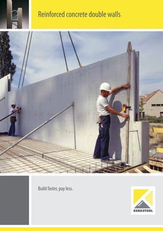
The Kerkstoel reinforced double walls consist of
two slabs of reinforced concrete joined to each
other by lattice girders.
The wall elements are installed on the site ac-
cording to the plan and then filled with concrete.
DIMENSIONS length: up to 8.30 m
height: up to 2.80 m, possibly up to 3.50 m on request
thickness (outside/inside): 19-34 cm (on request 40 to 70 cm)
thickness of the slabs at least 5 cm each
other dimensions on request
WEIGHT approx. 250 kg per m2 with 2 x 5 cm slab thickness
CONCRETE QUALITY at least C25-30
SURFACE suitable for spray plaster or ready to wallpaper on request
the ideal construction method for just about all
building work.
Below you can find some examples of the many
applications.
The result is a solid construction and a strong
base that is virtually a monolithic concrete wall.
Kerkstoel double walls are manufactured in ac-
cordance with the strict standards of the Belgian
conformity certificate and of ISO 9001.
Private homes
Inside and outside walls, the replacement
of brickwork, an alternative for concrete
poured on-site
Large construction projects
Industrial construction, silo walls, tunnels,
underground car parks, supporting walls
Tall walls
Tall walls with a height above 8 m,
can be produced for various uses.
Storey Floors
Façade walls, dividing walls in homes, outside
walls, lifts and stairwells, partition walls
Walls as waterproof constructions
Including basements, water treatment plants,
retaining walls and swimming pools
Prefab-elements
Suitable for spray plaster or ready
to wallpaper as required
Floor slabs
Concrete poured on site
Wall open web beam
Wall reinforcement
3. Kerkstoel thinks of all details Kerkstoel offers technical support
We offer just-in-time logistical and qualified
assembly assistance for the smooth completion
of construction plans.
We draw up a detailed assembly schedule on
the basis of the design of the architect (plan
and cross-section), the stability calculations,
formwork and installation plans.
We develop the production plans and provide
them with all the necessary details, so that
everything goes smoothly and according to
schedule on the site.
CEILING JOINTS BASE PLATE JOINTS FOR VERTICAL JOINTS
for corners
FOR WALL JOINTS
(not reinforced)
(not reinforced)
(not reinforced)(not reinforced)
lattice glider
(not reinforced)
solid wall
(reinforced)
(reinforced)
(reinforced)(reinforced) (reinforced)
double wall
(reinforced)
double wall
open web beam
casing
4. What else does Kerkstoel have to offer? Built-in parts
Because each design has its own specific
properties, Kerkstoel double walls are uniquely
produced according to requirements. Not only
does each wall have its own dimensions and
openings for doors and windows, the built-in
parts for the finishing can also be immediately
provided.
The use of the latest CAD and robot techniques
allows Kerkstoel to produce double walls of
even the most individual design and all this at a
very reasonable cost.
2
6
3
5
1
4
1 Electrical fittings
2 Openings, passageways
3 Pipes for the vertical powering of electrical
installations.
4 Door frames, wooden formwork
5 Windows or wooden formwork
6 Reinforcement for joints with concrete
poured on-site
Kerkstoel offers technical support
1 Provisions for electricity, distribution and
telephone.
2 Openings for: incl. sewers, air-conditioning,
ventilation, etc.
3 Conduit for the ease of electrical
installation
4 Doorway with formwork.
All sizes are possible.
5 Window opening with formwork.
1
3
5
2
4
5. Completely watertight, also at the joints Building in groundwater
The bed plate is utilising a water-resistant concrete.
The outside walls can be of a maximum thickness
and filled with water-resistant concrete.
Kerkstoel’s high quality double wall elements and
the concrete guarantee the complete watertight-
ness of the wall.
The joints are either sealed on the outside or
given a sealing layer.
Kerkstoel double walls are manufactured in
optimal and precision-controlled conditions at
the factory.
Production faults are practically excluded by
using an integrated quality management
system.
The double walls resist any water load, water
pressure and any other form of moisture to
which a building is exposed.
Kerkstoel stands for reliability, and the certainty
that all physical construction properties will be
taken into account.
VERTICAL JOINTS
HORIZONTAL JOINTS
Inner sealing for example
joint with sealing section
open web
beam
bottom foundations
bottom foundations
bottom foundations
bottom foundations
bottom foundations
bottom foundations
Roughen the area of contact
Water retaining plate
Inll concrete (water/cement <0.5)
Swell strip
joint of 3 cm
Roofing
Roughen the area of contact.
This limits the creeping of the con-
crete in relation to the foundations
Always use suitable cement.
The water/cement factor must always
be less than 0.5
The wall must be placed ±3 cm
above the foundations. This means
one can increase the contact area.
Exterior sealing
for example thick coating
Resources for water sealing
Method for good water sealing
6. Transport Preparation of the floor slab
Make sure that the joining reinforcement is
placed correctly with the concreting of the slab,
ensuring that there is sufficient inside space.
Do not use mesh reinforcement as starter bars.
Trace the place where the walls must be
erected with the numbers of the walls on the
ground. The information can be found on the
assembly plan.
Use base plates to accommodate unevenness
of the floor. If not otherwise arranged, make
sure that the joint under the wall is 3 cm.
Four supports are to be levelled out for each
element. (under both surfaces +50 cm from
both ends of the wall.)
Make sure that the crane and the deep-loaders
have unimpeded access to the site. Here you
must take account of possible street obstructi-
ons, the sharpness of bends, parked vehicles,
etc.
The transport vehicles have a length up to 18 m;
the headroom amounts to at least 4 m.
This form of transport is used for walls higher
than 2.80 m.
The permissible ground unevenness is a maxi-
mum of 25 cm over a length of 6 m.
Vertical transport with container is used for
walls with a maximum height to 2.80 m.
With horizontal delivery the base surface of the
lorries must be level.
Vertical transport with carriage
Vertical transport with container
Horizontal transport
7. Unloading of the supplied walls Placing the walls
Three operatives are needed for assembly.
Make sure that with the bringing in of a new
element the elements already in position are not
displaced or damaged.
Gradually lower the element and push any
protruding holding rods to the side. Place the
element in line and up to the adjusting pro-
jections. Make sure that the joints are always
perpendicular 2 cm. The position can still be
corrected with a pry bar to afterwards set the
positions with wedges.
Fix each element with two props on both sides.
Screwed sleeves are provided in the walls. The
holes needed in the floor slab still have to be
drilled.
The crane hooks may only be removed after the
elements have been fixed in place and checked.
Now apply the joint and corner reinforcement.
Do not forget to form the recesses.
Vertical
Sufficiently long hoisting cables must be used
to guarantee an angle of at least 60°. Make sure
that the element is always level. Use a pointer
Horizontal
In exceptional cases the walls are transported
horizontally.
Upon request we can also provide you with
specially designed hoisting hooks with which
one lifts the elements horizontally and stacks
them horizontally next to the lorry.
You must make sure that the ground surface is
suffi ciently stable and level for this. We advise
placing a wooden beam between the hoisting
hooks and the concrete elements to spread
any concentrated loads. One can then pull the
elements vertical with the transport anchors
placed at the factory. We also advise to place a
wooden beam between the hoisting hooks and
the concrete shells.
Always make sure that the chains or cables are
sufficiently long to guarantee an angle of 60°.
The maximum weight per hoist anchor is 2 tons.
>60°
8. Correct concreting Faster, less expensive and perfect construction
More cost-effectiveness
Because no formwork is needed:
■ no rental, storage, investment costs/
depreciations
■ no transport, expensive placing, removal or
cleaning of the formwork
■ less dependent on personnel
■ ideal for single-sided formwork or gap
construction: a possible take-over stipula-
tion is not required
■ greater flexibility
Cost-saving
■ insensitive to settling
■ less sealing material required
■ less transport and crane costs because of
less weight
■ no mortar bed required for assembly
■ no joint problems because of the homo-
genous nature of the concrete deposited
on-site
■ simple connecting of base plate and ceiling
with the joint reinforcement in the infill con-
crete
Extra benefits
■ individual production, geared to each project
■ good acoustic insulation
■ few limitations as regards static possibilities
■ combination of the advantages of concrete
poured on-site and prefab-elements
■ edge formwork for wide slabs already provi-
ded in the wall elements
Shorter construction time
■ lower fi nancing costs
■ production at the factory independent of
weather conditions
■ no waiting times for the removal of form-
work
■ no edge trestle required as support for the
wide slabs
■ built-in elements such as windows, doors,
door frames, cable ducts and electrical
boxes can already be built in at the factory
■ particularly smooth surface areas on the
inside and outside: suitable for spray plaster
■ delivered ready to wallpaper on request: no
traditional plastering necessary
■ just-in-time delivery
Finish the joints as follows:
■ Horizontal joints must be propped up and
formed if necessary.
■ Vertical joints must be formed if the joint is
larger than 1 cm. For this you must use as-
sembly foam.
Reinforce corners using angle bars or wooden
planks. Props can be used for T-joints.
You can place the wide slab before the walls
are concreted. For this the walls must be as-
sembled in a mortar bed or sufficiently wed-
ged. The inner surface of the walls must be
moistened before concreting. Concreting must
take place in accordance with the conditions
provided. The infill concrete must be properly
vibrated.
Important:
■ The permissible concrete pressure must not
exceed 30 kN/m2.
■ We advise you to vibrate for 60 % of the fil-
ling time.
9. These assembly instructions are intended as advice. The infor-
mation is based on current standards and technical approval
and our many years of experience. They are however not binding.
Our assembly supervisors under no circumstances accept the
role and the liability of the authorised supervisor.
This also applies for any employees of our company and our
suppliers on the building site. Variations in colour and surface
with respect to the prospectus material as well as technical and
static changes reserved.
Kerkstoel 2000+ NV
Industrieweg 11
B – 2280 Grobbendonk
T: 014 50 00 31
F: 014 50 15 73
info@kerkstoel.be
www.kerkstoel.be
Kerkstoel 2000+ satisfies the
highest quality standards.
CavityWalls n KerkstoelComfort®Walls n FloorPannels n KerkstoelACTIV®Floors n Floorpannelswithweight-savingcomponents