1. HOW TO READ THE STANDARD
OF EXTERNAL TURNING TOOLS
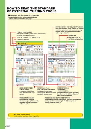
a How this section page is organized
zOrganized according to turning insert shape.
(Refer to the index on the next page.)
FIGURE SHOWING THE TOOLING APPLICATION
uses illustrations and arrows to depict the available
machining applications such as external turning,
copying, facing, and chamfering together with
TYPE OF TOOL HOLDER
cutting edge lead angles.
indicates the first four letters of the order number,
as well as cutting applications. GEOMETRY
TITLE OF PRODUCT BY INSERT TYPE CHIP BREAKER BY
PRODUCT SECTION CUTTING APPLICATION
EXTERNAL TURNING TOOLS
TN TOOL HOLDERS
INSERTS oo
MTJN External turning,
Copying
WP type FH
Finish
SH
Light
MP
Medium
MH
Medium
DTGN External turning
DOUBLE CLAMP type
FH
Finish
SH
Light Medium
MP MH
Medium
B
F1
B
F1
(16) (16,22) (16,22) (16,22) (16) (16) (16) (16)
93° Medium to Medium to
L2 Semi-Heavy Stainless G Class CBN 91° Semi-Heavy Stainless G Class CBN
L1 L2
GH MS R/L L1 GH MS R/L
93° 6°
EXTERNAL TURNING
EXTERNAL TURNING
6° 6°
6°
91°
H1
H2
H1
Right hand tool Right hand tool
H2
holder shown. (16,22) (16,22) (16,22) (16) holder shown. (16) (16) (16) (16)
Stock Dimensions (mm)
* Stock Dimensions (mm)
*2 *2 *1
Order Number Insert Number Order Number Insert Number
R L H1 B L1 L2 H2 F1 Shim Shim Clamp Side Lock Spring Clamp Wrench R L H1 B L1 L2 H2 F1 Shim Shim Clamp Spring Clamp Wrench
Pin Bridge Plate Screw Pin Bridge Screw
MTJNR/L2020K16N a a TNMA 1604pp 20 20 125 31 20 25 WPSTN33 CCP33 CCK13 CPT13 MES2 SLCS105 HKY25R
DTGNR/L1616H16 a a TNMA 1604pp 16 16 100 25 16 20
LLSTN32
LLP23 DCK2211 DCS2 DC0520T TKY15F
HKY40R (LLSTN33)
TNMG TNMG
HKY25R LLSTN32
2525M16N a a TNMM 1604pp 25 25 150 31 25 32 WPSTN33 CCP33 CCK13 CPT13 MES2 SLCS105 HKY40R 2020K16 a a TNMM 1604pp 20 20 125 25 20 25 (LLSTN33) LLP23 DCK2211 DCS2 DC0520T TKY15F
TNGA HKY30R TNGA LLSTN32
2525M22N a a
TNGG 2204pp 25 25 150 38 25 32 WPSTN43 CCP34 CCK14 CPT14 MES3 SLCS106 HKY40R 2525M16 a a TNGG 1604pp 25 25 150 25 25 32 (LLSTN33) LLP23 DCK2211 DCS2 DC0520T TKY15F
* Clamp Torque (N • m) : SLCS105=7.0, SLCS106=7.0 *1 Clamp Torque (Nno. LLSTN33 with 3.18mm thick inserts. When using 3.18mm thick inserts, shim should be ordered separately.
• m) : DC0520T=3.5
*2 Please use shim
PTGN External turning
LL type FH
Finish
SH
Light
MP
Medium
MH
Medium
ETGN External turning
ML type FH
Finish
SH
Light Medium
MP MH
Medium
B
F1
B
(11,16) (16,22) (16,22,27) (16,22)
F1
91° Medium to
Semi-Heavy Stainless G Class CBN 6° (11,16) (16,22) (16,22) (16,22)
L2
6° L1 GH MS R/L 90° Medium Stainless G Class CBN
6° L1
91° 6° 6° Standard MS R/L
Right hand tool
90° * ETGNR/L
H2
H1
H2
H1
holder shown. (16,22,27) (16,22) (11,16,22) (16) 2525M43W
6° Right hand tool holder shown.
Stock Dimensions (mm)
*2
* 2
*1 (16,22) (16,22) (11,16,22) (16)
Order Number Insert Number
Stock Dimensions (mm)
R L H1 B L1 L2 H2 F1 Shim Shim Pin Clamp Clamp Wrench Order Number Insert Number
Lever Screw
R L H1 B L1 H2 F1 Shim Lock Pin Stop Ring Spanner
PTGNR/L1010E11 a a 1103pp 10 10 70 17 10 12 ─ ─ LLCL12S LLCS105 HKY20R
1212F11 a a 1103pp 12 12 80 17 12 16 ─ ─ LLCL12S LLCS105 HKY20R ETGNR/L1212 a a 1103pp 12 12 80 11.5 16 ─ P221US ER2 KY25
1616H16 a a 1604pp 16 16 100 22 16 20
LLSTN32 LLP13
LLCL13 LLCS106 HKY25R 1616H32 a a 1603pp 16 16 100 15.5 20 ─ P322US ER3 KY40
TNMA (LLSTN33) (LLP23)
TNMA
TNMG LLSTN32 LLP13 1616H33 a a 1604pp 16 16 100 15.5 20 ─ P332US ER3 KY40
2020K16 a a 1604pp 20 20 125 22 20 25 (LLSTN33) (LLP23) LLCL13 LLCS106 HKY25R TNMG
TNMM LLSTN32 LLP13 2020K32W a a TNMM 1603pp 20 20 125 19.5 25 EST32 P323WS ER3 KY40
2525M16 a a TNGA 1604pp 25 25 150 22 25 32 (LLSTN33) (LLP23) LLCL13 LLCS206 HKY25R
TNGA EST32 P333WS
2525M22 TNGG 2204pp 25 25 150 28 25 32 LLSTN42 LLP14 LLCL14 LLCS108 HKY30R 2020K33W a a 1604pp 20 20 125 19.5 25 ER3 KY40
a a TNGG
2525M33W a a 1604pp 25 25 150 24.5 32 EST32 P334WS ER3 KY40
3225P22 a a 2204pp 32 25 170 28 32 32 LLSTN42 LLP14 LLCL14 LLCS108 HKY30R
3232P27 a a 2706pp 32 32 170 35 32 40 LLSTN53 LLP15 LLCL25 LLCS508 HKY30R * 2525M43W a a 2204pp 25 25 150 24.5 32 EST43 P434W ER4 KY40
*1 Clamp Torque (Nno. LLSTN33 and shim pin no. LLP23LLCS206=2.2,thick inserts. When using 3.18mm thick inserts, shim and shim pin
• m) : LLCS105=1.5, LLCS106=2.2, LLCS108=3.3, LLCS508=3.3
*2 Please be ordered separately.
should
use shim with 3.18mm
RECOMMENDED CUTTING CONDITIONS RECOMMENDED CUTTING CONDITIONS
Cutting Speed Cutting Speed Cutting Speed Cutting Speed
Work Material Cutting Mode Breaker Grade Work Material Cutting Mode Breaker Grade Work Material Cutting Mode Breaker Grade Work Material Cutting Mode Breaker Grade
(m/min) (m/min) (m/min) (m/min)
P Finish FY NX3035 260 ─ 370 M Finish FH US735 105 ─ 200 P Finish FY NX3035 260 ─ 370 M Finish FH US735 105 ─ 200
Mild Steel Stainless Steel Light 95 ─ 185 Mild Steel Stainless Steel Light 95 ─ 185
( < 180HB)
Light SY NX3035 235 ─ 335 ( < 200HB)
SH US735
( < 180HB)
Light SY NX3035 235 ─ 335 ( < 200HB)
SH US735
Medium MS UE6110 260 ─ 440 Medium MS US735 85 ─ 165 Medium MS UE6110 260 ─ 440 Medium MS US735 85 ─ 165
Finish FH NX3035 200 ─ 280 K Finish R/L-F NX2525 180 ─ 245 Finish FH NX3035 200 ─ 280 K Finish R/L-F NX2525 180 ─ 245
Carbon Steel Carbon Steel
Gray Cast Iron Light 160 ─ 295
Gray Cast Iron Light 160 ─ 295
Alloy Steel Light SH UE6110 210 ─ 355 ( < 350MPa)
MA UC5115 Alloy Steel Light SH UE6110 210 ─ 355 ( < 350MPa)
MA UC5115
(180HB ─ 280HB) (180HB ─ 280HB)
Medium MP UE6110 190 ─ 325 Medium Standard UC5115 160 ─ 295 Medium MP UE6110 190 ─ 325 Medium Standard UC5115 160 ─ 295
(Note) The insert photos are only examples. The letters refer to the chip breaker and the dimension refers to the inscribed circle.
MTJN type inserts A074 ─ A079 DTGN type inserts A074 ─ A079
a : Inventory maintained in Japan. PTGN type inserts A074 ─ A079 ETGN type inserts A074 ─ A079 SPARE PARTS P001
C020 CBN & PCD inserts B028, B029, B053 CBN & PCD inserts B028, B029, B053 TECHNICAL DATA Q001 C021
LEGEND FOR STOCK REFERENCE PAGE PAGE REFERENCE
STATUS MARK FOR APPLICABLE INSERTS · SPARE PARTS
is shown on the left hand indicates reference pages · TECHNICAL DATA
page of each double-page giving details of inserts that are indicates reference pages, including
spread. applicable to the product. the above, on the right hand page of
each double-page spread.
PRODUCT STANDARDS RECOMMENDED CUTTING CONDITIONS
indicates order numbers, for each work material classification, indicates recommended
stock status (per right/left hand), cutting conditions according to the ISO categories for
applicable inserts, dimensions, cutting grades, P, M, and K.
and spare parts.
a To Order : Please specify
zorder number and hand of tool (right/left).
C000
3. EXTERNAL TURNING TOOLS
CLASSIFICATION
External Turning, External Turning, External
Facing Copying Turning
'=63°30'
'=95° '=93° '=90°
Features 72°30'
Tool Holder
Shank Size
EXTERNAL TURNING
(H x W x L)
' ' ' '
a Lever lock type.
LL Holder a
a
ISO standard.
Various holder shapes.
a Suitable for light to
heavy cutting.
a Economical negative insert.
10 x 10 x 70
12 x 12 x 80
16 x 16 x 100
20 x 20 x 125
25 x 25 x 150
32 x 25 x 170 PCLN PWLN PDJN PTGN
32 x 32 x 170 ^ C010 ^ C029 ^ C012 ^ C020
DOUBLE a
a
New double clamp type.
Holds inserts securely.
CLAMP
Holder
a
a
Excellent cutting edge
tolerance.
Economical
negative insert.
a Small insert series.
16 x 16 x 100
20 x 20 x 125
25 x 25 x 150 DCLN DWLN DDJN DVJN DVVN DTGN
32 x 25 x 170 ^ C010 ^ C029 ^ C012 ^ C026 ^ C027 ^ C021
DOUBLE a
a
Double clamp holder type.
Holds inserts securely.
CLAMP
Holder
a
a
Suitable for heavy cutting.
Negative insert.
(For heavy cutting) 32 x 32 x 170
40 x 40 x 200
MCLN
^ C011
WP Holder a
a
Double clamp holder type.
Simple insert exchange.
a Economical
negative insert.
20 x 20 x 125
25 x 25 x 150
32 x 25 x 170
MTJN
^ C020
SP Holder a
a
Screw-on type.
Miniature holder with
7°positive insert.
8 x 8 x 60
10 x 10 x 70
12 x 12 x 80
16 x 16 x 100
20 x 20 x 125
25 x 25 x 150
SCLC SDJC SVJC SDNC SVVC STGC
^ C030 ^ C031 ^ C036 ^ C031 ^ C036 ^ C035
ML Holder a
a
Cam lock type.
Economical
negative insert.
12 x 12 x 80
16 x 16 x 100
20 x 20 x 125
25 x 25 x 150
ETGN
^ C021
C002
5. EXTERNAL TURNING TOOLS
CLASSIFICATION
External Turning, External Turning, External
Facing Copying Turning
'=62°30'
Features '=99° ─95° '=93° '=90°
72°30'
Tool Holder Shank Size
EXTERNAL TURNING
(H x W x L)
' ' '
'
Profile Holder a
a
Screw-on type.
25°rhombic shape insert.
a Possible to machine a
face relief with up to 60º
inclination.
16 x 16 x 100
20 x 20 x 125
25 x 25 x 150
MP Holder a
a
Pin lock type.
35°rhombic shape insert.
a Suitable for recessing.
20 x 20 x 125
25 x 25 x 150
PVJN PVVN
^ C026 ^ C027
MC Holder Clamp-on Type.
a
a Positive insert series.
a Negative insert series.
16 x 16 x 100
20 x 20 x 125
25 x 25 x 150
CTGN
^ C022
AL Holder a
a
Screw-on type.
20° positive insert.
(35° rhombic shape
insert is 15°)
a High rake and good
sharpness.
16 x 16 x 100
20 x 20 x 125 SDJE SVJD SDNE STGE
25 x 25 x 150 ^ C042 ^ C044 ^ C042 ^ C043
TL Holder a
a
Taper lock type.
Excellent finished surface
with round shape insert.
20 x 20 x 125
25 x 25 x 150
32 x 25 x 170
SMALL a Screw-on type.
Tools to be equipped on
TOOLS
a
gang type tool posts.
(Tools for front turning) a Miniature holder with
7°positive insert.
8 x 8 x 125
10 x 10 x 125
12 x 12 x 150
16 x 16 x 150 SCLC-SM SDJC-SM SVJB-SM SDNC-SM SVVB-SM SCAC-SM
^ D008 ^ D009 ^ D010 ^ D009 ^ D011 ^ D008
SMALL a
a
Screw-on type.
Tools to be equipped on
TOOLS
(Tools for back turning)
a
gang type tool posts.
High rigidity due to designing of
vertical insert. (BTA/CTB type)
a Back machining.
(BTA/CTB type)
8 x 10 x 120
10 x 10 x 120
12 x 12 x 120
16 x 16 x 120
C004
6. External Turning, Facing, External Turning,
External Turning Facing Selection Standard
Chamfering Copying Copying
Low Cutting Resistance
'=90° '=75° '=45° '=15° '=0°─ -1° '=10°─
Operation Efficiency
Clamp Rigidity
'
EXTERNAL TURNING
Special Design
Economical
Specialised
(Sharpness)
'
' ' ' '
ee
SXZC
^ C038
e e
PVPN
^ C028
eue
(Positive insert)
(Negative insert)
CTGP CSBN CSDN CSDP CSKN CTFN CTFP
^ C041 ^ C015 ^ C018 ^ C040 ^ C019 ^ C024 ^ C041
e e
STFE
^ C043
u e
TLHR TLHN
^ C047 ^ C047
u
Special Design
u
BTAH CTBH BTVH
^ D012 ^ D013 ^ D014
(Note) e : 1st recommendation. u : 2nd recommendation.
C005
7. EXTERNAL TURNING TOOLS
IDENTIFICATION
y LL Type, Double Clamp Type, WP Type,
SP Type, Profile Holder, AL Type
P C L N R 25 25 M 12
EXTERNAL TURNING
z x c v b n n m ,
zClamp Structure cCutting Angle vInsert Clearance bHand of Tool mTool Length ,Cutting Edge Length (mm)
D Double Clamp Type A 90°Without Offset C 7°Positive R Right Hand (mm) Insert Shape
Inscribed
M
Wedge Lock Type B 75° N Negative L Left Hand D 60 Circle Square Triangular Round Rhombic Rhombic Rhombic
Multiple Clamp Type 80° 55° 35°
D 45°Neutral E 20°Positive N Neutral E 70
P Lever Lock Type 6.00 – – 06 – – –
E 60° F 80
S Screw-on Type 6.35 – 11 – 06 07 11
F 90° H 100
7.94 – 13 – – – –
G 90°With Offset K 125
n Tool Size (mm) 8.00 – – 08 – – –
J 93° M 150
(Height and Width) 9.525 09 16 – 09 11 16
K 75° P 170
8 8 10.00 – – 10 – – –
L 95° Q 180
10 10 12.00 – – 12 – – –
N 62°30´ R 200
12 12 12.70 12 22 – 12 15 –
P 117°30´
xInsert Shape 16 16 15.875 15 27 – 16 – –
Q 105°
C Rhombic 80° 20 20 16.00 – – 16 – – –
S 45°
D Rhombic 55° 25 25 19.05 19 – – 19 – –
T 60°
R Round 32 32 20.00 – – 20 – – –
V 72°30´
S Square 25.00 – – 25 – – –
Z Special
T Triangular 25.40 25 – – – – –
V Rhombic 35° 32.00 – – 32 – – –
W Trigon
X Special Design
C006
8. y ML Type, MC Type
E T G N R 12 12 H 32
EXTERNAL TURNING
z x c v b n n m ,
zClamp Structure xInsert Shape cCutting Angle vInsert Clearance bHand of Tool n Tool Size (mm) mTool Length
C Clamp-on S Square A 90°Without Offset N Negative R Right Hand (Height and Width) (mm)
E Cam Lock T Triangular B 75° P 11°Positive L Left Hand 12 12 F 80
D 45°Neutral N Neutral 16 16 H 100
E 60° 20 20 K 125
F 90° 25 25 M 150
G 90°With Offset
K 75°
S 45°
T 60°
X 100°
,Insert Size (mm)
Insert Size
Symbol Diameter
of Inscribed Thickness
Circle
22 6.35 3.18
32 9.525 3.18
33 9.525 4.76
43 12.70 4.76
C007
9. EXTERNAL TURNING TOOLS
METHOD OF HOLDING
Type (Holder) Structure
Lever Lock b
(LL HOLDER)
zClamp Screw v
EXTERNAL TURNING
b z xLever c
cShim
x
vShim Pin
c bInsert
v
x
z
Double Clamp
b
DOUBLE CLAMP
HOLDER b
zShim v
v xShim Pin n
n c
cSpring
vClamp Bridge
c
z bClamp Screw
x nInsert x
z
Multiple Clamp
v
DOUBLE CLAMP b
HOLDER v c
zShim
(For heavy cutting) xShim Pin
b c
cClamp Screw
vClamp Bridge x
z bInsert
x
z
Wedge Lock n
(WP HOLDER) b
zShim
m
n bv xShim Pin v
m c cPlate
vSpring c
bClamp Bridge x
z
x nClamp Screw
mInsert
z
C008
10. Type (Holder) Structure
Two action double b
clamp v
(PROFILE HOLDER) b
EXTERNAL TURNING
v zInsert
z c
xClamp Screw (1) x
c cSpring
x vClamp Bridge z
bClamp Screw (2)
Cam Lock v
(ML HOLDER)
v zShim x
xLock Pin
z cStop Ring z
vInsert
x
c
c
Screw-on x
SP HOLDER z
AL HOLDER zInsert
z
xClamp Screw
x
Pin lock
b
(MP HOLDER) b z v
zLock Pin z
xShim
x cStop Ring x
vLock Screw
c bInsert c
v
Clamp-on
v
(MC HOLDER) n
n v c zShim
xShim Pin b
cClamp Screw c
b
vClamp Bridge x
z
bInsert
x z
nBreaker Piece
C009