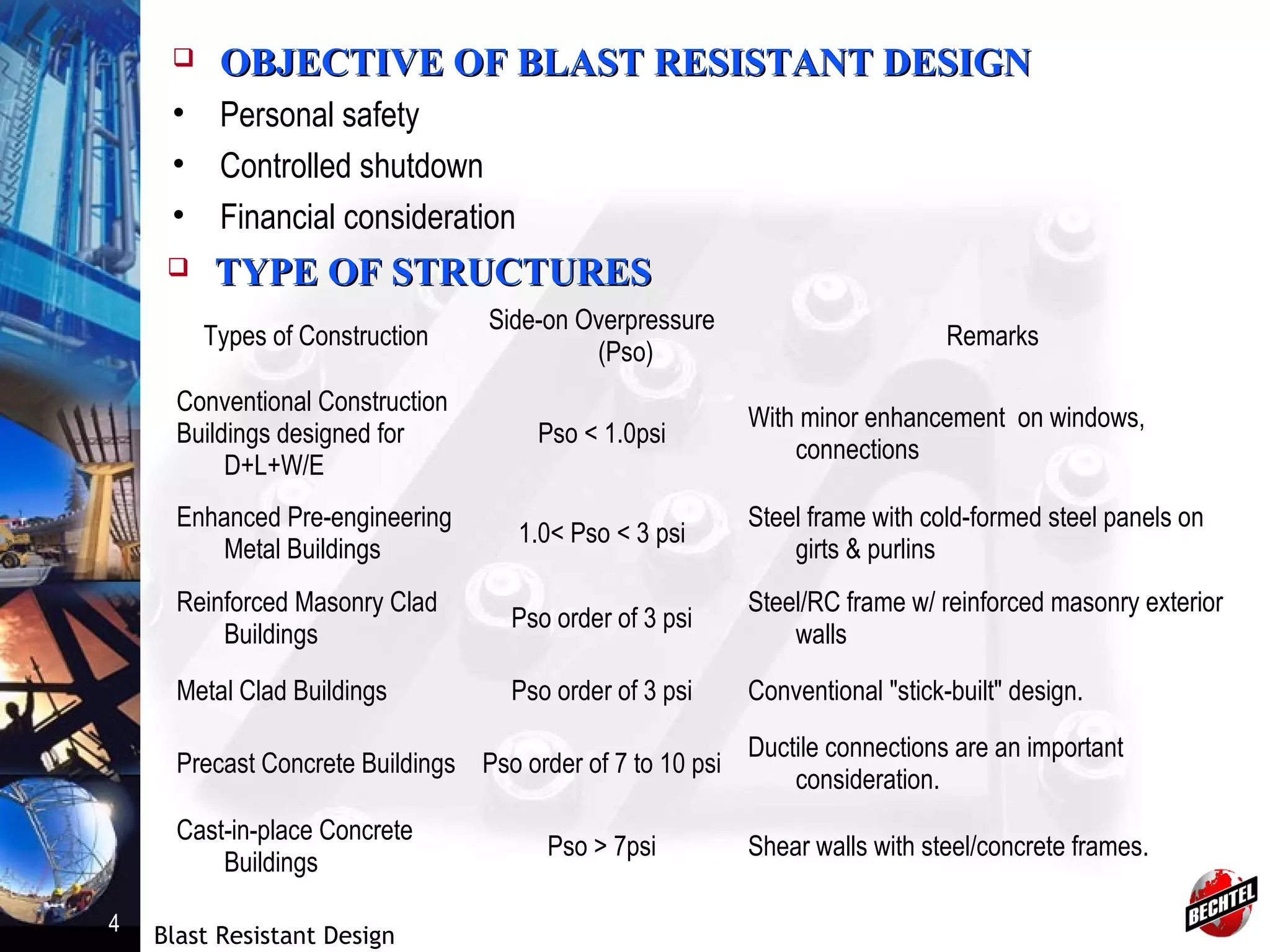
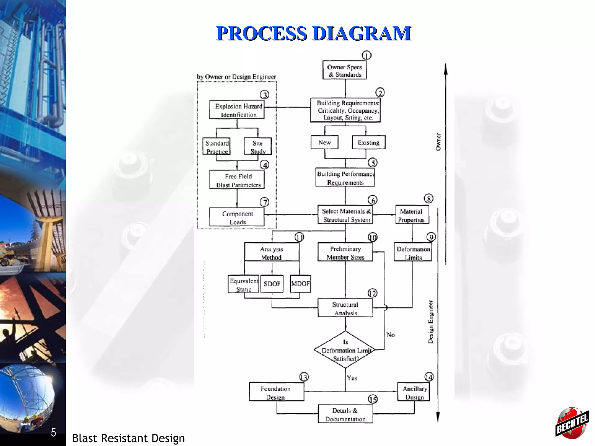
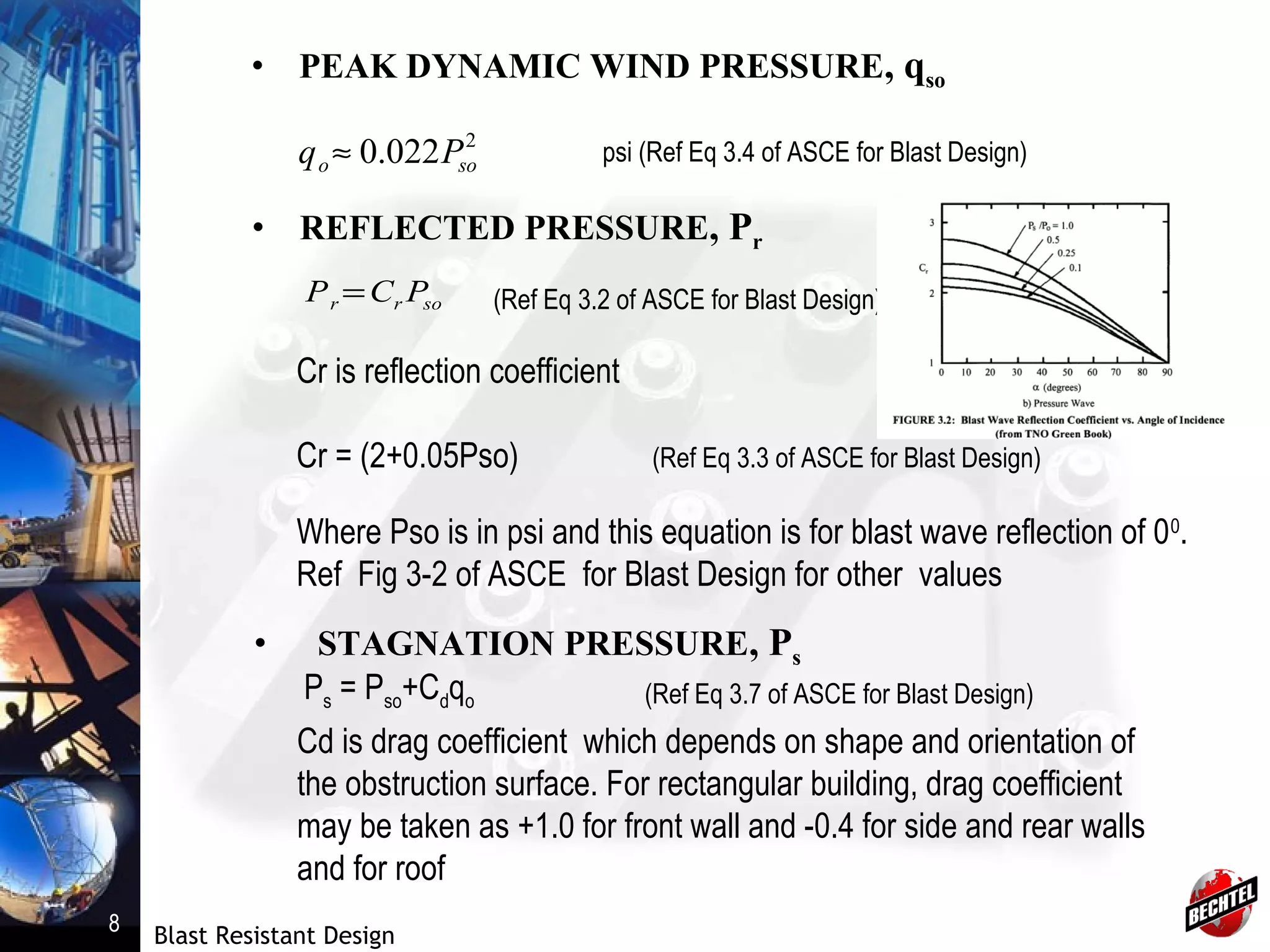
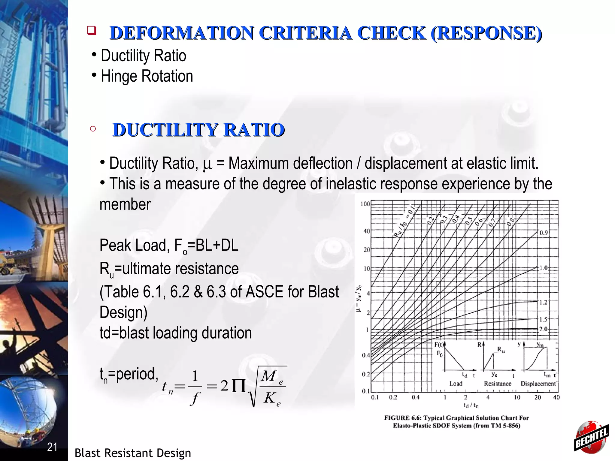
SlideShare a Scribd company logo
Prepared by: Mithun Pal
Civil/Structural Engineer
March 05, 2013
Prepared by: Mithun Pal
Civil/Structural Engineer
March 05, 2013
BP-WND Project – Blast Resistant Design
Single Degree of Freedom System (SDOF)
Blast Resistant Design
2
 CONTENTSCONTENTS
o Introduction
o Objective of Blast Resistance Design
o Types of Blast Resistance Structures
o Design Process Diagram
o Basic Design Information
o Design Process
o References
Blast Resistant Design
3
 INTRODUCTIONINTRODUCTION
• Explosion is a phenomenon associate with sudden release of energy
causing shock wave or pressure wave.
 TYPES OF EXPLOSIONTYPES OF EXPLOSION
• Nuclear Explosion
• Chemical High Explosive
• Accidental Explosions
 TYPES OF EXPLOSION IN PETROCHEMICAL FACILITIESTYPES OF EXPLOSION IN PETROCHEMICAL FACILITIES
• Vapor Cloud Explosion (VCE)
• Pressure Vessel Explosion
• Condensate Phase Explosion
• Dust Explosion
Blast Resistant Design
4
 OBJECTIVE OF BLAST RESISTANT DESIGNOBJECTIVE OF BLAST RESISTANT DESIGN
• Personal safety
• Controlled shutdown
• Financial consideration
 TYPE OF STRUCTURESTYPE OF STRUCTURES
Types of Construction
Side-on Overpressure
(Pso)
Remarks
Conventional Construction
Buildings designed for
D+L+W/E
Pso < 1.0psi
With minor enhancement on windows,
connections
Enhanced Pre-engineering
Metal Buildings
1.0< Pso < 3 psi
Steel frame with cold-formed steel panels on
girts & purlins
Reinforced Masonry Clad
Buildings
Pso order of 3 psi
Steel/RC frame w/ reinforced masonry exterior
walls
Metal Clad Buildings Pso order of 3 psi Conventional "stick-built" design.
Precast Concrete Buildings Pso order of 7 to 10 psi
Ductile connections are an important
consideration.
Cast-in-place Concrete
Buildings
Pso > 7psi Shear walls with steel/concrete frames.
Blast Resistant Design
5
PROCESS DIAGRAMPROCESS DIAGRAM
Blast Resistant Design
6
 BASIC INFORMATIONBASIC INFORMATION
• Client Specification
• Plot Plan and ELP
• Architectural Drawings
• System Vulnerability and Safety Requirements
 DESIGN PROCESSDESIGN PROCESS
• Step 1: Load Calculation
• Step 2: Determination of Member Properties
• Step 3: Model Representation
• Step 4: Trial Member Section
• Step 5: Dynamic Analysis
• Step 6: Deformation Criteria Check
• Step 7: Connection Design
• Step 8: Foundation Design
Note: Damage level determined by Owners.
Blast Resistant Design
7
o FRONT WALLFRONT WALL
• OVERPRESSURE RESULTING FROM INCIDENTAL
PRESSURE, Pso
1. From Client Specification
2. From Fig 2-7 & 2-8 for
of UFC 3-340-02
3
W
R
Z =
Z=Scaled Distance
R=Radial Distance from Charge
W=Charge Weight
 LOAD CALCULATIONLOAD CALCULATION
Blast Resistant Design
8
• PEAK DYNAMIC WIND PRESSURE, qso
2
022.0 soo Pq ≈ psi (Ref Eq 3.4 of ASCE for Blast Design)
• REFLECTED PRESSURE, Pr
sorr PCP = (Ref Eq 3.2 of ASCE for Blast Design)
Cr is reflection coefficient
Cr = (2+0.05Pso) (Ref Eq 3.3 of ASCE for Blast Design)
Where Pso is in psi and this equation is for blast wave reflection of 00
.
Ref Fig 3-2 of ASCE for Blast Design for other values
• STAGNATION PRESSURE, Ps
Ps = Pso+Cdqo (Ref Eq 3.7 of ASCE for Blast Design)
Cd is drag coefficient which depends on shape and orientation of
the obstruction surface. For rectangular building, drag coefficient
may be taken as +1.0 for front wall and -0.4 for side and rear walls
and for roof
Blast Resistant Design
9
FRONT WALL LOADING
• DURATION OF POSITIVE PHASE, td
td also may be provided in client specification
so
w
d
P
I
t
2
=
• IMPULSE, Iw
Measure to define the ability of blast wave to do damage.
From Fig 2-7 & 2-8 for of UFC 3-340-02
Or, by the eqn,
3
W
R
Z =
∫=
dt
w dttPI
0
)(
Blast Resistant Design
10
• SHOCK WAVE VELOCITY, U
ft/s (Ref Eq 3.5 of ASCE for Blast Design)
5.0
)058.01(1130 SOPU +=
• BLAST WAVE LENGTH, LW
(Ref Eq 3.6 of ASCE for Blast Design)dW UtL =
• STAGNATION TIME, tC
(Ref Eq 3.8 of ASCE for Blast Design)dc t
U
S
t <=
3
S = clear distance, the smaller of BH or BW/2
Blast Resistant Design
11
o ROOF LOADINGROOF LOADING
• For roof with slope less than 100
shall not experience any
reflected overpressure and shall experience same side-on
overpressure as side wall
(Ref Eq 3.11 of ASCE for Blast Design)
o SIDE WALLSIDE WALL
SIDE WALL AND ROOF LOADING
Effective side-on overpressure
Pa=CePso+Cdqo
Ce=reduction factor on side-on overpressure
with time and distance
Blast Resistant Design
12
o REAR WALL LOADINGREAR WALL LOADING
•Peak overpressure similar to that of side walls and is calculated by
previous equation
•As its inclusion reduce the overall lateral blast force, many times it
is neglected
o FRAME LOADINGFRAME LOADING
ACTUAL FRAME LOADING
SIMPLIFIED FRAME LOADING
Blast Resistant Design
13
o SUCTION DUE TO NEGATIVE PHASE PULSESUCTION DUE TO NEGATIVE PHASE PULSE
• Peak value of negative phase pressures are generally small
compared with peak positive overpressure, however durations is
longer.
 DETERMINATION OF MEMBER PROPERTIESDETERMINATION OF MEMBER PROPERTIES
Dynamic yield strength
Fdy=(Fy)(SIF) (DIF)
o STRENGTH INCRESE FACTOR, SIFSTRENGTH INCRESE FACTOR, SIF
• Actual yield strength is higher than the values mentioned in codes
and specification. SIF used to account this condition.
• Refer Appendix 5.A of ASCE for Blast Design for SIF values.
o LOAD COMBINATIONLOAD COMBINATION
U(T) = D+aL+B(t)
U(t) = total applied time dependant load
D=static dead load
L=live load, a=reduction factor to live load
B(t)=time dependant blast load
Blast Resistant Design
14
o DYNAMIC INCRESE FACTOR, DIFDYNAMIC INCRESE FACTOR, DIF
• Concrete and Steel material experience an increase in strength
due to rapid strain for blast load. For high strain rate greater load is
required for same deformation.
• Refer Appendix 5.A of ASCE for Blast Design for DIF values.
Blast Resistant Design
15
 MODEL REPRESENTATIONMODEL REPRESENTATION
• Structural member representation
• One-way or two-way action
• Loading distribution for each member
• Connection philosophy
 TRIAL MEMBER SELECTIONTRIAL MEMBER SELECTION
• Dynamic analysis requires trial member sizes
• Nonlinear response properties are calculated from the trial sections
 DYNAMIC ANALYSISDYNAMIC ANALYSIS
• Equivalent Static Method
• Single Degree of Freedom Systems (SDOF)
• Multi-Degree of Freedom System (MDOF)
Blast Resistant Design
16
o EQUIVALENT STATIC METHODEQUIVALENT STATIC METHOD
• Approximate load, called “equivalent wind” is applied to simulate
dynamic response.
• This is not recommended in ASCE for Blast Loading (Cl: 6.3) and
can only be used when structure is far away from blast source and
blast loading acts like wind gust
o SINGLE DEGREE OF FREEDOM SYSEMS (SDOF)SINGLE DEGREE OF FREEDOM SYSEMS (SDOF)
• For common types of structures like single story frames, cantilever wall, box
like building.
• All structures posses more than one degree of freedom which can be
represented as series of SDOF.
• Approximation of equivalent SDOF for structural components requires
deflected shape and strain energy equivalence between actual structure and
SDOF approximation.
Blast Resistant Design
17
17 Linear: Mÿ + Ky = F(t) Meÿ + Key = Fe(t)
Bilinear: Mÿ + R = F(t) Meÿ + Re = Fe(t)
(Lesser of Ky or Rm) KLMMÿ + R = F (t)
Me=KMM Fe=KLF Ke=KLK Re=KLR KLM=KM/KL
Actual structure Equivalent SDOF
TYPICAL STRUCTURAL REPRESENTATION OF EQUIVALENT SDOF SYSTEM
Blast Resistant Design
18
• SINGLE DEGREE OF FREEDOM (SDOF) METHOD
Equivalent Mass of SDOF system: Me
Me = KMM
KM = Equivalent mass/Total actual mass = Me/M
Equivalent Force of SDOF system: Fe
Fe = KLF
KL = Equivalent force/Total actual force = Fe/F
Equivalent Resistance of SDOF system: Re
Re = KLR
R = Lesser of Ky or Rm
Rm is maximum resistance to
blast load
Blast Resistant Design
19
Blast Resistant Design
20
o MULTI-DEGREE OF FREEDOM SYSEMS (MDOF)MULTI-DEGREE OF FREEDOM SYSEMS (MDOF)
• Shall be used when structural configuration is complex or significant dynamic
interaction between interconnected member can not be avoided.
• Will require computer analysis.
• Finite element analysis shall be performed.
• Software associated with nonlinear analysis should be used (e.g., ANSYS)
• Due to association of nonlinearity with plasticity, there is possibility of large
displacement. Hence direct time integration (time-pressure / load diagram)
method should be used.
• Available commercial computer programs for dynamic nonlinear finite
element analysis suitable for use in blast resistant design are LS-DYNA,
ABAQUS, ADINA, ANSYS, MSC/NASTRAN and FLEX.
Blast Resistant Design
21
 DEFORMATION CRITERIA CHECK (RESPONSE)DEFORMATION CRITERIA CHECK (RESPONSE)
• Ductility Ratio
• Hinge Rotation
o DUCTILITY RATIODUCTILITY RATIO
• Ductility Ratio, µ = Maximum deflection / displacement at elastic limit.
• This is a measure of the degree of inelastic response experience by the
member
Peak Load, Fo=BL+DL
Ru=ultimate resistance
(Table 6.1, 6.2 & 6.3 of ASCE for Blast
Design)
td=blast loading duration
tn=period,
e
e
n
K
M
f
t ∏== 2
1
Blast Resistant Design
22
o HINGE ROTATIONHINGE ROTATION
• It relates maximum deflection to span and indicates the degree of instability
present in the critical areas of the member.
Refer Appendix 5.B of ASCE for Blast Design for allowable deformation limits
Ductility
μ=ym/ye
Resistance – Deflection Curve
Blast Resistant Design
23
o BUILDING RESPONSE CRITERIA SPECIFIED BY CLIENTBUILDING RESPONSE CRITERIA SPECIFIED BY CLIENT
Low Response : Localized building/component damage.
Building can be used, the cost of repair is moderate.
Medium Response: Widespread building/component damage.
Building should not be occupied until repaired, the cost of repair is
significant .
High Response: Building/component lost structural integrity.
Building should not be used, the total cost of repairs approaches
replacement of building.
Blast Resistant Design
24
 CONNECTION DESIGNCONNECTION DESIGN
• Plastic hinge developed should be maintained.
• For reinforce concrete design, splices and development lengths must
be provided for the full yield capacities of reinforcement
• For steel design, connections are designed for a capacity somewhat
greater that that of its supported member.
 FOUNDATION DESIGNFOUNDATION DESIGN
• Should be more rigid than conventional structural foundation
• Relative displacement between column and walls need to be
minimized in order to maintain structural integrity. This is accomplished
using grade beams to tie spread footings or pile cap or by using
combined mat foundation.
• Foundation can be analyzed by static analysis and dynamic analysis
Blast Resistant Design
25
o STATIC ANALYSISSTATIC ANALYSIS
• Typically designed for the peak reactions obtained from the superstructure
dynamic analysis.
• The reactions are treated as simultaneous static load, disregarding any time
phase relationship.
• 80% of ultimate net soil-bearing capacity shall be used for shallow foundation
• 80% of ultimate static pile capacity shall be used for deep foundation
• Followings are factor of safety which shall be used for static analysis as per
ASCE
Blast Resistant Design
26
o DYNAMIC ANALYSISDYNAMIC ANALYSIS
• Analysis is complex in nature.
• Shall be used when static analysis is giving uneconomical foundation sizes.
 DESIGN PROCEDURE (SDOF APPROACH)DESIGN PROCEDURE (SDOF APPROACH)
Step 1: Determine blast loads
Step 2: Determine dynamic material properties
Step 3: Determine deformation limits
Step 4: Try structural member sizes
Step 5: Compute resistant – Bending and shear
Step 6: Compute SDOF Equivalent System:
a) Compute effective stiffness
b) Compute equivalent mass
c) Compute period of vibration
Step 7: Compute response by chart
a) Determine ductility from chart
b) Compute maximum deflection ym
c) Compute support rotation
d) Check deformation limit
e) Compute support reaction
Step 8: Resize structural component if deformation limit exceeds.
Blast Resistant Design
27
 REFERENCESREFERENCES
• “Design of Blast Resistant Buildings in Petrochemical
Facilities” First Edition 1997, Second Edition
December 2010
ASCE Task committee
• ARMY TM 5-1300, “Structures to Resist the effects of
accidental Explosions”, November 1990
• ASCE Manual No. 42, Design of Structures to Resist
Nuclear Weapons Effect, 1985
• PIP STC01018, Blast Resistant Building Design
Criteria
• PIP ARS08390, Blast Resistant Door and Frames,
2002
• UFC 3-340-02 Structures to resist the effects of
Accidental Explosions (Dept of Defense USA)
Blast Resistant Design
28
THANKS!
QUESTIONS ?

More Related Content

What's hot

Design of Blast resistance structures
Design of Blast resistance structuresDesign of Blast resistance structures
Design of Blast resistance structures
Sneha Kaira
 
Blast resistant structure
Blast resistant structureBlast resistant structure
Blast resistant structure
Ranjeet Patil
 
Shear wall and its design guidelines
Shear wall and its design guidelinesShear wall and its design guidelines
Shear wall and its design guidelines
Muhammad Zain Ul abdin
 
Tension member
Tension memberTension member
Tension member
Valmik Mahajan
 
Performance Based Design Presentation By Deepak Bashetty
Performance Based Design Presentation By Deepak BashettyPerformance Based Design Presentation By Deepak Bashetty
Performance Based Design Presentation By Deepak Bashetty
Deepak Bashetty
 
DESIGN OF FLAT SLABS
DESIGN OF FLAT SLABSDESIGN OF FLAT SLABS
DESIGN OF FLAT SLABS
sharda university
 
BLAST RESISTANT STRUCTURES
BLAST RESISTANT STRUCTURESBLAST RESISTANT STRUCTURES
BLAST RESISTANT STRUCTURES
Arun Karthik
 
Basic concepts on structural dynamics
Basic concepts on structural dynamicsBasic concepts on structural dynamics
Basic concepts on structural dynamics
Prasad Raju
 
Blast Loading & Its Effect on Structures
Blast Loading & Its Effect on StructuresBlast Loading & Its Effect on Structures
Blast Loading & Its Effect on Structures
Ali Rehman
 
Earthquake resistant design of structures
Earthquake resistant design of structuresEarthquake resistant design of structures
Earthquake resistant design of structures
rvrizul
 
A comparative study of static and response spectrum analysis of a rc building
A comparative study of static and response spectrum analysis of a rc buildingA comparative study of static and response spectrum analysis of a rc building
A comparative study of static and response spectrum analysis of a rc building
Tameem Samdanee
 
Seismic Analysis of Structures - III
Seismic Analysis of Structures - IIISeismic Analysis of Structures - III
Seismic Analysis of Structures - III
tushardatta
 
Dampers
DampersDampers
Dampers
Krishnagnr
 
Seismic Design Basics - Superstructure
Seismic Design Basics - SuperstructureSeismic Design Basics - Superstructure
Seismic Design Basics - Superstructure
Ajit Chandrakant Khanse
 
Static Indeterminacy and Kinematic Indeterminacy
Static Indeterminacy and Kinematic IndeterminacyStatic Indeterminacy and Kinematic Indeterminacy
Static Indeterminacy and Kinematic Indeterminacy
Darshil Vekaria
 
Machine foundation
Machine foundationMachine foundation
Machine foundation
Rakesh Ahirwar
 
Isolated footing design
Isolated footing designIsolated footing design
Isolated footing design
srinu_anduri
 
Compression member
Compression memberCompression member
Compression member
Divya Vishnoi
 
Design wind load
Design wind loadDesign wind load
Design wind load
Sharda University
 
Structural dynamics and earthquake engineering
Structural dynamics and earthquake engineeringStructural dynamics and earthquake engineering
Structural dynamics and earthquake engineering
Bharat Khadka
 

What's hot (20)

Design of Blast resistance structures
Design of Blast resistance structuresDesign of Blast resistance structures
Design of Blast resistance structures
 
Blast resistant structure
Blast resistant structureBlast resistant structure
Blast resistant structure
 
Shear wall and its design guidelines
Shear wall and its design guidelinesShear wall and its design guidelines
Shear wall and its design guidelines
 
Tension member
Tension memberTension member
Tension member
 
Performance Based Design Presentation By Deepak Bashetty
Performance Based Design Presentation By Deepak BashettyPerformance Based Design Presentation By Deepak Bashetty
Performance Based Design Presentation By Deepak Bashetty
 
DESIGN OF FLAT SLABS
DESIGN OF FLAT SLABSDESIGN OF FLAT SLABS
DESIGN OF FLAT SLABS
 
BLAST RESISTANT STRUCTURES
BLAST RESISTANT STRUCTURESBLAST RESISTANT STRUCTURES
BLAST RESISTANT STRUCTURES
 
Basic concepts on structural dynamics
Basic concepts on structural dynamicsBasic concepts on structural dynamics
Basic concepts on structural dynamics
 
Blast Loading & Its Effect on Structures
Blast Loading & Its Effect on StructuresBlast Loading & Its Effect on Structures
Blast Loading & Its Effect on Structures
 
Earthquake resistant design of structures
Earthquake resistant design of structuresEarthquake resistant design of structures
Earthquake resistant design of structures
 
A comparative study of static and response spectrum analysis of a rc building
A comparative study of static and response spectrum analysis of a rc buildingA comparative study of static and response spectrum analysis of a rc building
A comparative study of static and response spectrum analysis of a rc building
 
Seismic Analysis of Structures - III
Seismic Analysis of Structures - IIISeismic Analysis of Structures - III
Seismic Analysis of Structures - III
 
Dampers
DampersDampers
Dampers
 
Seismic Design Basics - Superstructure
Seismic Design Basics - SuperstructureSeismic Design Basics - Superstructure
Seismic Design Basics - Superstructure
 
Static Indeterminacy and Kinematic Indeterminacy
Static Indeterminacy and Kinematic IndeterminacyStatic Indeterminacy and Kinematic Indeterminacy
Static Indeterminacy and Kinematic Indeterminacy
 
Machine foundation
Machine foundationMachine foundation
Machine foundation
 
Isolated footing design
Isolated footing designIsolated footing design
Isolated footing design
 
Compression member
Compression memberCompression member
Compression member
 
Design wind load
Design wind loadDesign wind load
Design wind load
 
Structural dynamics and earthquake engineering
Structural dynamics and earthquake engineeringStructural dynamics and earthquake engineering
Structural dynamics and earthquake engineering
 

Viewers also liked

Seminar on Bomb Blast Resistant Structure by Shantanu Patil
Seminar on Bomb Blast Resistant Structure by Shantanu PatilSeminar on Bomb Blast Resistant Structure by Shantanu Patil
Seminar on Bomb Blast Resistant Structure by Shantanu Patil
Shantanu Patil
 
Architectural And Structural Design Of Blast Resistant Buildings - PRESENTATION
Architectural And Structural Design Of Blast Resistant Buildings - PRESENTATIONArchitectural And Structural Design Of Blast Resistant Buildings - PRESENTATION
Architectural And Structural Design Of Blast Resistant Buildings - PRESENTATION
Paul Jomy
 
Architectural And Structural Design Of Blast Resistant Buildings - REPORT
Architectural And Structural Design Of Blast Resistant Buildings - REPORTArchitectural And Structural Design Of Blast Resistant Buildings - REPORT
Architectural And Structural Design Of Blast Resistant Buildings - REPORT
Paul Jomy
 
Project work
Project workProject work
BLAST (Basic local alignment search Tool)
BLAST (Basic local alignment search Tool)BLAST (Basic local alignment search Tool)
BLAST (Basic local alignment search Tool)
Ariful Islam Sagar
 
Blast resistant structure
Blast resistant structureBlast resistant structure
Blast resistant structure
Loga Raja
 
Architectural And Structural Design Of Blast Resistant Buildings
Architectural And Structural Design Of Blast Resistant BuildingsArchitectural And Structural Design Of Blast Resistant Buildings
Architectural And Structural Design Of Blast Resistant Buildings
Paul Jomy
 
Phase Change Materials for Temperature Controlled Packaging & Shipping
Phase Change Materials for Temperature Controlled Packaging & ShippingPhase Change Materials for Temperature Controlled Packaging & Shipping
Phase Change Materials for Temperature Controlled Packaging & Shipping
RGEES, LLC
 
BEHAVIOR OF REINFORCED CONCRETE BEAMS UNDER DIFFERENT KINDS OF BLAST LOADING
BEHAVIOR OF REINFORCED CONCRETE BEAMS UNDER DIFFERENT KINDS OF BLAST LOADINGBEHAVIOR OF REINFORCED CONCRETE BEAMS UNDER DIFFERENT KINDS OF BLAST LOADING
BEHAVIOR OF REINFORCED CONCRETE BEAMS UNDER DIFFERENT KINDS OF BLAST LOADING
MD ASIF AKBARI
 
Ubaid
UbaidUbaid
Mesopotamia and the Near East
Mesopotamia and the Near EastMesopotamia and the Near East
Mesopotamia and the Near East
PaulVMcDowell
 
London
LondonLondon
London
jbatiste05
 
Cracks in-buildings-3568
Cracks in-buildings-3568Cracks in-buildings-3568
Cracks in-buildings-3568
Thuan Pham
 
New S11 Designing With Laminated Glass
New S11 Designing With Laminated GlassNew S11 Designing With Laminated Glass
New S11 Designing With Laminated Glass
jbgask
 
Mesopotamian Urbanisation Essay - 2015
Mesopotamian Urbanisation Essay - 2015Mesopotamian Urbanisation Essay - 2015
Mesopotamian Urbanisation Essay - 2015
Fi MacColl
 
VULNERABILITY ASSESSMENT AND DAMAGE MITIGATION FOR RCC BUILDINGS DUE TO NON S...
VULNERABILITY ASSESSMENT AND DAMAGE MITIGATION FOR RCC BUILDINGS DUE TO NON S...VULNERABILITY ASSESSMENT AND DAMAGE MITIGATION FOR RCC BUILDINGS DUE TO NON S...
VULNERABILITY ASSESSMENT AND DAMAGE MITIGATION FOR RCC BUILDINGS DUE TO NON S...
Johana Sharmin
 
Theories of Something, Everything & Nothing.
Theories of Something, Everything & Nothing.Theories of Something, Everything & Nothing.
Theories of Something, Everything & Nothing.
mahutte
 

Viewers also liked (17)

Seminar on Bomb Blast Resistant Structure by Shantanu Patil
Seminar on Bomb Blast Resistant Structure by Shantanu PatilSeminar on Bomb Blast Resistant Structure by Shantanu Patil
Seminar on Bomb Blast Resistant Structure by Shantanu Patil
 
Architectural And Structural Design Of Blast Resistant Buildings - PRESENTATION
Architectural And Structural Design Of Blast Resistant Buildings - PRESENTATIONArchitectural And Structural Design Of Blast Resistant Buildings - PRESENTATION
Architectural And Structural Design Of Blast Resistant Buildings - PRESENTATION
 
Architectural And Structural Design Of Blast Resistant Buildings - REPORT
Architectural And Structural Design Of Blast Resistant Buildings - REPORTArchitectural And Structural Design Of Blast Resistant Buildings - REPORT
Architectural And Structural Design Of Blast Resistant Buildings - REPORT
 
Project work
Project workProject work
Project work
 
BLAST (Basic local alignment search Tool)
BLAST (Basic local alignment search Tool)BLAST (Basic local alignment search Tool)
BLAST (Basic local alignment search Tool)
 
Blast resistant structure
Blast resistant structureBlast resistant structure
Blast resistant structure
 
Architectural And Structural Design Of Blast Resistant Buildings
Architectural And Structural Design Of Blast Resistant BuildingsArchitectural And Structural Design Of Blast Resistant Buildings
Architectural And Structural Design Of Blast Resistant Buildings
 
Phase Change Materials for Temperature Controlled Packaging & Shipping
Phase Change Materials for Temperature Controlled Packaging & ShippingPhase Change Materials for Temperature Controlled Packaging & Shipping
Phase Change Materials for Temperature Controlled Packaging & Shipping
 
BEHAVIOR OF REINFORCED CONCRETE BEAMS UNDER DIFFERENT KINDS OF BLAST LOADING
BEHAVIOR OF REINFORCED CONCRETE BEAMS UNDER DIFFERENT KINDS OF BLAST LOADINGBEHAVIOR OF REINFORCED CONCRETE BEAMS UNDER DIFFERENT KINDS OF BLAST LOADING
BEHAVIOR OF REINFORCED CONCRETE BEAMS UNDER DIFFERENT KINDS OF BLAST LOADING
 
Ubaid
UbaidUbaid
Ubaid
 
Mesopotamia and the Near East
Mesopotamia and the Near EastMesopotamia and the Near East
Mesopotamia and the Near East
 
London
LondonLondon
London
 
Cracks in-buildings-3568
Cracks in-buildings-3568Cracks in-buildings-3568
Cracks in-buildings-3568
 
New S11 Designing With Laminated Glass
New S11 Designing With Laminated GlassNew S11 Designing With Laminated Glass
New S11 Designing With Laminated Glass
 
Mesopotamian Urbanisation Essay - 2015
Mesopotamian Urbanisation Essay - 2015Mesopotamian Urbanisation Essay - 2015
Mesopotamian Urbanisation Essay - 2015
 
VULNERABILITY ASSESSMENT AND DAMAGE MITIGATION FOR RCC BUILDINGS DUE TO NON S...
VULNERABILITY ASSESSMENT AND DAMAGE MITIGATION FOR RCC BUILDINGS DUE TO NON S...VULNERABILITY ASSESSMENT AND DAMAGE MITIGATION FOR RCC BUILDINGS DUE TO NON S...
VULNERABILITY ASSESSMENT AND DAMAGE MITIGATION FOR RCC BUILDINGS DUE TO NON S...
 
Theories of Something, Everything & Nothing.
Theories of Something, Everything & Nothing.Theories of Something, Everything & Nothing.
Theories of Something, Everything & Nothing.
 

Similar to Blast Resistant Design

Presentation blast load
Presentation blast loadPresentation blast load
Presentation blast load
9893100459
 
Lefm approach
Lefm approachLefm approach
Lefm approach
Rudresh M
 
3435
34353435
Fragility analysis for the Performance-Based Design of cladding wall panels s...
Fragility analysis for the Performance-Based Design of cladding wall panels s...Fragility analysis for the Performance-Based Design of cladding wall panels s...
Fragility analysis for the Performance-Based Design of cladding wall panels s...
StroNGER2012
 
Dynamic Response and Failure Analysis of INTZE Storage Tanks under External B...
Dynamic Response and Failure Analysis of INTZE Storage Tanks under External B...Dynamic Response and Failure Analysis of INTZE Storage Tanks under External B...
Dynamic Response and Failure Analysis of INTZE Storage Tanks under External B...
IRJET Journal
 
Seshasai
SeshasaiSeshasai
255877339-Creep-and-Fatigue.pdf
255877339-Creep-and-Fatigue.pdf255877339-Creep-and-Fatigue.pdf
255877339-Creep-and-Fatigue.pdf
upender3
 
Earthquake resistant design of nuclear power plant- S.m.ingole
Earthquake resistant design of nuclear power plant- S.m.ingole Earthquake resistant design of nuclear power plant- S.m.ingole
Earthquake resistant design of nuclear power plant- S.m.ingole
ProSIM R & D Pvt. Ltd.
 
Eurocode 2 design of composite concrete
Eurocode 2 design of composite concreteEurocode 2 design of composite concrete
Eurocode 2 design of composite concrete
Jo Gijbels
 
Concept of ‘fatigue’ in welded steel
Concept of ‘fatigue’ in welded steelConcept of ‘fatigue’ in welded steel
Concept of ‘fatigue’ in welded steel
V Kash Singh
 
Masonry Code Of Practice Amp
Masonry Code Of Practice   AmpMasonry Code Of Practice   Amp
Masonry Code Of Practice Amp
Teja Ande
 
REVIEW STUDY ON IMPACT OF BLAST LOAD ON R.C.C. BUILDING
REVIEW STUDY ON IMPACT OF BLAST LOAD ON R.C.C. BUILDINGREVIEW STUDY ON IMPACT OF BLAST LOAD ON R.C.C. BUILDING
REVIEW STUDY ON IMPACT OF BLAST LOAD ON R.C.C. BUILDING
IRJET Journal
 
Sesmic strengthining of multi storey building with soft storey week 2
Sesmic strengthining of multi storey building with soft storey  week 2Sesmic strengthining of multi storey building with soft storey  week 2
Sesmic strengthining of multi storey building with soft storey week 2
SVMohtesham
 
Evaluation of Shear Wall as Lateral Load Resisting System for a 12 Storey RC ...
Evaluation of Shear Wall as Lateral Load Resisting System for a 12 Storey RC ...Evaluation of Shear Wall as Lateral Load Resisting System for a 12 Storey RC ...
Evaluation of Shear Wall as Lateral Load Resisting System for a 12 Storey RC ...
IRJET Journal
 
A Nonlinear Transient Analysis of a wave-loaded steel bulkhead on a semi-subm...
A Nonlinear Transient Analysis of a wave-loaded steel bulkhead on a semi-subm...A Nonlinear Transient Analysis of a wave-loaded steel bulkhead on a semi-subm...
A Nonlinear Transient Analysis of a wave-loaded steel bulkhead on a semi-subm...
SIMTEC Software and Services
 
Structural Behaviors of Reinforced Concrete Dome with Shell System under Vari...
Structural Behaviors of Reinforced Concrete Dome with Shell System under Vari...Structural Behaviors of Reinforced Concrete Dome with Shell System under Vari...
Structural Behaviors of Reinforced Concrete Dome with Shell System under Vari...
ijtsrd
 
Capacity Spectrum Method for RC Building with Cracked and Uncracked Section
Capacity Spectrum Method for RC Building with Cracked and Uncracked SectionCapacity Spectrum Method for RC Building with Cracked and Uncracked Section
Capacity Spectrum Method for RC Building with Cracked and Uncracked Section
IOSR Journals
 
Fire Resistance of Materials & Structures - Analysing the Steel Structure
Fire Resistance of Materials & Structures - Analysing the Steel StructureFire Resistance of Materials & Structures - Analysing the Steel Structure
Fire Resistance of Materials & Structures - Analysing the Steel Structure
Arshia Mousavi
 
1-Types of Structures and Loads.pdf
1-Types of Structures and Loads.pdf1-Types of Structures and Loads.pdf
1-Types of Structures and Loads.pdf
Yusfarijerjis
 
SEISMIC DESIGN OF MULTISTORIED AND MULTI BAY STEEL BUILDING FRAME
SEISMIC DESIGN OF MULTISTORIED AND MULTI BAY STEEL BUILDING FRAMESEISMIC DESIGN OF MULTISTORIED AND MULTI BAY STEEL BUILDING FRAME
SEISMIC DESIGN OF MULTISTORIED AND MULTI BAY STEEL BUILDING FRAME
IRJET Journal
 

Similar to Blast Resistant Design (20)

Presentation blast load
Presentation blast loadPresentation blast load
Presentation blast load
 
Lefm approach
Lefm approachLefm approach
Lefm approach
 
3435
34353435
3435
 
Fragility analysis for the Performance-Based Design of cladding wall panels s...
Fragility analysis for the Performance-Based Design of cladding wall panels s...Fragility analysis for the Performance-Based Design of cladding wall panels s...
Fragility analysis for the Performance-Based Design of cladding wall panels s...
 
Dynamic Response and Failure Analysis of INTZE Storage Tanks under External B...
Dynamic Response and Failure Analysis of INTZE Storage Tanks under External B...Dynamic Response and Failure Analysis of INTZE Storage Tanks under External B...
Dynamic Response and Failure Analysis of INTZE Storage Tanks under External B...
 
Seshasai
SeshasaiSeshasai
Seshasai
 
255877339-Creep-and-Fatigue.pdf
255877339-Creep-and-Fatigue.pdf255877339-Creep-and-Fatigue.pdf
255877339-Creep-and-Fatigue.pdf
 
Earthquake resistant design of nuclear power plant- S.m.ingole
Earthquake resistant design of nuclear power plant- S.m.ingole Earthquake resistant design of nuclear power plant- S.m.ingole
Earthquake resistant design of nuclear power plant- S.m.ingole
 
Eurocode 2 design of composite concrete
Eurocode 2 design of composite concreteEurocode 2 design of composite concrete
Eurocode 2 design of composite concrete
 
Concept of ‘fatigue’ in welded steel
Concept of ‘fatigue’ in welded steelConcept of ‘fatigue’ in welded steel
Concept of ‘fatigue’ in welded steel
 
Masonry Code Of Practice Amp
Masonry Code Of Practice   AmpMasonry Code Of Practice   Amp
Masonry Code Of Practice Amp
 
REVIEW STUDY ON IMPACT OF BLAST LOAD ON R.C.C. BUILDING
REVIEW STUDY ON IMPACT OF BLAST LOAD ON R.C.C. BUILDINGREVIEW STUDY ON IMPACT OF BLAST LOAD ON R.C.C. BUILDING
REVIEW STUDY ON IMPACT OF BLAST LOAD ON R.C.C. BUILDING
 
Sesmic strengthining of multi storey building with soft storey week 2
Sesmic strengthining of multi storey building with soft storey  week 2Sesmic strengthining of multi storey building with soft storey  week 2
Sesmic strengthining of multi storey building with soft storey week 2
 
Evaluation of Shear Wall as Lateral Load Resisting System for a 12 Storey RC ...
Evaluation of Shear Wall as Lateral Load Resisting System for a 12 Storey RC ...Evaluation of Shear Wall as Lateral Load Resisting System for a 12 Storey RC ...
Evaluation of Shear Wall as Lateral Load Resisting System for a 12 Storey RC ...
 
A Nonlinear Transient Analysis of a wave-loaded steel bulkhead on a semi-subm...
A Nonlinear Transient Analysis of a wave-loaded steel bulkhead on a semi-subm...A Nonlinear Transient Analysis of a wave-loaded steel bulkhead on a semi-subm...
A Nonlinear Transient Analysis of a wave-loaded steel bulkhead on a semi-subm...
 
Structural Behaviors of Reinforced Concrete Dome with Shell System under Vari...
Structural Behaviors of Reinforced Concrete Dome with Shell System under Vari...Structural Behaviors of Reinforced Concrete Dome with Shell System under Vari...
Structural Behaviors of Reinforced Concrete Dome with Shell System under Vari...
 
Capacity Spectrum Method for RC Building with Cracked and Uncracked Section
Capacity Spectrum Method for RC Building with Cracked and Uncracked SectionCapacity Spectrum Method for RC Building with Cracked and Uncracked Section
Capacity Spectrum Method for RC Building with Cracked and Uncracked Section
 
Fire Resistance of Materials & Structures - Analysing the Steel Structure
Fire Resistance of Materials & Structures - Analysing the Steel StructureFire Resistance of Materials & Structures - Analysing the Steel Structure
Fire Resistance of Materials & Structures - Analysing the Steel Structure
 
1-Types of Structures and Loads.pdf
1-Types of Structures and Loads.pdf1-Types of Structures and Loads.pdf
1-Types of Structures and Loads.pdf
 
SEISMIC DESIGN OF MULTISTORIED AND MULTI BAY STEEL BUILDING FRAME
SEISMIC DESIGN OF MULTISTORIED AND MULTI BAY STEEL BUILDING FRAMESEISMIC DESIGN OF MULTISTORIED AND MULTI BAY STEEL BUILDING FRAME
SEISMIC DESIGN OF MULTISTORIED AND MULTI BAY STEEL BUILDING FRAME
 

Blast Resistant Design

  • 1. Prepared by: Mithun Pal Civil/Structural Engineer March 05, 2013 Prepared by: Mithun Pal Civil/Structural Engineer March 05, 2013 BP-WND Project – Blast Resistant Design Single Degree of Freedom System (SDOF)
  • 2. Blast Resistant Design 2  CONTENTSCONTENTS o Introduction o Objective of Blast Resistance Design o Types of Blast Resistance Structures o Design Process Diagram o Basic Design Information o Design Process o References
  • 3. Blast Resistant Design 3  INTRODUCTIONINTRODUCTION • Explosion is a phenomenon associate with sudden release of energy causing shock wave or pressure wave.  TYPES OF EXPLOSIONTYPES OF EXPLOSION • Nuclear Explosion • Chemical High Explosive • Accidental Explosions  TYPES OF EXPLOSION IN PETROCHEMICAL FACILITIESTYPES OF EXPLOSION IN PETROCHEMICAL FACILITIES • Vapor Cloud Explosion (VCE) • Pressure Vessel Explosion • Condensate Phase Explosion • Dust Explosion
  • 4. Blast Resistant Design 4  OBJECTIVE OF BLAST RESISTANT DESIGNOBJECTIVE OF BLAST RESISTANT DESIGN • Personal safety • Controlled shutdown • Financial consideration  TYPE OF STRUCTURESTYPE OF STRUCTURES Types of Construction Side-on Overpressure (Pso) Remarks Conventional Construction Buildings designed for D+L+W/E Pso < 1.0psi With minor enhancement on windows, connections Enhanced Pre-engineering Metal Buildings 1.0< Pso < 3 psi Steel frame with cold-formed steel panels on girts & purlins Reinforced Masonry Clad Buildings Pso order of 3 psi Steel/RC frame w/ reinforced masonry exterior walls Metal Clad Buildings Pso order of 3 psi Conventional "stick-built" design. Precast Concrete Buildings Pso order of 7 to 10 psi Ductile connections are an important consideration. Cast-in-place Concrete Buildings Pso > 7psi Shear walls with steel/concrete frames.
  • 5. Blast Resistant Design 5 PROCESS DIAGRAMPROCESS DIAGRAM
  • 6. Blast Resistant Design 6  BASIC INFORMATIONBASIC INFORMATION • Client Specification • Plot Plan and ELP • Architectural Drawings • System Vulnerability and Safety Requirements  DESIGN PROCESSDESIGN PROCESS • Step 1: Load Calculation • Step 2: Determination of Member Properties • Step 3: Model Representation • Step 4: Trial Member Section • Step 5: Dynamic Analysis • Step 6: Deformation Criteria Check • Step 7: Connection Design • Step 8: Foundation Design Note: Damage level determined by Owners.
  • 7. Blast Resistant Design 7 o FRONT WALLFRONT WALL • OVERPRESSURE RESULTING FROM INCIDENTAL PRESSURE, Pso 1. From Client Specification 2. From Fig 2-7 & 2-8 for of UFC 3-340-02 3 W R Z = Z=Scaled Distance R=Radial Distance from Charge W=Charge Weight  LOAD CALCULATIONLOAD CALCULATION
  • 8. Blast Resistant Design 8 • PEAK DYNAMIC WIND PRESSURE, qso 2 022.0 soo Pq ≈ psi (Ref Eq 3.4 of ASCE for Blast Design) • REFLECTED PRESSURE, Pr sorr PCP = (Ref Eq 3.2 of ASCE for Blast Design) Cr is reflection coefficient Cr = (2+0.05Pso) (Ref Eq 3.3 of ASCE for Blast Design) Where Pso is in psi and this equation is for blast wave reflection of 00 . Ref Fig 3-2 of ASCE for Blast Design for other values • STAGNATION PRESSURE, Ps Ps = Pso+Cdqo (Ref Eq 3.7 of ASCE for Blast Design) Cd is drag coefficient which depends on shape and orientation of the obstruction surface. For rectangular building, drag coefficient may be taken as +1.0 for front wall and -0.4 for side and rear walls and for roof
  • 9. Blast Resistant Design 9 FRONT WALL LOADING • DURATION OF POSITIVE PHASE, td td also may be provided in client specification so w d P I t 2 = • IMPULSE, Iw Measure to define the ability of blast wave to do damage. From Fig 2-7 & 2-8 for of UFC 3-340-02 Or, by the eqn, 3 W R Z = ∫= dt w dttPI 0 )(
  • 10. Blast Resistant Design 10 • SHOCK WAVE VELOCITY, U ft/s (Ref Eq 3.5 of ASCE for Blast Design) 5.0 )058.01(1130 SOPU += • BLAST WAVE LENGTH, LW (Ref Eq 3.6 of ASCE for Blast Design)dW UtL = • STAGNATION TIME, tC (Ref Eq 3.8 of ASCE for Blast Design)dc t U S t <= 3 S = clear distance, the smaller of BH or BW/2
  • 11. Blast Resistant Design 11 o ROOF LOADINGROOF LOADING • For roof with slope less than 100 shall not experience any reflected overpressure and shall experience same side-on overpressure as side wall (Ref Eq 3.11 of ASCE for Blast Design) o SIDE WALLSIDE WALL SIDE WALL AND ROOF LOADING Effective side-on overpressure Pa=CePso+Cdqo Ce=reduction factor on side-on overpressure with time and distance
  • 12. Blast Resistant Design 12 o REAR WALL LOADINGREAR WALL LOADING •Peak overpressure similar to that of side walls and is calculated by previous equation •As its inclusion reduce the overall lateral blast force, many times it is neglected o FRAME LOADINGFRAME LOADING ACTUAL FRAME LOADING SIMPLIFIED FRAME LOADING
  • 13. Blast Resistant Design 13 o SUCTION DUE TO NEGATIVE PHASE PULSESUCTION DUE TO NEGATIVE PHASE PULSE • Peak value of negative phase pressures are generally small compared with peak positive overpressure, however durations is longer.  DETERMINATION OF MEMBER PROPERTIESDETERMINATION OF MEMBER PROPERTIES Dynamic yield strength Fdy=(Fy)(SIF) (DIF) o STRENGTH INCRESE FACTOR, SIFSTRENGTH INCRESE FACTOR, SIF • Actual yield strength is higher than the values mentioned in codes and specification. SIF used to account this condition. • Refer Appendix 5.A of ASCE for Blast Design for SIF values. o LOAD COMBINATIONLOAD COMBINATION U(T) = D+aL+B(t) U(t) = total applied time dependant load D=static dead load L=live load, a=reduction factor to live load B(t)=time dependant blast load
  • 14. Blast Resistant Design 14 o DYNAMIC INCRESE FACTOR, DIFDYNAMIC INCRESE FACTOR, DIF • Concrete and Steel material experience an increase in strength due to rapid strain for blast load. For high strain rate greater load is required for same deformation. • Refer Appendix 5.A of ASCE for Blast Design for DIF values.
  • 15. Blast Resistant Design 15  MODEL REPRESENTATIONMODEL REPRESENTATION • Structural member representation • One-way or two-way action • Loading distribution for each member • Connection philosophy  TRIAL MEMBER SELECTIONTRIAL MEMBER SELECTION • Dynamic analysis requires trial member sizes • Nonlinear response properties are calculated from the trial sections  DYNAMIC ANALYSISDYNAMIC ANALYSIS • Equivalent Static Method • Single Degree of Freedom Systems (SDOF) • Multi-Degree of Freedom System (MDOF)
  • 16. Blast Resistant Design 16 o EQUIVALENT STATIC METHODEQUIVALENT STATIC METHOD • Approximate load, called “equivalent wind” is applied to simulate dynamic response. • This is not recommended in ASCE for Blast Loading (Cl: 6.3) and can only be used when structure is far away from blast source and blast loading acts like wind gust o SINGLE DEGREE OF FREEDOM SYSEMS (SDOF)SINGLE DEGREE OF FREEDOM SYSEMS (SDOF) • For common types of structures like single story frames, cantilever wall, box like building. • All structures posses more than one degree of freedom which can be represented as series of SDOF. • Approximation of equivalent SDOF for structural components requires deflected shape and strain energy equivalence between actual structure and SDOF approximation.
  • 17. Blast Resistant Design 17 17 Linear: Mÿ + Ky = F(t) Meÿ + Key = Fe(t) Bilinear: Mÿ + R = F(t) Meÿ + Re = Fe(t) (Lesser of Ky or Rm) KLMMÿ + R = F (t) Me=KMM Fe=KLF Ke=KLK Re=KLR KLM=KM/KL Actual structure Equivalent SDOF TYPICAL STRUCTURAL REPRESENTATION OF EQUIVALENT SDOF SYSTEM
  • 18. Blast Resistant Design 18 • SINGLE DEGREE OF FREEDOM (SDOF) METHOD Equivalent Mass of SDOF system: Me Me = KMM KM = Equivalent mass/Total actual mass = Me/M Equivalent Force of SDOF system: Fe Fe = KLF KL = Equivalent force/Total actual force = Fe/F Equivalent Resistance of SDOF system: Re Re = KLR R = Lesser of Ky or Rm Rm is maximum resistance to blast load
  • 20. Blast Resistant Design 20 o MULTI-DEGREE OF FREEDOM SYSEMS (MDOF)MULTI-DEGREE OF FREEDOM SYSEMS (MDOF) • Shall be used when structural configuration is complex or significant dynamic interaction between interconnected member can not be avoided. • Will require computer analysis. • Finite element analysis shall be performed. • Software associated with nonlinear analysis should be used (e.g., ANSYS) • Due to association of nonlinearity with plasticity, there is possibility of large displacement. Hence direct time integration (time-pressure / load diagram) method should be used. • Available commercial computer programs for dynamic nonlinear finite element analysis suitable for use in blast resistant design are LS-DYNA, ABAQUS, ADINA, ANSYS, MSC/NASTRAN and FLEX.
  • 21. Blast Resistant Design 21  DEFORMATION CRITERIA CHECK (RESPONSE)DEFORMATION CRITERIA CHECK (RESPONSE) • Ductility Ratio • Hinge Rotation o DUCTILITY RATIODUCTILITY RATIO • Ductility Ratio, µ = Maximum deflection / displacement at elastic limit. • This is a measure of the degree of inelastic response experience by the member Peak Load, Fo=BL+DL Ru=ultimate resistance (Table 6.1, 6.2 & 6.3 of ASCE for Blast Design) td=blast loading duration tn=period, e e n K M f t ∏== 2 1
  • 22. Blast Resistant Design 22 o HINGE ROTATIONHINGE ROTATION • It relates maximum deflection to span and indicates the degree of instability present in the critical areas of the member. Refer Appendix 5.B of ASCE for Blast Design for allowable deformation limits Ductility μ=ym/ye Resistance – Deflection Curve
  • 23. Blast Resistant Design 23 o BUILDING RESPONSE CRITERIA SPECIFIED BY CLIENTBUILDING RESPONSE CRITERIA SPECIFIED BY CLIENT Low Response : Localized building/component damage. Building can be used, the cost of repair is moderate. Medium Response: Widespread building/component damage. Building should not be occupied until repaired, the cost of repair is significant . High Response: Building/component lost structural integrity. Building should not be used, the total cost of repairs approaches replacement of building.
  • 24. Blast Resistant Design 24  CONNECTION DESIGNCONNECTION DESIGN • Plastic hinge developed should be maintained. • For reinforce concrete design, splices and development lengths must be provided for the full yield capacities of reinforcement • For steel design, connections are designed for a capacity somewhat greater that that of its supported member.  FOUNDATION DESIGNFOUNDATION DESIGN • Should be more rigid than conventional structural foundation • Relative displacement between column and walls need to be minimized in order to maintain structural integrity. This is accomplished using grade beams to tie spread footings or pile cap or by using combined mat foundation. • Foundation can be analyzed by static analysis and dynamic analysis
  • 25. Blast Resistant Design 25 o STATIC ANALYSISSTATIC ANALYSIS • Typically designed for the peak reactions obtained from the superstructure dynamic analysis. • The reactions are treated as simultaneous static load, disregarding any time phase relationship. • 80% of ultimate net soil-bearing capacity shall be used for shallow foundation • 80% of ultimate static pile capacity shall be used for deep foundation • Followings are factor of safety which shall be used for static analysis as per ASCE
  • 26. Blast Resistant Design 26 o DYNAMIC ANALYSISDYNAMIC ANALYSIS • Analysis is complex in nature. • Shall be used when static analysis is giving uneconomical foundation sizes.  DESIGN PROCEDURE (SDOF APPROACH)DESIGN PROCEDURE (SDOF APPROACH) Step 1: Determine blast loads Step 2: Determine dynamic material properties Step 3: Determine deformation limits Step 4: Try structural member sizes Step 5: Compute resistant – Bending and shear Step 6: Compute SDOF Equivalent System: a) Compute effective stiffness b) Compute equivalent mass c) Compute period of vibration Step 7: Compute response by chart a) Determine ductility from chart b) Compute maximum deflection ym c) Compute support rotation d) Check deformation limit e) Compute support reaction Step 8: Resize structural component if deformation limit exceeds.
  • 27. Blast Resistant Design 27  REFERENCESREFERENCES • “Design of Blast Resistant Buildings in Petrochemical Facilities” First Edition 1997, Second Edition December 2010 ASCE Task committee • ARMY TM 5-1300, “Structures to Resist the effects of accidental Explosions”, November 1990 • ASCE Manual No. 42, Design of Structures to Resist Nuclear Weapons Effect, 1985 • PIP STC01018, Blast Resistant Building Design Criteria • PIP ARS08390, Blast Resistant Door and Frames, 2002 • UFC 3-340-02 Structures to resist the effects of Accidental Explosions (Dept of Defense USA)