Chapter Objective
The purposeof this chapter is to provide
students knowledge about basics of Gasification,
products of gasification and factors affecting the
gasification process. Types of Gasifiers and some
design features of gasifiers will be also addressed
in this chapter. There will be assignments for
students so that they can investigate in details
about the processes of gasification and their
thermodynamic reactions
3.
Chapter Learning outcome
Atthe end of the chapter students will be able to:
Define Gasification
Basics of the gasification process and outlining
theories behind
Gasifiers types and their yield
Design basic of gasification
Introduction
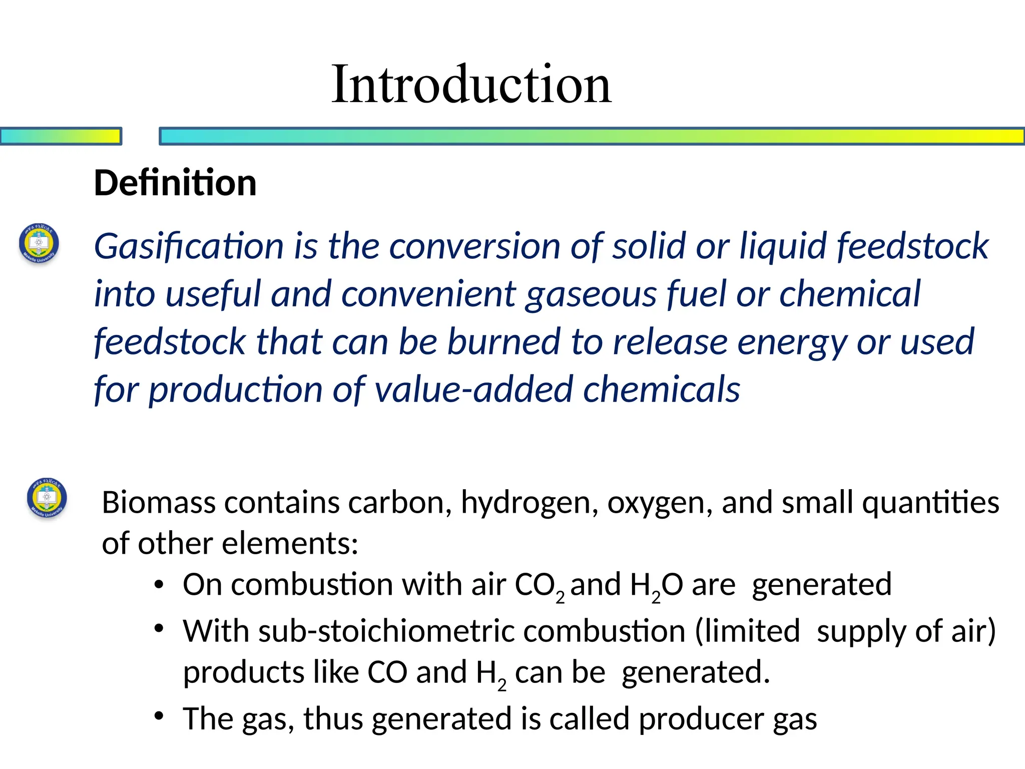
Definition
Gasification is theconversion of solid or liquid feedstock
into useful and convenient gaseous fuel or chemical
feedstock that can be burned to release energy or used
for production of value-added chemicals
Biomass contains carbon, hydrogen, oxygen, and small quantities
of other elements:
• On combustion with air CO2 and H2O are generated
• With sub-stoichiometric combustion (limited supply of air)
products like CO and H2 can be generated.
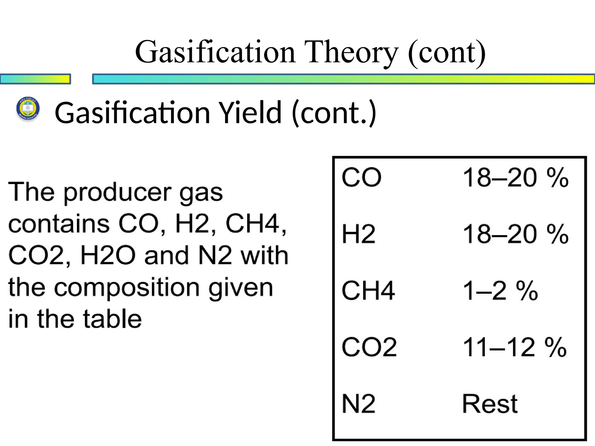
• The gas, thus generated is called producer gas
6.
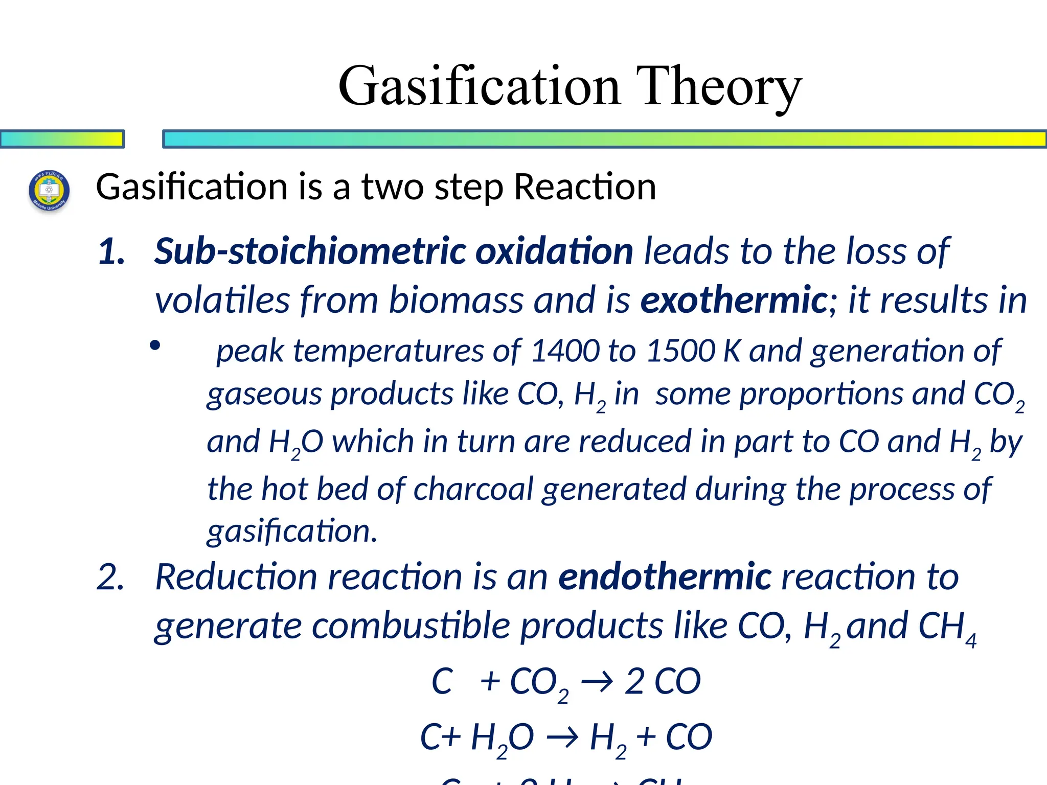
Gasification Theory
Gasification isa two step Reaction
1. Sub-stoichiometric oxidation leads to the loss of
volatiles from biomass and is exothermic; it results in
• peak temperatures of 1400 to 1500 K and generation of
gaseous products like CO, H2 in some proportions and CO2
and H2O which in turn are reduced in part to CO and H2 by
the hot bed of charcoal generated during the process of
gasification.
2. Reduction reaction is an endothermic reaction to
generate combustible products like CO, H2 and CH4
C + CO2 → 2 CO
C+ H2O → H2 + CO
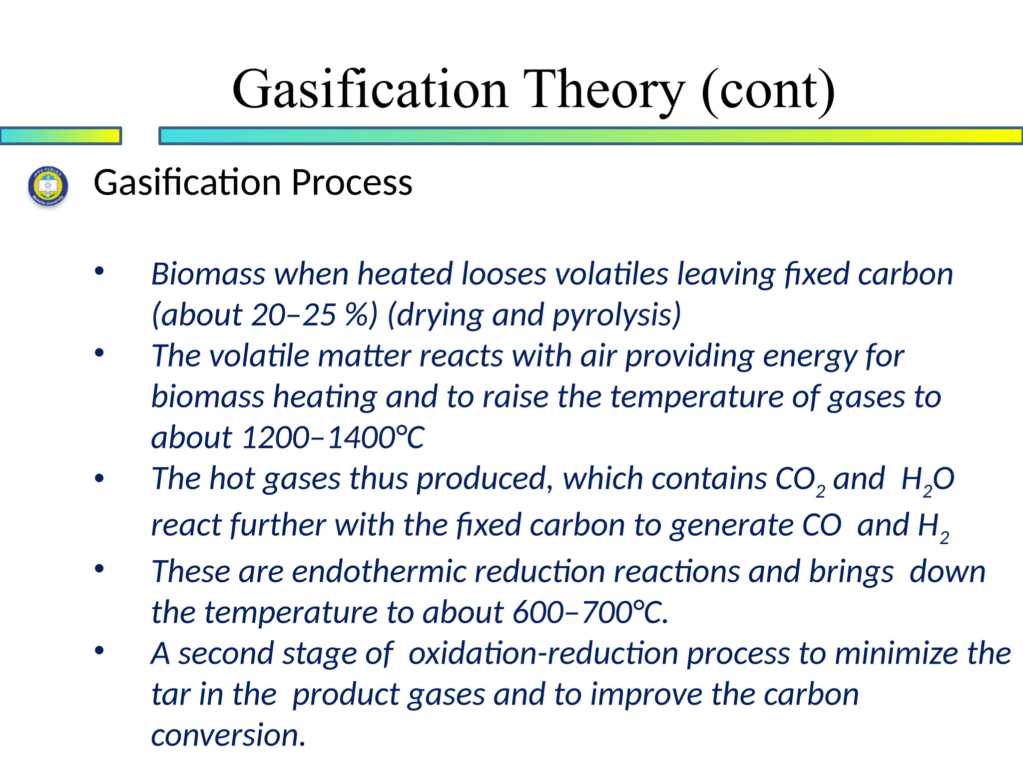
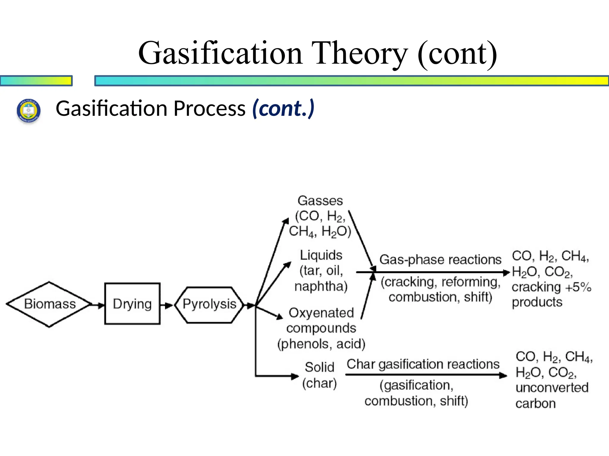
Gasification Process
• Biomasswhen heated looses volatiles leaving fixed carbon
(about 20–25 %) (drying and pyrolysis)
• The volatile matter reacts with air providing energy for
biomass heating and to raise the temperature of gases to
about 1200–1400°C
• The hot gases thus produced, which contains CO2 and H2O
react further with the fixed carbon to generate CO and H2
• These are endothermic reduction reactions and brings down
the temperature to about 600–700°C.
• A second stage of oxidation-reduction process to minimize the
tar in the product gases and to improve the carbon
conversion.
Gasification Theory (cont)
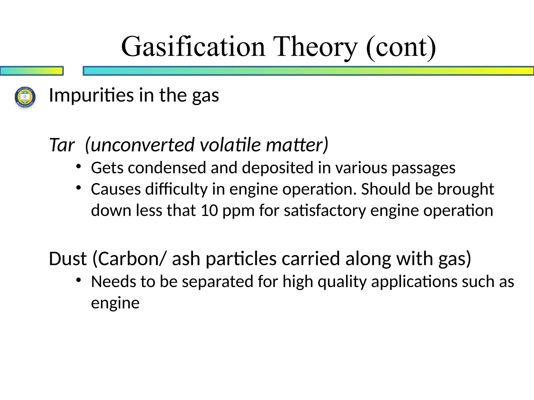
Impurities in thegas
Tar (unconverted volatile matter)
• Gets condensed and deposited in various passages
• Causes difficulty in engine operation. Should be brought
down less that 10 ppm for satisfactory engine operation
Dust (Carbon/ ash particles carried along with gas)
• Needs to be separated for high quality applications such as
engine
Gasification Theory (cont)
13.
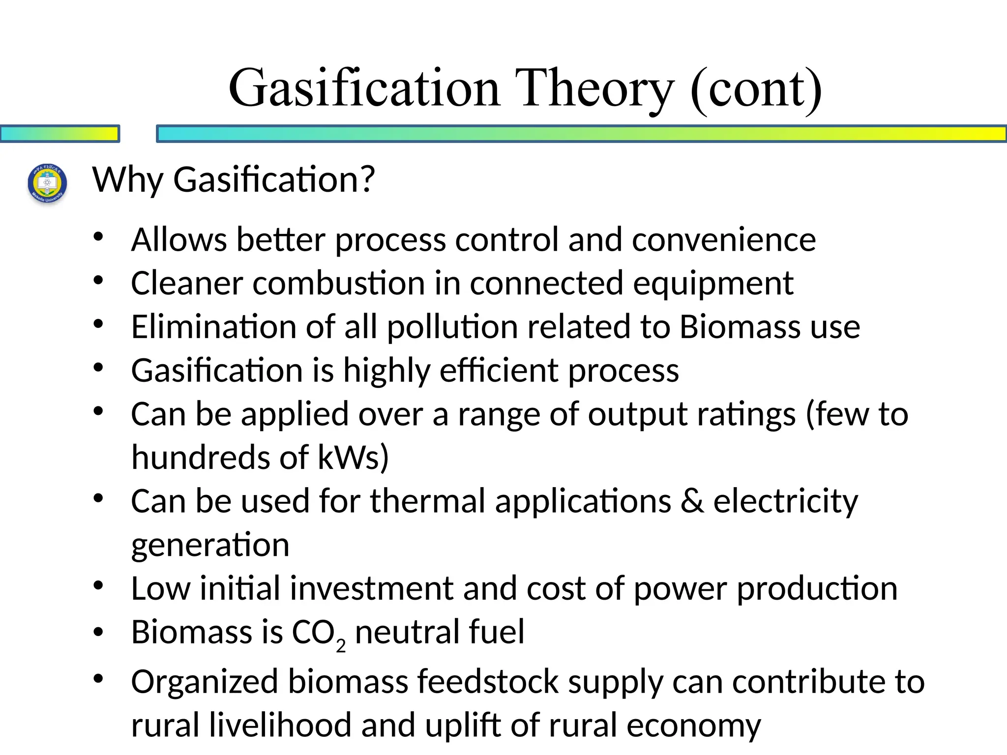
Why Gasification?
• Allowsbetter process control and convenience
• Cleaner combustion in connected equipment
• Elimination of all pollution related to Biomass use
• Gasification is highly efficient process
• Can be applied over a range of output ratings (few to
hundreds of kWs)
• Can be used for thermal applications & electricity
generation
• Low initial investment and cost of power production
• Biomass is CO2 neutral fuel
• Organized biomass feedstock supply can contribute to
rural livelihood and uplift of rural economy
Gasification Theory (cont)
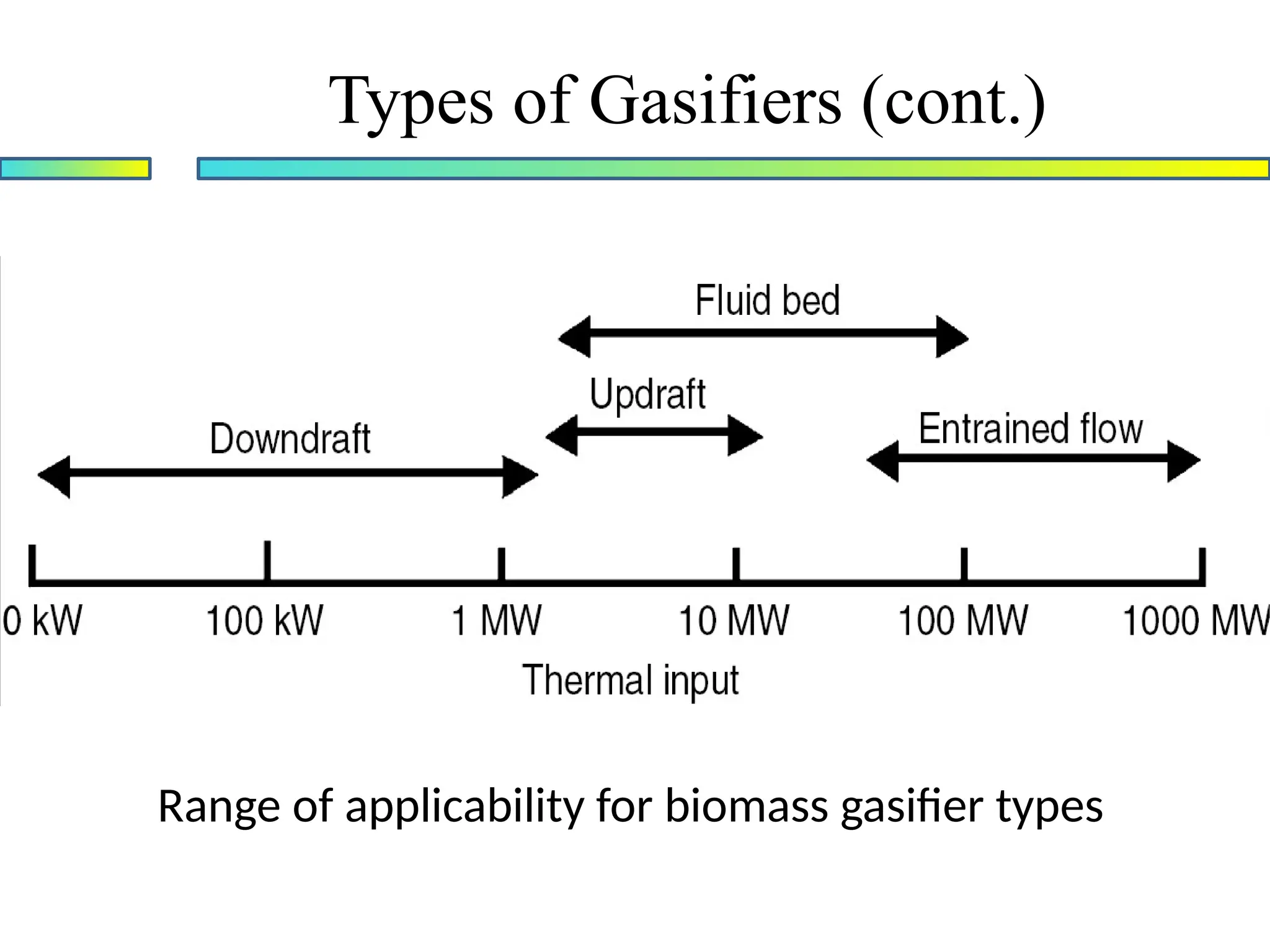
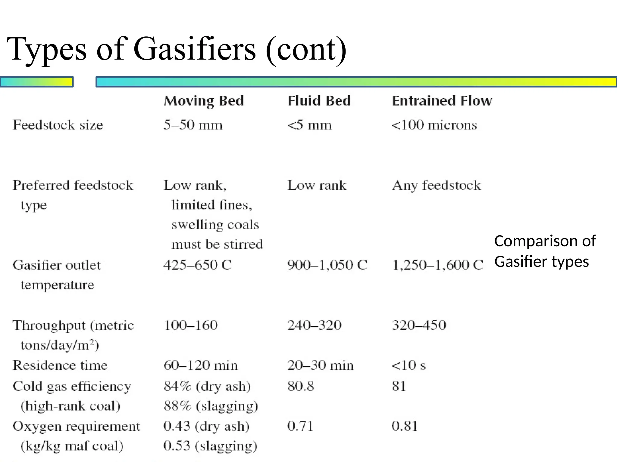
Types of Gasifiers(cont.)
Range of applicability for biomass gasifier types
16.
Types of Gasifiers(cont)
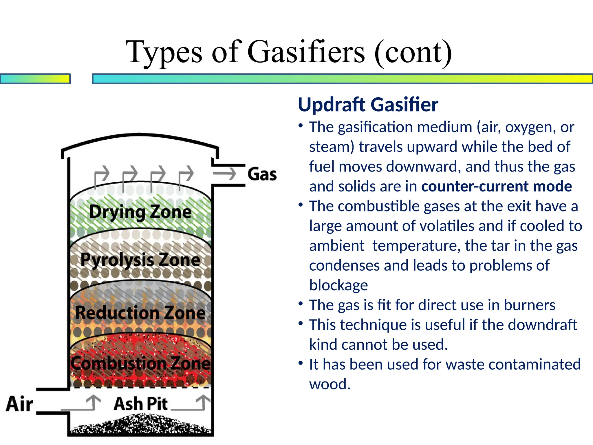
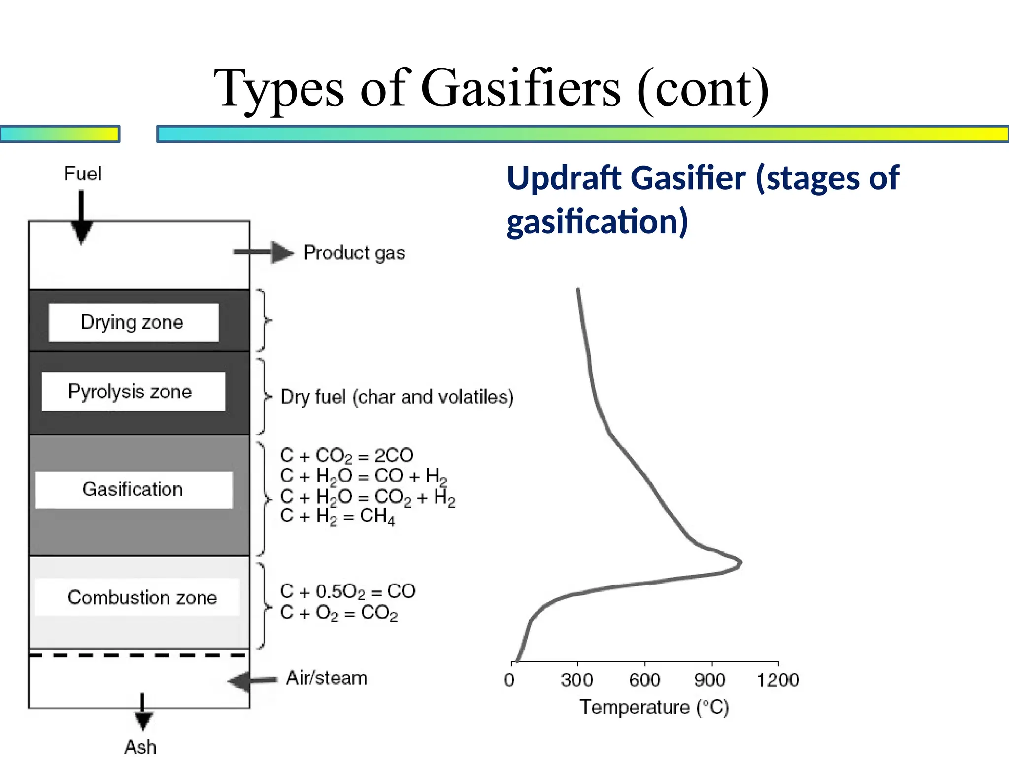
Updraft Gasifier
• The gasification medium (air, oxygen, or
steam) travels upward while the bed of
fuel moves downward, and thus the gas
and solids are in counter-current mode
• The combustible gases at the exit have a
large amount of volatiles and if cooled to
ambient temperature, the tar in the gas
condenses and leads to problems of
blockage
• The gas is fit for direct use in burners
• This technique is useful if the downdraft
kind cannot be used.
• It has been used for waste contaminated
wood.
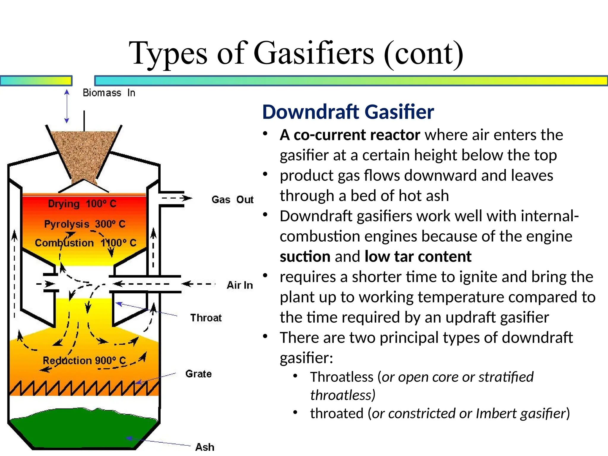
Downdraft Gasifier
• Aco-current reactor where air enters the
gasifier at a certain height below the top
• product gas flows downward and leaves
through a bed of hot ash
• Downdraft gasifiers work well with internal-
combustion engines because of the engine
suction and low tar content
• requires a shorter time to ignite and bring the
plant up to working temperature compared to
the time required by an updraft gasifier
• There are two principal types of downdraft
gasifier:
• Throatless (or open core or stratified
throatless)
• throated (or constricted or Imbert gasifier)
Types of Gasifiers (cont)
19.
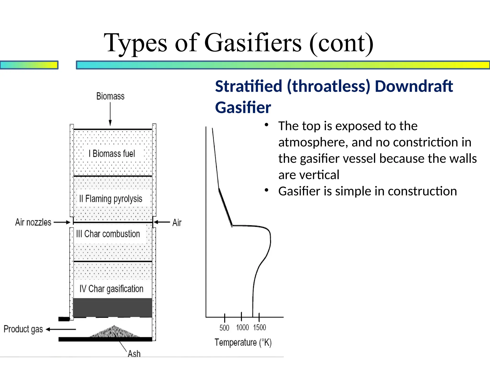
Stratified (throatless) Downdraft
Gasifier
•The top is exposed to the
atmosphere, and no constriction in
the gasifier vessel because the walls
are vertical
• Gasifier is simple in construction
Types of Gasifiers (cont)
20.
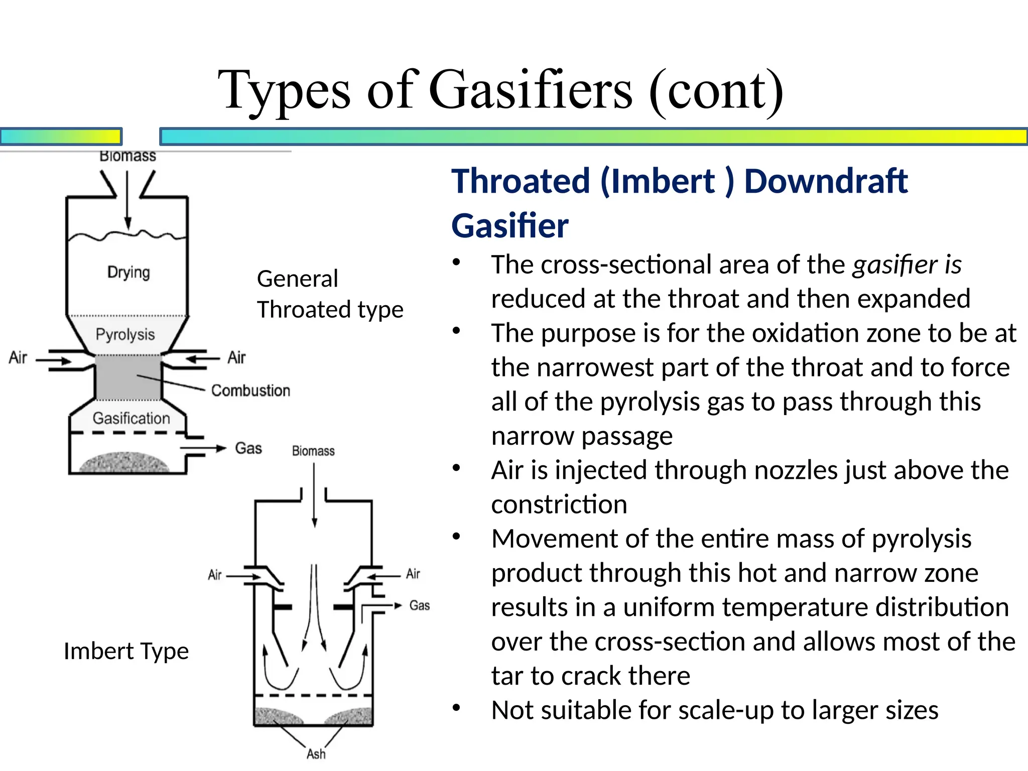
Throated (Imbert )Downdraft
Gasifier
• The cross-sectional area of the gasifier is
reduced at the throat and then expanded
• The purpose is for the oxidation zone to be at
the narrowest part of the throat and to force
all of the pyrolysis gas to pass through this
narrow passage
• Air is injected through nozzles just above the
constriction
• Movement of the entire mass of pyrolysis
product through this hot and narrow zone
results in a uniform temperature distribution
over the cross-section and allows most of the
tar to crack there
• Not suitable for scale-up to larger sizes
General
Throated type
Imbert Type
Types of Gasifiers (cont)
21.
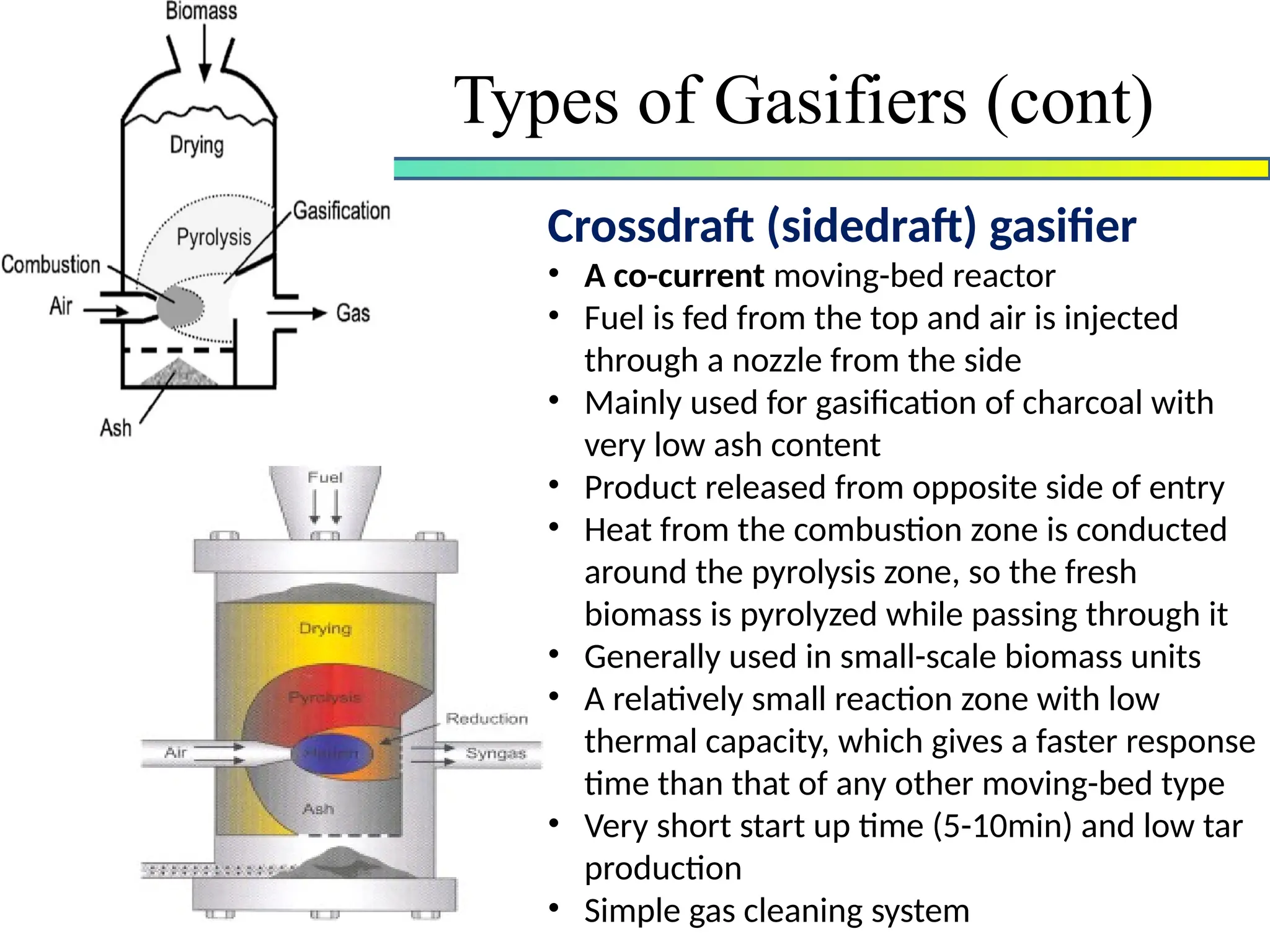
Crossdraft (sidedraft) gasifier
•A co-current moving-bed reactor
• Fuel is fed from the top and air is injected
through a nozzle from the side
• Mainly used for gasification of charcoal with
very low ash content
• Product released from opposite side of entry
• Heat from the combustion zone is conducted
around the pyrolysis zone, so the fresh
biomass is pyrolyzed while passing through it
• Generally used in small-scale biomass units
• A relatively small reaction zone with low
thermal capacity, which gives a faster response
time than that of any other moving-bed type
• Very short start up time (5-10min) and low tar
production
• Simple gas cleaning system
Types of Gasifiers (cont)
22.
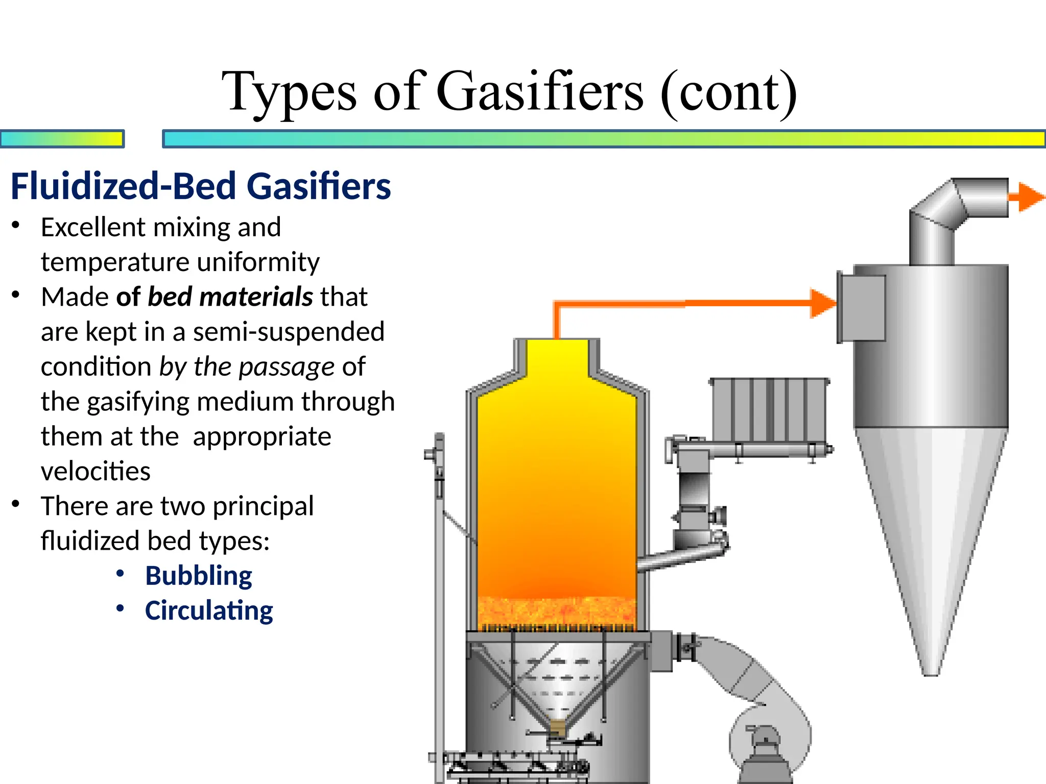
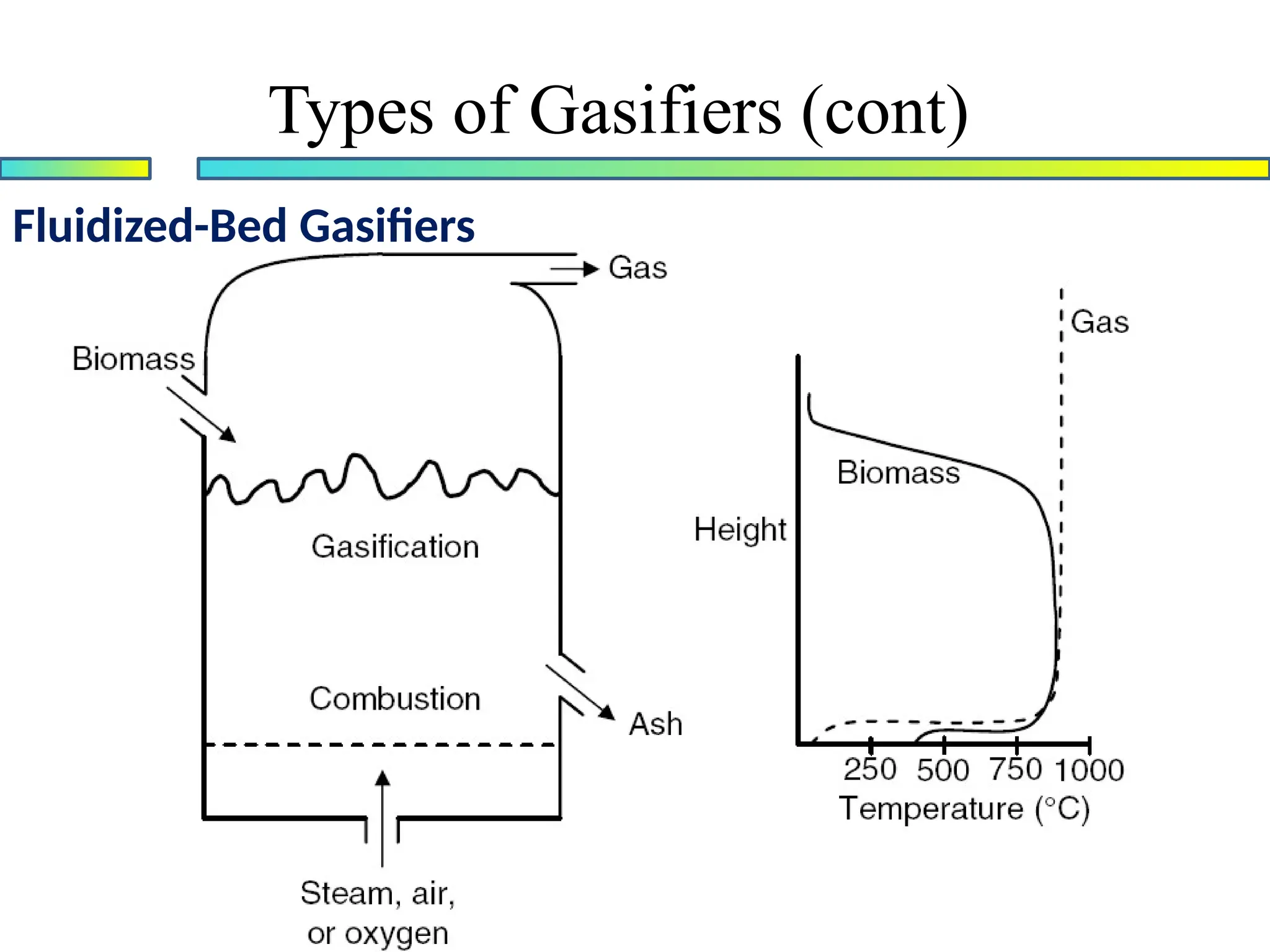
Fluidized-Bed Gasifiers
• Excellentmixing and
temperature uniformity
• Made of bed materials that
are kept in a semi-suspended
condition by the passage of
the gasifying medium through
them at the appropriate
velocities
• There are two principal
fluidized bed types:
• Bubbling
• Circulating
Types of Gasifiers (cont)
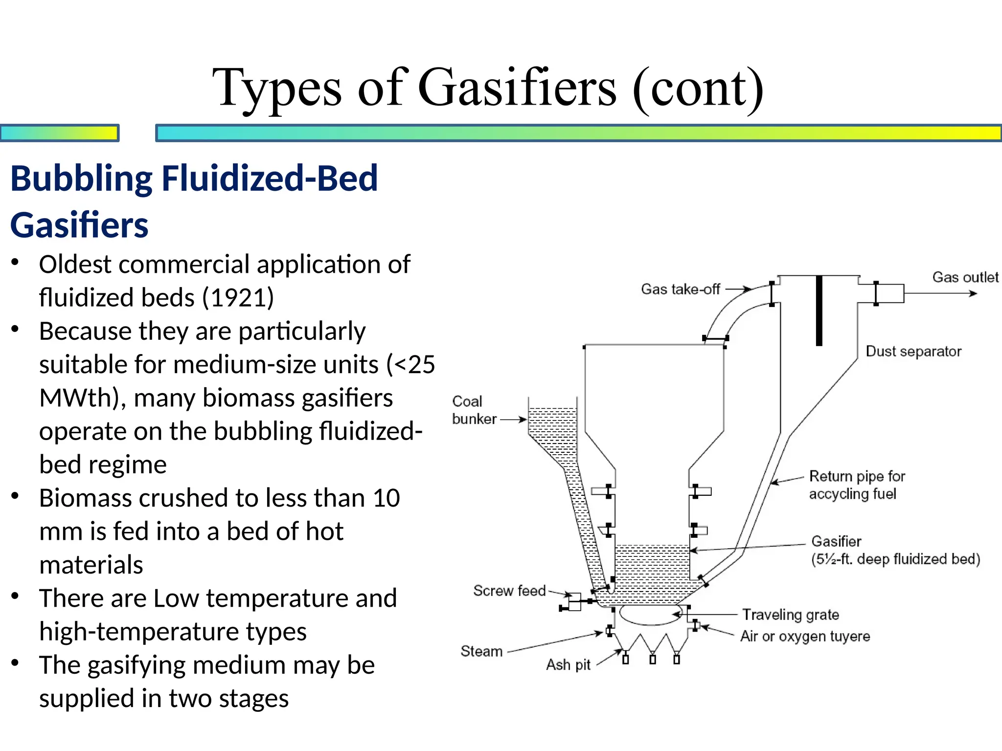
Bubbling Fluidized-Bed
Gasifiers
• Oldestcommercial application of
fluidized beds (1921)
• Because they are particularly
suitable for medium-size units (<25
MWth), many biomass gasifiers
operate on the bubbling fluidized-
bed regime
• Biomass crushed to less than 10
mm is fed into a bed of hot
materials
• There are Low temperature and
high-temperature types
• The gasifying medium may be
supplied in two stages
Types of Gasifiers (cont)
25.
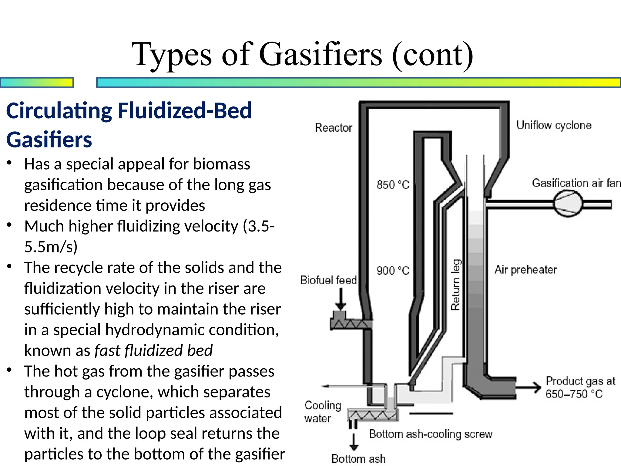
Circulating Fluidized-Bed
Gasifiers
• Hasa special appeal for biomass
gasification because of the long gas
residence time it provides
• Much higher fluidizing velocity (3.5-
5.5m/s)
• The recycle rate of the solids and the
fluidization velocity in the riser are
sufficiently high to maintain the riser
in a special hydrodynamic condition,
known as fast fluidized bed
• The hot gas from the gasifier passes
through a cyclone, which separates
most of the solid particles associated
with it, and the loop seal returns the
particles to the bottom of the gasifier
Types of Gasifiers (cont)
26.
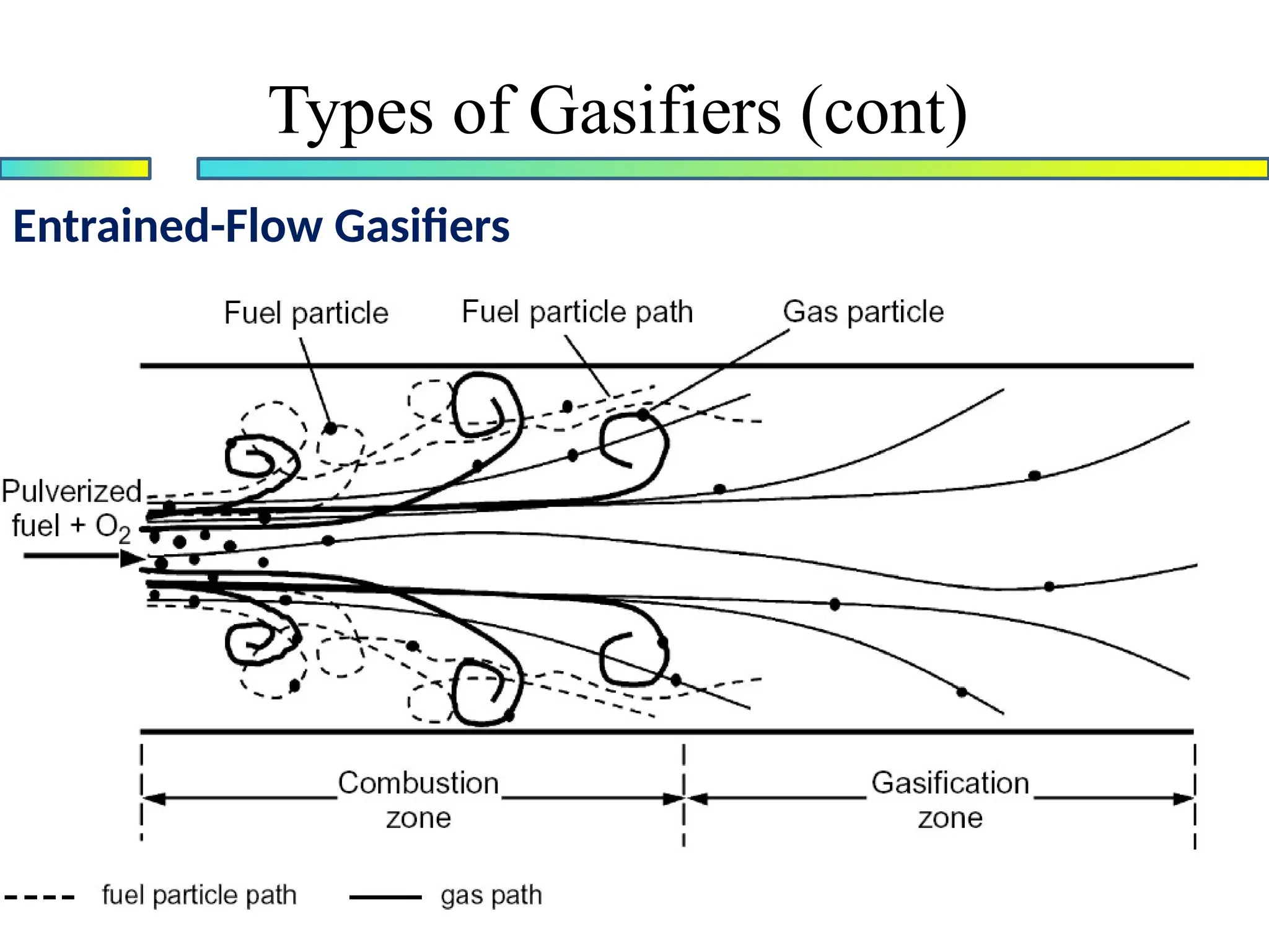
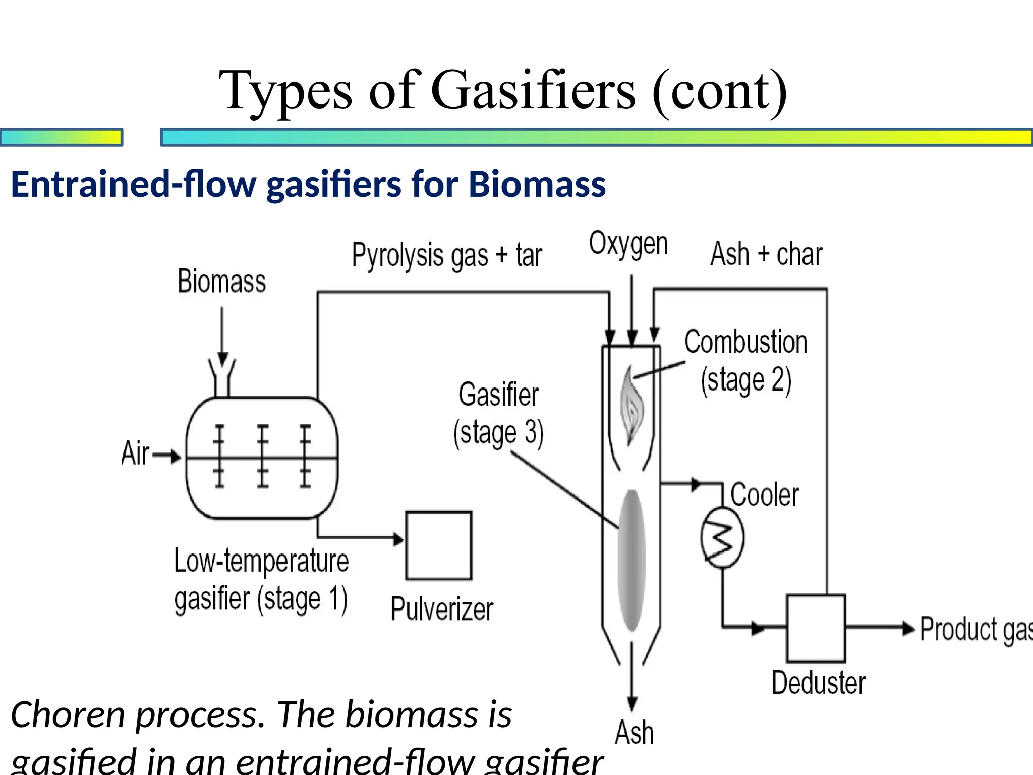
Entrained-Flow Gasifiers
• Entrainedflow is the most successful and widely used
gasifier type for large scale gasification
• Very suitable for a very fine feed but grinding biomass to
a very fine size is difficult
• Entrained-flow reactors are not preferred for biomass
Gasification
• Product contains very low tar and methane content as
the gasification temperature is well above 1000o
C
• Carbon conversion rate may reach 100% with a proper
design of gasifier
• Two Types:
• Top-fed downflow
• Side-fed upflow
Types of Gasifiers (cont)
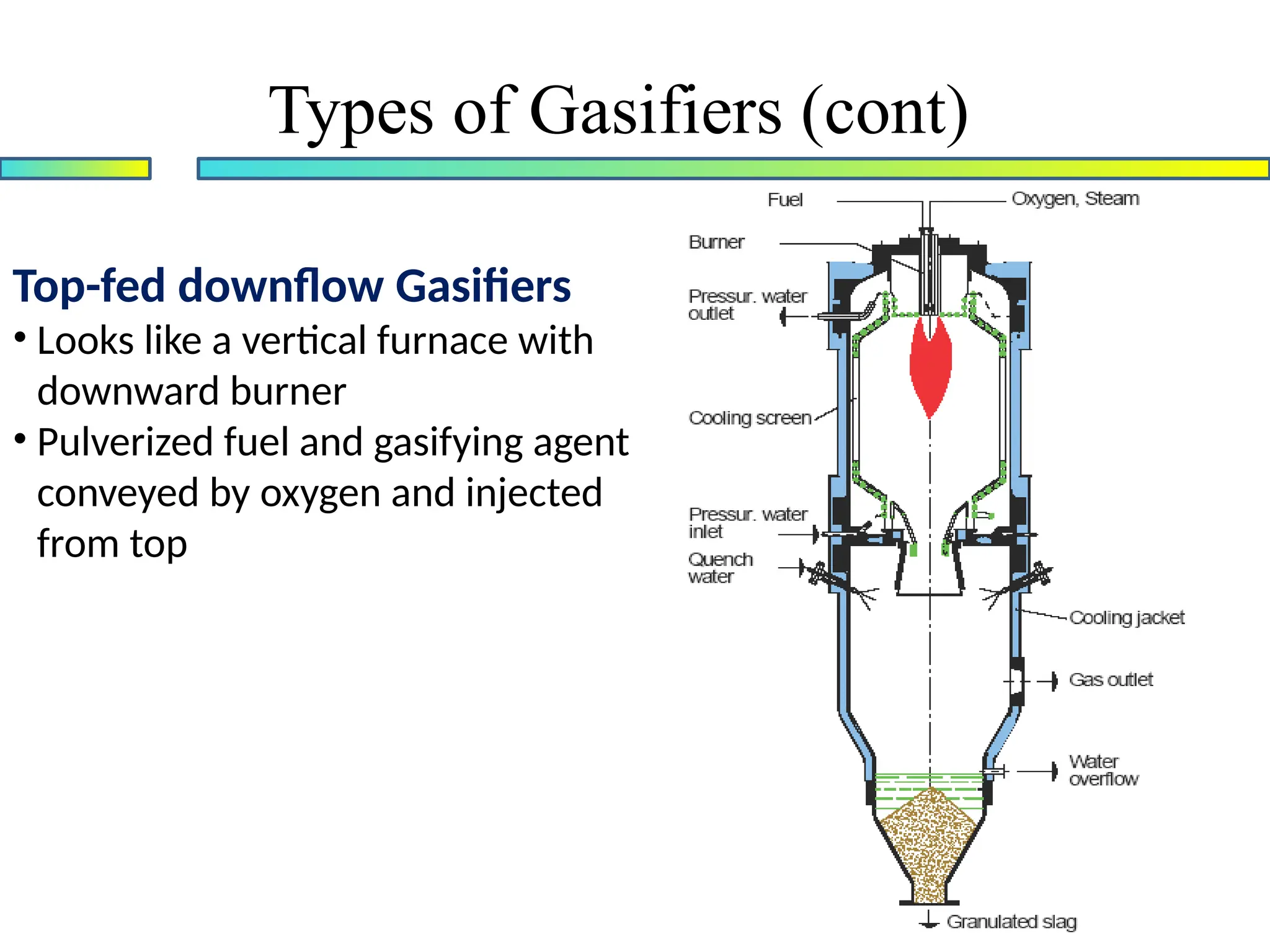
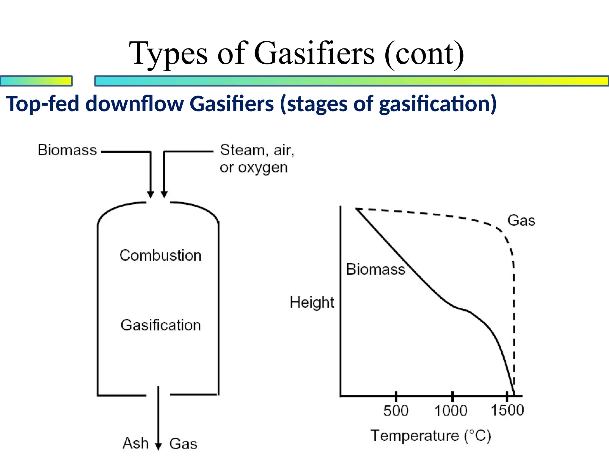
Top-fed downflow Gasifiers
•Looks like a vertical furnace with
downward burner
• Pulverized fuel and gasifying agent
conveyed by oxygen and injected
from top
Types of Gasifiers (cont)
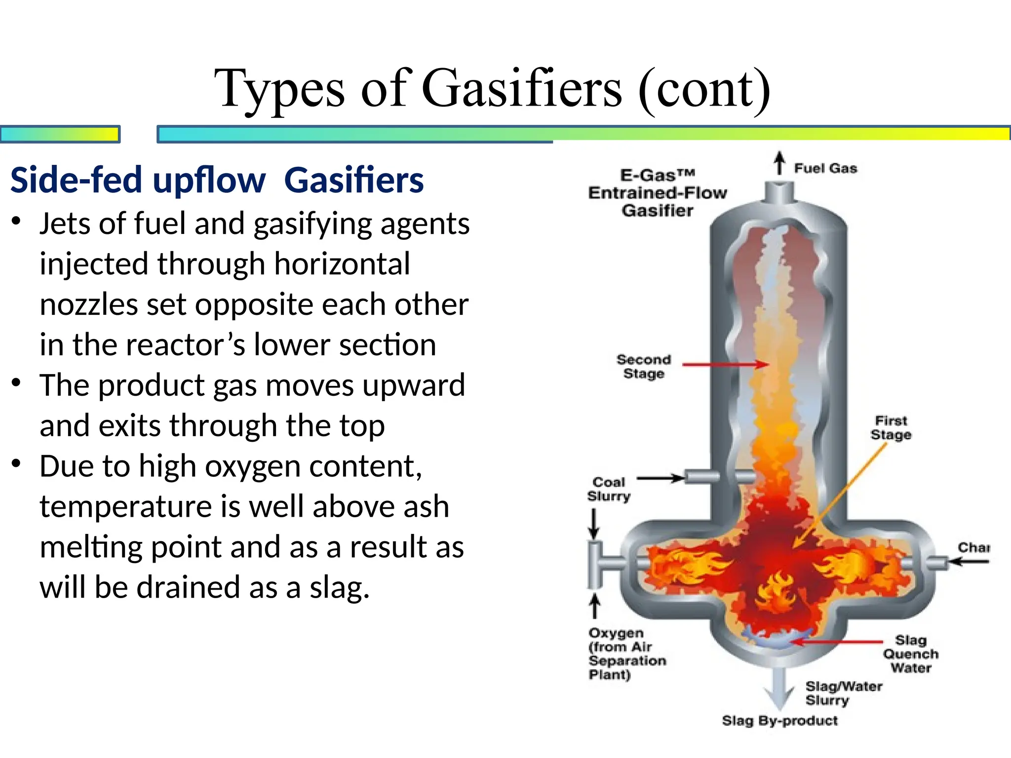
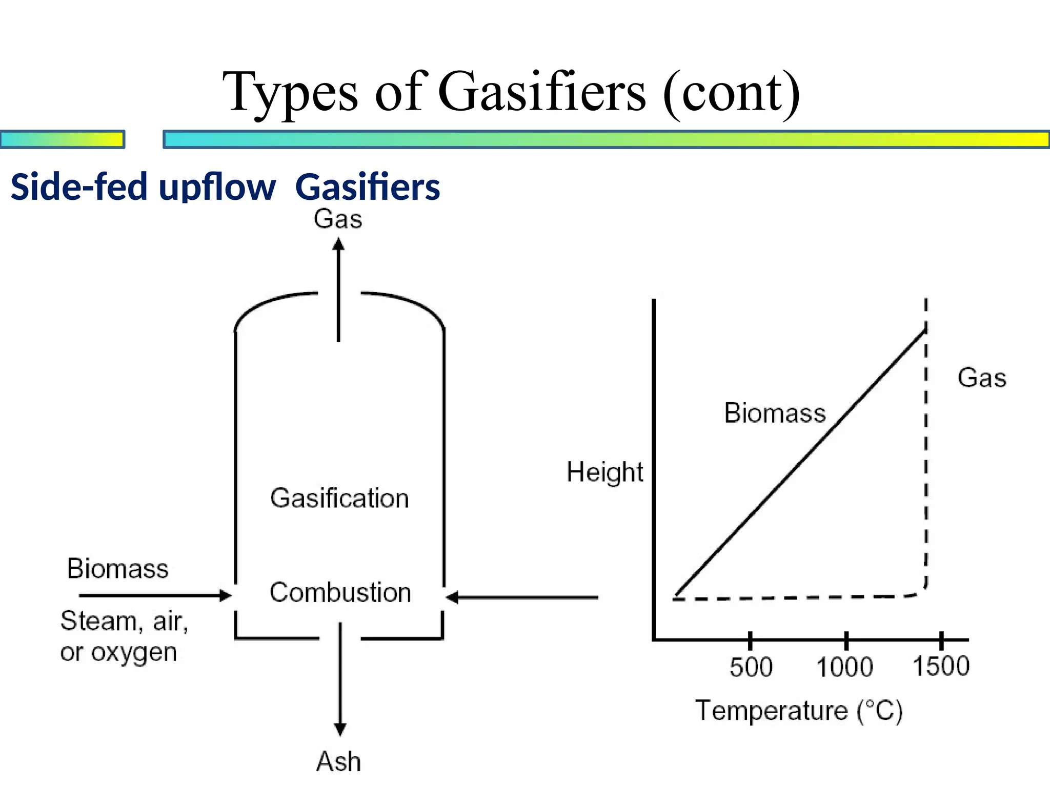
Side-fed upflow Gasifiers
•Jets of fuel and gasifying agents
injected through horizontal
nozzles set opposite each other
in the reactor’s lower section
• The product gas moves upward
and exits through the top
• Due to high oxygen content,
temperature is well above ash
melting point and as a result as
will be drained as a slag.
Types of Gasifiers (cont)
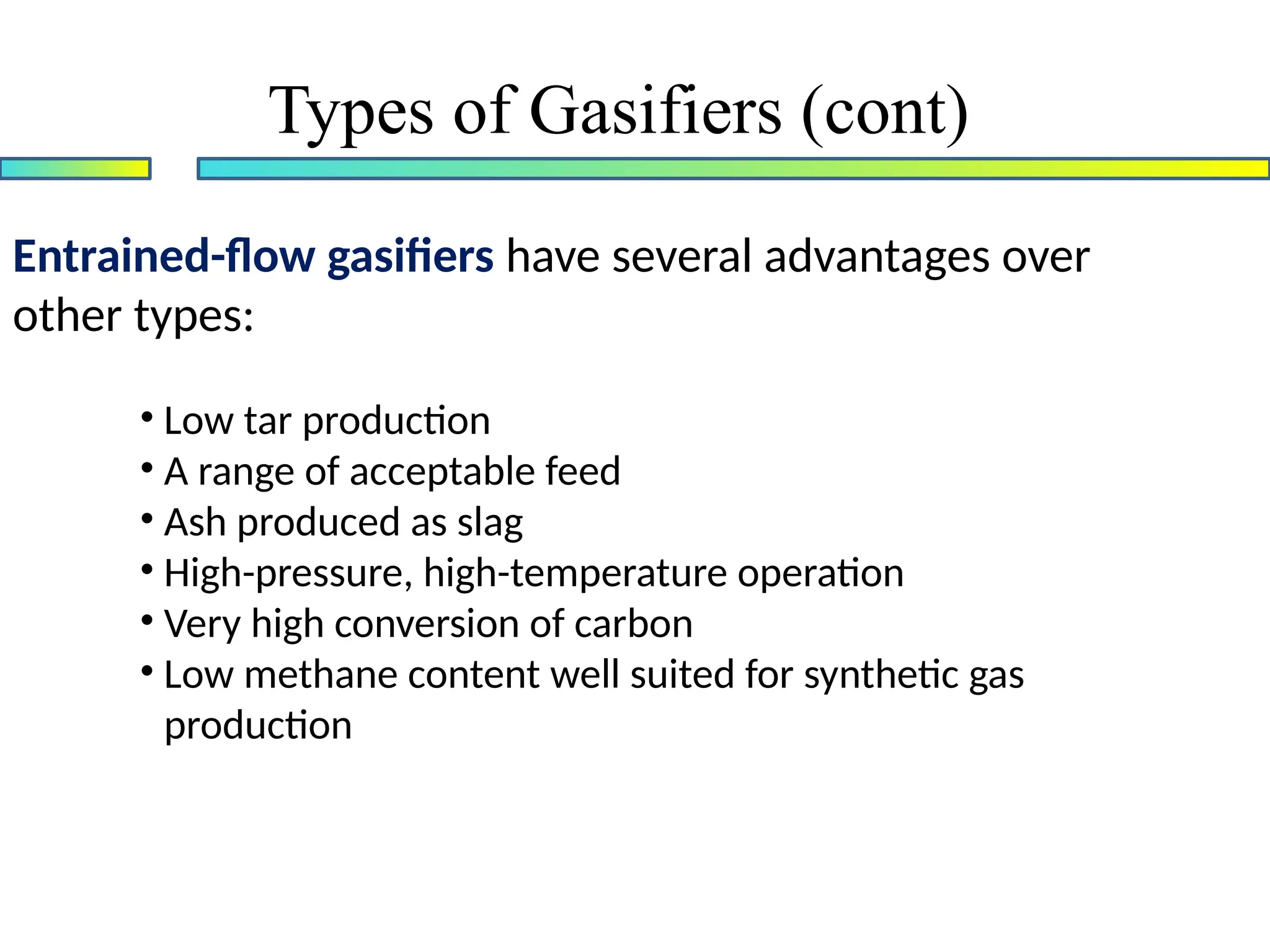
Entrained-flow gasifiers haveseveral advantages over
other types:
• Low tar production
• A range of acceptable feed
• Ash produced as slag
• High-pressure, high-temperature operation
• Very high conversion of carbon
• Low methane content well suited for synthetic gas
production
Types of Gasifiers (cont)
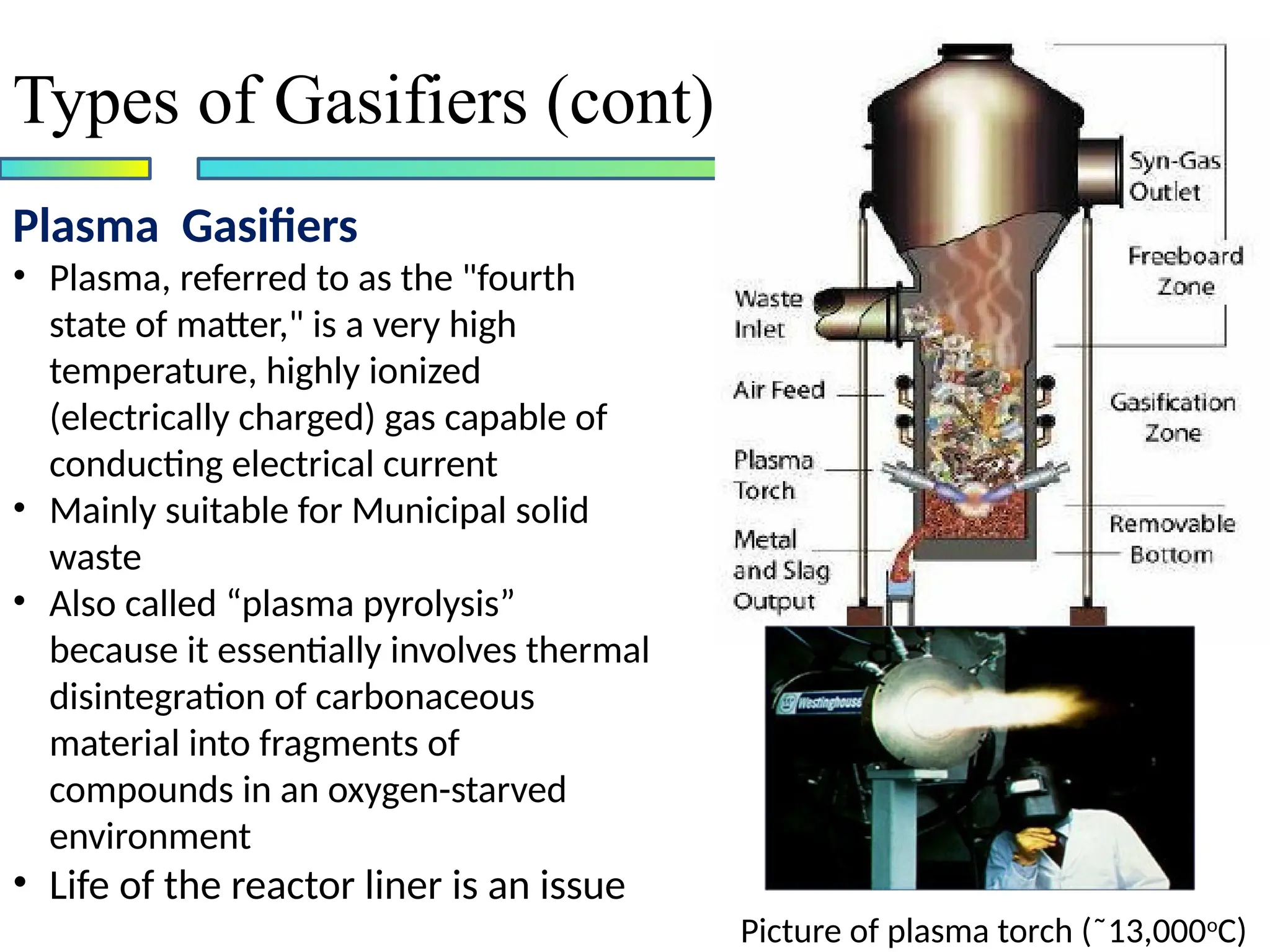
Plasma Gasifiers
• Plasma,referred to as the "fourth
state of matter," is a very high
temperature, highly ionized
(electrically charged) gas capable of
conducting electrical current
• Mainly suitable for Municipal solid
waste
• Also called “plasma pyrolysis”
because it essentially involves thermal
disintegration of carbonaceous
material into fragments of
compounds in an oxygen-starved
environment
• Life of the reactor liner is an issue
Types of Gasifiers (cont)
Picture of plasma torch (˜13,000o
C)
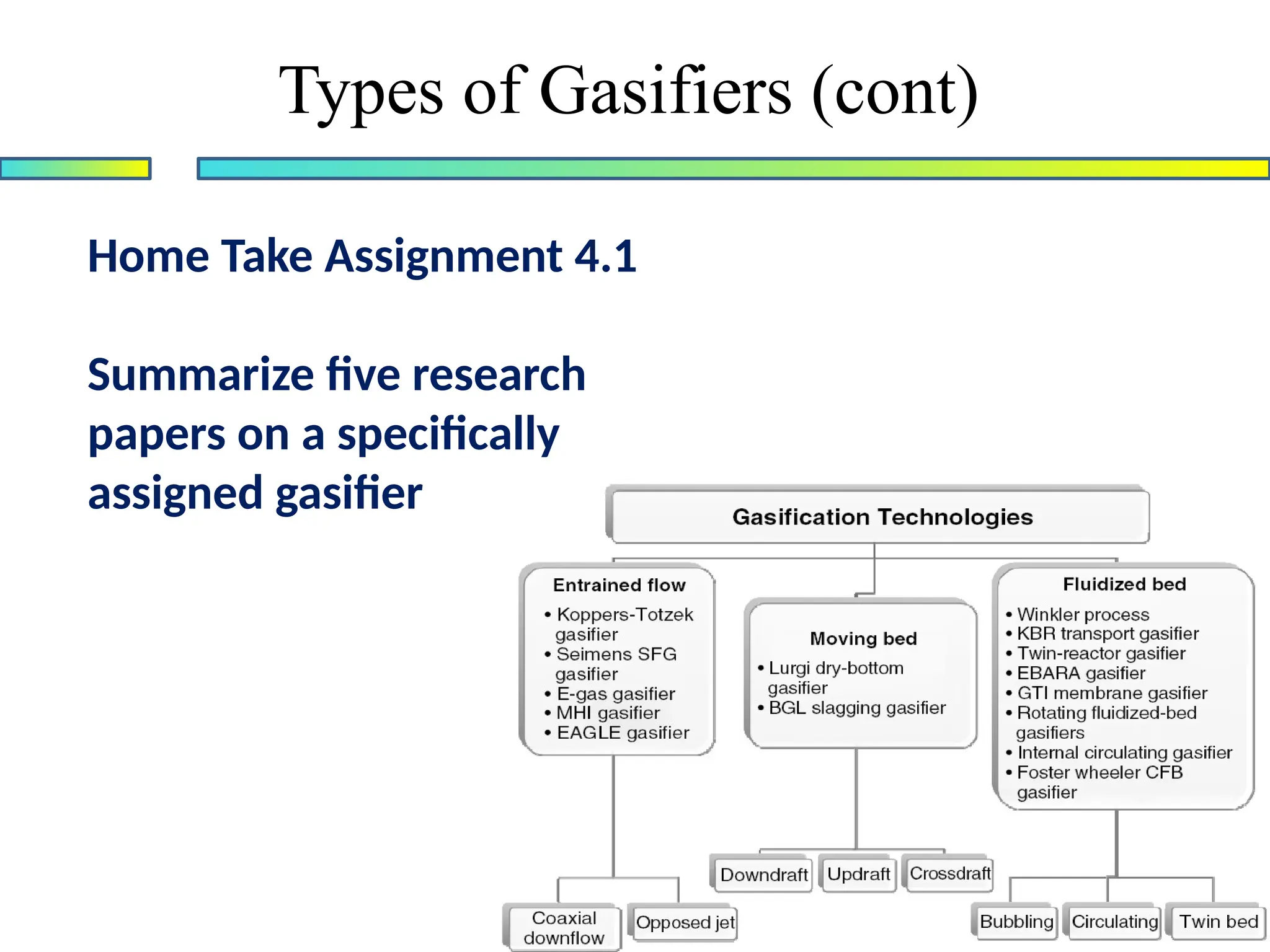
Home Take Assignment4.1
Summarize five research
papers on a specifically
assigned gasifier
Types of Gasifiers (cont)
37.
Self reading
Prabir Basu,“Biomass Gasification and Pyrolysis :
Practical Design and Theory”, Elsevier Inc, 2010
PP 136-148
Kinetics of Gasification
38.
Design of Gasifiers
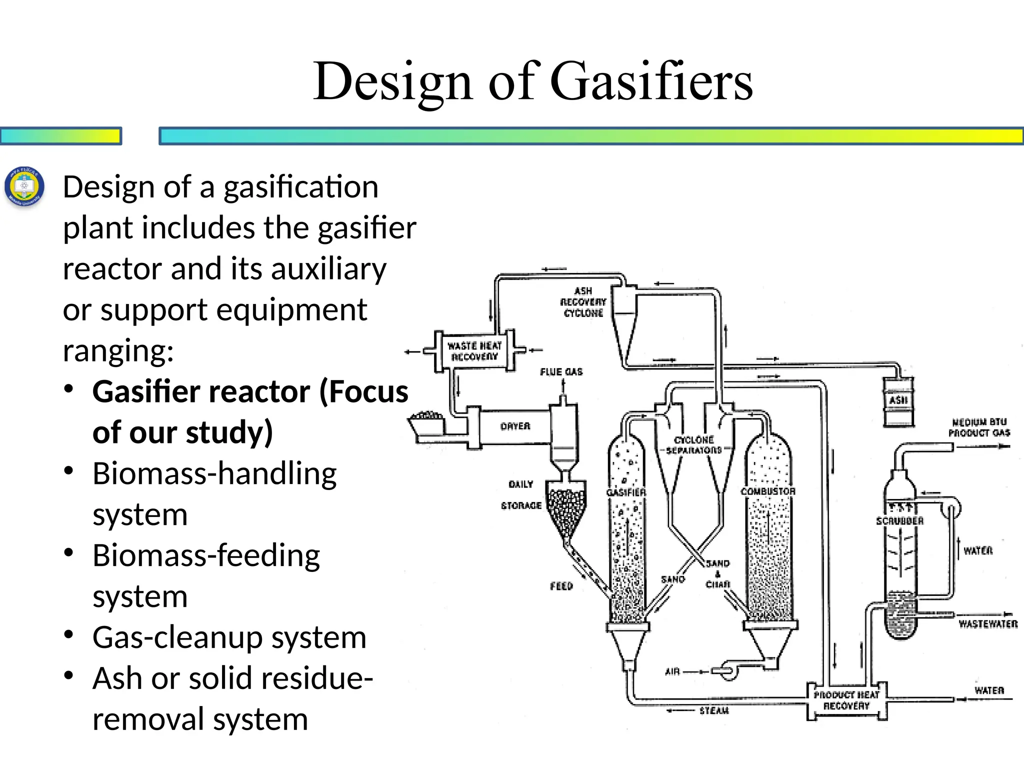
Designof a gasification
plant includes the gasifier
reactor and its auxiliary
or support equipment
ranging:
• Gasifier reactor (Focus
of our study)
• Biomass-handling
system
• Biomass-feeding
system
• Gas-cleanup system
• Ash or solid residue-
removal system
39.
Design of Gasifiers(cont.)
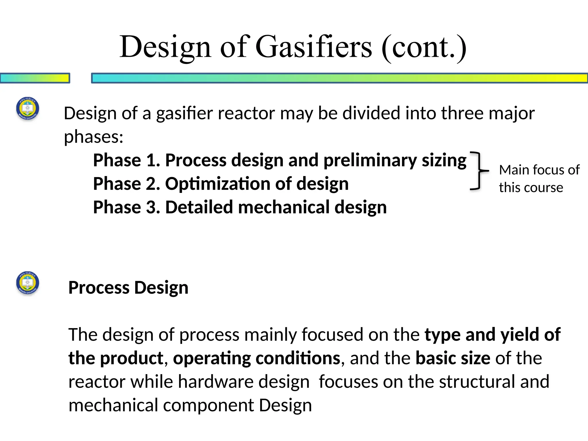
Design of a gasifier reactor may be divided into three major
phases:
Phase 1. Process design and preliminary sizing
Phase 2. Optimization of design
Phase 3. Detailed mechanical design
Main focus of
this course
Process Design
The design of process mainly focused on the type and yield of
the product, operating conditions, and the basic size of the
reactor while hardware design focuses on the structural and
mechanical component Design
40.
At the endof process design, we will be able to
determine:
• Geometry including reactor configuration, cross-section
area, and height
• Operating parameters like reactor temperature; preheat
temperature of the steam, air, or oxygen; and amount
(i.e., steam/biomass ratio) and relative proportion of the
gasifying medium (i.e., steam/oxygen ratio)
• Performance parameters like carbon conversion and cold-
gas efficiency
Design of Gasifiers (cont.)
41.
Design of Gasifiers(cont.)
The parameters required for the process design of gasifier
reactor are:
• Design Specification
• Mass Balance
• Energy Balance
42.
Design of Gasifiers(cont.)
Design Specification (Design Capacity)
The first point in the gasifier design is to identify the application and the
size/capacity of the gasifier in term of the product requirement and the
fuel to be gasified., That include
• Specification of the fuel
• Gasification medium
• Product gas
43.
• Specification ofthe fuel
• proximate and ultimate analysis
• operating temperatures
• ash properties
• Gasification medium
• Steam (HV in the range of 10-18MJ/Nm3
)
• Oxygen (HV in the range of 12-28MJ/Nm3
)
• Air (HV in the range of 4-7MJ/Nm3
)
• Product gas
• Desired gas composition
• Desired heating value
• Desired production rate (Nm3
/s or MWth produced)
• Yield of the product gas per unit fuel consumed
• Required power output of the gasifier, Q
Design Specification (cont.)
Design of Gasifiers (cont.)
44.
Mass Balance
Design ofGasifiers (cont.)
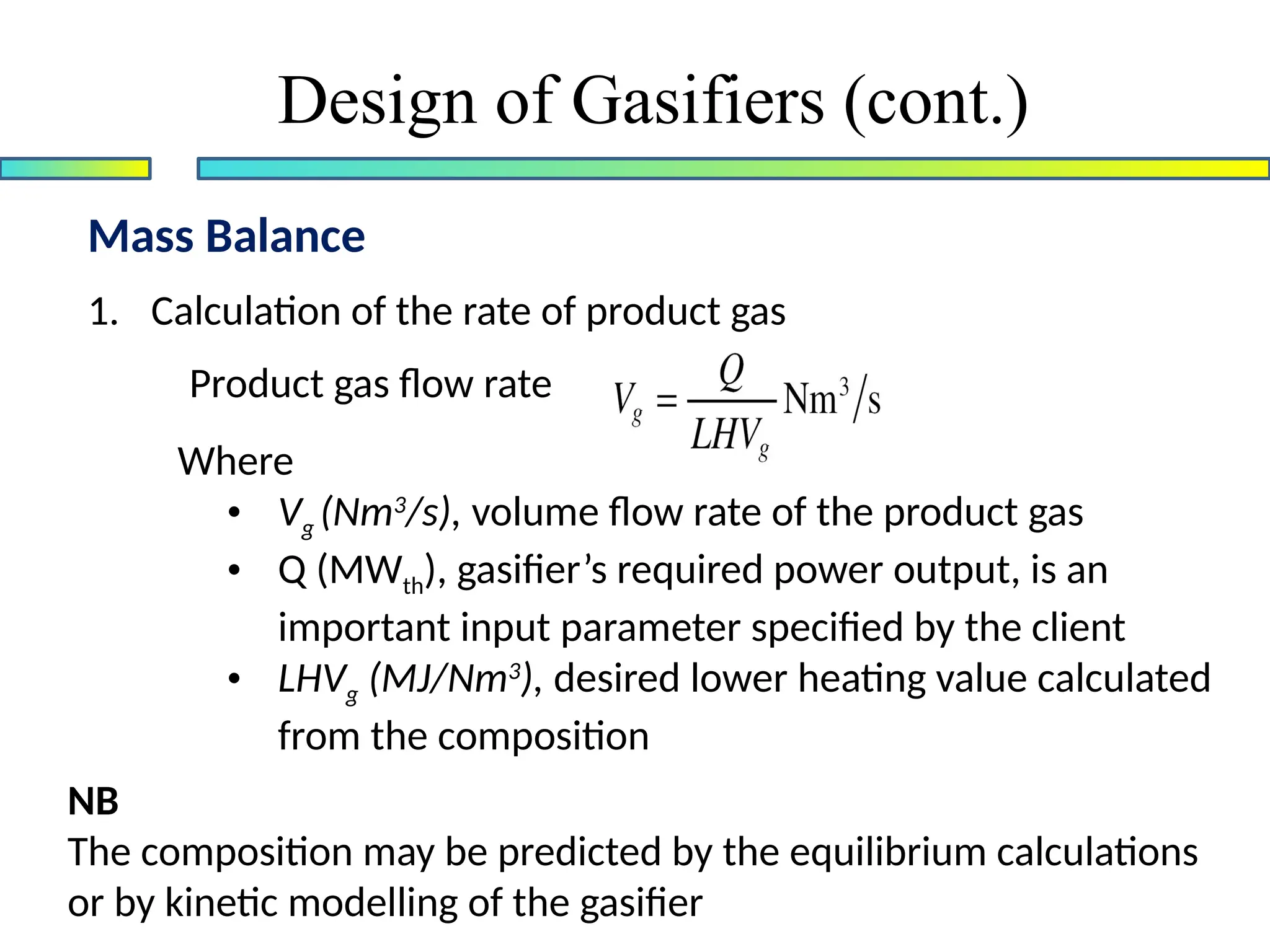
1. Calculation of the rate of product gas
Product gas flow rate
Where
• Vg (Nm3
/s), volume flow rate of the product gas
• Q (MWth), gasifier’s required power output, is an
important input parameter specified by the client
• LHVg (MJ/Nm3
), desired lower heating value calculated
from the composition
NB
The composition may be predicted by the equilibrium calculations
or by kinetic modelling of the gasifier
45.
Mass Balance (cont.)
Designof Gasifiers (cont.)
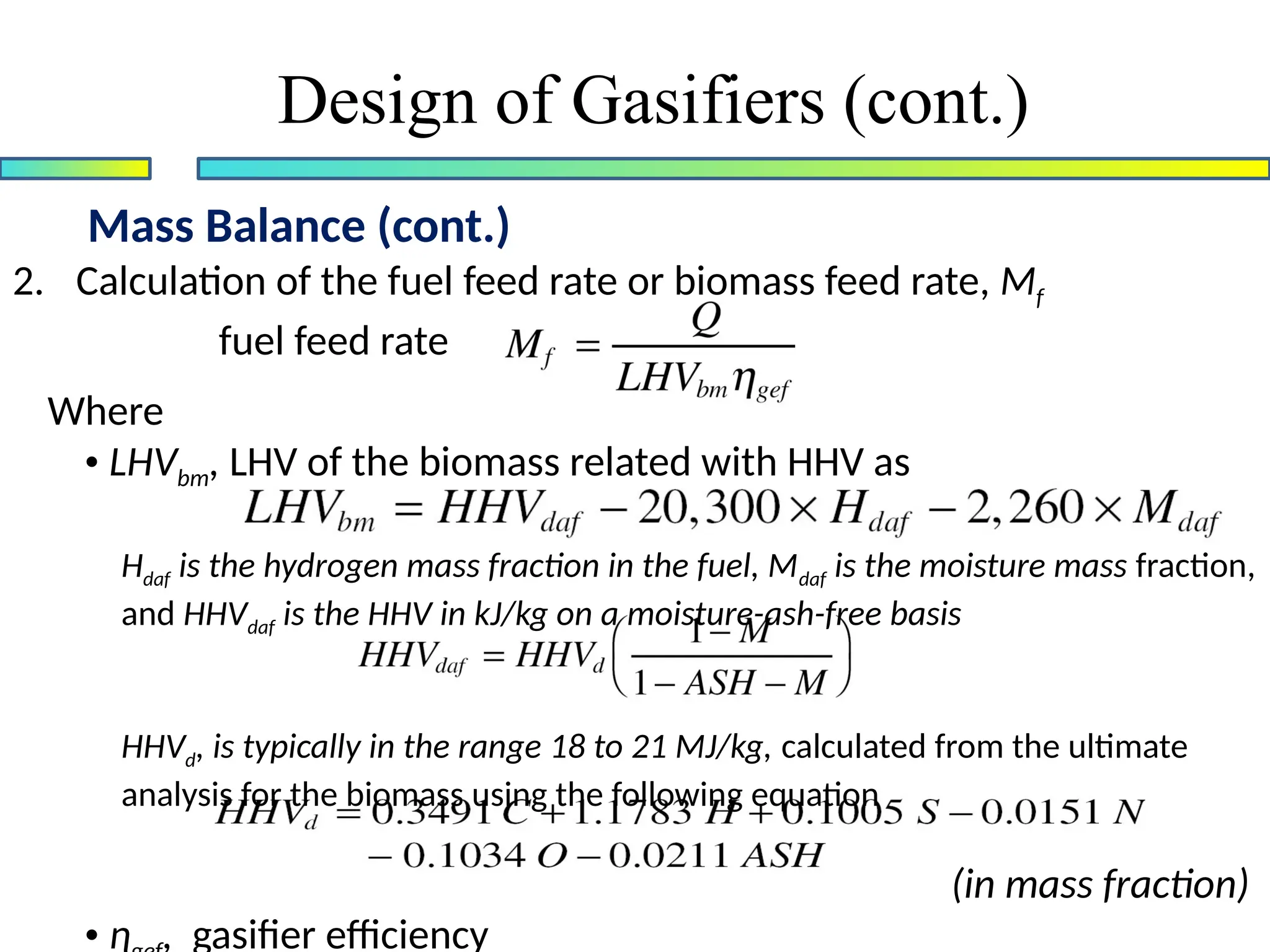
2. Calculation of the fuel feed rate or biomass feed rate, Mf
fuel feed rate
Where
• LHVbm, LHV of the biomass related with HHV as
Hdaf is the hydrogen mass fraction in the fuel, Mdaf is the moisture mass fraction,
and HHVdaf is the HHV in kJ/kg on a moisture-ash-free basis
HHVd, is typically in the range 18 to 21 MJ/kg, calculated from the ultimate
analysis for the biomass using the following equation
(in mass fraction)
• ɳ , gasifier efficiency
46.
Mass Balance (cont.)
Designof Gasifiers (cont.)
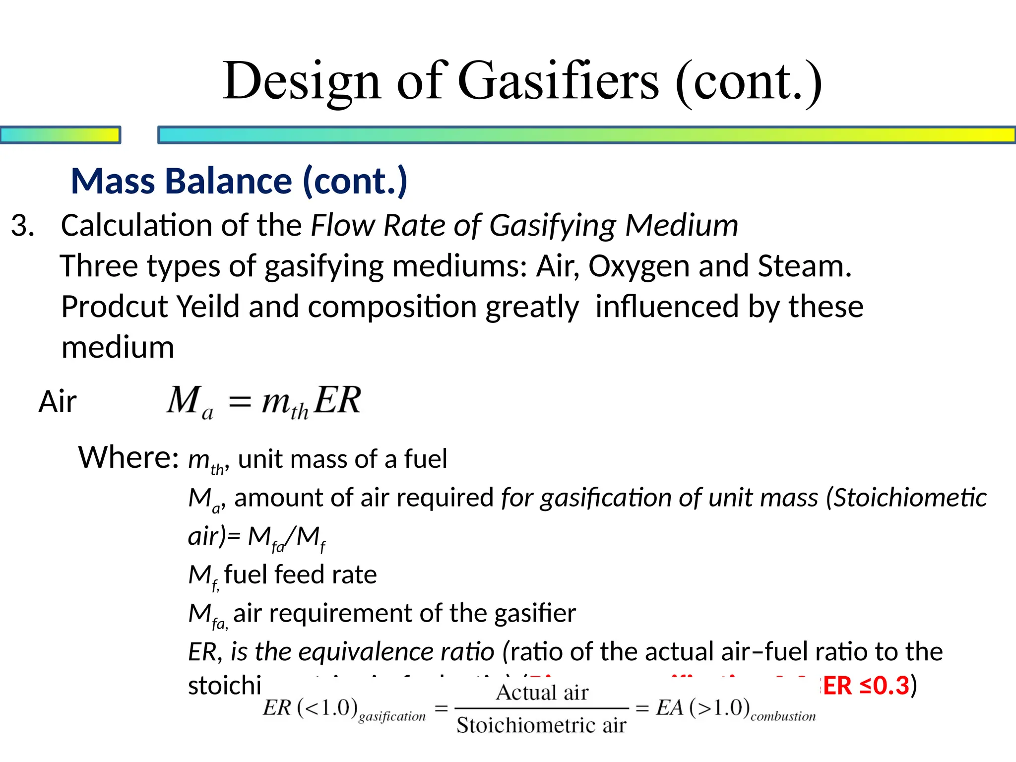
3. Calculation of the Flow Rate of Gasifying Medium
Three types of gasifying mediums: Air, Oxygen and Steam.
Prodcut Yeild and composition greatly influenced by these
medium
Air
Where: mth, unit mass of a fuel
Ma, amount of air required for gasification of unit mass (Stoichiometic
air)= Mfa/Mf
Mf, fuel feed rate
Mfa, air requirement of the gasifier
ER, is the equivalence ratio (ratio of the actual air–fuel ratio to the
stoichiometric air–fuel ratio) (Biomass gasification 0.2≤ER ≤0.3)
47.
Mass Balance (cont.)
Designof Gasifiers (cont.)
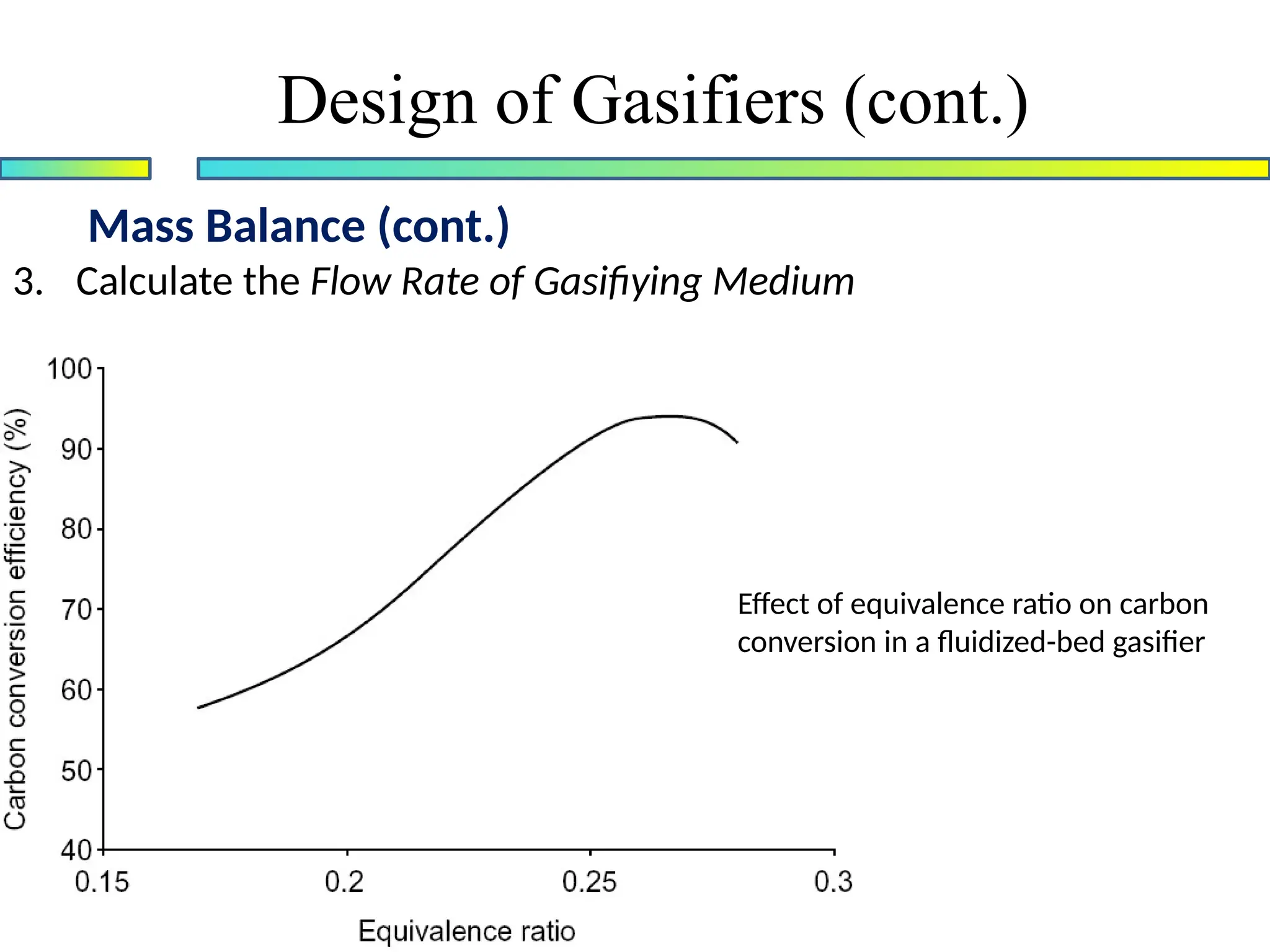
3. Calculate the Flow Rate of Gasifiying Medium
Effect of equivalence ratio on carbon
conversion in a fluidized-bed gasifier
48.
Energy Balance
Design ofGasifiers (cont.)
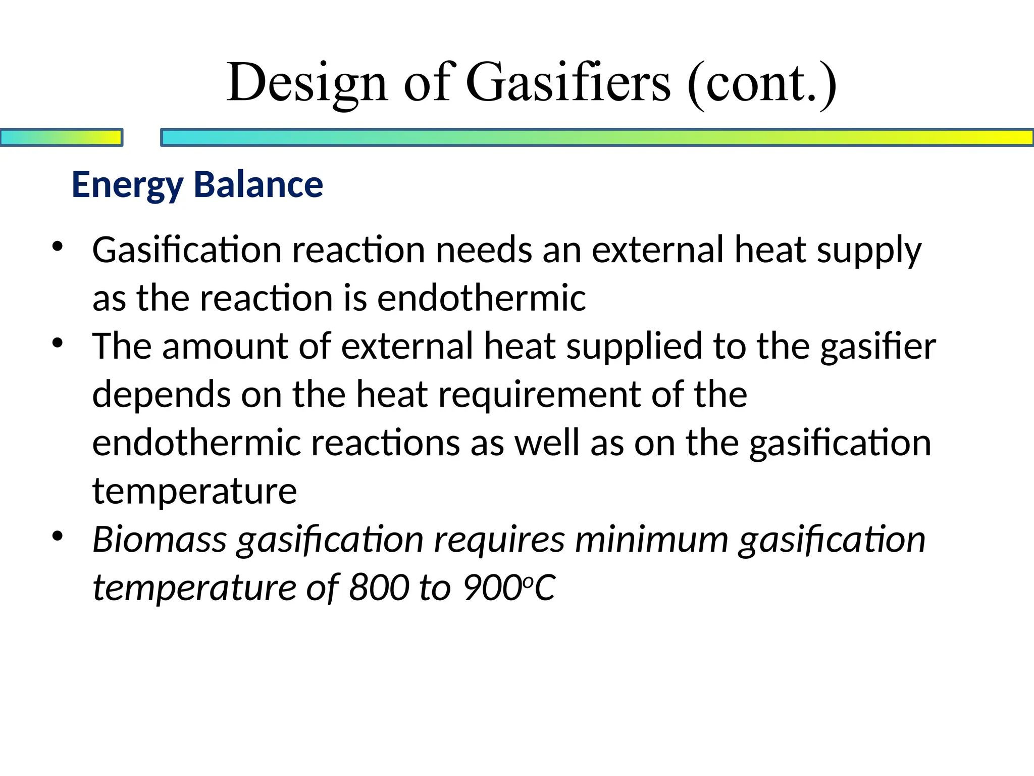
• Gasification reaction needs an external heat supply
as the reaction is endothermic
• The amount of external heat supplied to the gasifier
depends on the heat requirement of the
endothermic reactions as well as on the gasification
temperature
• Biomass gasification requires minimum gasification
temperature of 800 to 900o
C
49.
Energy Balance (cont.)
Designof Gasifiers (cont.)
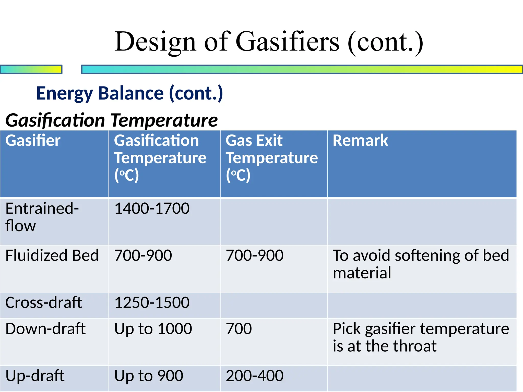
Gasification Temperature
Gasifier Gasification
Temperature
(o
C)
Gas Exit
Temperature
(o
C)
Remark
Entrained-
flow
1400-1700
Fluidized Bed 700-900 700-900 To avoid softening of bed
material
Cross-draft 1250-1500
Down-draft Up to 1000 700 Pick gasifier temperature
is at the throat
Up-draft Up to 900 200-400
50.
Energy Balance (cont.)
Designof Gasifiers (cont.)
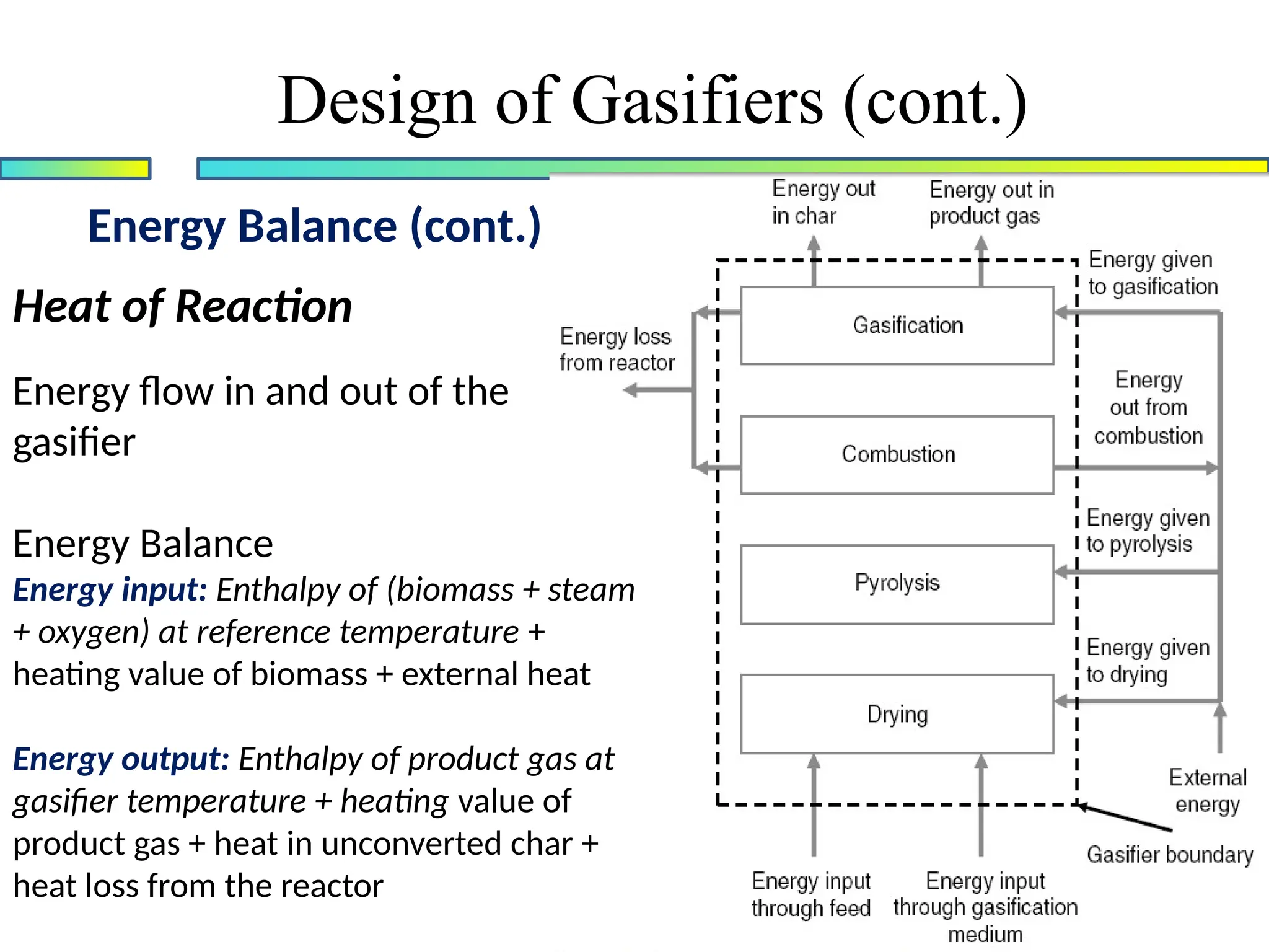
Heat of Reaction
The heat gained or lost in a chemical reaction is called heat of reaction
Heat of reaction = [the sum of all heats of formation of all products] -
[the sum of all heats of formation of all reactants]
To calculate it for gasification, we consider an overall gasification
reaction where 1 mol of biomass (CaHbOc) is gasified in α mols of steam
and β mols of oxygen
The overall equation is
Q is the net heat supplied to the reactor
51.
Energy Balance (cont.)
Designof Gasifiers (cont.)
Heat of Reaction
Energy flow in and out of the
gasifier
Energy Balance
Energy input: Enthalpy of (biomass + steam
+ oxygen) at reference temperature +
heating value of biomass + external heat
Energy output: Enthalpy of product gas at
gasifier temperature + heating value of
product gas + heat in unconverted char +
heat loss from the reactor
52.
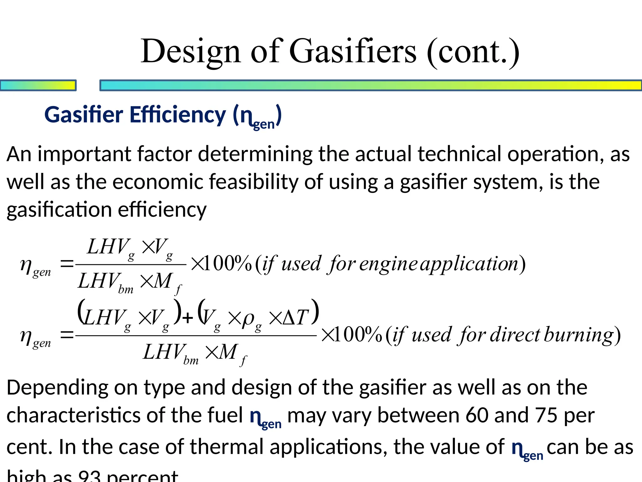
Gasifier Efficiency (ɳgen)
Designof Gasifiers (cont.)
An important factor determining the actual technical operation, as
well as the economic feasibility of using a gasifier system, is the
gasification efficiency
Depending on type and design of the gasifier as well as on the
characteristics of the fuel ɳgen may vary between 60 and 75 per
cent. In the case of thermal applications, the value of ɳgen can be as
)
(
%
100
)
(
%
100
burning
direct
for
used
if
M
LHV
T
V
V
LHV
n
applicatio
engine
for
used
if
M
LHV
V
LHV
f
bm
g
g
g
g
gen
f
bm
g
g
gen
53.
Design of Gasifiers(cont.)
Self Reading:
Gasifier sizing and design of gasifiers in general:
Prabir Basu, “Biomass Gasification and Pyrolysis : Practical
Design and Theory”, Elsevier Inc, 2010
PP 205-217
T.B. Reed and A. Das, “Handbook of Biomass downdraft
gasifier engine systems”, Solar Technical Information Program,
Solar energy Research Institute, Golden, Colorado, 1988
PP 30-50
Wood gas as a fuel engine, FAO Foresty Paper 72, 1986 pp 16-
54.
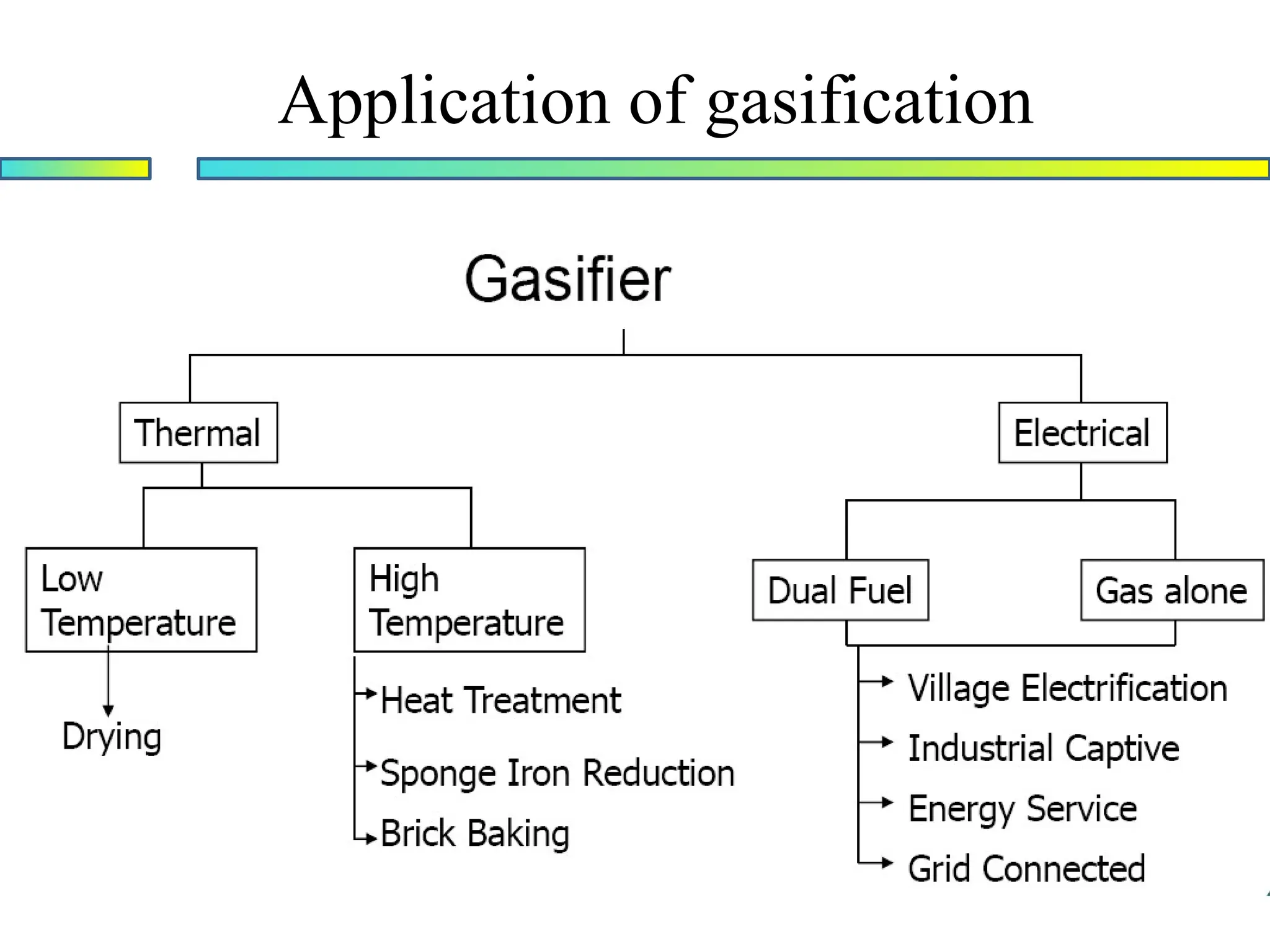
Application of gasification
Processthat converts solid fuel to gaseous fuel
Used in heat application
• Low temperature – drying, etc
• High temperature – furnaces, kilns, etc
Used in an internal combustion engine for power
generation to substitute fossil fuel
• Diesel engine – for dual fuel application
• Gas engine – for single fuel
Application of gasification
Productionof fuel gas
• All types of gasifiers can provide producer gas for combustion
purposes, but for the sake of simplicity up-draught gasifiers are
preferred in small systems (below 1 MW thermal power), while
fluidised bed gasifiers are appropriate in power ranges above
this level.
• Most conventional oil-fired installations can be converted to
producer gas.
• The most potential users of low-calorific fuel-gas in the future
are expected to be found among the following industries:
metallurgy, ceramic, cement, lime and pulp. In these industrial
branches the conversion of kilns, boilers and driers from oil to
fuel gas operation is in principal a quite simple operation.
57.
Application of gasification
Productionof mechanical or electrical power in
stationary installations
• Gasifiers connected to stationary engines offer the possibility
of using biomass to generate mechanical or electrical power in
the range from a few kW up to a few MW.
• Producer gas of engine quality needs a sufficiently high
heating value (above 4200 KJ/m³ ), must be virtually tar and
dust free in order to minimize engine wear, and should be as
cool as possible in order to maximize the engine's gas intake
and power output.
58.
Application of gasification
Mobileapplications
•The use of down-draught gasifiers fuelled by wood or
charcoal to power cars, lorries, buses, trains, boats
and ships has proved its value and at least one
European country (Sweden) maintains plans for large-
scale production in case of an emergency. This
technique is currently being studied for powering of
tractors (Switzerland, France, Finland, Netherlands) as
well as small vans and boats (Philippines) and lorries
(Sri Lanka).
59.
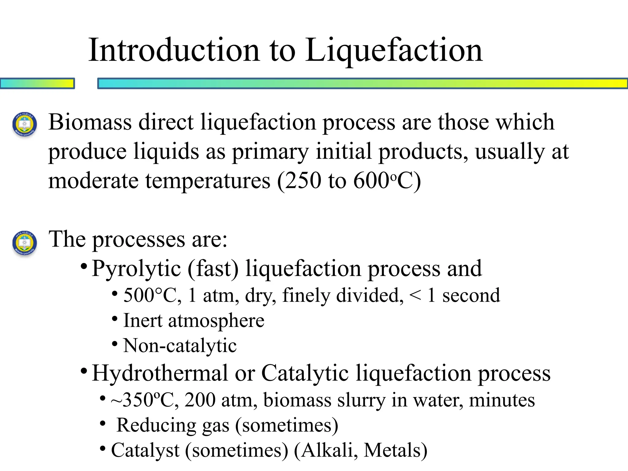
Introduction to Liquefaction
Biomassdirect liquefaction process are those which
produce liquids as primary initial products, usually at
moderate temperatures (250 to 600o
C)
The processes are:
•Pyrolytic (fast) liquefaction process and
• 500°C, 1 atm, dry, finely divided, < 1 second
• Inert atmosphere
• Non-catalytic
•Hydrothermal or Catalytic liquefaction process
• ~350ºC, 200 atm, biomass slurry in water, minutes
• Reducing gas (sometimes)
• Catalyst (sometimes) (Alkali, Metals)
60.
Introduction to Liquefaction
Liquidfuels derived from Biomass are expected to
contribute significantly to the energy potential from
this resource
Advantages
• High energy content (8500Btu/lb) that enables
economical transportation and storage
• Match existing end-user patters, particularly in
the transport sector
Introduction to Liquefaction
WhatKind and Degree of Upgrading?
First, determine final use …
• Fuel for boilers
• Fuel for turbines
• Fuel for internal combustion engines
• Recovery of chemicals
Determine upgrading requirement …
• Physical upgrading
• Solvent addition
• Separations
• Chemical/catalytic upgrading
63.
Introduction to Liquefaction
Morereading on Liquefaction
Ayhan Demibras, “Biorefineries for biomass
upgrading facilities”, 2010, Springer-Verlag,
London
Pp139-150
![Energy Balance (cont.)
Design of Gasifiers (cont.)
Heat of Reaction
The heat gained or lost in a chemical reaction is called heat of reaction
Heat of reaction = [the sum of all heats of formation of all products] -
[the sum of all heats of formation of all reactants]
To calculate it for gasification, we consider an overall gasification
reaction where 1 mol of biomass (CaHbOc) is gasified in α mols of steam
and β mols of oxygen
The overall equation is
Q is the net heat supplied to the reactor](https://image.slidesharecdn.com/lecture5-250709130034-f962dc36/75/lecture-5-Gasification-and-Liquefaction-50-2048.jpg)