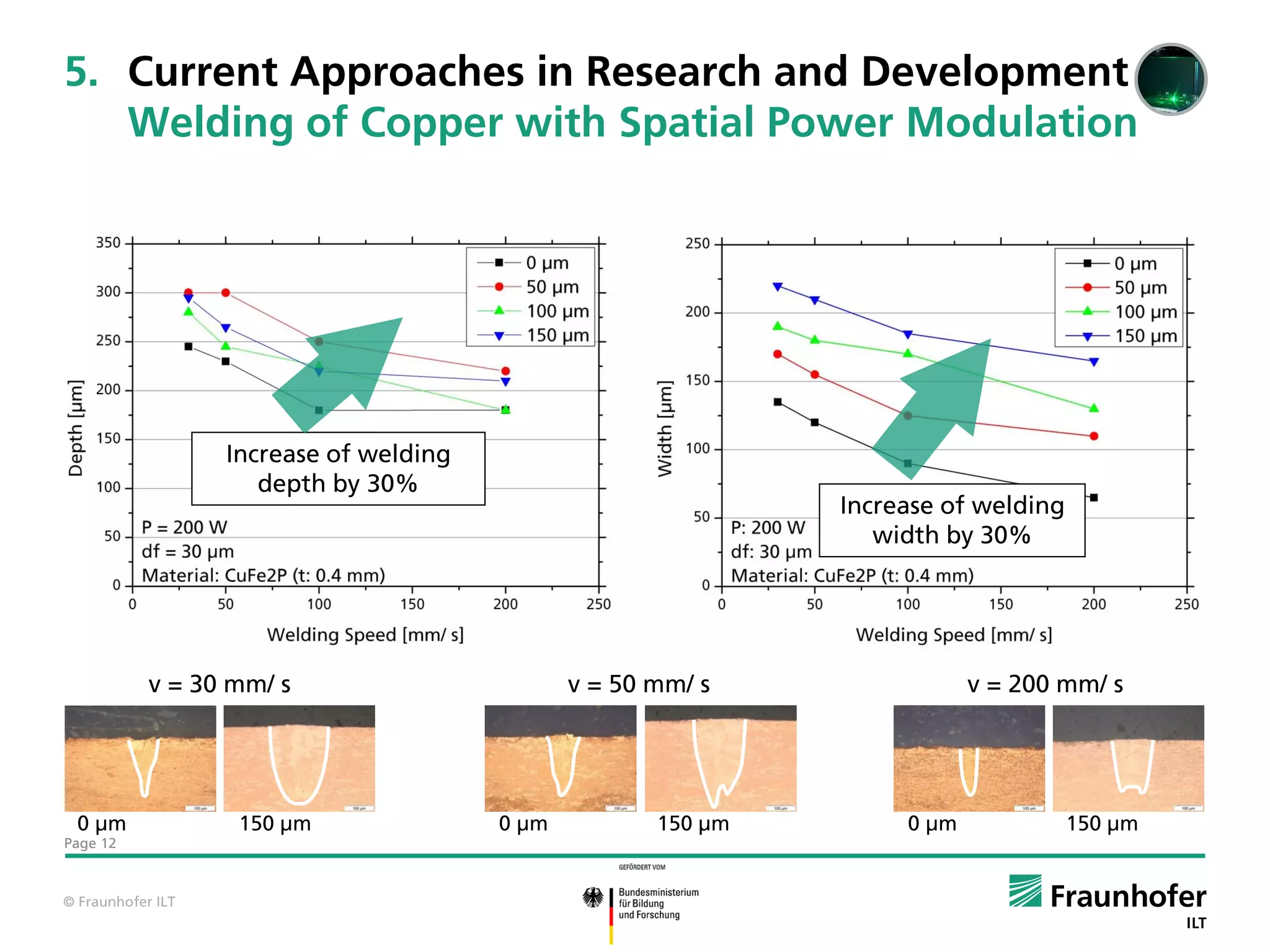
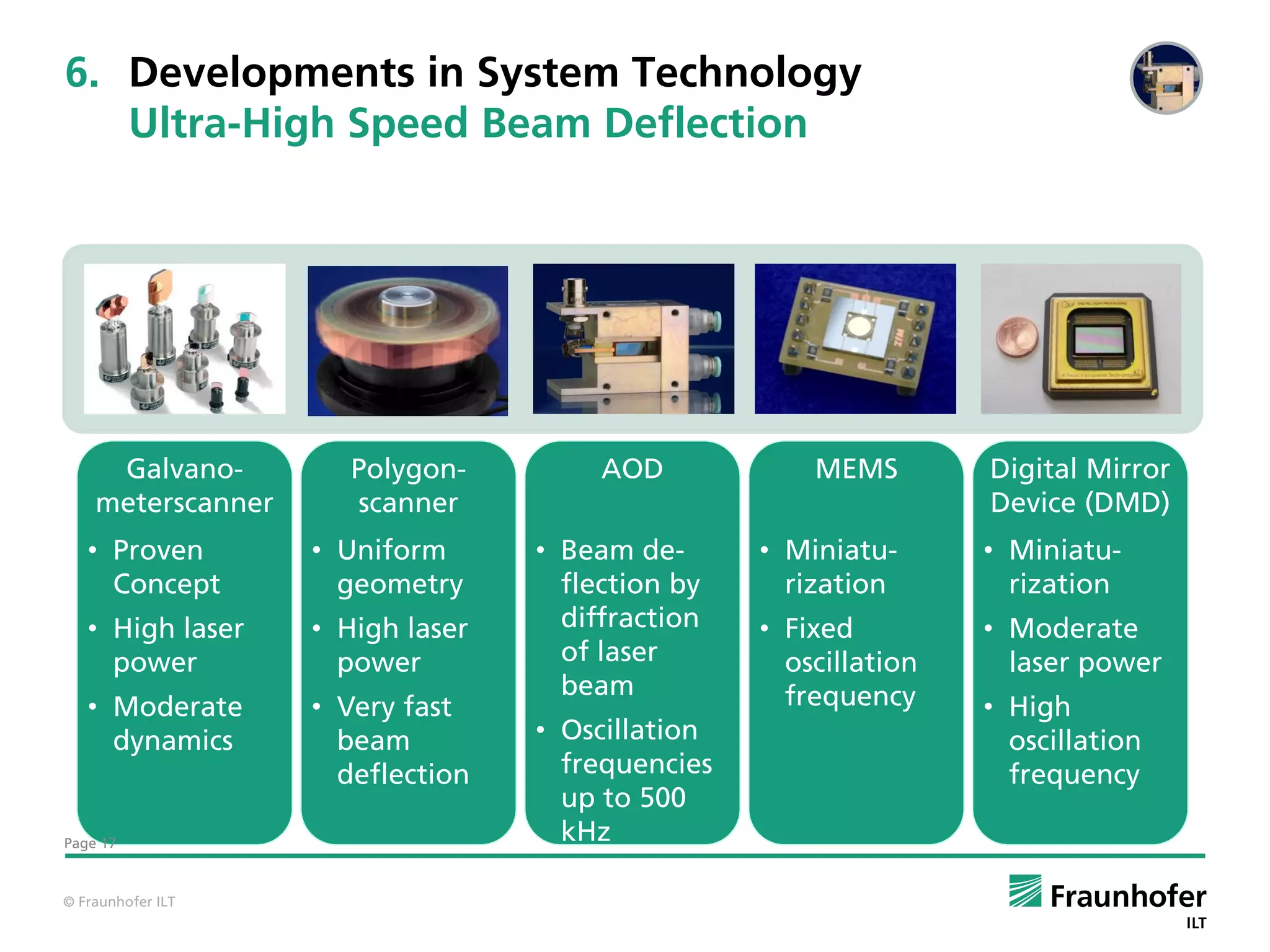
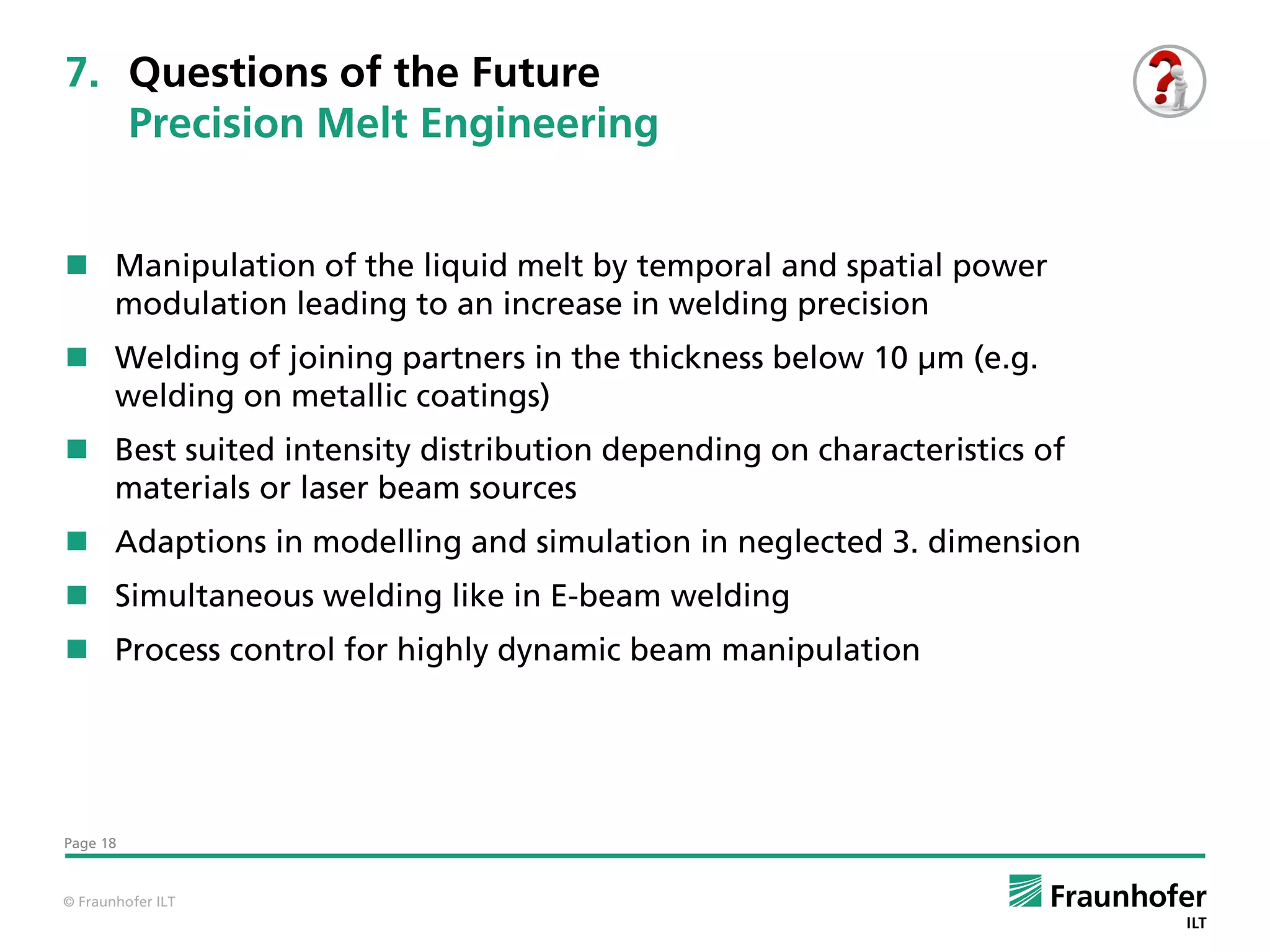
This document discusses laser micro joining processes and applications in research and development. It outlines laser beam sources and beam manipulation strategies used for micro joining applications in energy storage, electronics, and lightweight construction. Current approaches in research include welding copper with spatial and temporal power modulation to increase weld depth and quality. Developments aim to enable precision melt engineering through dynamic beam manipulation and modeling of laser micro joining processes.
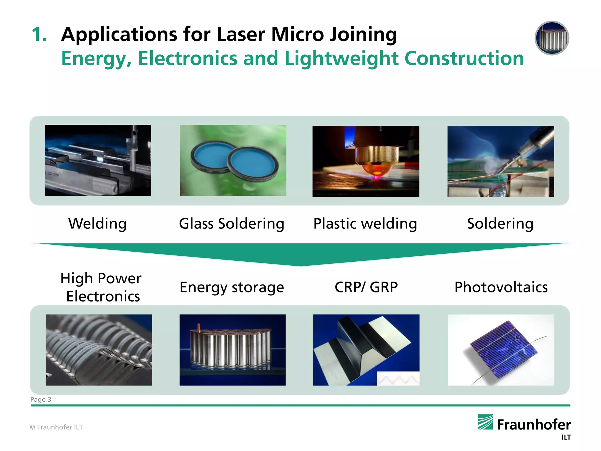
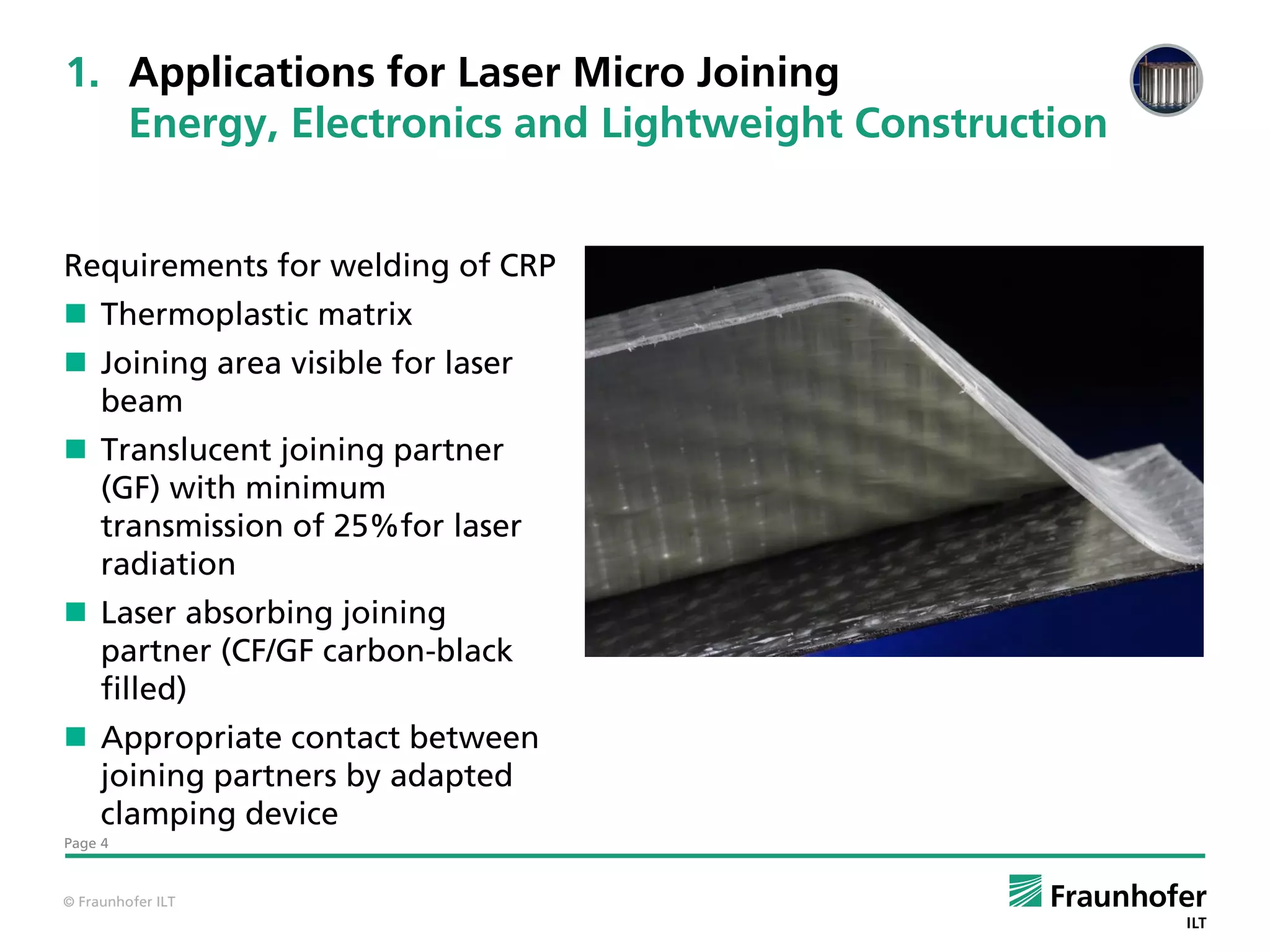
![1. Applications for Laser Micro Joining
Energy, Electronics and Lightweight Construction
15
Laser Beam
Penetration
Line Energy [J/m m ]
Al 0,5
Conductors 10 Cu 0,3
5
Pouch Cell
Plate Cooler Not Connected
0
0 50 100 150 200
Feed [mm/s]
Welding geometry:
Overlap, Al conductor
top Requirements for welding process
Linear weld seam Stabilized process in small working range
Parameter:
Enlarged cross-section for enhanced conductivity
df = 80 µm
P = 500 - 1 000 W Welding of dissimilar materials
Page 5 v = 50 - 200 mm/s
© Fraunhofer ILT](https://image.slidesharecdn.com/13-00heermehlmann-121212095005-phpapp01/75/Benjamin-Mehlmann-Fraunhofer-Institute-5-2048.jpg)
![3. Beam Manipulation Strategies
Variable Intensity Profile in Time and Space
Intensität [W/ cm²] Intensität [W/ cm²]
0,0E+00 0,0E+00
0,2 0,2 2,8E+03 1,9E+03
5,5E+03 3,8E+03
8,3E+03 5,6E+03
1,1E+04 7,5E+03
1,4E+04 9,4E+03
1,7E+04 1,1E+04
y [mm]
y [mm]
1,9E+04 1,3E+04
0,0 0,0 2,2E+04 1,5E+04
2,5E+04 1,7E+04
2,8E+04 1,9E+04
3,0E+04 2,1E+04
3,3E+04 2,3E+04
3,6E+04 2,4E+04
3,9E+04 2,6E+04
-0,2 -0,2 4,1E+04 2,8E+04
4,4E+04 3,0E+04
4,7E+04 3,2E+04
-0,2 0,0 0,2 -0,2 0,0 0,2
x [mm] x [mm]
Beam Shaping Spatial Power Temporal Power
Modulation Modulation
• M-Shape • Fast Beam • Rising Time
• Circle Deflection • Frequency
• Diffractive Optical • Lissajous- • Different
Elements (DOE) oscillation modulation shapes
geometries
• Amplitude
• Frequency
• Amplitude
Page 8
© Fraunhofer ILT](https://image.slidesharecdn.com/13-00heermehlmann-121212095005-phpapp01/75/Benjamin-Mehlmann-Fraunhofer-Institute-8-2048.jpg)