This document provides technical specifications and instructions for an Internet Gateway device that connects Z-Wave devices to the Internet. The gateway operates on 12Vdc, has a wireless range of 150 meters, and can configure, include, exclude and control any Z-Wave device. It connects to a server to apply rules and share information with other devices in the Z-Wave network. Lights on the gateway indicate its operating status and connections.
This document provides instructions for setting up and using the Popp HUB home automation controller. The Popp HUB is a Z-Wave Plus smart home controller that can connect and control various Z-Wave devices within a home automation network. It has a web-based user interface that allows monitoring and controlling connected devices from any browser or mobile app. The three main steps to set up the Popp HUB are to connect it to the local network, access the web UI to register the device, and begin adding Z-Wave devices which will appear as controllable elements within the interface. The interface provides options to organize devices into rooms, create scenes and automations using apps, and monitor activity through an event log.
Development of a Low Cost, Reliable & Scalable Home Automation System.imtiyazEEE
The slide is based on construction of a home automation system that will remotely switch ON/OFF any household, industrial or official appliances connected to it, using Arduino UNO, application on a smartphone and visual status of the loads for the feedback.
This document provides instructions for setting up and using a Popp HUB home automation controller. The Popp HUB is a Z-Wave gateway that can control smart home devices and define scenes. Setup involves connecting the HUB to a local network, accessing the web interface, and registering the device. The HUB interface allows adding and controlling Z-Wave devices, creating rooms and dashboard widgets. Additional functionality is provided through apps that integrate other technologies and automation logic.
ELECTRONICS PROJECT REPORT OF HOME AUTOMATION CUM BUILDING SECUIRITYEldhose George
This document summarizes a home security and automation system that uses an intruder detection system and cameras for security, and controls lights, garden watering, and a water pump for automation. The security section uses IR sensors and cameras to detect intruders and monitor areas. The automation section controls lights, garden watering using a solenoid valve, and a water pump for an overhead tank. The system is controlled by a microcontroller and includes circuits for sensors, cameras, relays, and a power supply.
This document provides instructions for setting up and using an 802.11g wireless USB adapter. It includes sections on unpacking the adapter, installing the hardware by plugging it into a USB port, installing the associated software and drivers from an included CD, and using the wireless utility to configure settings like the SSID and security. The utility allows viewing connection information, changing basic and advanced wireless settings, surveying available networks, and viewing adapter details. Technical specifications for the adapter are provided at the end, including its wireless standards, data rates, operating temperature range, dimensions and certifications.
This document describes a project to control electrical appliances in a home remotely using a microcontroller and PC. A microcontroller like the AT89S52 is used to interface with devices via relays and receive commands from a PC through an RS-232 serial connection. The MAX232 chip converts signals between the RS-232 and microcontroller levels. Based on commands from the PC, the microcontroller can turn appliances on and off and send back status updates. This allows remote control and monitoring of devices for applications like smart homes and industrial automation.
This document provides details on a home automation project using Arduino. The project aims to design a kit that can control AC loads like lights and fans from an Android phone using an Arduino microcontroller. It discusses the components required like a step-down transformer, Arduino, relays, Bluetooth module, and loads. The circuit diagram and Arduino code for controlling relays on button press from a Bluetooth-connected Android app are also provided. The conclusion states that the system provides a flexible and attractive user interface for home automation compared to other systems.
Office automation refers to the varied computer machinery and software used to digitally create, collect, store, manipulate, and relay office information needed for accomplishing basic tasks. ... Office automation was a popular term in the 1970s and 1980s as the desktop computer exploded onto the scene.
This document describes a home automation system that allows control of appliances like lights and fans from an Android mobile phone using Bluetooth. The system uses an 8-bit microcontroller with Bluetooth module to wirelessly communicate with the mobile phone. Home appliances are connected to the microcontroller board, which receives on/off commands from a mobile app to control the appliances. Feedback is provided on the device status by lighting LEDs on the microcontroller board. The system provides a low-cost way to automate home devices using a mobile phone over Bluetooth wireless technology.
This document is a report on a wireless based control project submitted for a Bachelor of Technology degree. It describes a wireless secured lock system using an AT89S52 microcontroller that allows only authorized persons to access appliances via entering a code on a keypad. The system uses RF transmission at 433MHz between a transmitter with an encoder, and a receiver with a decoder connected to the microcontroller. If the entered code matches the stored code, the microcontroller activates a relay to power the appliance. The report includes block diagrams of the system components, descriptions of the microcontroller and other ICs, the circuit diagram, and the software flowchart.
Home automation system using arduino with androidrahul takalkar
This document describes a graduation project to create a home automation system using an Arduino microcontroller and an Android application. The system allows users to control home appliances like fans, lights and motors remotely using their smartphone. It discusses the hardware and software components, including the Arduino, mobile phone, and local server. The document outlines how sensors send data to the Arduino, which then communicates with the mobile phone via the local server. It also provides block and circuit diagrams, screenshots of the Android application interface, and concludes with limitations and suggestions for future work.
This document presents a project on digital home automation using Arduino Bluetooth. The project was submitted by Shishupal Kumar and Sahila Sadaf to their professor Dr. Manikant Kumar. The project uses an Arduino UNO microcontroller board along with an HC-05 Bluetooth module to control 4 loads or appliances remotely via a smartphone. The circuit diagram and code are provided, along with descriptions of the components used. Potential limitations include a limited Bluetooth range and needing continuous power. Advantages are that the system is robust and easy to use from a smartphone. Applications include smart home automation by adding sensors to control lighting, temperature and more remotely.
This document provides instructions for setting up a wireless router. It describes what is included in the package, the parts of the wireless router, and the information needed from the Internet Service Provider before beginning setup. There are two methods for setup outlined: 1) using the Smart Wizard on the included CD for easy, automatic setup or 2) a manual setup by connecting the router to a modem and entering network settings. The document also provides troubleshooting tips and specifications for the wireless router.
DTMF based home automation without using Microcontrollerprasanth nani
This document describes a DTMF-based home automation system that allows controlling home appliances wirelessly using a mobile phone. It works by using a DTMF decoder chip to decode tones from the phone dial pad and trigger relays connected to devices. The system has advantages like wireless control and energy savings but limitations like limited number of controllable devices and lack of feedback. It finds applications in homes and industries for remote control of electrical systems.
This project uses X Bee wireless modules to control devices remotely with feedback. The transmitter unit takes input from switches and sends commands via an X Bee module. The receiver unit receives the commands via its X Bee module and controls devices like relays. The status of devices is displayed on an LCD. X Bee modules allow bidirectional wireless communication and are configured using AT commands to control devices remotely over short ranges.
This project created a graphical user interface in MATLAB to control an Arduino board. The GUI contains pushbuttons that send signals to the Arduino via serial communication, causing it to activate different output pins and LEDs. This demonstrates how MATLAB can synchronize with an Arduino to control its physical outputs. Potential applications include using the same approach for home automation by connecting sensors and appliances to the Arduino. The main challenge was identifying the correct serial port between the computer and Arduino.
gui based device controller using matlab Major presentationPalak Sinha
major presentation on graphical user interface developing in matlab to control the device control like arduino output , for extending it to home automation etc.
International Journal of Engineering Research and DevelopmentIJERD Editor
Electrical, Electronics and Computer Engineering,
Information Engineering and Technology,
Mechanical, Industrial and Manufacturing Engineering,
Automation and Mechatronics Engineering,
Material and Chemical Engineering,
Civil and Architecture Engineering,
Biotechnology and Bio Engineering,
Environmental Engineering,
Petroleum and Mining Engineering,
Marine and Agriculture engineering,
Aerospace Engineering.
Project Report on HOME AUTOMATION USING DTMF.
The Project “Home Automation using mobile communication” has different sections such as:
1.Microcontroller
2.DTMF decoder
3. Relays
. This project we propose a unique System for Home automation utilizing Dual Tone Multi Frequency (DTMF) that is paired with a wireless module to provide seamless wireless control over many devices in a house. This user console has many keys, each corresponding to the device that needs to be activated. The encoder encodes the user choice and sends via a GSM transmitter. The GSM receiver receives the modulated signal and demodulates it and the user choice is determined by the DTMF decoder. Based upon this the required appliance is triggered.
This document describes a DTMF based home appliance control system using an 8051 microcontroller. The system uses DTMF tones sent over telephone lines to remotely control appliances connected to relays. When a user calls into the system and enters a DTMF code, the microcontroller decodes the tones using a DTMF decoder chip and triggers the corresponding relay to control the appliance. The system is designed to provide low-cost remote control and home security through dedicated passwords known only to authorized users.
This document provides an overview and introduction to a digital home automation project using Arduino and Bluetooth. The project aims to develop a home automation system that allows appliances to be remotely controlled via an Android smartphone application. Key components include an Arduino Uno microcontroller, HC-05 Bluetooth module, relays, and an Android app. The system allows electrical appliances like lights and fans to be switched on or off from a smartphone. The Arduino code controls the relays based on commands received over Bluetooth from the Android app.
Presented here is a home automation system using a simple Android app, which you can use to control electrical appliances with clicks or voice commands. Commands are sent via Bluetooth to Arduino Uno. So you need not get up to switch on or switch off the device while watching a movie or doing some work.
Group NO:03 has 6 members who are designing an electronic code lock system using an AT89S52 microcontroller and a room light controlling system using sensors. The code lock system only unlocks with a predefined code and alerts users with a buzzer if the wrong code is entered. The light system automatically turns lights on when movement is detected and off when the room is empty. The group aims to increase security and automatically manage room lighting and electricity usage. Future plans include adding voice password and fan/AC control capabilities.
This document summarizes a paper that designed and implemented fuzzy logic controllers for DC motor speed control using MATLAB-GUI. The authors developed hardware to interface a DC motor with a computer. They designed fuzzy logic controllers and integrated fuzzy logic controllers in MATLAB to control the motor speed. The MATLAB GUI allows tuning controller parameters in real-time and observing the motor performance. Experimental results showed the integrated fuzzy logic controller provided better performance than the fuzzy logic controller in terms of rise time, settling time, overshoot and undershoot for speed control applications.
A Smart Handheld Measuring and Testing Electronic Device with Touch ScreenIJTET Journal
Hand in hand instrument replaces the old traditional way of measuring and testing in colleges and helps in easy way of understanding theoretical concepts based on practical knowledge. As there occurs shortage of instruments, long duration of calculation, large occupation of space, low accuracy, inconvenience come about in completing the work. A single Smart device which is a multipurpose handheld instrument overcomes the above difficulties and helps in measuring voltage, current, resistance, frequency, temperature, speed, sound and to observe waveforms for engineering students in the laboratories. In a single ARM Cortex M3 microcontroller all measurements are done and displayed within a fraction of time in the TFT graphical LCD display. The data and waveforms from oscilloscope can be saved and retrieved for future analyzing purpose which is done using a Micro SD memory card. The device is fully operated with touch screen and touch buttons. The device works with help of LPC1313, a powerful 32-bit ARM Cortex-M3 microcontroller from NXP Semiconductors.
This document discusses Telefonica España's smart home and small office/home office (SOHO) strategy and services. It outlines how their end-to-end solution allows other companies to offer smart home services using Telefonica's infrastructure, including a wireless plug, sensors, apps, and support. Specific services highlighted include Powerhouse for energy monitoring and control, and Smart Climate Center for remote heating/cooling control.
OSGi Community Event 2010 - Using OSGi for the realization of home automation...mfrancis
OSGi is well-suited as an execution environment for home automation systems due to its support for Java, dynamic modularity, and services needed for residential devices. OSGi allows devices like Zigbee, Z-Wave, and KNX to be supported and is being adopted by telecom companies and standards bodies for residential gateways. Example home applications that could be built on OSGi include home automation, security, healthcare, and media services. Key aspects in designing an OSGi-based home automation system include abstracting device layers, realizing automation logic, and managing configuration.
This document provides steps for configuring a PPTP VPN connection on a Mac. It instructs the user to select System Preferences and Network, add a new VPN connection, select PPTP as the VPN type, enter login credentials, enable sending all traffic over the VPN, and connect to the VPN from the status bar icon.
We have a convergence of crises: Food, Fuel, and Finance. So, we need a solution that is converging that addresses the Local, Global and Cosmic aspects which lead to Survive / Understand / Love. It is coming from SOHO, Sun and Soul. Because, ultimately we (each and every one of us):
(1) Must have our own individual Small Office Home Office (Survive)
(2) Appreciate the Sun: its place in the world / ecology (Understand)
(3) Find our own Salutogenesis or Soul: Wisdom & Love (Love)
It is all about the Big Three:-
(1) I (Self) / Its (Nature) / We (Culture)
(2) Profit / Planet / People or Economy / Ecology / Equity
(3) Body / Mind / Spirit
(4) Beauty / Truth / Goodness
The document discusses establishing a small home office (SOHO) using a lean startup methodology to achieve financial freedom through international trading opportunities. It describes developing the necessary mindset, skills, and support systems, including coworking spaces, training, funding sources, and government assistance. Examples are given of monetizing passions through self-publishing, affiliate marketing, and ecommerce. The path is described as starting small and expanding through different stages until achieving financial freedom and transitioning to full-time passion-based work through lifelong learning.
The document summarizes a government-funded project in Norway called "Manage Smart in Smart Grid". The 3-year project has a budget of 17.5 million Norwegian krone and is focused on developing commercial models, systems and services for innovation in smart grids. It aims to use homes and buildings as interacting systems, develop smart software to trade energy in microgrids, and provide services that control energy use through advanced metering infrastructure. The goal is to advance the smart grid and enable real-time energy management, demand response and distributed generation.
Smart Grid - Overview of Market Segment & Technology David Sidhu
This document provides an overview of the smart grid market and technologies. It discusses the US electricity sector and how electricity is delivered through transmission and distribution systems. The global smart grid market is projected to grow substantially between 2009-2014, driven by investments in smart metering, communications, and other technologies. The document describes various smart grid technologies like smart meters, demand response, and dynamic pricing programs. It also outlines the evolution of demand response equipment from simple switches to embedded controls with two-way communication.
Wall plug switch with metering aeon labs v2 manualDomotica daVinci
This document provides instructions and specifications for the Aeon Labs Inline Smart Energy Switch Z-Wave actuator. The switch can be included in a Z-Wave network to enable wireless control and energy monitoring of connected devices. It supports various Z-Wave protocols and configuration parameters that allow it to report energy usage to compatible controllers. Proper installation and disposal guidelines are also outlined.
The document provides instructions for installing and setting up an EnGenius EWS-series wireless management switch. It describes unpacking the package contents, installing the switch on a flat surface or rack, connecting devices to the switch ports, and accessing the switch's web interface using a default IP and login credentials. It also gives steps for locating, adding, and managing wireless access points and configuring switch settings through the browser-based user interface.
Here are the key components of a regulated power supply:
- Transformer - Steps down the high voltage mains power to a lower voltage.
- Rectifier - Converts the AC output of the transformer to DC using diodes.
- Filtering - A capacitor filters the DC output to smooth the voltage.
- Regulator - A voltage regulator IC like the 7805 regulates the filtered DC voltage to a constant value, in this case 5V.
- Heat sinking - The regulator needs to be mounted to an adequate heat sink to dissipate heat from regulating the voltage.
- Input and output terminals - Allow connection of input voltage and output regulated voltage.
So in summary, a regulated power supply takes
The document provides a quick installation guide for the EnGenius EWS-series wireless management switches and access points. It includes instructions on unpacking the package contents, requirements for installation location, how to mount the switch on a flat surface or rack, how to connect devices to the switch and manage it through a web browser interface. It also describes how to locate, add and manage wireless access points connected to the switch through the management interface.
The document provides a quick installation guide for the EnGenius EWS-series wireless management switches. It includes unpacking the package contents, instructions for installing the switch on a flat surface or rack, connecting devices to the switch, and managing the switch and connected access points through a web browser-based graphical user interface. Key steps are to connect the switch to a power source, connect a computer to the switch via Ethernet, and log into the switch's IP address in a web browser using the default username and password.
This device is a Z-Wave carbon monoxide sensor that can be included in a Z-Wave network to wirelessly report carbon monoxide levels and alarm conditions. It combines a certified carbon monoxide detector with a Z-Wave module. When carbon monoxide levels reach certain thresholds, the sensor will send an alarm to the central controller and can trigger other Z-Wave devices. The sensor can also report tamper detection, low battery, and malfunctions.
Dry contact sensor with temperature sensor start guideDomotica daVinci
This document provides instructions for a Z-Wave binary sensor, thermostat, and temperature sensor device. It describes how to include the device in a Z-Wave network, set up its temperature monitoring and thermostat functions, and configure its battery-saving wakeup intervals. The document also summarizes the device's technical specifications and supported Z-Wave command classes.
Manual Steinel l 810 led i hf (outdoor light with led)Domotica daVinci
This document provides instructions and information for a Z-Wave light dimmer. It includes details about installation, inclusion in a Z-Wave network, configuration parameters, and operation. The light dimmer can be controlled through the Z-Wave network or manually using buttons, and includes settings for detection range, light threshold, dimming levels, and more.
The document provides a quick installation guide for the EnGenius EWS7952FP wireless management switch. It includes instructions on unpacking the package contents and installing the switch on a flat surface or rack. It also gives steps for connecting the switch and other devices, and accessing the web-based user interface to manage and configure the switch and any connected wireless access points. Key functions covered include locating and adding access points for management, and configuring network settings for the devices.
This document provides information about the Danfoss Hydronic Controller 10, a Z-Wave device for controlling hot water underfloor heating systems. It can control up to 10 outputs and includes functions like pump control, heating/cooling, and individual room temperature control. The document explains how to include the controller in a Z-Wave network and configure its settings, and provides the device's technical specifications.
Wall plug switch with metering po pp start guideDomotica daVinci
This Z-Wave plug-in switch can control electric devices up to 3000W and also measures power consumption. It communicates via the Z-Wave wireless protocol and can join a Z-Wave network through inclusion. The switch can be manually controlled with its button and reports power usage to the Z-Wave controller. It has configuration parameters to customize power and energy reporting intervals.
IRJET - IoT based Home Automation System through Voice Control using Google A...IRJET Journal
This document describes an IoT-based home automation system that allows control of electrical appliances using voice commands through a Google Assistant app. The system uses an Arduino microcontroller connected to ESP8266 WiFi modules and relays to control appliances. Users can control lights, fans, and other devices remotely using the Blynk app on their smartphone, which sends commands to the Arduino via ESP8266. This provides convenience and saves energy by automating appliance control. The system was tested successfully to control loads by voice commands through the Blynk and Google Assistant apps.
The document provides information about a Z-Wave glass surface 2 channel touch panel switch, including:
1) It can switch two separate loads up to 1100W and is designed for UK pattress boxes.
2) It uses Z-Wave wireless communication at 868.42MHz to control associated devices or scenes.
3) It must be included in a Z-Wave network by a primary controller to communicate with other devices.
The document provides instructions for setting up and configuring the INFINITY universal wireless Wiegand bridge device set. The set consists of a master device and slave device. The master connects to an access control system controller and the slave connects to door equipment. The devices provide encrypted wireless communication between the controller and door. Configuration is done through a web interface by connecting to the device's local WiFi hotspot for a limited time after startup. Key settings include matching the communication channel number and encryption key between paired devices.
IRJET- IoT based System for Smart and Secured HomeIRJET Journal
This document describes an Internet of Things (IoT) based system for creating a smart and secure home. The system uses an Arduino Due microcontroller connected to Wi-Fi through an ESP8266 module to control appliances in the home like lights, fans, and motors. Sensors like a temperature sensor, water level sensor, and gas sensor are used to automate controls and add security. The system allows multiple users to control appliances through a smartphone app or web interface connected to the Arduino's IP address. This makes the home intelligent and energy efficient while improving security.
This document provides instructions for a Z-Wave thermostat and sensor device. The device can measure temperature, detect binary sensor states, and control heating devices as a thermostat. It communicates using the Z-Wave wireless protocol and operates on batteries. The summary includes instructions for inclusion, exclusion, configuration, and operating the temperature, binary sensor, and thermostat functions.
IRJET - IoT based Home Automation using ATmega328 MicrocontrollerIRJET Journal
This document describes an IoT-based home automation system using an ATmega328 microcontroller. The system allows controlling home appliances like lights and fans remotely over WiFi. An ATmega328 microcontroller communicates with an ESP8266 WiFi module to send and receive data from a server and control relays connected to appliances. The system provides a user-friendly Android app interface to control appliances from anywhere. It discusses the components used - ATmega328, ESP8266, relays, voltage regulators. The system aims to automate homes and control appliances with clicks from a smartphone for convenience and energy savings.
This device is a portable Z-Wave wall controller that can control other Z-Wave devices and act as a primary or secondary controller in a Z-Wave network. It includes devices by pressing the Include button for 2 seconds and issues node information frames with triple clicks of the Up/Down buttons. The controller runs on 2 AAA batteries and can be mounted on flat surfaces.
Similar to Benext Z-Wave Gateway Manual English (20)
The 2CH Dimmer Module allows manual control of lights through a push switch and app control. It can control up to two lighting circuits and provides options for permanent on/off or dimming control through short or long button pushes. Installation requires turning off power and properly wiring the unit according to diagrams. The module can be reset through a long button press or external button presses and pairs with Zigbee gateways through a learning mode button hold.
Zi-Stick is a self-powered Zigbee 3.0 USB adapter that is used to control actuators and sensors in a Zigbee network. It connects to a computer via USB and appears as a virtual serial or COM port. The user guide provides instructions for installing any necessary drivers, identifying the Zi-Stick's COM port, and connecting it to software like Home Assistant or OpenHAB. Safety information is also included, noting that the Zi-Stick should be used indoors and away from heat or moisture.
This document provides installation and operation instructions for a BRT-100 radiator thermostat in French. It includes:
1. An introduction and welcome message thanking the customer for their purchase.
2. Technical characteristics and features of the thermostat such as LED display, color display, curved design, energy efficient battery that lasts 1 year.
3. Step-by-step instructions for installation including selecting the correct adapter, installing the mounting plate and battery, and connecting the thermostat.
Cherubini Meta Z-Wave Double Switch A510083-84-90Domotica daVinci
Este documento proporciona instrucciones para un actuador con dos salidas independientes de 230V. Incluye especificaciones técnicas, información de seguridad, diagramas de conexión e instrucciones de instalación, control y configuración. El dispositivo permite controlar dos cargas de forma independiente a través de radio o pulsador y puede integrarse en sistemas domóticos Z-Wave.
Este documento proporciona instrucciones para el uso de un enchufe inteligente. Describe las especificaciones técnicas del dispositivo, cómo incluirlo y excluirlo de una red Z-Wave, cómo controlarlo y leer sus parámetros eléctricos, y cómo configurar sus alarmas y asociaciones con otros dispositivos.
Quinto Z-Wave Heltun_HE-RS01_User_Manual_B9AH.pdfDomotica daVinci
The document provides instructions for installing and operating the HE-RS01 five-channel relay switch. Key details include:
- The HE-RS01 can control up to five on/off devices or combinations of on/off and two-direction motor devices.
- It has five configurable relay outputs, two independent inputs, and supports schedules, motor control, and association with other Z-Wave devices.
- Installation requires connecting power, load, and external switch wires per the provided diagrams and safely turning power back on at the circuit breaker.
- The HE-RS01 can be included in a Z-Wave network and each relay and external input is configurable for different control modes.
Z-Wave Fan coil Thermostat Heltun_HE-HT01_User_Manual.pdfDomotica daVinci
The document provides a user manual for the HE-HT01 thermostat. It has 6 operating modes including Comfort, Schedule, Floor Drying, Energy Saving, Vacation, and Manual. It can be installed flush in an electrical junction box and controls heating systems up to 16A. The thermostat integrates Z-Wave technology for smart home control and has touch buttons, LCD display, and sensors for temperature, humidity, and energy usage.
The document provides instructions for an energy-saving radiator thermostat that uses Z-Wave wireless technology. It includes details on installation, setup, operation, and technical specifications. The thermostat can be added to a Z-Wave network to communicate with other devices and be controlled remotely. It offers functions like setting target temperatures, child lock, operating modes, and displaying network information.
The motion sensor user guide provides specifications and setup instructions. It detects motion within 10 meters at a 120 degree angle using Zigbee wireless communication. To set up, download the Smart Life app, register an account, add the Zigbee controller, then search for and add the motion sensor, which can be configured for various alarm settings and linkages within the app.
The document provides a user guide for the Aeotec Range Extender 7, which is a Z-Wave signal amplifier developed to extend the range of a Z-Wave network. It describes how to include the Range Extender in a Z-Wave network using either SmartStart or classic inclusion. It also explains how to control the LED, test connectivity health, remove the device from the network, and manually reset the Range Extender.
The document provides specifications for a Z-Wave multi-sensor device. It includes details on the device's library and command classes, Z-Wave network operation including button functions and LED indicators, association groups and commands, wakeup settings, battery information, sensor readings for temperature, humidity, light and UV, notification types, manufacturer information, and configuration parameters.
Z-Stick 7 is a Z-Wave USB adapter that allows users to control Z-Wave devices and sensors. It uses Series700 and Gen7 technology with SmartStart and S2 security. The guide provides instructions on installing drivers, adding the Z-Stick to home automation software as a primary or secondary controller, using serial API mode, development tools, and resetting the Z-Stick. Compatible software setup guides are also listed.
Optimal protection for critical loads. To limit starting currents on problematic devices, such as energy saving bulbs and fluorescent bulbs. Problematic devices, such as electronic ballasts, energy-saving light bulbs, incandescent bulbs, LED drivers, and switching power supplies, consume a lot of power during ignition due to the multiplication of current. nominal and can therefore destroy the switching relay.
With the ESB200 current limiter, the high current that can occur when switching on electronic devices is limited to a harmless value. It is also possible to limit the inrush current of incandescent lamps to give them a longer life. A protection fuse is also integrated. This starting current limiter can be plugged directly into the power supply circuit for loads up to 200 VA. This compact device can be installed very easily in junction and recessed boxes or in lamp boxes, for example. The device is easily installed in series with the load
wiDom Smart Roller Shutter Z-Wave Plus Module ManualDomotica daVinci
The document provides instructions for installing and operating the WiDom Smart Roller Shutter, a Z-Wave enabled device for controlling roller shutters, blinds, and curtains. It can accurately control opening and closing positions through local or remote commands. After an initial calibration, it identifies the position without sensors. Safety information warns that installation requires qualified electricians and live voltages are present. Installation instructions explain connecting it according to the diagrams and including it in a Z-Wave network. The LED status indicator shows inclusion status and communication events.
In his public lecture, Christian Timmerer provides insights into the fascinating history of video streaming, starting from its humble beginnings before YouTube to the groundbreaking technologies that now dominate platforms like Netflix and ORF ON. Timmerer also presents provocative contributions of his own that have significantly influenced the industry. He concludes by looking at future challenges and invites the audience to join in a discussion.
GraphSummit Singapore | The Future of Agility: Supercharging Digital Transfor...Neo4j
Leonard Jayamohan, Partner & Generative AI Lead, Deloitte
This keynote will reveal how Deloitte leverages Neo4j’s graph power for groundbreaking digital twin solutions, achieving a staggering 100x performance boost. Discover the essential role knowledge graphs play in successful generative AI implementations. Plus, get an exclusive look at an innovative Neo4j + Generative AI solution Deloitte is developing in-house.
Full-RAG: A modern architecture for hyper-personalizationZilliz
Mike Del Balso, CEO & Co-Founder at Tecton, presents "Full RAG," a novel approach to AI recommendation systems, aiming to push beyond the limitations of traditional models through a deep integration of contextual insights and real-time data, leveraging the Retrieval-Augmented Generation architecture. This talk will outline Full RAG's potential to significantly enhance personalization, address engineering challenges such as data management and model training, and introduce data enrichment with reranking as a key solution. Attendees will gain crucial insights into the importance of hyperpersonalization in AI, the capabilities of Full RAG for advanced personalization, and strategies for managing complex data integrations for deploying cutting-edge AI solutions.
Maruthi Prithivirajan, Head of ASEAN & IN Solution Architecture, Neo4j
Get an inside look at the latest Neo4j innovations that enable relationship-driven intelligence at scale. Learn more about the newest cloud integrations and product enhancements that make Neo4j an essential choice for developers building apps with interconnected data and generative AI.
TrustArc Webinar - 2024 Global Privacy SurveyTrustArc
How does your privacy program stack up against your peers? What challenges are privacy teams tackling and prioritizing in 2024?
In the fifth annual Global Privacy Benchmarks Survey, we asked over 1,800 global privacy professionals and business executives to share their perspectives on the current state of privacy inside and outside of their organizations. This year’s report focused on emerging areas of importance for privacy and compliance professionals, including considerations and implications of Artificial Intelligence (AI) technologies, building brand trust, and different approaches for achieving higher privacy competence scores.
See how organizational priorities and strategic approaches to data security and privacy are evolving around the globe.
This webinar will review:
- The top 10 privacy insights from the fifth annual Global Privacy Benchmarks Survey
- The top challenges for privacy leaders, practitioners, and organizations in 2024
- Key themes to consider in developing and maintaining your privacy program
For the full video of this presentation, please visit: https://www.edge-ai-vision.com/2024/06/building-and-scaling-ai-applications-with-the-nx-ai-manager-a-presentation-from-network-optix/
Robin van Emden, Senior Director of Data Science at Network Optix, presents the “Building and Scaling AI Applications with the Nx AI Manager,” tutorial at the May 2024 Embedded Vision Summit.
In this presentation, van Emden covers the basics of scaling edge AI solutions using the Nx tool kit. He emphasizes the process of developing AI models and deploying them globally. He also showcases the conversion of AI models and the creation of effective edge AI pipelines, with a focus on pre-processing, model conversion, selecting the appropriate inference engine for the target hardware and post-processing.
van Emden shows how Nx can simplify the developer’s life and facilitate a rapid transition from concept to production-ready applications.He provides valuable insights into developing scalable and efficient edge AI solutions, with a strong focus on practical implementation.
20 Comprehensive Checklist of Designing and Developing a WebsitePixlogix Infotech
Dive into the world of Website Designing and Developing with Pixlogix! Looking to create a stunning online presence? Look no further! Our comprehensive checklist covers everything you need to know to craft a website that stands out. From user-friendly design to seamless functionality, we've got you covered. Don't miss out on this invaluable resource! Check out our checklist now at Pixlogix and start your journey towards a captivating online presence today.
Generative AI Deep Dive: Advancing from Proof of Concept to ProductionAggregage
Join Maher Hanafi, VP of Engineering at Betterworks, in this new session where he'll share a practical framework to transform Gen AI prototypes into impactful products! He'll delve into the complexities of data collection and management, model selection and optimization, and ensuring security, scalability, and responsible use.
Goodbye Windows 11: Make Way for Nitrux Linux 3.5.0!SOFTTECHHUB
As the digital landscape continually evolves, operating systems play a critical role in shaping user experiences and productivity. The launch of Nitrux Linux 3.5.0 marks a significant milestone, offering a robust alternative to traditional systems such as Windows 11. This article delves into the essence of Nitrux Linux 3.5.0, exploring its unique features, advantages, and how it stands as a compelling choice for both casual users and tech enthusiasts.
“An Outlook of the Ongoing and Future Relationship between Blockchain Technologies and Process-aware Information Systems.” Invited talk at the joint workshop on Blockchain for Information Systems (BC4IS) and Blockchain for Trusted Data Sharing (B4TDS), co-located with with the 36th International Conference on Advanced Information Systems Engineering (CAiSE), 3 June 2024, Limassol, Cyprus.
Observability Concepts EVERY Developer Should Know -- DeveloperWeek Europe.pdfPaige Cruz
Monitoring and observability aren’t traditionally found in software curriculums and many of us cobble this knowledge together from whatever vendor or ecosystem we were first introduced to and whatever is a part of your current company’s observability stack.
While the dev and ops silo continues to crumble….many organizations still relegate monitoring & observability as the purview of ops, infra and SRE teams. This is a mistake - achieving a highly observable system requires collaboration up and down the stack.
I, a former op, would like to extend an invitation to all application developers to join the observability party will share these foundational concepts to build on:
GraphSummit Singapore | The Art of the Possible with Graph - Q2 2024Neo4j
Neha Bajwa, Vice President of Product Marketing, Neo4j
Join us as we explore breakthrough innovations enabled by interconnected data and AI. Discover firsthand how organizations use relationships in data to uncover contextual insights and solve our most pressing challenges – from optimizing supply chains, detecting fraud, and improving customer experiences to accelerating drug discoveries.
UiPath Test Automation using UiPath Test Suite series, part 5DianaGray10
Welcome to UiPath Test Automation using UiPath Test Suite series part 5. In this session, we will cover CI/CD with devops.
Topics covered:
CI/CD with in UiPath
End-to-end overview of CI/CD pipeline with Azure devops
Speaker:
Lyndsey Byblow, Test Suite Sales Engineer @ UiPath, Inc.
Sudheer Mechineni, Head of Application Frameworks, Standard Chartered Bank
Discover how Standard Chartered Bank harnessed the power of Neo4j to transform complex data access challenges into a dynamic, scalable graph database solution. This keynote will cover their journey from initial adoption to deploying a fully automated, enterprise-grade causal cluster, highlighting key strategies for modelling organisational changes and ensuring robust disaster recovery. Learn how these innovations have not only enhanced Standard Chartered Bank’s data infrastructure but also positioned them as pioneers in the banking sector’s adoption of graph technology.
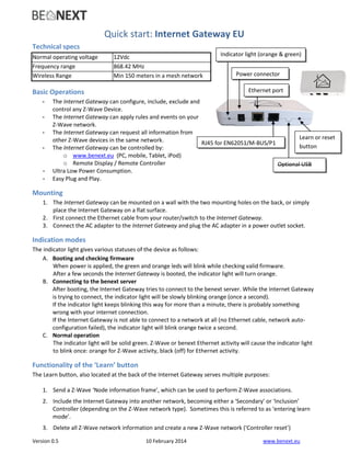
1. Version 0.5 10 February 2014 www.benext.eu
Quick start: Internet Gateway EU
Technical specs
Normal operating voltage 12Vdc
Frequency range 868.42 MHz
Wireless Range Min 150 meters in a mesh network
Basic Operations
- The Internet Gateway can configure, include, exclude and
control any Z-Wave Device.
- The Internet Gateway can apply rules and events on your
Z-Wave network.
- The Internet Gateway can request all information from
other Z-Wave devices in the same network.
- The Internet Gateway can be controlled by:
o www.benext.eu (PC, mobile, Tablet, iPod)
o Remote Display / Remote Controller
- Ultra Low Power Consumption.
- Easy Plug and Play.
Mounting
1. The Internet Gateway can be mounted on a wall with the two mounting holes on the back, or simply
place the Internet Gateway on a flat surface.
2. First connect the Ethernet cable from your router/switch to the Internet Gateway.
3. Connect the AC adapter to the Internet Gateway and plug the AC adapter in a power outlet socket.
Indication modes
The indicator light gives various statuses of the device as follows:
A. Booting and checking firmware
When power is applied, the green and orange leds will blink while checking valid firmware.
After a few seconds the Internet Gateway is booted, the indicator light will turn orange.
B. Connecting to the benext server
After booting, the Internet Gateway tries to connect to the benext server. While the Internet Gateway
is trying to connect, the indicator light will be slowly blinking orange (once a second).
If the indicator light keeps blinking this way for more than a minute, there is probably something
wrong with your internet connection.
If the Internet Gateway is not able to connect to a network at all (no Ethernet cable, network auto-
configuration failed), the indicator light will blink orange twice a second.
C. Normal operation
The indicator light will be solid green. Z-Wave or benext Ethernet activity will cause the indicator light
to blink once: orange for Z-Wave activity, black (off) for Ethernet activity.
Functionality of the ‘Learn’ button
The Learn button, also located at the back of the Internet Gateway serves multiple purposes:
1. Send a Z-Wave ‘Node information frame’, which can be used to perform Z-Wave associations.
2. Include the Internet Gateway into another network, becoming either a ‘Secondary’ or ‘Inclusion’
Controller (depending on the Z-Wave network type). Sometimes this is referred to as ‘entering learn
mode’.
3. Delete all Z-Wave network information and create a new Z-Wave network (‘Controller reset’)
Indicator light (orange & green)
Power connector
Ethernet port
RJ45 for EN62051/M-BUS/P1
Optional USB
Learn or reset
button
2. Version 0.5 10 February 2014 www.benext.eu
Send a node information frame
Sending a ‘node information frame’ can be necessary to perform for example associations with others Z-Wave
devices. However, under normal circumstances this should not be necessary since the Internet Gateway sets
up associations automatically after including a device to its network.
To send a node information frame, press the button once. The indicator light will blink orange once (if this
does not happen, press the button just a little longer).
Include the Internet Gateway into another network
In order to include the Internet Gateway into an already existing Z-Wave network, the following steps should
be taken:
1. Make sure that the Internet Gateway has no devices included (if it has, please exclude them first using
the benext Graphical Web-interface).
2. Set the Primary Controller (or an Inclusion Controller) of the existing network in inclusion mode.
3. Press and hold the Learn button, the indicator light will switch off.
4. Once the indicator light starts blinking orange, release the button. The indicator light starts blinking
orange two times every second.
If the indicator light blinks three times every second, the Internet Gateway is already included
in another network. Exclude it from the network using the benext Graphical Web-interface
(preferred), or delete all network information using the button (see below).
If the indicator light blinks eight times in one second, after which it returns to normal
operation mode, the Internet Gateway has other devices included in its network. Exclude
them first using the benext Graphical Web-interface.
5. After a few seconds, the indicator light should be orange for a full second, after which it returns to
normal operation. The Internet Gateway is successfully included in the network.
After 2 minutes, the indicator light blinks eight times in one second, after which it returns to
normal operation mode. This means inclusion has failed. Try again and make sure the
controller of the other network is reachable and in inclusion mode.
Delete all Z-Wave network information and create a new network
In order to remove all Z-Wave network information (perform a ‘Controller Reset’), please take the following
actions. Note that this is only possible when the Internet Gateway is included in an already existing network. If
the Internet Gateway runs its own Z-Wave network, you should exclude the included devices using the benext
Graphical Web-interface, after which the Internet Gateway should be in the same state.
1. Press and hold the Learn button, the indicator light will switch off.
2. Once the indicator light starts blinking orange, release the button. The indicator light starts blinking
orange three times every second.
If the indicator light does not blink three times every second, the Internet Gateway is not
included in a foreign network. Therefore this functionality is unavailable.
3. Press the button again. The indicator light will become solid orange for at least a second.
4. Once the indicator light shows normal behavior again, the Internet Gateway has created a new Z-Wave
network and is ready for operation.
3. Version 0.5 10 February 2014 www.benext.eu
Technical Manual: Internet Gateway EU
Caution:
- This device is using a radio signal that passes through walls, windows and doors. The range is strongly
influenced by local conditions such as large metal objects, house wiring, concrete, furniture,
refrigerators, microwaves and similar items. On average, the indoor range is approximately 30 meters.
- Do not expose this product to excessive heat or moisture.
- Prevent long term exposure to direct sunlight.
- Do not attempt to repair this product. If the product is damaged or if you are in doubt about the
proper operation, take the product back to the place of purchase.
- Do not clean the product with any liquid.
- Indoor use only.
Technical details
Product dimensions (Length x Width x Height)
Internet Gateway is 140 x 79 x 21mm
Internet Gateway
Internet Gateway is the central part of the home system. It will be connected (through a router) directly to
Internet. The Internet Gateway controls Z-Wave devices, has a secure connection to the backoffice (e.g.
benext) and runs with unique rules for every lifestyle which the end consumer had configured. Also the
complete firmware of the
Z-Wave module and microprocessor can be upgraded, which makes it a future proof system.
Backoffice
Internet Gateway connects automatically to the backoffice and creates a bi-directional tunnel between the
backoffice and Internet Gateway. This tunnel is secure with encryption and a frequently changing unique
session key for every Internet Gateway. Internet Gateway controls all Z-Wave nodes and has a caching
mechanism which is necessary to also control battery operated devices which are not accessible directly.
Configurations
The rules in Internet Gateway are configured through the benext User Interface, where the relations between
every Z-Wave nodes are configured.
Normal operating voltage 12~15Vdc Power supply
Frequency range 868.42 MHz
Wireless Range Approx. 100 meters in line of sight.
Min 150 meters with good mesh network (max 4 hops).
Storage temperature -5°
C to +65°
C
Storage humidity 10% to 70%
Operating temperature 10°
C to 50°
C
Operating humidity 30% to 80%
Normal Power Consumption Max 1 Watt
4. Version 0.5 10 February 2014 www.benext.eu
Normal (end consumer) operation
When the Internet Gateway has a correct internet connection it will connect automatically to the benext
server (in the Netherlands).
Using the benext web User Interface, the end consumer can upload pictures of his house, select a package
with Z-Wave products and position the products on a map of his house.
When the end consumer is satisfied with his products and settings (rules how those products cooperate with
each other), the end consumer can buy the package.
The end consumer needs to include every product to the network (benext will step by step instruct how to do
this).
And finally the configuration, which was already made during the play/try period, will be send to the Internet
Gateway; the home automation configuration is done.
With benext, the end consumer can add more products (also 3rd party Z-Wave products), change settings and
when upscaling the level of usage, one can make his/her own rules which will automatically be configured in
the Internet Gateway.
After every configuration step, the Internet Gateway operates standalone where the internet connection (and
benext) is not actually needed anymore.
However, one is advised to keep the connection active at all times (to receive updates when needed and to
have good logging of activity).
Technical details
Basic type: BASIC_TYPE_STATIC_CONTROLLER
Generic type: GENERIC_TYPE_STATIC_CONTROLLER
Specific type: SPECIFIC_TYPE_NOT_USED
Listening: TRUE, Z-Wave Lib: 4.51
CONTROLLER
A controller in the Z-Wave terminology is defined as a unit that has the ability to host a routing table of the
entire network and calculate routes based on that. Furthermore, the controller has the ability to pass on
routes to slave units, in order to enable them to transmit routed signals.
Z-Wave networks are established around a controller. The controller used to include the first node is by
default configured to act as Primary Controller with the capability to include/exclude nodes. The Primary
Controller is used to include all subsequent nodes in the network.
Being primary is just a role. Any controller can be primary but only one controller can be primary at a time. The
primary controller manages the allocation of node IDs and gathers information about which node can directly
reach which other node. Another Portable Controller or a Static Controller can be added as secondary
5. Version 0.5 10 February 2014 www.benext.eu
controller. The secondary controllers can get copies of the network information gathered by the primary
controller.
Z-Wave compatibility
Because this is a Z-Wave device, it means it can co-operate with other Z-Wave devices of other manufacturers.
It can co-exist in a Z-Wave network existing with product from other manufacturers.
Hops & Retries
The Z-Wave range has a range of up to 30 meters in line of sight. This signal is not limited to the 30 meter
range due to routing the Z-Wave message to other nodes in the network. This way the range of the Z-Wave
network can be expanded to 150 meters indoors (limit of 4 hops).
Supporting Command Classes
class: 0x81 COMMAND_CLASS_CLOCK
class: 0x70 COMMAND_CLASS_CONFIGURATION
class: 0x8C COMMAND_CLASS_GEOGRAPHICAL_LOCATION
class: 0x9A COMMAND_CLASS_IP_CONFIGURATION
class: 0x72 COMMAND_CLASS_MANUFACTURER_SPECIFIC
class: 0x8F COMMAND_CLASS_MULTI_CMD
class: 0x73 COMMAND_CLASS_POWERLEVEL
class: 0x92 COMMAND_CLASS_SCREEN_MD
class: 0x8A COMMAND_CLASS_TIME
class: 0x86 COMMAND_CLASS_VERSION
class: 0x81 COMMAND_CLASS_CLOCK
The Clock Command Class can be used by other device to request the current time of the day. Note that the
Internet Gateway needs an internet connection to configure its internal clock.
class: 0x70 COMMAND_CLASS_CONFIGURATION
The Configuration Command Class is used to configure or read out the current operation state of the Internet
Gateway.
1. Current Lifestyle
Description: Obtain / Change the current lifestyle (set of active rules) of the Internet
Gateway
Size: 1 byte
Writeable: Depending on configuration parameter 2 (lifestyle lock)
Default value: 0x00
Possible values: 0x00 - No lifestyle selected
0x20 - Home (1)
0x22 - Home 2
0x23 - Home 3
0x24 - Home 4
0x40 - Away (1)
0x42 - Away 2
0x43 - Away 3
6. Version 0.5 10 February 2014 www.benext.eu
0x44 - Away 4
0x60 - Sleep
0x80 - Party
NOTE: Sending 0x20 will activate lifestyle Home (0x20) and the gateway will report 0x20.
Sending 0x21 will activate lifestyle Home (0x20) and the gateway will report 0x20.
Sending 0x41 will activate lifestyle Away (0x40) and the gateway will report 0x40.
Not listed values will be ignored.
2. Lifestyle lock
Description: Check if lifestyles are locked for security reasons
Size: 1 byte
Writable: No
Possible values: 0x00 - No Lock
0xFF - Locked
NOTE: unlocking is only available upon request.
3. External Screen page
Description: Obtain/Change the current page displayed on external displays using
the Screen Meta Data Command Class.
What is displayed on each of these pages can be configured using the
benext Graphical Web interface.
Size: 1 byte
Writable: Yes
Default value: 0
Possible values: 0 - 255 (depending on configuration)
class: 0x8C COMMAND_CLASS_GEOGRAPHICAL_LOCATION
The Geographic Location Command Class can be used to set or request the world wide position of the device.
class: 0x9A COMMAND_CLASS_IP_CONFIGURATION
The IP Configuration Command Class can be used to change the network connection settings of the device.
Note that the Internet Gateway does not perform any domain name lookups, therefore the DNS settings are
ignored.
class: 0x72 COMMAND_CLASS_MANUFACTURER_SPECIFIC
This will report information about the manufacturer. This product will contain the manufacturer ID of BeNeXt.
Manufacturer ID of BeNeXt is 138, the ID of this product is 1.
class: 0x8F COMMAND_CLASS_MULTI_CMD
The Multi Command Class can be used for sending multiple commands at the same time, increasing Z-Wave
network performance.
class: 0x92 COMMAND_CLASS_SCREEN_MD
The Screen Meta Data command class is used to display the status of the various devices in the network, using
a screen on another Z-Wave device in the network (BeNeXt myDisplay for instance).
class: 0x73 COMMAND_CLASS_POWERLEVEL
7. Version 0.5 10 February 2014 www.benext.eu
The Powerlevel Command Class is used to check the connection quality between two Z–Wave devices.
class: 0x8A COMMAND_CLASS_TIME
The Time Command Class can be used by other device to request the current date and time of the day. Note
that the Internet Gateway needs an internet connection to configure its internal clock.
class: 0x86 COMMAND_CLASS_VERSION
The Version Command Class can be used to request the Z-Wave and software version of the device.
Controlling Command Classes
Command class Version Supports Controls
ALARM 2 X X
ASSOCIATION 1 X
BASIC 1 X
BATTERY 1 X
CENTRAL_SCENE 1 X
CLIMATE_CONTROL_SCHEDULE 1 X
CLOCK 1 X
CONFIGURATION 2 X
CRC_16_ENCAP 1 X X
DOOR_LOCK 1 X
ENERGY_PRODUCTION 1 X
GEOGRAPHIC_LOCATION 1 X
IP_CONFIGURATION 1 X
MANUFACTURER_SPECIFIC 1 X X
METER 4 X
MULTI_COMMAND 1 X X
MULTI_CHANNEL_ASSOCIATION 2 X
MULTI_CHANNEL 2 X X
POWERLEVEL 1 X* X*
PROTECTION 1 X
SCREEN_ATTRIBUTES 2 X
SCREEN_META_DATA 2 X
SECURITY 1 X X
SENSOR_BINARY 1 X
SENSOR_MULTILEVEL 5 X
SWITCH_ALL 1 X
SWITCH_BINARY 1 X
SWITCH_MULTILEVEL 1 X
THERMOSTAT_SETPOINT 2 X
TIME 1 X
TIME_PARAMETERS 1 X
USER_CODE 1 X
8. Version 0.5 10 February 2014 www.benext.eu
VERSION 1 X X
WAKE_UP 1 X
class: 0x71 COMMAND_CLASS_ALARM
The Alarm Command Class is used to receive alarm notifications and security related events from other
devices.
class: 0x85 COMMAND_CLASS_ASSOCIATION
The Association Command Class is used to configure devices to send notifications to the Internet Gateway.
class: 0x20 COMMAND_CLASS_BASIC
The Basic Command Class is used as a fallback mechanism when trying to communicate with devices that do
not support any of the Command Classes that are controlled by the Internet Gateway.
class: 0x80 COMMAND_CLASS_BATTERY
The Battery Command Class is used to obtain battery information from devices.
class: 0x70 COMMAND_CLASS_CONFIGURATION
The Configuration Command Class is used to configure device-specific settings. Refer to the manuals of the
device in question for more information.
class: 0x72 COMMAND_CLASS_MANUFACTURER_SPECIFIC
The Manufacturer Specific Command Class is used to identify the manufacturer and device type of a device.
This information is used to identify and configure the device in the benext Graphical Web-interface.
class: 0x32 COMMAND_CLASS_METER
The Meter Command Class is used to request the value of a Z-Wave enabled electric, gas, water or other kind
of meter.
class: 0x8F COMMAND_CLASS_MULTI_CMD
The Multi Command Class can be used for sending multiple commands at the same time, increasing Z-Wave
network performance.
class: 0x8E COMMAND_CLASS_MULTI_CHANNEL_ASSOCIATION
The Association Command Class is used to configure devices to send notifications to the Internet Gateway.
This Command Class can be used for devices that consist of multiple sub-devices. See also the Multi Channel
Command Class.
class: 0x60 COMMAND_CLASS_MULTI_CHANNEL
The Multi Channel Command Class is used to support devices that consist of multiple sub-devices, for instance
a quad-socket power switch.
class: 0x73 COMMAND_CLASS_POWERLEVEL
The Powerlevel Command Class is used to check the connection quality between two Z–Wave devices.
class: 0x75 COMMAND_CLASS_PROTECTION
The Protection Command Class can be used to set a device in ‘protected mode’. Protected mode can be seen
as some kind of child-lock, disabling for example any buttons on the device.
9. Version 0.5 10 February 2014 www.benext.eu
class: 0x93 COMMAND_CLASS_SCREEN_ATTRIBUTES
The Screen Attributes Command Class is used to request information about a screens on other devices. This
information is used for correctly updating these screens using the Screen Meta Data Command Class.
class: 0x30 COMMAND_CLASS_SENSOR_BINARY
The Sensor Binary Command Class is used to obtain the state of sensors that support only two states. An
example can be a door sensor (Open/Closed).
class: 0x31 COMMAND_CLASS_SENSOR_MULTILEVEL
The Multilevel Sensor Command Class is used to obtain the state of a numerical sensor, for example a
temperature sensor.
class: 0x27 COMMAND_CLASS_SWITCH_ALL
The All Switch Command Class can be used to turn of multiple devices (even different types of devices) at
exactly the same time.
class: 0x25 COMMAND_CLASS_SWITCH_BINARY
The Binary Switch Command Class can be used to control devices that can be turned on or off (for example a
power switch).
class: 0x26 COMMAND_CLASS_SWITCH_MULTILEVEL
The Multilevel Switch Command Class can used to control devices that can be set the a numerical value (most
of the time a percentage). Examples are dimmers are curtain control devices.
class: 0x63 COMMAND_CLASS_USER_CODE
The User Code Command Class is used to control devices that can obtain security codes from the user, using a
keypad or similar input (like the BeNeXt TagReader).
class: 0x86 COMMAND_CLASS_VERSION
The Version Command Class can be used to obtain the version the firmware of a device.
class: 0x84 COMMAND_CLASS_WAKE_UP
The Wake Up Command Class is used to configure devices that can ‘sleep’ (turn of power and RF). The Internet
Gateway can set a periodic interval after which the device awakes and send checks if there is any new data
available.
10. Version 0.5 10 February 2014 www.benext.eu
Troubleshooting
Frequently Asked Questions
Q: The Internet Gateway won’t turn on.
A: 1. Please check if the power supply is connected correctly.
2. Check if the power supply is working.
Q: The Internet Gateway has no internet connection.
A: 1. Please check if the modem/router has internet connection.
Q: What can I use to control the Internet Gateway?
A: 1. You can use www.benext.eu website to connect with the Internet Gateway and control
all devices.
Q: How to connect to a Smart Meter?
A: Always use the supplied P1 cable, plug the small (RJ12) plug inside the Smart meter and the bigger plug
(RJ45) into the Gateway. The Gateway will automatically start receiving data. (picture on page 1)
A: Does your Smart meter not yet have the P1 connector, ask your Electricity company for priority placement
and you will receive your smart meter within 1 month.
A: Is the cable to short, extend your cord (without crossing any wires!) to the length you need.