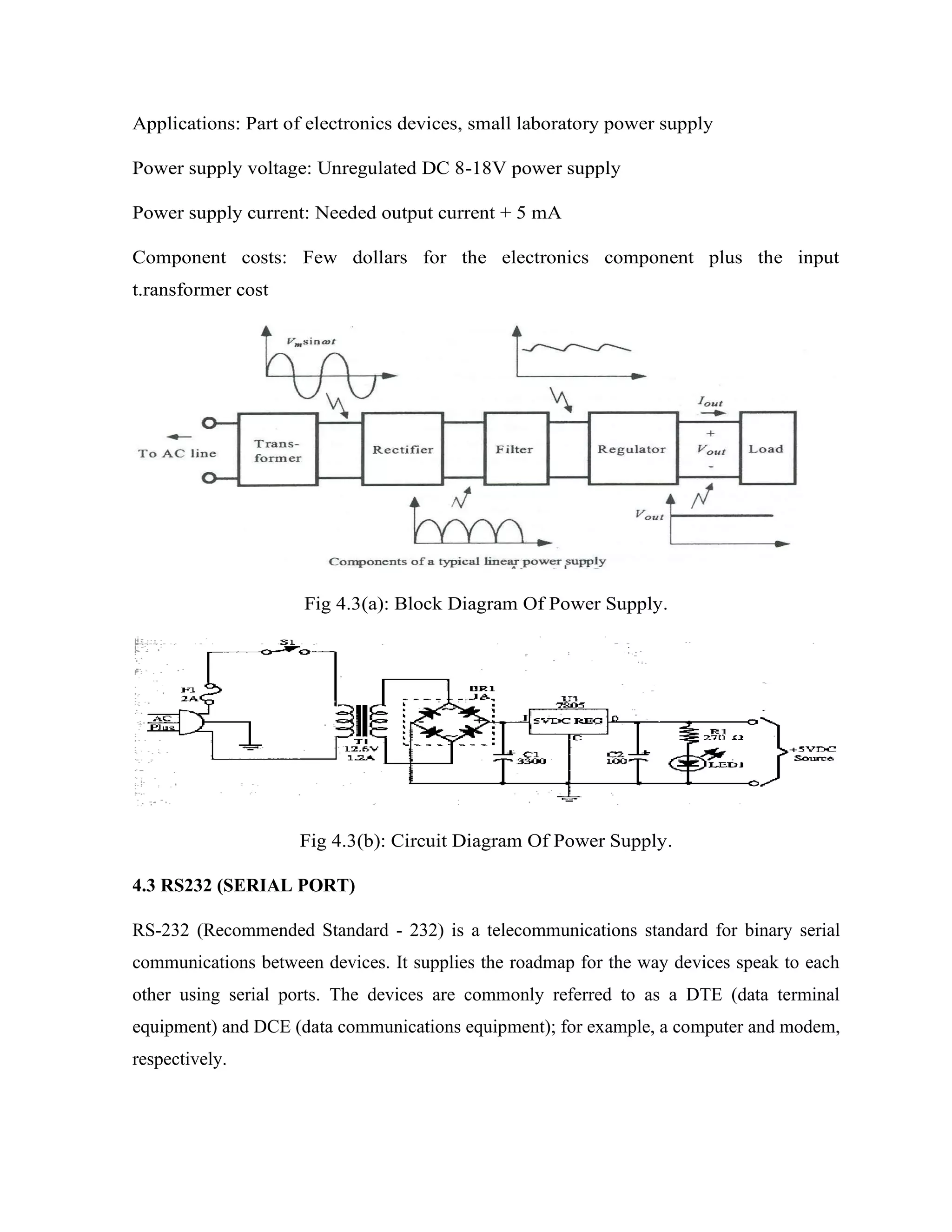
Here are the key components of a regulated power supply:
- Transformer - Steps down the high voltage mains power to a lower voltage.
- Rectifier - Converts the AC output of the transformer to DC using diodes.
- Filtering - A capacitor filters the DC output to smooth the voltage.
- Regulator - A voltage regulator IC like the 7805 regulates the filtered DC voltage to a constant value, in this case 5V.
- Heat sinking - The regulator needs to be mounted to an adequate heat sink to dissipate heat from regulating the voltage.
- Input and output terminals - Allow connection of input voltage and output regulated voltage.
So in summary, a regulated power supply takes
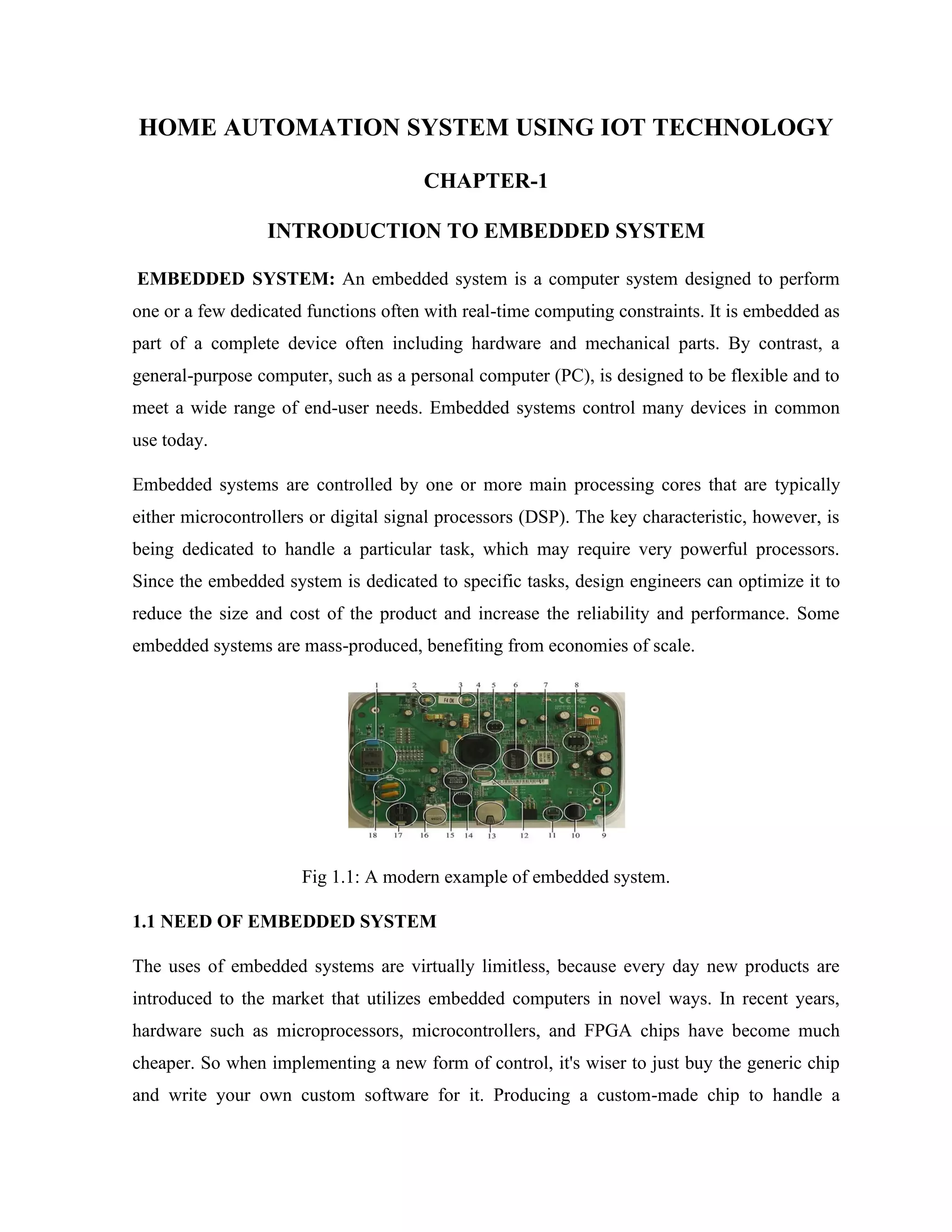
![50
#include <BlynkSimpleEsp8266.h>
char auth[] = BLYNK_AUTH_TOKEN;
char ssid[] = "ints";
char pass[] = "1234567890";
#define r1 D1
#define r2 D2
#define r3 D3
#define r4 D4
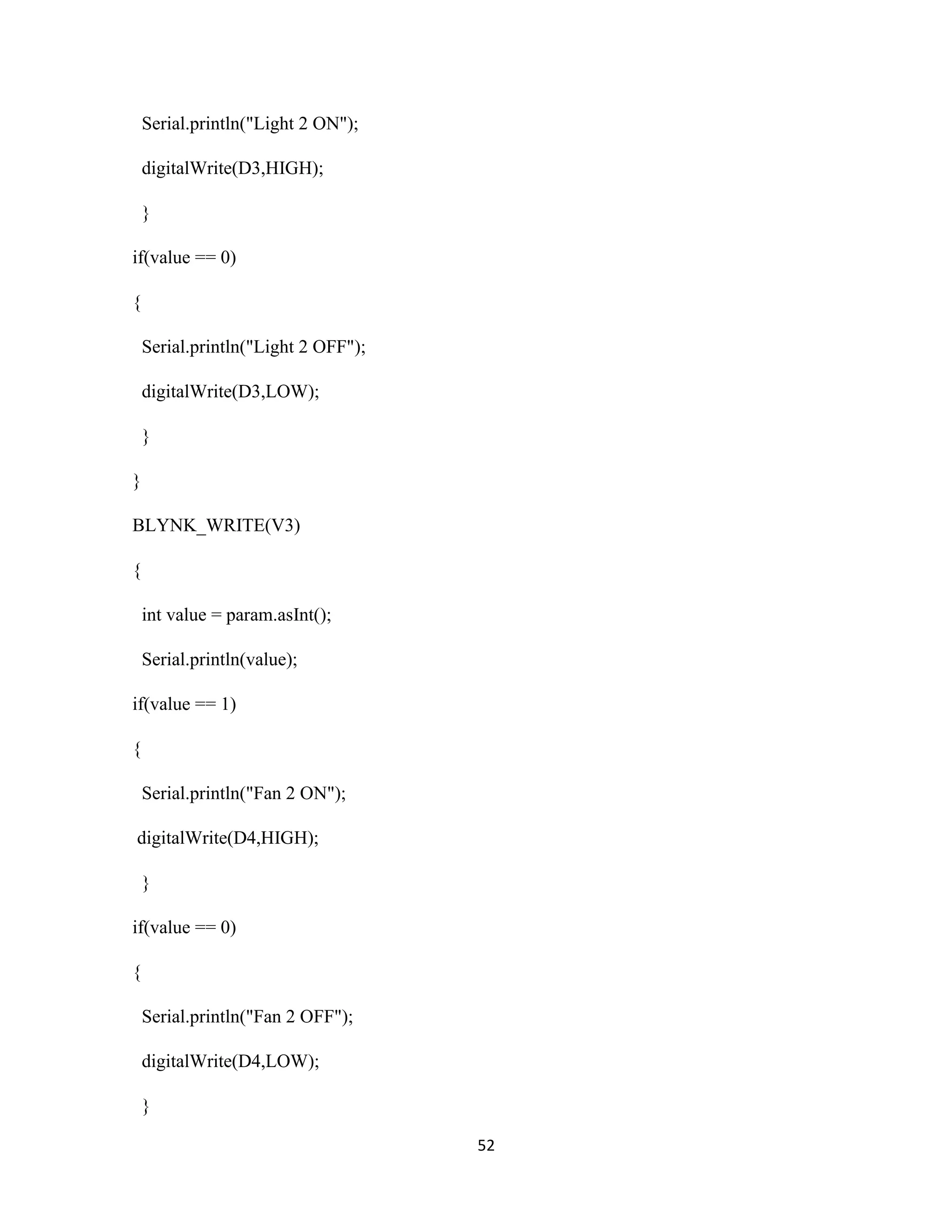
BLYNK_WRITE(V0)
{
int value = param.asInt();
Serial.println(value);
if(value == 1)
{
Serial.println("Relay 1 ON");
digitalWrite(D1,HIGH);
}
if(value == 0)
{
Serial.println("Realy 1 OFF");
digitalWrite(D1,LOW);](https://image.slidesharecdn.com/homeautomationsystemusingiottechnology-230504084904-1e4a1d58/75/HOME-AUTOMATION-SYSTEM-USING-IOT-TECHNOLOGY-pdf-50-2048.jpg)
![57
Reference
[1]. Jianjun Lv, Zhishu Li, Mingyi Mao. "A new USB home appliances based on PC and
infrared remote control protocol".2010 International Conferences on Computer and
Communication Technologies in Agriculture Engineering.2010, pp.572 -575.
[2]. Shengwen Chen, Chunghuang Yang, Chung-Huang Yang.“Design and Implementation of
Live SD Acquisition Tool in Android Smart Phone". 2011 Fifth International Conference on
Genetic and Evolutionary Computing. 2011, pp. 157-162.
[3]. Xiao Yuan, Yuliang Pan, Zaiying Ling. "The Application of Infrared Remote Controlled
Code Lock in the Management of Industrial Machine Parameters” .Electrical and Control
Engineering (ICECE), 2011 International Conference on.2011, pp. 418-421.
[4]. Feng Xun, Ye Zhi-xia."Sunplus SPCE061A MCU Simulation PT2262 Coding". Journal
of Yunnan Normal University (Natural Sciences Edition), 2010. 30(4) . pp. 40-42.
[5]. Ki-Cheol Son, Jong-Yeol Lee. "The methods of android application speed up by using
NDK". Awareness Science and Technology (iCAST), 2011 3rd International Conference on.
Sept 2011, pp.382- 385.](https://image.slidesharecdn.com/homeautomationsystemusingiottechnology-230504084904-1e4a1d58/75/HOME-AUTOMATION-SYSTEM-USING-IOT-TECHNOLOGY-pdf-57-2048.jpg)