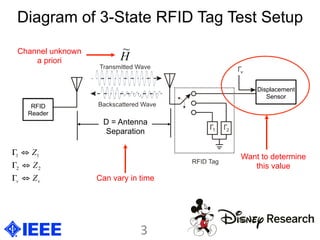
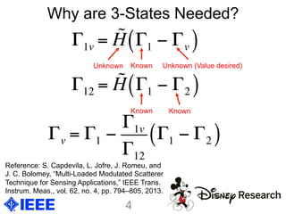
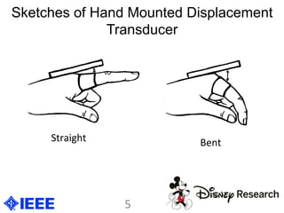
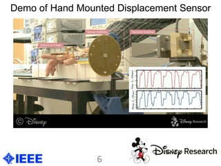
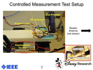
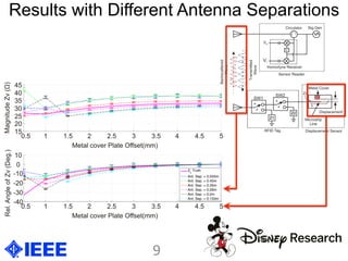
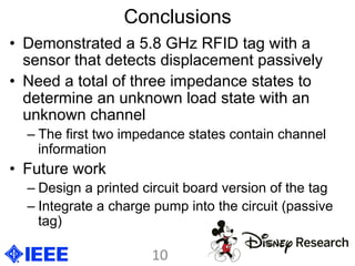
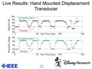
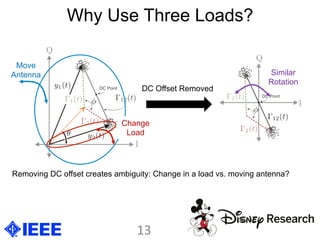
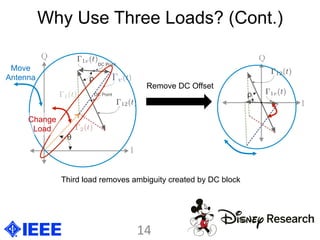
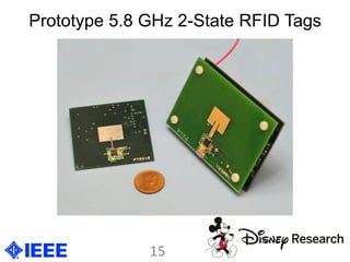
Passive Displacement Sensing using
Backscatter RFID with Multiple Loads
Jonathan Becker, Carnegie Mellon University
Joshua Griffin, Disney Research
Matthew Trotter, Disney Research
Goal	
  
Wirelessly	
  sense	
  the	
  bend	
  or	
  displacement	
  of	
  an	
  
object	
  with	
  a	
  low	
  cost	
  passive	
  device.	
  
Prior	
  Approaches	
  
•  Piezoresis:ve	
  materials	
  
•  Fiber	
  op:cs	
  
Problem	
  with	
  Prior	
  Approaches	
  
May	
  require	
  analog-­‐to-­‐digital	
  converters	
  and	
  
transmiAng	
  circuitry	
  to	
  sense	
  bend	
  –	
  rela:vely	
  
high	
  power	
  consump:on	
  
Key	
  Insight	
  
Use	
  a	
  displacement	
  sensor	
  aDached	
  to	
  hand	
  to	
  
change	
  scaDering	
  proper:es	
  of	
  a	
  backscaDer	
  
RFID	
  tag	
  as	
  the	
  hand	
  bends	
  and	
  straightens.	
  
Applica8ons	
  
•  Gestural	
  interfaces	
  
•  Virtual	
  Reality	
  
•  Mo4on	
  capture	
  
2	
  
For example, see:
•  Olson et. al., “Piezoresistive strain gauges for
use in wireless component monitoring systems”
in 2008 IEEE Sensors Applications Symposium
•  Jahed et. at., “Enhanced resolution fiber optic
strain sensor based on mach-zehnder
interferometer and displacement sensing
principles” in IEEE ELECO 2009
Diagram of 3-State RFID Tag Test Setup
Want to determine
this value
D = Antenna
Separation
Can vary in time
H
~Channel unknown
a priori
vv Z
Z
Z
⇔Γ
⇔Γ
⇔Γ
22
11
3	
  
Displacement
Sensor
RFID
Reader
Why are 3-States Needed?
Γ1v = H Γ1 − Γv( )
Γ12 = H Γ1 − Γ2( )
Γv = Γ1 −
Γ1v
Γ12
Γ1 − Γ2( )
Known
Known Known
Unknown (Value desired)Unknown
4	
  
Reference: S. Capdevila, L. Jofre, J. Romeu, and
J. C. Bolomey, “Multi-Loaded Modulated Scatterer
Technique for Sensing Applications,” IEEE Trans.
Instrum. Meas., vol. 62, no. 4, pp. 794–805, 2013.
Sketches of Hand Mounted Displacement
Transducer
Straight	
  
Bent	
  
5	
  
Demo of Hand Mounted Displacement Sensor
6	
  
Fig. 4 from Paper:
Sensor in Test Setup
Covered Microstrip Displacement Sensor
for Precision Measurements
7	
  
Sensor Parts Side by Side
Controlled Measurement Test Setup
Displacement
Sensor
RF Switches
Known Loads
Tag Antenna
Reader
Antenna
(not shown)
8	
  
Results with Different Antenna Separations
9	
  
Conclusions
•  Demonstrated a 5.8 GHz RFID tag with a
sensor that detects displacement passively
•  Need a total of three impedance states to
determine an unknown load state with an
unknown channel
– The first two impedance states contain channel
information
•  Future work
– Design a printed circuit board version of the tag
– Integrate a charge pump into the circuit (passive
tag)
10	
  
Thank you!
Any questions?
11	
  
Live Results: Hand Mounted Displacement
Transducer
12	
  
Why Use Three Loads?
Removing DC offset creates ambiguity: Change in a load vs. moving antenna?
DC Offset Removed
Move
Antenna
Change
Load
Similar
Rotation
13	
  
Why Use Three Loads? (Cont.)
Move
Antenna
Remove DC Offset
Change
Load
Third load removes ambiguity created by DC block
14	
  
Prototype 5.8 GHz 2-State RFID Tags
15	
  

Passive Displacement Sensing Using Backscatter RFID with Multiple Loads

  • 1.
    Passive Displacement Sensingusing Backscatter RFID with Multiple Loads Jonathan Becker, Carnegie Mellon University Joshua Griffin, Disney Research Matthew Trotter, Disney Research
  • 2.
    Goal   Wirelessly  sense  the  bend  or  displacement  of  an   object  with  a  low  cost  passive  device.   Prior  Approaches   •  Piezoresis:ve  materials   •  Fiber  op:cs   Problem  with  Prior  Approaches   May  require  analog-­‐to-­‐digital  converters  and   transmiAng  circuitry  to  sense  bend  –  rela:vely   high  power  consump:on   Key  Insight   Use  a  displacement  sensor  aDached  to  hand  to   change  scaDering  proper:es  of  a  backscaDer   RFID  tag  as  the  hand  bends  and  straightens.   Applica8ons   •  Gestural  interfaces   •  Virtual  Reality   •  Mo4on  capture   2   For example, see: •  Olson et. al., “Piezoresistive strain gauges for use in wireless component monitoring systems” in 2008 IEEE Sensors Applications Symposium •  Jahed et. at., “Enhanced resolution fiber optic strain sensor based on mach-zehnder interferometer and displacement sensing principles” in IEEE ELECO 2009
  • 3.
    Diagram of 3-StateRFID Tag Test Setup Want to determine this value D = Antenna Separation Can vary in time H ~Channel unknown a priori vv Z Z Z ⇔Γ ⇔Γ ⇔Γ 22 11 3   Displacement Sensor RFID Reader
  • 4.
    Why are 3-StatesNeeded? Γ1v = H Γ1 − Γv( ) Γ12 = H Γ1 − Γ2( ) Γv = Γ1 − Γ1v Γ12 Γ1 − Γ2( ) Known Known Known Unknown (Value desired)Unknown 4   Reference: S. Capdevila, L. Jofre, J. Romeu, and J. C. Bolomey, “Multi-Loaded Modulated Scatterer Technique for Sensing Applications,” IEEE Trans. Instrum. Meas., vol. 62, no. 4, pp. 794–805, 2013.
  • 5.
    Sketches of HandMounted Displacement Transducer Straight   Bent   5  
  • 6.
    Demo of HandMounted Displacement Sensor 6  
  • 7.
    Fig. 4 fromPaper: Sensor in Test Setup Covered Microstrip Displacement Sensor for Precision Measurements 7   Sensor Parts Side by Side
  • 8.
    Controlled Measurement TestSetup Displacement Sensor RF Switches Known Loads Tag Antenna Reader Antenna (not shown) 8  
  • 9.
    Results with DifferentAntenna Separations 9  
  • 10.
    Conclusions •  Demonstrated a5.8 GHz RFID tag with a sensor that detects displacement passively •  Need a total of three impedance states to determine an unknown load state with an unknown channel – The first two impedance states contain channel information •  Future work – Design a printed circuit board version of the tag – Integrate a charge pump into the circuit (passive tag) 10  
  • 11.
  • 12.
    Live Results: HandMounted Displacement Transducer 12  
  • 13.
    Why Use ThreeLoads? Removing DC offset creates ambiguity: Change in a load vs. moving antenna? DC Offset Removed Move Antenna Change Load Similar Rotation 13  
  • 14.
    Why Use ThreeLoads? (Cont.) Move Antenna Remove DC Offset Change Load Third load removes ambiguity created by DC block 14  
  • 15.
    Prototype 5.8 GHz2-State RFID Tags 15