Kotlin Multiplatform & Compose Multiplatform - Starter kit for pragmatics
unit-i.pdf
1. 1
Computer Organization(PC 402 CS)
Lecture notes
Unit-1
Syllabus
Basic Structure of Computers: Computer Types, Functional Units, Basic Operational Concepts, Bus
Structures, Performance, Multiprocessors and Multi-computers, Historical perspective.
Input/output Organization: Accessing I/O devices Interrupts, Processor examples, Direct memory
access, Parallel interface and serial interfacing.
Course Outcome:
CO 1: Understand the functional units and architecture of a modern computer, and interconnectivity of
I/O units using Bus structures.
Lecture Notes
1.1 Computer Types
Digital Computer: It is a fast electronic calculating machine that accepts digitized input information,
processes it according to a list of internally stored instructions and produces the resulting output
information. The list of instructions are called computer program and the internal storage is called computer
memory.
Many types of computers exist that widely differ in size, cost, computational power.
Computer types are:
Personal computer: This type of computers are most commonly used in homes, schools, business
office. They have a processing and storage unit, visual display and audio output unit and a keyboard.
Portable notebook computers: It is a compact version of personal computer with all the components
packaged into a single unit the size of a thin briefcase.
Workstations: This type of computer has high-resolution graphics input/output capability, have
significantly more computational power than personal computers. These are often used for engineering
applications, especially for interactive design work.
Mainframes/Enterprise systems/Servers: These are used for business data processing in medium to
large corporations that require much more computing power and storage capacity.
Supercomputers: These are used for the large-scale numerical calculations required in applications
such as weather forecasting and aircraft design and simulation. The size of the functional units is very
large.
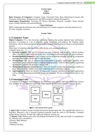
1.2 Functional Units
A computer in its simplest form comprises five functional units namely input unit, output unit memory
unit, arithmetic & logic unit and control unit. Figure depicts the functional units of a computer system.
1. Input Unit: Computer accepts encoded information through input unit. The standard input device is a
keyboard. Whenever a key is pressed, keyboard controller sends the code to CPU/Memory. Examples
include Mouse, Joystick, Tracker ball, Light pen, Digitizer, Scanner etc.
2. Memory Unit: Memory unit stores the program instructions (Code), data and results of computations
etc. Memory unit is classified as:
• Primary /Main Memory
• Secondary
• Memory/Auxiliary
2. 2
Computer Organization(PC 402 CS)
Primary memory is a semiconductor memory that provides access at high speed. Run time program
instructions and operands are stored in the main memory. Main memory is classified again as ROM and
RAM. ROM holds system programs and firmware routines such as BIOS, POST, I/O Drivers that are
essential to manage the hardware of a computer. RAM is termed as Read/Write memory or user memory
that holds run time program instruction and data. While primary storage is essential, it is volatile in nature
and expensive. Additional requirement of memory could be supplied as auxiliary memory at cheaper cost.
Secondary memories are non volatile in nature.
3. Arithmetic and logic unit: ALU consist of necessary logic circuits like adder, comparator etc., to
perform operations of addition, multiplication, comparison of two numbers etc.
4. Output Unit: Computer after computation returns the computed results, error messages, etc. via output
unit. The standard output device is a video monitor, LCD/TFT monitor. Other output devices are printers,
plotters etc.
5. Control Unit: Control unit co-ordinates activities of all units by issuing control signals. Control signals
issued by control unit govern the data transfers and then appropriate operations take place. Control unit
interprets or decides the operation/action to be performed.
The operations of a computer can be summarized as follows:
1. A set of instructions called a program reside in the main memory of computer.
2. The CPU fetches those instructions sequentially one-by-one from the main memory, decodes them and
performs the specified operation on associated data operands in ALU.
3. Processed data and results will be displayed on an output unit.
4. All activities pertaining to processing and data movement inside the computer machine are governed by
control unit
1.3 Basic Operational Concepts
An Instruction consists of two parts, an Operation code and operand/s as shown below:
Let us see a typical instruction
ADD LOCA, R0
This instruction is an addition operation.
The following are the steps to execute the instruction:
Step 1: Fetch the instruction from main memory into the processor
Step 2: Fetch the operand at location LOCA from main memory into the processor
Step 3: Add the memory operand (i.e. fetched contents of LOCA) to the contents of register R0
Step 4: Store the result (sum) in R0.
The same instruction can be realized using two instructions as
Load LOCA, R1
Add R1, R0
The steps to execute the instructions can be enumerated as below:
Step 1: Fetch the instruction from main memory into the processor
Step 2: Fetch the operand at location LOCA from main memory into the processor Register R1
Step 3: Add the content of Register R1 and the contents of register R0
Step 4: Store the result (sum) in R0
3. 3
Computer Organization(PC 402 CS)
The above diagram shows the ALU and control circuitry. The processor contains a number of registers used
for several different purpose. The registers are:
Program Counter(PC): It contains the memory address of the next instructions to be fetched and
executed.
Memory Address Registers(MAR): It holds the address of the location to be accessed.
Memory Data Registers(MDR): It holds the data to be written into or read out of the addressed
location.
Instruction Register(IR): It holds the instruction that is currently being executed.
General purpose registers: These are the registers ranging from R0 through Rn-1 which are used
for intermediatory communication.
Let us see the typical operating steps:
1. Program resides in the memory which is brought from the input devices.
2. Execution starts by updating the PC with first instructions address.
3. Contents of PC are transferred to MAR, where MAR will locate the instruction in the memory.
4. The instruction is transferred to MDR, and from MDR to IR and then to ALU for the
processing.
5. ALU performs the desired operation and send the result to MDR and that output is either
transferred to output devices or to memory by specifying the address in MAR.
1.4 Bus Structure
A group of lines that serves as a connecting path for several devices is called bus. The lines carry the data,
address and control information. Simplest way to connect the functional units is by single bus.
All the units are connected to the bus. The bus can be used for only one transfer at a time, only two units
can actively use the bus at any given time. The main advantage of the single bus structure is its low cost
and its flexibility for attaching peripheral devices. The devices connected to a bus widely vary in their speed
of operation. Devices like keyboard and printers are relatively slow. Devices like magnetic or optical disks
are fast. To maintain the speed difference between the devices we use buffer registers to hold the
information during transfers.
1.5 Performance
4. 4
Computer Organization(PC 402 CS)
The performance of the computer depends on many features like clock, speed, instruction set, compiler
etc…
The most important measure of the performance of the computer is how quickly it can execute programs.
The speed with which a computer execute programs is affected by the design of its hardware and its machine
language instructions. For, best performance it is necessary to design the compiler, the machine instruction
set , and the hardware in a coordinated way. To speed up the operations cache memory is also used.
1. Processor clock: The clock defines regular time intervals, called clock cycles. To execute a
machine instruction, the processor divides the action to be performed into a sequence of basic steps,
such that each step can be completed in one clock cycle.
Clock rate, R=1/P cycles per second, where P is one clock cycle.
Processors used in personal computes have clock rate from a few hundreds million to over a billion
cycles per sec. cycles per second are called Hertzs.
2. Basic performance equation:
Basic Performance Equation is T=N*S/R where
T= Processor time
N=number of machine language instructions
S=average number of basic steps to execute a machine instruction.
R=Clock rate (cycles per second).
To achieve high performance, the computer designer must seek ways to reduce the value of T,
which means reducing N,S and increasing R.
3. Pipelining and Superscalar:
An improvement in the performance can be achieved by overlapping the execution of successive
instructions, using a technique called pipelining.
Consider the instruction
ADD R1,R2,R3
which adds the contents of registers R1,R2 and places the sum in R3. The contents of R1 and R2
are first transferred to the inputs of the ALU. After the add operation is performed, the sum is
transferred to R3. The processor can read the next instruction from the memory while the addition
operation is being performed. Pipelining increases the rate of executing instructions significantly
and causes the effective value of S to reduce. With such an arrangement, it becomes possible to
start the execution of several instructions in every clock cycle. This mode of operation is called
superscalar execution.
4. Instruction set(RISC and CISC):
There are two types of instruction sets.They are:
1. RISC(Reduced Instruction Set Computers): The main idea behind this is to make hardware
simpler by using an instruction set composed of a few basic steps for loading, evaluating, and
storing operations just like a load command will load data, a store command will store the data.
Characteristic of RISC –
Simpler instruction, hence simple instruction decoding.
Instruction comes undersize of one word.
Instruction takes a single clock cycle to get executed.
More general-purpose registers.
Simple Addressing Modes.
Fewer Data types.
A pipeline can be achieved.
5. 5
Computer Organization(PC 402 CS)
2. CISC(Complex Instruction Set Computers): The main idea is that a single instruction will
do all loading, evaluating, and storing operations just like a multiplication command will do
stuff like loading data, evaluating, and storing it, hence it’s complex.
Characteristic of CISC –
Complex instruction, hence complex instruction decoding.
Instructions are larger than one-word size.
Instruction may take more than a single clock cycle to get executed.
Less number of general-purpose registers as operations get performed in memory itself.
Complex Addressing Modes.
More Data types.
5. Performance Measurement:
System Performance Evaluation Corporation(SPEC) is a nonprofitable organization which
evaluates the performance of many computers. SPEC rating is computed as follows
1.6 Multiprocessors and Multicomputers
Multiprocessor: A Multiprocessor is a computer system with two or more central processing units (CPUs)
share full access to a common RAM. The main objective of using a multiprocessor is to boost the system’s
execution speed, with other objectives being fault tolerance and application matching.
Multicomputer: A multicomputer system is a computer system with multiple processors that are
connected together to solve a problem. Each processor has its own memory and it is accessible by that
particular processor and those processors can communicate with each other via an interconnection network.
Difference between multiprocessor and Multicomputer:
1. Multiprocessor is a system with two or more central processing units (CPUs) that is capable
of performing multiple tasks where as a multicomputer is a system with multiple processors
that are attached via an interconnection network to perform a computation task.
2. A multiprocessor system is a single computer that operates with multiple CPUs where as a
multicomputer system is a cluster of computers that operate as a singular computer.
3. Construction of multicomputer is easier and cost effective than a multiprocessor.
4. In multiprocessor system, program tends to be easier where as in multicomputer system,
program tends to be more difficult.
5. Multiprocessor supports parallel computing, Multicomputer supports distributed computing.
1.7 Historical Perspective
We have five generations of computers.
First Generation: The key concept of stored program was introduced by John von Neumann. Programs
and their data were located in the same memory, as they are today. Assembly language was used to prepare
programs and was translated into machine language for execution. Basic arithmetic operations were
performed in a few milliseconds using vacuum tube s technology to implement logic functions.
Second Generation:
Transistors were invented in 1940 and they replaced the vacuum tubes. Magnetic core memories, magnetic
drum storage devices, compilers, I/O Processors were major contributions in this generation.
Third Generation: In this generation Integrated circuits(IC) came up where fabrication of many transistors
on a single silicon chip began. IC’s enabled lower-cost and faster processors and memory elements to be
built. Integrated-circuit memories began to replace magnetic core memories. This generation also included
introduction of of microprogramming, parallelism and pipelining. Cache and virtual memories were
developed.
6. 6
Computer Organization(PC 402 CS)
Fourth Generation: In this generation integrated-circuit fabrication techniques had evolved to the point
where complete processors and large section of the main memory of small computers could be implemented
on single chip. Tens of thousands of transistors could be placed on a single chip, and the name Very Large
Scale Integration(VLSI) was coined to describe this technology. Portable computers, desktops personal
computers and workstations, interconnected by local area networks and the Internet have become the
dominant mode of computing.
Beyond fourth Generation: Computers featuring artificial intelligence, massively parallel machines,
extensive distributed systems are the examples of current trends. The growth of computer industry is fueled
by increasingly powerful and affordable desktop computers and widespread use of the vast information
resources on the internet.
The development in technology have been many innovations in the architecture of computers such as the
use of caches and pipelining which have had s significant impact on computer performance.
Input/Output Organization
1.2.1 Accessing I/O Devices:
Most modern computers use single bus arrangement for connecting I/O devices to CPU &
Memory
The bus enables all the devices connected to it to exchange information
Bus consists of 3 set of lines : Address, Data, Control
Processor places a particular address (unique for an I/O Dev.) on address lines
Device which recognizes this address responds to the commands issued on the Control lines
Processor requests for either Read / Write
The data will be placed on Data lines
Hardware to connect I/O devices to bus:
Interface Circuit
– Address Decoder
– Control Circuits
– Data registers
– Status registers
The Registers in I/O Interface – buffer and control
Flags in Status Registers like SIN SOUT
Data Registers, like Data-IN, Data-OUT
I/O Interface for an input device
Memory mapped I/O
I/O devices and the memory share the same address space , the arrangement is called Memory-
mapped I/O.
In Memory -mapped I/O portions of address space are assigned to I/O devices and reads and
writes to those addresses are interpreted as commands to the I/O device.
“DATAIN” is the address of the input buffer associated with the keyboard.
- Move DATAIN, R0 reads the data from DATAIN and stores them into processor register R0;
7. 7
Computer Organization(PC 402 CS)
- Move R0, DATAOUT sends the contents of register R0 to location DATAOUT
Option of special I/O address space or incorporate as a part of memory address space (address
bus is same always).
When the processor places the address and data on the memory bus, the memory system ignores
the operation because the address indicates a portion of the memory space used for I/O.
The device controller, however, sees the operation, records the data, and transmits it to the device
as a command.
User programs are prevented from issuing / I /O operations directly because the OS does not
provide access to the address space assigned to the I/O devices and thus the addresses are
protected by the address translation.
Memory mapped I/O can also be used to transmit data by writing or reading to select addresses.
The device uses the address to determine the type of command, and the data may be provided by
a write or obtained by a read.
A program request usually requires several separate I/O operations. Furthermore, the processor
may have to interrogate the status of the device between individual commands to determine
whether the command completed successfully.
Registers in keyboard and display interfaces
Registers: DATAIN, DATAOUT, STATUS, CONTROL
Flags: SIN, SOUT - Provides status information for keyboard and display unit
KIRQ, DIRQ – Keyboard, Display Interrupt request bits
DEN, KEN –Keyboard, Display Enable bits
Data transfer between the central computer to I/O devices may be handled in variety of modes.
–Programmed I/O
–Interrupt Initiated I/O
–Direct Memory Access (DMA)
Programmed I/O:
In this case, use dedicated I/O instructions in the processor. These I/O instructions can specify
both the device number and the command word.
The process of periodically checking status bits to see if it is time for the next I/O operation, is
called polling. Polling is the simplest way for an I/O device to communicate with the processor
the processor.
The I/O device simply puts the information in a Status register, and the processor must come and
get the information. The processor is totally in control and does all the work.
Interrupt Initiated I/O
Interrupt -driven I/O employs I/O interrupts to driven I/O , employs I/O interrupts to indicate to
the processor that an I/O device needs attention.
8. 8
Computer Organization(PC 402 CS)
When a device wants to notify the processor that it has completed some operation or needs
attention, it causes the processor to be interrupted
Direct Memory Access (DMA):
Although a DMA controller transfers data without intervention by the processor, its operation
must be under the control of a program executed by the processor, usually an operating system
routine.
To initiate the transfer of a block of words, the processor sends to the DMA controller the starting
address, the number of words in the block, and the direction of the transfer. The DMA controller
then proceeds to perform the requested operation.
1.2.2 Interrupts:
Whenever any wait instruction is executed the the processor is not performing any task.
In the meanwhile the processor can perform many other tasks than waiting for the I/O devices to
get ready.
To do this we can arrange an alert for the I/O Device to inform processor that it is ready.
For this a bus control line called interrupt- request line is arranged.
The routine executed in the response to interrupt- request line is called Interrupt service
routine(IRS).
All the registers, flags, program counter values are saved by the processor before running ISR.
From the above fig, the processor first completes execution of instruction i and then loads the first
instruction address of the ISR .After execution of ISR the processor should return back to i+1 instruction.
interrupt-acknowledge signal - I/O device interface accomplishes this b y execution of an
instruction in the interrupt-service routine (ISR) that accesses a status or data register in the device
interface; implicitly informs the device that its interrupt request has been recognized. IRQ signal is
then removed by device.
ISR is a sub-routine – may belong to a different user than the one being executed and then halted.
The condition code flags and the contents of any registers used by both the interrupted program
and the interrupt -service routine are saved and restored.
The concept of interrupts is used in operating systems and in many control li i applications, wh if
ere processing of certain routines must be accurately timed relative to external events (e.g. real-
time processing).
i. Interrupt Hardware:
All the devices are connected to the line via switches to ground.
By default the line is equal to Vdd which is inactive state.
When a device requests an interrupt by closing a switch, the voltage on the line drop to 0 causing
interrupt-request signal INTR.
The INTR is the logical OR of the request from individual devices, that is,
9. 9
Computer Organization(PC 402 CS)
INTR=INTR1+………+INTRn
Interrupt-Request line
ii. Enabling and Disabling Interrupts:
Device activates interrupt signal line and waits with this signal activated until processors
attends.
The interrupt signal line is active during execution of ISR and till the device caused interrupt
is serviced
Necessary to ensure that the active signal does not lead to successive interruptions (level -
triggered input) causing the system to fall in infinite loop.
What if the same device interrupts again, within an ISR ?
Three methods of Controlling Interrupts (single device)
– Ignoring interrupt
– Disabling interrupts
– Special Interrupt request line
Ignoring Interrupts – Processor hardware ignores the interrupt request line until the
execution of the first instruction of the ISR completed
– Using an interrupt disable instruction after the first instruction of the ISR
– no further interrupts
– A return from interrupt instruction is completed before further interruptions can occur
Disabling Interrupts – Processor automatically disables interrupts before starting the
execution of the ISR
– The processor saves the contents of PC and PS (status (status register) before performing
interrupt disabling.
– The interrupt-enable is set to 0
– no further interrupts allowed
– When return from interrupt instruction is executed the contents of the PS are restored from
the stack, and the interrupt enable is set to 1
Special Interrupt line – Special interrupt request line for which the interrupt handling circuit
responds only to the leading edge of the signal
– Edge –triggered
– Processor receives only one request regardless of how long the line is activated
– No separate interrupt disabling instructions
The sequence of events involved in handling an interrupt request from a single device.
Assuming that interrupts are enabled, the following is a typical scenario:
1. The device raises an interrupt request.
2. The processor interrupts the program currently being executed.
3. Interrupts are disabled by changing the control bits in the PS (except in the case of edge -triggered
interrupts) executed. PS (except in the case of edge -triggered interrupts).
4. The device is informed that its request has been recognized, and in response, and in response, it
deactivates the interrupt - request signal.
10. 10
Computer Organization(PC 402 CS)
5. The action requested by the interrupt is performed by the interrupt-service routine.
6. Interrupts are enabled and execution of the interrupted program is resumed.
Handling Multiple Devices
Multiple devices can initiate interrupts
They uses the common interrupt request line
Techniques are
– Polling
– Vectored Interrupts
– Interrupt Nesting
– Daisy Chaining
- Polling:
The IRQ (interrupt request) bit in the status register is set when a device is requesting an
interrupt.
The Interrupt service routine polls the I/O devices connected to the bus.
The first device encountered with the IRQ bit set is serviced and the subroutine is invoked.
Easy to implement, but too much time spent on checking the IRQ bits of all devices, though
some devices may not be requesting service.
- Vectored Interrupts:
Device requesting an interrupt identifies itself directly to the processor
The device sends a special code to the processor over the bus.
The code contains the
– identification of the device
– starting address for the ISR
– address of the branch to the ISR
PC finds the IS R address from the code.
To add flexibility for multiple devices - corresponding ISR is executed by the processor
using a branch address to the appropriate routine - device specified Interrupt Vector.
An interrupt vector is the memory address of an interrupt handler, or an index into an array
called an interrupt vector table or dispatch table - a table of interrupt vectors (pointers to
routines that handle interrupts).
- Interrupt Nesting :
Pre -Emption of low priority Interrupt by another high priority interrupt is known as
Interrupt nesting.
Disabling Interrupts during the execution of the ISR may not favour devices which need
immediate attention.
Need a priority of IRQ devices and accepting IRQ from a high priority device. • The
priority level of the processor can be changed dynamically.
Organizing I /O devices in a prioritized structure.
Each of the interrupt-request lines is assigned a different priority level.
The processor is interrupted only by a high priority device
- Daisy Chaining:
The interrupt request line INTR is common to all the devices
11. 11
Computer Organization(PC 402 CS)
The interrupt acknowledgement line INTA is connected to devices in a DAISY CHAIN
way
INTA propagates serially through the devices
Device that is electrically closest to the processor gets high priority
Low priority device may have a danger of STARVATION
Combining Daisy chaining and Interrupt nesting to form priority group. Each group has
different priority levels and within each group devices are connected in daisy chain way
1.2.3 Processor Examples:
ARM Interrupt Structure:
ARM processor has a simple yet powerful exception-handling mechanism.
There are 5 sources for exception, only two of them are external interrupt-request ie..
IRQ,FIQ(Fast Interrupt Request).
Exceptions are handled according to the following priority structure:
1. Reset(highest priority): This exception will override all other conditions to bring
the processor to a known starting condition.
2. Data abort: This rises when there is error in reading and writing data
3. FIQ
4. IRQ
5. Prefetch abort: This arises when an error occurs during prefetching the instruction
from the memory
6. Undefined instruction(lowest priority)
The lower-order byte of CPSR(Current Program Status Register) is given which has 2
interrupt mask bits, one each for IRQ and FIQ and 5 modes bits M4-M0 which indicates the
mode in which the processor is running.
There are 6 modes, one mode is User mode and 5 privileged modes for each type of
exception.
12. 12
Computer Organization(PC 402 CS)
When the processor switches to a different mode, it also switches some of the registers
accessible to the program.
The register set accessible in each mode is Registers R0 to R7,CPSR.
In privileged modes, except FIQ, registers R8 to R12 are also accessible.
When the processor accepts an interrupt, it takes the following actions:
1. It saves the returned address of the interrupted program in register 14 of the corresponding
modes. For example, in the case of FIQ, it saves in R14 fiq.
2. It saves the contents of the processor status register, CPSR, in the corresponding SPSR.
3. It changes the mode bits in CPSR according to the type of interrupt.
4. It branches to the interrupt-service routine starting at the appropriate vector address.
1.2.4 Direct Memory Access (DMA):
For I/O transfer, Processor determines the status of I/O devices, by – Polling – Waiting for
Interrupt signal
Considerable overhead is incurred in above I/O transfer processing
To transfer large blocks of data at high Speed, between EXTERNAL devices & Main
Memory, DMA approach is often used
DMA controller allows data transfer directly between I/O device an d Memory, with minimal
intervention of processor.
DMA controller acts as a Processor, but it is controlled by CPU
13. 13
Computer Organization(PC 402 CS)
To initiate transfer of a block of words, the processor sends the following data to controller
– The starting address of the memory block
– The word count
– Control to specify the mode of transfer such as read or write
– A control to start the DMA transfer
DMA controller performs the requested I/O operation and sends a interrupt to the processor
upon completion.
Registers in DMA
Use of DMA Controller in a computer system
In DMA interface
First register stores the starting address
Second register stores Word count
Third register contains status and control flags
Memory accesses by the processor and DMA Controller are interwoven
DMA devices have higher priority then processor over BUS control
Cycle Stealing:- DMA Controller “steals” memory cycles from processor, though processor
originates most memory access.
Block or Burst mode:- The DMA controller may given exclusive access to the main
memory to transfer a block of data without interruption
Conflicts in DMA:
- Processor and DMA,
- Two DMA controllers, try to use the Bus at the same time to access the main memory.
Bus Arbitration:
Bus master: device that initiates data transfers on the bus.
The next device can take control of the bus after the current master relinquishes control
Bus Arbitration: process by which the next device to become master is selected
Centralized and Distributed Arbitration
14. 14
Computer Organization(PC 402 CS)
A simple arrangement for bus arbitration using a daisy chain
– BR (bus request ) line - open drain line - the signal on this line is a logical OR of the bus request from
all the DMA devices
– BG (bus grant) line - processor activates this line indicating (acknowledging) to all the DMA devices
(connected in daisy chain fashion) that the BUS may be used when its free.
– BBSY (bus busy) line - open collector line - the current bus master indicates devices that it is currently
using the bus by signalling this line.
Bus arbitrary using daisy chain
Centralized Arbitration
– Separate unit (bus arbitration circuitry) connected to the bus
– Processor is normally the bus master, unless it grants bus mastership to DMA
For the timing/control:
- DMA controller 2 requests and acquires bus mastership and later releases the bus.
- During its tenure as the bus master, it may perform one or more data transfer operations,
depending on whether it is operating in the cycle stealing or block mode.
- After it releases the bus, the processor resumes bus mastership.
Distributed Arbitration
– All devices waiting to use the bus has to carry out the arbitration process - no central arbiter
– Each device on the bus is assigned with a 4-bit identification number
– One or more devices request the bus by asserting the start-arbitration signal and place their
identification number on the four open collector lines
– ARB0 through ARB3 are the four open collector lines
– One among the four is selected using the code on the lines and one with the highest ID number
15. 15
Computer Organization(PC 402 CS)
Assume that two devices, A and B, having ID numbers 5 and 6, respectively, are requesting the
use of the bus.
Device A transmits the pattern 0101, and device B transmits the pattern 0110. The code seen by
both devices is 0111.
Each device compares the pattern on the arbitration lines to its own ID, starting from the most
significant bit.
If it detects a difference at any bit position, it disables its drivers at that bit position and for all
lower-order bits. It does so by placing a 0 at the input of these drivers does so by placing a 0 at
the input of these drivers.
In the case of our example, device A detects a difference on line ARB I. Hence, it disables its d
rivers on lines ARB 1 and ARBO. This causes the pattern on the arbitration lines to change.