Downloaded 443 times

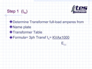

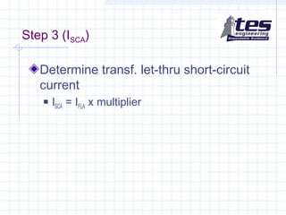
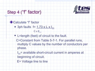
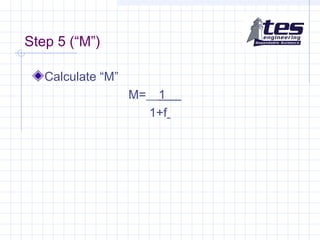
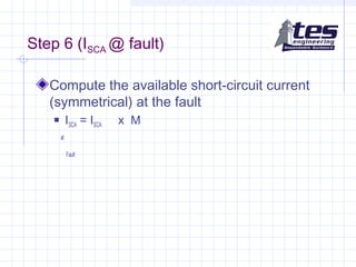
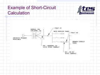
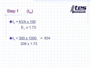
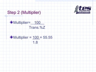
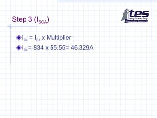
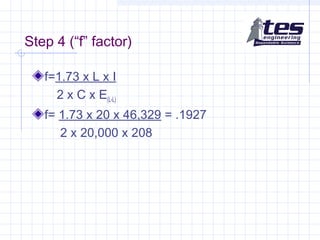
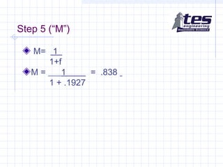
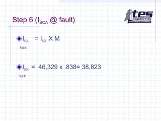
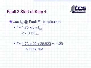
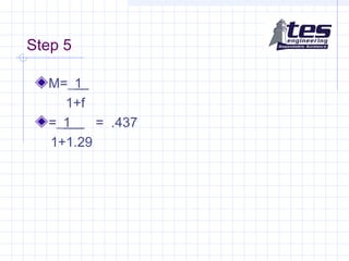
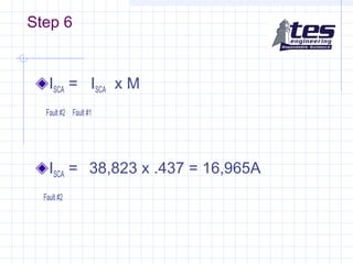


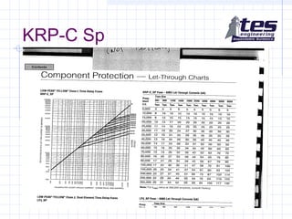


This document provides information and steps for calculating short-circuit currents using the point-to-point method. It defines key terms like interrupting capacity and discusses National Electric Code requirements. The point-to-point method calculates available short-circuit currents at various points on electrical distribution systems assuming unlimited primary current. It provides a 6 step process for determining the available short-circuit current at the fault, including calculating the transformer full load amps, multiplier, short-circuit current, "f" factor, "M" value, and final short-circuit current at the fault. An example calculation is shown. The document also discusses equipment withstand ratings and peak let-through currents.


![Short circuit followup[1]](https://cdn.slidesharecdn.com/ss_thumbnails/shortcircuitfollowup1-140206133432-phpapp01-thumbnail.jpg?width=640&height=640&fit=bounds)