4
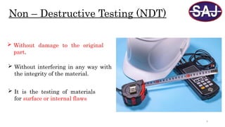
Non – DestructiveTesting (NDT)
Without damage to the original
part.
It is the testing of materials
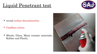
for surface or internal flaws
Without interfering in any way with
the integrity of the material.
5.
Importance Of NDT
To ensure product reliability
To prevent accidents and save human lives
To ensure customer satisfaction and to maintain the manufacturer’s “good name”
To aid in better product design
Prevent accidents and reduce costs
6.
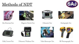
Methods of NDT
DyePenetrantTest Magnetic ParticleTest UltrasonicTest Radiography Test
Eddy Current Test Ultrasonic ThicknessTest Video BorescopicTest IRThermography Test
7.
7
Most Common NDTMethod
Visual Test
Liquid Penetrant Test
Magnetic Particle Test
Ultrasonic Test
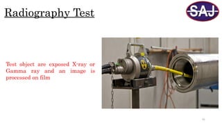
Radiography Test
8.
8
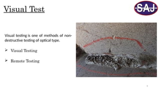
Visual Test
Visual testingis one of methods of non-
destructive testing of optical type.
Visual Testing
Remote Testing
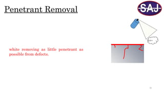
19
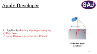
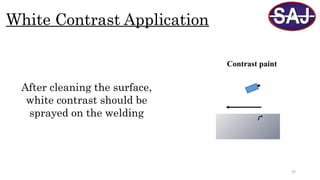
Apply Developer
Appliedby dusting, dipping or spraying.
Thin layer
Spray Distance form Surface 12 inch
Clean then apply
Developer
20.
20
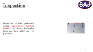
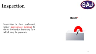
Inspection
Inspection is thenperformed
under appropriate lighting
(100lux) to detect indication
from any flaw which may be
presents.
21.
21
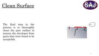
Clean Surface
The finalstep in the
process is to thoroughly
clean the part surface to
remove the developer from
parts that were found to be
acceptable.
24
Advantage of LPT
Workson complicated geometric shapes
Visual, real-world results
Sensitive to small surface interruptions
Liquid penetrant testing materials are individually very cost-
effective
Find Surface Defect
25.
25
Disadvantage of LPT
Sensitive to surface-breaking defects only
No depth sizing
Time-taking; post-cleaning also necessary
No recordable data handy for progress monitoring
26.
26
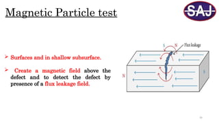
Magnetic Particle test
Surfaces and in shallow subsurface.
Create a magnetic field above the
defect and to detect the defect by
presence of a flux leakage field.
30
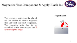
Magnetize Test Component& Apply Black Ink
Magnet & Ink
The magnetic yoke must be placed
on the surface to create magnetic
flux and black ink must be sprayed.
The magnetic yoke has to be
examined in the same way as the X
by holding the angel
33
Advantage of MPT
Can detect both surface and near-surface indications
A relatively fast method of examination.
Indications are visible directly on the surface.
Low-cost compared to many other NDE methods.
Post-cleaning generally not necessary.
34.
34
Disadvantage of MPT
Non-ferrous materials, such as aluminium, magnesium, or most
stainless steels, cannot be inspected.
Examination of large parts may require use of equipment with
special power requirements.
Only small sections or small parts can be examined at one time.
Detects surface and near-to-surface discontinuities only
35.
35
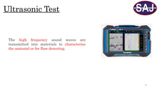
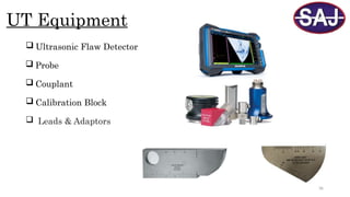
Ultrasonic Test
The highfrequency sound waves are
transmitted into materials to characterise
the material or for flaw detecting.
38
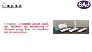
Couplant
A couplant isa material (usually liquid)
that facilitates the transmission of
ultrasonic energy from the transducer
into the test specimen.
39.
39
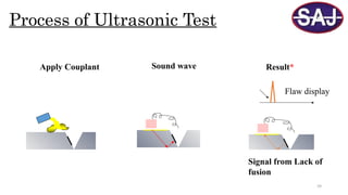
Process of UltrasonicTest
Apply Couplant Sound wave
Signal from Lack of
fusion
Flaw display
Result*
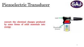
41
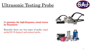
Ultrasonic Testing Probe
Itsgenerate the high-frequency sound waves
by Transducer.
Basically there are two types of probe angel
probe(30-70 degree) and normal probe
42.
42
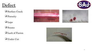
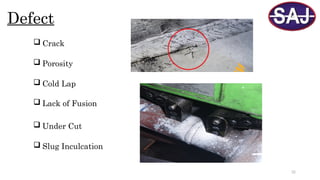
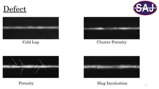
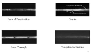
Defect
Root Crack
Lack of Side-wall fusion
Side-Wall Crack
Center Line Crack
Slug Inculcation
Lack of Penetration
Porosity
Over Penetration
43.
43
Advantage of UT
High penetration power, allowing for flaw detection deep within a part
Can be used to test when only one side of an object is accessible
Highly automated and portable operations possible
Immediate results can be obtained, allowing for immediate decisions
to be made
44.
44
Disadvantage of UT
Requires experienced technicians for inspection and for data
interpretation
Objects that are rough, irregularly shaped, very small or thin, or not
homogeneous are difficult to inspect
Couplants required for tests that use conventional UT
Loose scale or paint will need to be removed before testing can
commence, although clean, properly bonded paint can be left in place
48
Radiography Film
Radiography Filmconsists of a thin
transparent plastic sheet or base with
and emulsion of gelatin containing
with very fine grains of silver bromide
(AgBr)
50
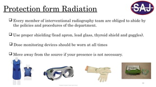
Protection form Radiation
Every member of interventional radiography team are obliged to abide by
the policies and procedures of the department.
Use proper shielding (lead apron, lead glass, thyroid shield and goggles).
Dose monitoring devices should be worn at all times
Move away from the source if your presence is not necessary.
53
Advantage of RT
Radiography can be used with most materials
Radiography can be used to provide a permanent visual record
Minimal surface preparation require
Radiography can reveal fine discontinuities within a material
54.
54
Disadvantage of RT
Radiography safety procedures must always be followed
Accessibility can be limited the radiographer must have access to both sides
of the test
Discontinuities that are not parallel with the radiation beam are difficult to
locate.
Radiography is an expensive testing method
55.
55
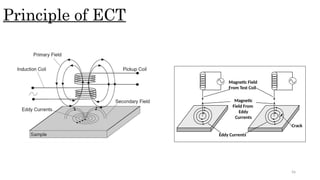
Eddy Current Test
Applicable to electrically conductive
materials only
Surface or subsurface flaws
Conductivity measurement and coating
thickness measurement.
In this method eddy currents are produced in
the product by bringing it close to an
alternating current carrying coil
57
Advantages of ECT
•Ableto detect surface and near-surface cracks as small as 0.5mm
•Provides immediate feedback
•Portable and light equipment
•Non-contact method making it possible to inspect high-temperature surfaces and
underwater surfaces
•Able to detect defects through several layers, including non-conductive surface coatings,
without interference from planar defects
58.
58
Disadvantage of ECT
•Canonly be used on conductive materials
•The depth of penetration is variable
•Very susceptible to magnetic permeability changes – making testing of welds in ferromagnetic
materials difficult – but with modern digital flaw detectors and probe design, not impossible
•Unable to detect defects that are parallel to the test object’s surface
•Careful signal interpretation is required to differentiate between relevant and non-
relevant indications