The document discusses procedures for charging blastholes, including loading explosives into blastholes. There are two main methods discussed: column loading and deck loading.
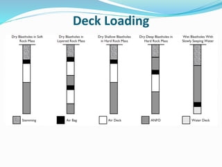
Column loading involves loading a continuous column of explosive from the bottom to the top of the blasthole. Deck loading involves alternating layers of explosive and stemming material throughout the blasthole, resulting in a smaller total amount of explosive.
Deck loading is preferred for deeper blastholes or to address issues like controlling vibrations and fragmentation. However, it requires more labor and initiation materials compared to column loading. Proper priming and initiation procedures are also discussed to ensure effective detonation of the explosive column.
my presentation about kick tolerance and contain 3 videos
the reference (well drilling & construction) Hussain Rabia
and weatherford essay & videos from youtube
Sheet1Moisture content analysis final resultsGroupValue of m3 (g)A.docxbjohn46
Sheet1Moisture content analysis final resultsGroupValue of m3 (g)A21.459B25 kPa34.35950 kPa18.771C19.282D17.816E23.651F26.148GTBCH28.664
LEEDS BECKETT UNIVERSITY
CIVIL ENGINEERING
GEOTECHNICAL ENGINEERING: APPLICATION & THEORY (BEng)
Laboratory Experiment:
Undrained triaxial compression test (without pore water pressure measurement) BS
1377: Part 7: 1990.
Object of Experiment:
To determine the undrained shear strength of a soil using the triaxial compression test.
Theory/Apparatus:
The apparatus consists of a cell, which is filled with water under pressure; the
specimen is loaded vertically, via a proving ring to measure load.
Triaxial Cell
The vertical load on the specimen is increased until failure occurs, the vertical strain
being recorded at the same time using a dial gauge. The test is repeated on different
specimens from the same soil, using different values of cell pressure.
254
Stresses on specimen in Triaxial Cell
Cell Pressure Deviator Stress =P/A 1=3+P/A
1 = major principal stress
3 = minor principal stress
Therefore, P/A = (1-3) =Deviator stress
The deviator stress is the load on the specimen, P, divided by the cross sectional area
of the specimen. However, as the sample is compressed during the test, the cross
sectional area will increase. Therefore, in calculating the deviator stress an allowance
for the change in area must be considered.
For the calculation of deviator stress, it is assumed that the volume of the specimen
remains constant and that the sample will deform as a cylinder, e.g.
100%
o
X
Strain
L
1 3
P
Deviator stress
A
where P = vertical load, which is measured by a proving ring (kN)
A = Area calculated using the following method;
( ) )o o o oVolume V A L AL A L X
255
1
o o
o
V A
or A or A
L X
Method:
1. Extrude the sample from the tube and trim to size - soil sample of 38mm
diameter and 76mm long.
2. Sleeve the sample with the rubber membrane.
3. Put the sample on the pedestal at the bottom of the cell and seal with the
rubber ring. Place the loading cap on top of the sample and seal with rubber
ring, before securing top drainage tube.
4. Mount the cell over the sample and fill as per the
Flooding Triaxial Cell checklist.
5. Set-up the test with the Clisp Studio assistant, and complete the
Pressurising Triaxial Cell checklist before running the test stages.
6. When test stages are complete, end the test via Clip Studio and complete the
Draining Triaxial Cell checklist.
Results and Calculations:
• Sketch the failure mode of each sample.
• Calculate the moisture content of the soil as per Appendix A.
• Calculate the results as follows:
(i) For each sample tested:
• Find the failure strain (either the final value or.
1. SELECTION OF FOUNDATION AND SUBSOIL EXPLORATION/INVESTIGATION (FE) 2180609...VATSAL PATEL
Types of foundation, Factors affecting the selection of type of foundations, steps in choosing types of foundation based on soil condition, Objectives and planning of exploration program, methods of exploration-wash boring and rotary drilling-depth of boring, soil samples and soil samplers-representative and undisturbed sampling, field penetration tests: SPT, SCPT, DCPT. Introduction to geophysical methods,
Definition, uses, construction material, types of caissons, loads on
caisson, design features of caissons, floating of caissons, cutting edges,
sinking of caisson, tilting of caisson, shifting of caisson, caisson diseases
In the process of drilling oil wells, we may face the problem of the blowout of oil wells because we do not control the exact time of the well. Therefore, in the above simplified report, it explains how to predict and properly shut-in the well to prevent blowout.
PLATE LOAD TEST
PRESUMPTIVE SAFE BEARING CACACITY
PLATE LOAD TEST APPARATUS / EQUIPMENT
PLATE LOAD TEST PROCEDURE
CALCULATION OF BEARING CAPACITY FROM PLATE LOAD TEST
For vedo link
Https://youtu.be/BUMd7CKcBV8
Topics:
1. Types of Gravity Dam
2. Forces Acting on a Gravity Dam
3. Causes of failure of Gravity Dam
4. Elementary Profile of Gravity Dam
5. Practical Profile of Gravity Dam
6. Limiting height of Gravity Dam
7. Drainage and Inspection Galleries
Static method of pile bearing capacity of soil.pptxSusmita Samonta
A discussion about pile bearing capacity of soil. By using Static method , pile bearing capacity determine. advantage and disadvantage of pile bearing capacity also given. Some calculation of determining of capacity also shown. Also definition and types of method of calculating soil strength is given.
Welcome to WIPAC Monthly the magazine brought to you by the LinkedIn Group Water Industry Process Automation & Control.
In this month's edition, along with this month's industry news to celebrate the 13 years since the group was created we have articles including
A case study of the used of Advanced Process Control at the Wastewater Treatment works at Lleida in Spain
A look back on an article on smart wastewater networks in order to see how the industry has measured up in the interim around the adoption of Digital Transformation in the Water Industry.
Student information management system project report ii.pdfKamal Acharya
Our project explains about the student management. This project mainly explains the various actions related to student details. This project shows some ease in adding, editing and deleting the student details. It also provides a less time consuming process for viewing, adding, editing and deleting the marks of the students.
Immunizing Image Classifiers Against Localized Adversary Attacksgerogepatton
This paper addresses the vulnerability of deep learning models, particularly convolutional neural networks
(CNN)s, to adversarial attacks and presents a proactive training technique designed to counter them. We
introduce a novel volumization algorithm, which transforms 2D images into 3D volumetric representations.
When combined with 3D convolution and deep curriculum learning optimization (CLO), itsignificantly improves
the immunity of models against localized universal attacks by up to 40%. We evaluate our proposed approach
using contemporary CNN architectures and the modified Canadian Institute for Advanced Research (CIFAR-10
and CIFAR-100) and ImageNet Large Scale Visual Recognition Challenge (ILSVRC12) datasets, showcasing
accuracy improvements over previous techniques. The results indicate that the combination of the volumetric
input and curriculum learning holds significant promise for mitigating adversarial attacks without necessitating
adversary training.
Hybrid optimization of pumped hydro system and solar- Engr. Abdul-Azeez.pdffxintegritypublishin
Advancements in technology unveil a myriad of electrical and electronic breakthroughs geared towards efficiently harnessing limited resources to meet human energy demands. The optimization of hybrid solar PV panels and pumped hydro energy supply systems plays a pivotal role in utilizing natural resources effectively. This initiative not only benefits humanity but also fosters environmental sustainability. The study investigated the design optimization of these hybrid systems, focusing on understanding solar radiation patterns, identifying geographical influences on solar radiation, formulating a mathematical model for system optimization, and determining the optimal configuration of PV panels and pumped hydro storage. Through a comparative analysis approach and eight weeks of data collection, the study addressed key research questions related to solar radiation patterns and optimal system design. The findings highlighted regions with heightened solar radiation levels, showcasing substantial potential for power generation and emphasizing the system's efficiency. Optimizing system design significantly boosted power generation, promoted renewable energy utilization, and enhanced energy storage capacity. The study underscored the benefits of optimizing hybrid solar PV panels and pumped hydro energy supply systems for sustainable energy usage. Optimizing the design of solar PV panels and pumped hydro energy supply systems as examined across diverse climatic conditions in a developing country, not only enhances power generation but also improves the integration of renewable energy sources and boosts energy storage capacities, particularly beneficial for less economically prosperous regions. Additionally, the study provides valuable insights for advancing energy research in economically viable areas. Recommendations included conducting site-specific assessments, utilizing advanced modeling tools, implementing regular maintenance protocols, and enhancing communication among system components.
Industrial Training at Shahjalal Fertilizer Company Limited (SFCL)MdTanvirMahtab2
This presentation is about the working procedure of Shahjalal Fertilizer Company Limited (SFCL). A Govt. owned Company of Bangladesh Chemical Industries Corporation under Ministry of Industries.
Final project report on grocery store management system..pdfKamal Acharya
In today’s fast-changing business environment, it’s extremely important to be able to respond to client needs in the most effective and timely manner. If your customers wish to see your business online and have instant access to your products or services.
Online Grocery Store is an e-commerce website, which retails various grocery products. This project allows viewing various products available enables registered users to purchase desired products instantly using Paytm, UPI payment processor (Instant Pay) and also can place order by using Cash on Delivery (Pay Later) option. This project provides an easy access to Administrators and Managers to view orders placed using Pay Later and Instant Pay options.
In order to develop an e-commerce website, a number of Technologies must be studied and understood. These include multi-tiered architecture, server and client-side scripting techniques, implementation technologies, programming language (such as PHP, HTML, CSS, JavaScript) and MySQL relational databases. This is a project with the objective to develop a basic website where a consumer is provided with a shopping cart website and also to know about the technologies used to develop such a website.
This document will discuss each of the underlying technologies to create and implement an e- commerce website.
About
Indigenized remote control interface card suitable for MAFI system CCR equipment. Compatible for IDM8000 CCR. Backplane mounted serial and TCP/Ethernet communication module for CCR remote access. IDM 8000 CCR remote control on serial and TCP protocol.
• Remote control: Parallel or serial interface.
• Compatible with MAFI CCR system.
• Compatible with IDM8000 CCR.
• Compatible with Backplane mount serial communication.
• Compatible with commercial and Defence aviation CCR system.
• Remote control system for accessing CCR and allied system over serial or TCP.
• Indigenized local Support/presence in India.
• Easy in configuration using DIP switches.
Technical Specifications
Indigenized remote control interface card suitable for MAFI system CCR equipment. Compatible for IDM8000 CCR. Backplane mounted serial and TCP/Ethernet communication module for CCR remote access. IDM 8000 CCR remote control on serial and TCP protocol.
Key Features
Indigenized remote control interface card suitable for MAFI system CCR equipment. Compatible for IDM8000 CCR. Backplane mounted serial and TCP/Ethernet communication module for CCR remote access. IDM 8000 CCR remote control on serial and TCP protocol.
• Remote control: Parallel or serial interface
• Compatible with MAFI CCR system
• Copatiable with IDM8000 CCR
• Compatible with Backplane mount serial communication.
• Compatible with commercial and Defence aviation CCR system.
• Remote control system for accessing CCR and allied system over serial or TCP.
• Indigenized local Support/presence in India.
Application
• Remote control: Parallel or serial interface.
• Compatible with MAFI CCR system.
• Compatible with IDM8000 CCR.
• Compatible with Backplane mount serial communication.
• Compatible with commercial and Defence aviation CCR system.
• Remote control system for accessing CCR and allied system over serial or TCP.
• Indigenized local Support/presence in India.
• Easy in configuration using DIP switches.
2. Learning Objective
Having worked through this chapter, the student will
be able to:
Discuss the process of charging a blasthole;
Discuss the different ways of loading a charge into a
blasthole; and
Discuss blasting theory.
3. Background
Charging blastholes involve:
The loading of the explosives into the blast hole,
Using an appropriate initiating system and
Thereafter firing the assemblage.
4. Charging Blastholes Procedures
Check and ensure that there is no blockage and water
in the hole, using a linen tape with a weight attached
to the end.
Prepare the primer.
Introduce primer into the bottom of hole, and add
booster charge, if required.
Add main or column charge onto the primer/bottom
charge.
Then add the stemming (or tamping) onto the column
charge to complete the loading operation.
5. Charging Blastholes Procedures
Connect up the firing system and check the circuit.
Correct all faults thus detected.
After this, ensure all personnel are withdrawn to safety,
and post guards at all the entry points to the blast area.
Give the appropriate prearranged signal to indicate
firing is about to take place.
The check again to ensure that there is no one in the
vicinity of the blast.
Give the signal again and receive a reply from the
guards, indicating all is clear. Then fire.
6. Charging Blastholes Procedures
After firing, allow adequate time for the blast fumes to
clear (about 5 minutes for surface blasts, but much
longer for underground-30 minutes or more).
Then inspect the blast for its quality (presence of
boulders, etc.), and any misfires.
Note that the first person to enter any workings after a
blast is the blastman or the certified officer in charge
of the blasting crew.
Normal work may then be resumed.
Any boulders encountered may then be put aside,
during loading/mucking operations, for subsequent
secondary reduction or blasting.
7. Presence of Water and Hole Blockage
In all situations the depth or length of holes drilled
should be known.
Charge stick/rod or linen tape with a weight attached
to the end can be used to detect any blockage or
presence of water by dropping this assemblage into the
hole.
In underground blasting, where shallow holes are
usually drilled, the holes are usually cleared/cleaned
by blowing out, using water under adequate pressure,
and barring that, water and compressed air.
8. Presence of Water and Hole Blockage
In surface operations, deeper holes usually drilled are
more difficult to blow or cleaned out.
Where there is a blockage that cannot be dislodged
that hole should be ignored and either a new hole is
drilled close to the existing one or the adjacent holes
are loaded with slightly larger charges to effect the
fragmentation.
Should water be present, either use more water-
resistant explosives to above the water level before
continuing with the less water-resistant explosives or
use water-resistant explosives throughout.
9. Placing the Primer into the Blasthole
The primer cartridge should be introduced into the
hole-bottom with the base of the detonator facing the
column of explosive.
It should be noted that bottom priming gives the best
confinement at the initiating point and makes sure
that no explosive is left undetonated at the bottom of
the hole should it be blocked during charging.
The primer cartridge should never be dropped into
the hole but should be lowered gently so as not to
dislodge the detonator or the detonating-cord from
the cartridge.
10. Priming The Charge
Priming is of significant importance to blasting.
A primer is generally an explosive that accepts
initiation from a detonator or detonating cord, with
the resulting detonation being transmitted to an equal
or less sensitive explosive.
Its primary function therefore is to initiate a full
explosive reaction in the main explosive charge in the
blasthole by providing the initial detonating shock
wave.
The primer should therefore have a VOD higher than
or equal to that of the main or column charge being
initiated.
11. Primer Location
In most cases the primer will be located at the bottom
of the blasthole because it is at this region that the
rock must not only be shattered but must also be
displaced so as to produce the desired breakage.
Priming may also be located at the collar region of the
blasthole.
In either case there are disadvantages.
With bottom priming it has the disadvantage of
scattering or spreading the broken rock over the floor
of the bench or working place, while with collar
priming it has the disadvantage of promoting high
muck-piles directly against the vertical.
12. Primer Location
Generally, multiple priming is not encouraged
however, under certain circumstances multiple
priming may be undertaken, eg.,
In deck loading of charges;
In very high benches in surface operations;
As a safety measure to assure total column
detonation.
13. Loading the Charge into the Blasthole
This may be done in one of two ways:
Column Loading, and
Deck Loading
14. Column Loading
This is the most commonly used method of loading
explosives into blastholes in mining operations.
In the method the explosive column is continuous
from the bottom of the hole to the stemming.
The explosive column will be made up as follows:
Bottom charge, and
Column charge.
15. Column Loading
When loading, the entire explosive column may
comprise the same type of explosive such as:
All emulsion {with the primer being made of a
higher density/strength than the main column}, or
It may be of different types of explosives, with the
bottom charge being of higher strength (such as
80% gelatine) than the column charge of, say,
ANFO.
In any case, it is necessary to have a higher energy
explosive at the bottom of the hole than the main
column to assure good breakage at the toe, since that is
the region where most work is done in the breaking
process.
16. Deck Loading
This involves alternating explosives and stemming, air
cushion or plug, spreading over the total explosive
column in the blasthole.
In this case, instead of having a continuous column of
explosive, some of the explosive is replaced with either
the stemming material, air cushion or plug.
In deck loading the main explosive quantity is divided
into smaller units and when these are placed into the
blasthole they are interspersed with stemming
material or air cushion, resulting in an overall smaller
quantity of explosive charge being used in the hole.
17. Deck Loading
The length of stemming between the charges should
be 10-20 times the hole diameter, i.e., TL = (10 - 20) D,
where TL = Stemming length, and D = Hole diameter.
For example: If the total quantity of explosive to be
used in the main column of the hole is 50 kg, and 5
decks are required, then the charge/deck = 10 kg;
so that the total charge that be used in the deck
column becomes only 3 x 10 = 30 kg., with 2 lengths of
stemming in the column.
18. Reasons for Deck Loading
Decking may be adopted for the following reasons:
To spread a fixed quantity of charge uniformly along
the length of the blasthole, and thereby reducing
the amount, especially as the hole length/depth
increases.
To locate a satellite charge in a hard band of rock
along the hole or to break up a boulder¬ prone cap-
rock in the stemming area of the blast.
In order to enable the use of a smaller weight per
delay so as to reduce ground vibration and other
adverse environmental effects.
19. Reasons for Deck Loading
Generally, deck loading may be preferred as the hole
depth increases, from the point of view of controlling
cut-offs and misfires, air blast, ground vibration, over
break, fragmentation sizing and excessive fly rock.
It must be noted however, that any savings made in
explosives consumption by the decking method may
be offset by the extra cost of priming, initiation and
costs of labour incurred in putting the additional
stemming into the blast holes.