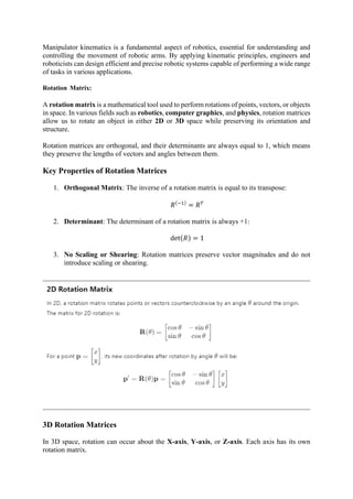
The document offers a comprehensive overview of kinematics in robotics, covering concepts like forward and inverse kinematics, as well as the role of rotation and transformation matrices. It highlights their applications in controlling robotic arms, path planning, and collision detection, emphasizing the importance of mathematically modeling motion. The principles of manipulator kinematics are also detailed, focusing on how joint configurations affect the end effector's movement in 3D space.
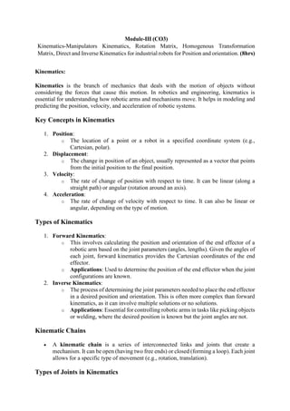
![is represented as (x,y,z,1). A homogeneous transformation matrix combines rotation and
translation like so:
Where:
• R is a 3x3 rotation matrix,
• t is a 3x1 translation vector,
• The last row is [0 0 0 1].
Applications of Rotation Matrices
1. Robotics: Used to control the orientation of robot arms, manipulators, and joints.
2. Computer Graphics: To rotate 3D models, cameras, and objects in virtual
environments.
3. Physics: To describe the rotational motion of rigid bodies.
4. Mechanical Engineering: Analyzing the orientation of components in systems such as
linkages, cranes, and gyroscopic devices.
• Rotation matrices are used to perform rotations in both 2D and 3D space.
• They are orthogonal, meaning their transpose equals their inverse, and their determinant
is always 1.
• In 2D, the rotation matrix is a 2x2 matrix, while in 3D, it can rotate about the X, Y, or
Z axes using specific 3x3 matrices.
• Combined rotations can be represented as the product of multiple rotation matrices.
• Homogeneous coordinates extend rotation matrices to handle both rotation and
translation in 3D space.
Rotation matrices play a crucial role in manipulating objects in a precise, mathematically sound
way in many fields, including robotics, animation, and mechanics.
Homogenous Transformation Matrix:
Homogeneous Transformation Matrix: An Overview
A homogeneous transformation matrix is a mathematical tool used to combine both rotation
and translation in a single matrix. This matrix is widely used in robotics, computer graphics,
and 3D geometry to describe the position and orientation of objects in space.
In 3D space, the transformation of a point or object typically involves:
1. Rotation: Changing the orientation.](https://image.slidesharecdn.com/irnotesmodule-iii-241017071229-aa2a0514/85/B-Tech-5th-Semester-Industrial-Robotics-Notes-Module-III-7-320.jpg)
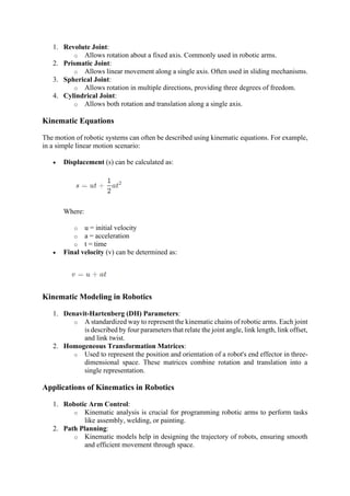
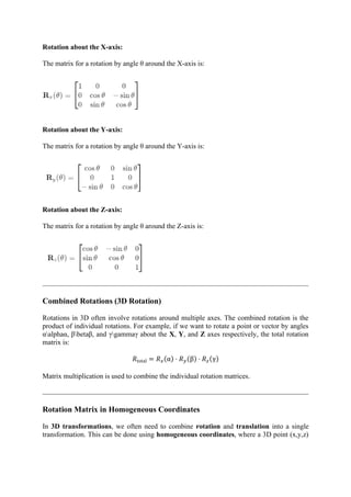
![2. Translation: Changing the position.
The homogeneous transformation matrix allows both operations to be performed
simultaneously. The matrix is 4x4 in size, which enables the inclusion of both rotation and
translation in one operation, and works with homogeneous coordinates, where a 3D point
(x,y,z) is represented as (x,y,z,1).
Structure of a Homogeneous Transformation Matrix
The general form of a 3D homogeneous transformation matrix T is as follows:
𝐓 = [
𝐑 𝐭
0 1
]
Where:
• R is a 3x3 rotation matrix.
• t is a 3x1 translation vector.
• The last row [0 0 0 1] is used to maintain the matrix's homogeneous form.
This matrix operates on a 4x1 vector, where a 3D point is augmented by an additional 1 to
make it a homogeneous coordinate.
Components of the Homogeneous Transformation Matrix
1. Rotation Component (R):
o This is a 3x3 matrix representing the rotation of the object. It defines how an
object or point is rotated around the X, Y, and Z axes.
Example of a rotation matrix:
𝐑𝑧(𝜃) = [
cos𝜃 −sin𝜃 0
sin𝜃 cos𝜃 0
0 0 1
]
2. Translation Component (t):
o This is a 3x1 vector representing the translation (position shift) of the object in
3D space.
𝐭 = [
𝑡𝑥
𝑡𝑦
𝑡𝑧
]
3. Homogeneous Component:
o The last row of the transformation matrix is [0 0 0 1], which allows for both
rotation and translation to be combined into a single transformation.](https://image.slidesharecdn.com/irnotesmodule-iii-241017071229-aa2a0514/85/B-Tech-5th-Semester-Industrial-Robotics-Notes-Module-III-8-320.jpg)
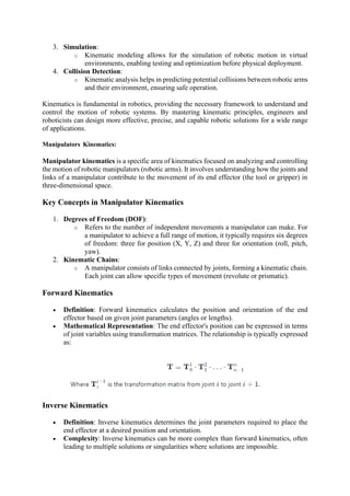
![Homogeneous Transformation Matrix for Rotation and Translation
A homogeneous transformation matrix combines rotation and translation in one operation. If
we have:
• A rotation matrix R (3x3),
• A translation vector 𝐭 = [𝑡𝑥 𝑡𝑦 𝑡𝑧]
𝑇
The resulting homogeneous transformation matrix is:
𝐓 = [
𝑟11 𝑟12 𝑟13 𝑡𝑥
𝑟21 𝑟22 𝑟23 𝑡𝑦
𝑟31 𝑟32 𝑟33 𝑡𝑧
0 0 0 1
]
where 𝑟𝑖𝑗 represents the elements of the rotation matrix 𝐑
Example: Applying a Homogeneous Transformation
Suppose we want to rotate a point around the Z-axis by an angle θ and then translate it by
(tx,ty,tz).
1. Rotation around the Z-axis is represented by the matrix:
𝐑𝑧(𝜃) = [
cos𝜃 −sin𝜃 0
sin𝜃 cos𝜃 0
0 0 1
]
2. Translation is given by:
𝐭 = [
𝑡𝑥
𝑡𝑦
𝑡𝑧
]
3. Homogeneous Transformation Matrix T:
𝐓 = [
cos𝜃 −sin𝜃 0 𝑡𝑥
sin𝜃 cos𝜃 0 𝑡𝑦
0 0 1 𝑡𝑧
0 0 0 1
]
If you have a point 𝐩 = [
𝑥
𝑦
𝑧
1
], then the transformed point p′ is:
𝐩′ = 𝐓 · 𝐩
Applications of the Homogeneous Transformation Matrix](https://image.slidesharecdn.com/irnotesmodule-iii-241017071229-aa2a0514/85/B-Tech-5th-Semester-Industrial-Robotics-Notes-Module-III-9-320.jpg)
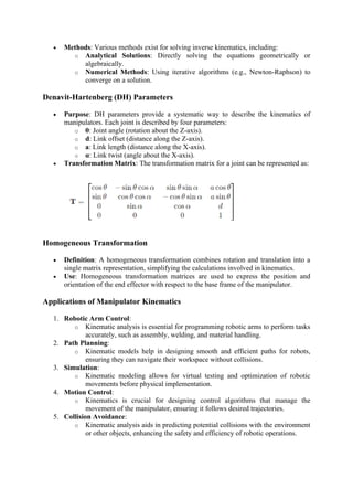
![1. Robotics: It is used to describe the position and orientation of robot arms
(manipulators) in space. For example, in the Denavit-Hartenberg (D-H) Convention,
homogeneous transformation matrices are used to compute forward and inverse
kinematics.
2. Computer Graphics: Homogeneous matrices allow objects to be transformed, rotated,
and moved in 3D environments. Cameras and models are manipulated using these
matrices.
3. Kinematics and Dynamics: In mechanical engineering and physics, these matrices
describe the motion and orientation of rigid bodies.
Summary
• The homogeneous transformation matrix combines rotation and translation in 3D
space into a single 4x4 matrix.
• The matrix consists of a 3x3 rotation matrix and a 3x1 translation vector, with a
homogeneous component to handle both operations in one matrix multiplication.
• These matrices are essential in robotics, computer graphics, and 3D geometry for
transforming points, vectors, and objects in space.
This matrix allows for powerful and efficient calculations for manipulating objects in a wide
variety of fields.
Direct and Inverse Kinematics for industrial robots for Position and orientation:
Direct Kinematics (Forward Kinematics): 𝐓 = 𝐓0
1
· 𝐓1
2
· 𝐓2
3
⋯ 𝐓𝑛−1
𝑛
𝐩 = [
𝑥
𝑦
𝑧
] = [
𝑡𝑥
𝑡𝑦
𝑡𝑧
] = 𝐓3×1
Inverse Kinematics: 𝐓 = [
𝑅 𝑡
0 1
] 𝐪 = 𝑓−1(𝐓)
Direct and Inverse Kinematics for Industrial Robots
In industrial robotics, kinematics is the study of motion without considering the forces that
cause it. Kinematics focuses on the relationships between the position, orientation, velocity,
and acceleration of robot arms or manipulators.
There are two primary types of kinematics: Direct Kinematics (Forward Kinematics) and
Inverse Kinematics.
1. Direct Kinematics (Forward Kinematics)
Direct Kinematics refers to the process of determining the position and orientation of the end
effector (the tool or device at the end of the robotic arm) based on given joint parameters
(angles, distances, etc.).
Mathematical Representation:](https://image.slidesharecdn.com/irnotesmodule-iii-241017071229-aa2a0514/85/B-Tech-5th-Semester-Industrial-Robotics-Notes-Module-III-10-320.jpg)
![For a robotic manipulator with nnn joints, the position of the end effector p can be calculated
using the joint variables q (which can be angles for revolute joints or distances for prismatic
joints) and a series of transformation matrices.
The overall transformation from the base frame to the end effector frame can be represented
as:
𝐓 = 𝐓0
1
· 𝐓1
2
· 𝐓2
3
⋯ 𝐓𝑛−1
𝑛
Where:
• Tij is the transformation matrix from frame i to frame j.
• T is the overall transformation matrix.
The position and orientation of the end effector can be extracted from the transformation matrix
T:
𝐩 = [
𝑥
𝑦
𝑧
] = [
𝑡𝑥
𝑡𝑦
𝑡𝑧
] = 𝐓3×1
Where 𝑡𝑥, 𝑡𝑦, 𝑡𝑧 are the translation components of the transformation matrix.
2. Inverse Kinematics
Inverse Kinematics is the process of calculating the joint parameters needed to place the end
effector in a desired position and orientation. This is often more complex than direct kinematics
due to the multiple configurations (or solutions) that can achieve the same end effector pose.
Mathematical Representation:
To find the joint parameters q given the desired position p and orientation, we can use the
transformation matrix T:
𝐓 = [
𝐑 𝐭
0 1
]
Where:
• R is the rotation matrix describing the orientation.
• t is the translation vector.
To solve for joint parameters, we need to establish the relationship between T and the joint
variables q:
𝐪 = 𝑓−1(𝐓)](https://image.slidesharecdn.com/irnotesmodule-iii-241017071229-aa2a0514/85/B-Tech-5th-Semester-Industrial-Robotics-Notes-Module-III-11-320.jpg)