🤖 What Is Robot Kinematics and Dynamics?
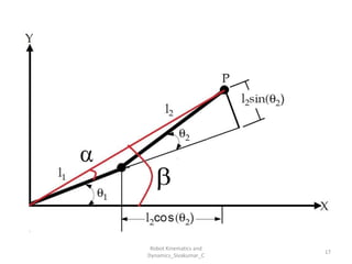
Robot Kinematics
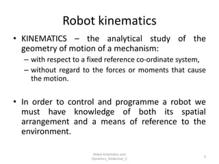
- Focuses on the geometry of motion without considering forces.
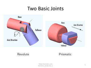
- Describes how joints and links move relative to each other.
- Includes:
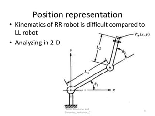
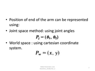
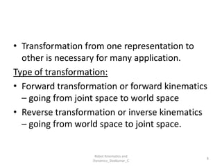
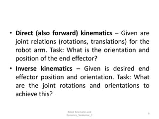
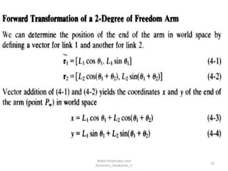
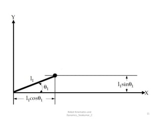
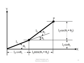
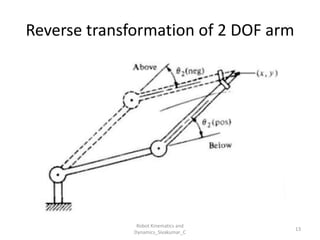
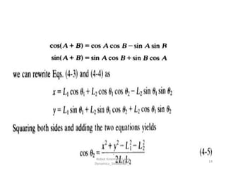
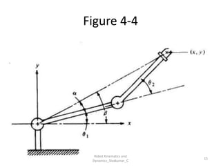
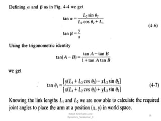
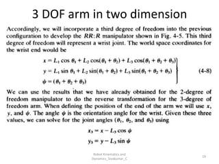
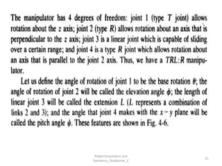
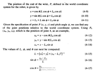
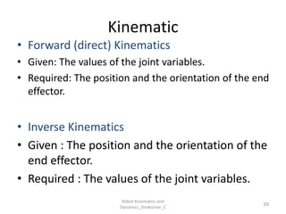
- Forward kinematics: Given joint parameters → find end-effector position.
- Inverse kinematics: Given end-effector position → find joint parameters.
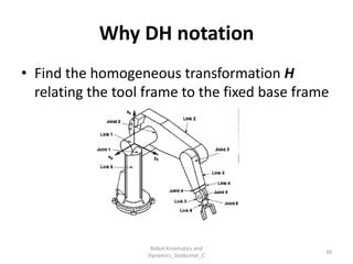
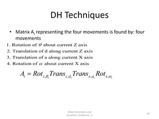
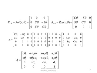
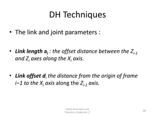
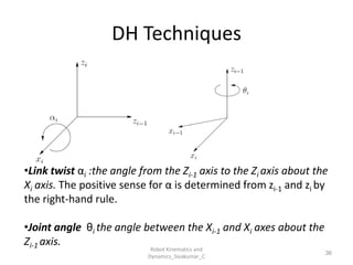
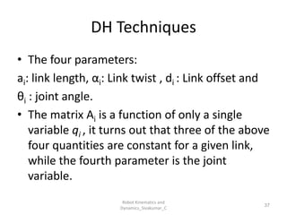
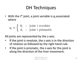
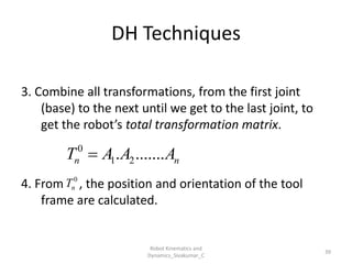
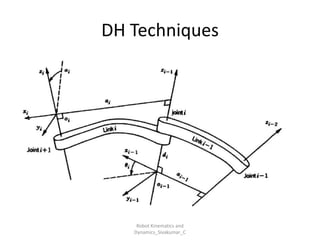
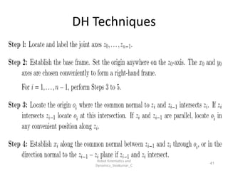
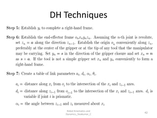
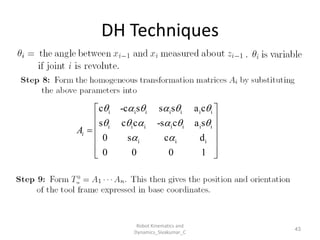
- Uses tools like Denavit-Hartenberg (D-H) parameters, transformation matrices, and coordinate frames.
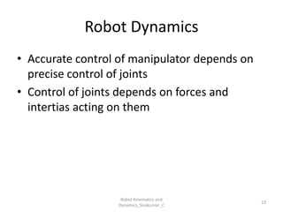
Robot Dynamics
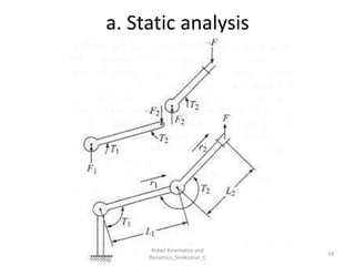
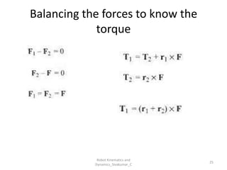
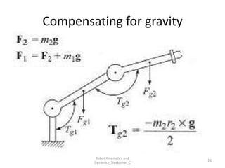
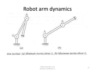
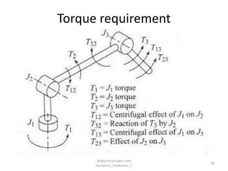
- Studies the forces and torques that cause motion.
- Involves:
- Newton-Euler and Lagrangian formulations.
- Modeling inertia, friction, and external forces.
- Calculating joint torques for control and simulation.
---
🛠️ Mechanical Engineering Relevance
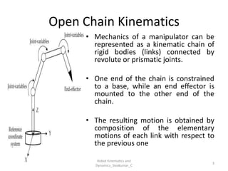
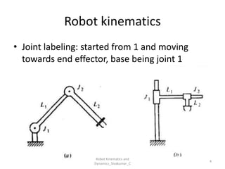
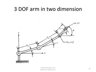
- Robots are modeled as kinematic chains of rigid bodies (links) connected by joints.
- Mechanical engineers use these principles to:
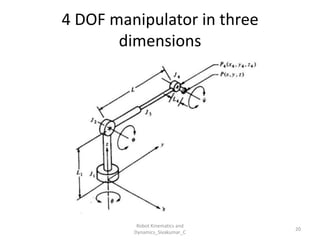
- Design manipulators and mobile robots.
- Simulate motion and control systems.
- Analyze torque requirements and stability
You can explore this detailed PDF on Robot Kinematics and Dynamics from BSA Crescent Institute. It includes examples of RR and LL robots, D-H modeling, and joint control strategies.