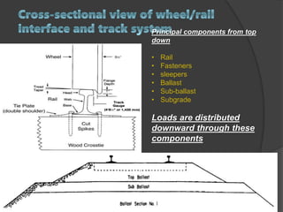
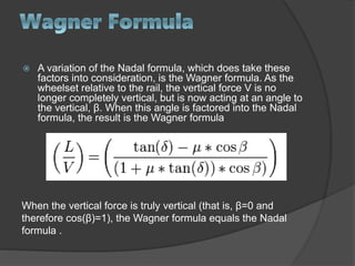
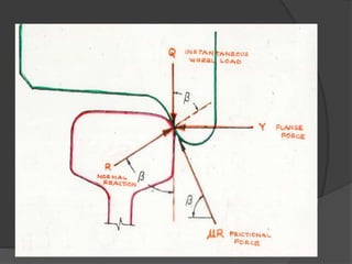
 The axle load of a wheeled Rail is the
total weight felt by the railway for all
wheels connected to a given axle.
 Viewed another way, it is the fraction of
total Train weight resting on a given
axle.
 Axle load is an important design
consideration in the engineering of
railways and roadways, as both are
designed to tolerate a maximum weight-
per-axle (axle load); exceeding the
maximum rated axle load will cause
damage to the roadway or rail tracks.
The vehicle axle load is usually measured for the
Static condition, but in the design of railway track the actual
stresses in the various components of the track structure and in
the rolling stock must be determined from the dynamic vertical
condition and lateral forces imposed by the design Train moving
at speed.
The dynamic wheel loads cause increases in the rail stress values
above those of the static condition due to the following factors:
1. lateral bending of the rail .
2. eccentric vertical loading .
3. transfer of the wheel loads due to the rolling action of
the train .
4. vertical impact of wheel on rail due to speed .
 The maximum axle load is related to the
strength of the track .
 strength of the track is determined by :
1. Weight of Rails .
2. density of sleepers .
3. track stability .
4. amount of ballast .
5. strength of bridges .
 Loads are transferred
from the Wagon body into
truck and track structure
via the:
 – center-bowl (1)
 – bolster (1)
 – spring-groups (2)
 – side frames (2)
 – bearing adaptors (4)
 – bearings (4)
 – axle journals (4)
 – wheels (4)
 – rails (2)
 – sleepers (many)
 – ballast
Principal components from top
down
• Rail
• Fasteners
• sleepers
• Ballast
• Sub-ballast
• Subgrade
Loads are distributed
downward through these
components
 Rail is the single most valuable asset
owned by the railroad industry.
 It is probably the most critical element
of track system.
 Provides smooth, low-friction, running
surface, Wide, flat base distributes load
across several crossties and allows
fasteners and other stabilizing
components to be attached
Combined with fasteners and ties,
provides a stable track gauge .
 The sleepers supports the rail and distributes
the load over a larger section of the sleepers
surface.
 Fasteners hold the track in gauge and do not
provide much vertical restraint.
 Along with fasteners, sleepers provide
gauge restraint and further distribute the
load into the ballast.
Ballast and sub-ballast are the final stages in load distribution
In addition to distributing vertical loads, ballast has a critical role
maintaining longitudinal and lateral stability of track.
Flange on the inside is
stable, rather then
unstable, when there is
a lateral force such as
in curves.
 As a load is applied, it
results in both
downward and upward
forces on the rail and
consequently the track
structure.
 This “pumping” action
as wheels pass over it
tends to loosen, wear
and damage track
components
lateral force :
the force of the wheel flange pushing
out on the rail.
vertical force :
the wheel load of the equipment
bearing down on the rail
 In order for a wheel's
flange to climb up the
gage face of a rail and
over the rail head to the
outside of the track, the
wheel lateral and vertical
forces must be such that
the vertical force that
acts to keep the wheel
on the rail is overcome
by the lateral force and
the friction forces that
exist between the
wheel's flange and the
gage face of the rail.
 L/V quantifies the ratio between the force of the
wheel flange pushing out on the rail (lateral
force) and the wheel load of the equipment
bearing down on the rail (vertical force). The
single wheel L/V ratio can be used to predict the
risk of a wheel climbing the gauge face of the rail
or lifting off the rail. Similarly, the combined
forces for the wheels on one truck side exerting
high lateral forces onto the same rail can cause
rail-head deflection, reverse-rail cant, or lateral-
rail displacement, resulting in gauge spread or
rollover.
 AAR guidelines indicate that truck side L/V
values should not exceed 0.6
 The Nadal formula, also called Nadal's
formula, is an equation in railway design
that relates the downward force exerted by
a train’s wheels upon the rail, with the
lateral force of the wheel's flange against
the face of the rail. This relationship is
significant in railway design, as a wheel-
climb derailment may occur if the lateral
and vertical forces are not properly
considered
L and V : refer to the lateral and vertical forces acting upon the rail and wheel
δ : is the angle made when the wheel flange is in contact with the rail face
μ : is the coefficient of friction between the wheel and the rail .
 Typically, the axel load for a railway
vehicle should be such that the lateral
forces of the wheel against the rail
should not exceed 50% of the vertical
down-force of the vehicle on the
rail. Put another way, there should be
twice as much downward force
holding the wheel to the rail, as there is
lateral force which will tend to cause the
wheel to climb in turns .
 This ratio is accomplished by matching
the wheel-axle assembly of railroad
car (wheelset) with the appropriate rail
profile to achieve the L/V ratio desired.
 If the L/V ratio gets too high, the wheel
flange will be pressing against the rail
face, and during a turn this will cause
the wheel to climb the face of the rail,
potentially derailing the railcar .
 The Nadal formula assumes the wheel
remains perpendicular to the rail—it
does not take into account hunting
oscillation of the wheel-axle assembly
of rail car (wheelset), or the movement
of the wheel flange contact point against
the rail.
 A variation of the Nadal formula, which does take these
factors into consideration, is the Wagner formula. As the
wheelset relative to the rail, the vertical force V is no
longer completely vertical, but is now acting at an angle to
the vertical, β. When this angle is factored into the Nadal
formula, the result is the Wagner formula
When the vertical force is truly vertical (that is, β=0 and
therefore cos(β)=1), the Wagner formula equals the Nadal
formula .
Axle load for Rail way - linkedin

Axle load for Rail way - linkedin

  • 2.
     The axleload of a wheeled Rail is the total weight felt by the railway for all wheels connected to a given axle.  Viewed another way, it is the fraction of total Train weight resting on a given axle.
  • 3.
     Axle loadis an important design consideration in the engineering of railways and roadways, as both are designed to tolerate a maximum weight- per-axle (axle load); exceeding the maximum rated axle load will cause damage to the roadway or rail tracks.
  • 4.
    The vehicle axleload is usually measured for the Static condition, but in the design of railway track the actual stresses in the various components of the track structure and in the rolling stock must be determined from the dynamic vertical condition and lateral forces imposed by the design Train moving at speed. The dynamic wheel loads cause increases in the rail stress values above those of the static condition due to the following factors: 1. lateral bending of the rail . 2. eccentric vertical loading . 3. transfer of the wheel loads due to the rolling action of the train . 4. vertical impact of wheel on rail due to speed .
  • 5.
     The maximumaxle load is related to the strength of the track .  strength of the track is determined by : 1. Weight of Rails . 2. density of sleepers . 3. track stability . 4. amount of ballast . 5. strength of bridges .
  • 6.
     Loads aretransferred from the Wagon body into truck and track structure via the:  – center-bowl (1)  – bolster (1)  – spring-groups (2)  – side frames (2)  – bearing adaptors (4)  – bearings (4)  – axle journals (4)  – wheels (4)  – rails (2)  – sleepers (many)  – ballast
  • 7.
    Principal components fromtop down • Rail • Fasteners • sleepers • Ballast • Sub-ballast • Subgrade Loads are distributed downward through these components
  • 8.
     Rail isthe single most valuable asset owned by the railroad industry.  It is probably the most critical element of track system.  Provides smooth, low-friction, running surface, Wide, flat base distributes load across several crossties and allows fasteners and other stabilizing components to be attached Combined with fasteners and ties, provides a stable track gauge .
  • 9.
     The sleeperssupports the rail and distributes the load over a larger section of the sleepers surface.  Fasteners hold the track in gauge and do not provide much vertical restraint.
  • 10.
     Along withfasteners, sleepers provide gauge restraint and further distribute the load into the ballast.
  • 11.
    Ballast and sub-ballastare the final stages in load distribution In addition to distributing vertical loads, ballast has a critical role maintaining longitudinal and lateral stability of track.
  • 12.
    Flange on theinside is stable, rather then unstable, when there is a lateral force such as in curves.
  • 13.
     As aload is applied, it results in both downward and upward forces on the rail and consequently the track structure.  This “pumping” action as wheels pass over it tends to loosen, wear and damage track components
  • 16.
    lateral force : theforce of the wheel flange pushing out on the rail. vertical force : the wheel load of the equipment bearing down on the rail
  • 17.
     In orderfor a wheel's flange to climb up the gage face of a rail and over the rail head to the outside of the track, the wheel lateral and vertical forces must be such that the vertical force that acts to keep the wheel on the rail is overcome by the lateral force and the friction forces that exist between the wheel's flange and the gage face of the rail.
  • 18.
     L/V quantifiesthe ratio between the force of the wheel flange pushing out on the rail (lateral force) and the wheel load of the equipment bearing down on the rail (vertical force). The single wheel L/V ratio can be used to predict the risk of a wheel climbing the gauge face of the rail or lifting off the rail. Similarly, the combined forces for the wheels on one truck side exerting high lateral forces onto the same rail can cause rail-head deflection, reverse-rail cant, or lateral- rail displacement, resulting in gauge spread or rollover.  AAR guidelines indicate that truck side L/V values should not exceed 0.6
  • 19.
     The Nadalformula, also called Nadal's formula, is an equation in railway design that relates the downward force exerted by a train’s wheels upon the rail, with the lateral force of the wheel's flange against the face of the rail. This relationship is significant in railway design, as a wheel- climb derailment may occur if the lateral and vertical forces are not properly considered
  • 20.
    L and V: refer to the lateral and vertical forces acting upon the rail and wheel δ : is the angle made when the wheel flange is in contact with the rail face μ : is the coefficient of friction between the wheel and the rail .
  • 21.
     Typically, theaxel load for a railway vehicle should be such that the lateral forces of the wheel against the rail should not exceed 50% of the vertical down-force of the vehicle on the rail. Put another way, there should be twice as much downward force holding the wheel to the rail, as there is lateral force which will tend to cause the wheel to climb in turns .
  • 22.
     This ratiois accomplished by matching the wheel-axle assembly of railroad car (wheelset) with the appropriate rail profile to achieve the L/V ratio desired.  If the L/V ratio gets too high, the wheel flange will be pressing against the rail face, and during a turn this will cause the wheel to climb the face of the rail, potentially derailing the railcar .
  • 23.
     The Nadalformula assumes the wheel remains perpendicular to the rail—it does not take into account hunting oscillation of the wheel-axle assembly of rail car (wheelset), or the movement of the wheel flange contact point against the rail.
  • 25.
     A variationof the Nadal formula, which does take these factors into consideration, is the Wagner formula. As the wheelset relative to the rail, the vertical force V is no longer completely vertical, but is now acting at an angle to the vertical, β. When this angle is factored into the Nadal formula, the result is the Wagner formula When the vertical force is truly vertical (that is, β=0 and therefore cos(β)=1), the Wagner formula equals the Nadal formula .