Downloaded 200 times
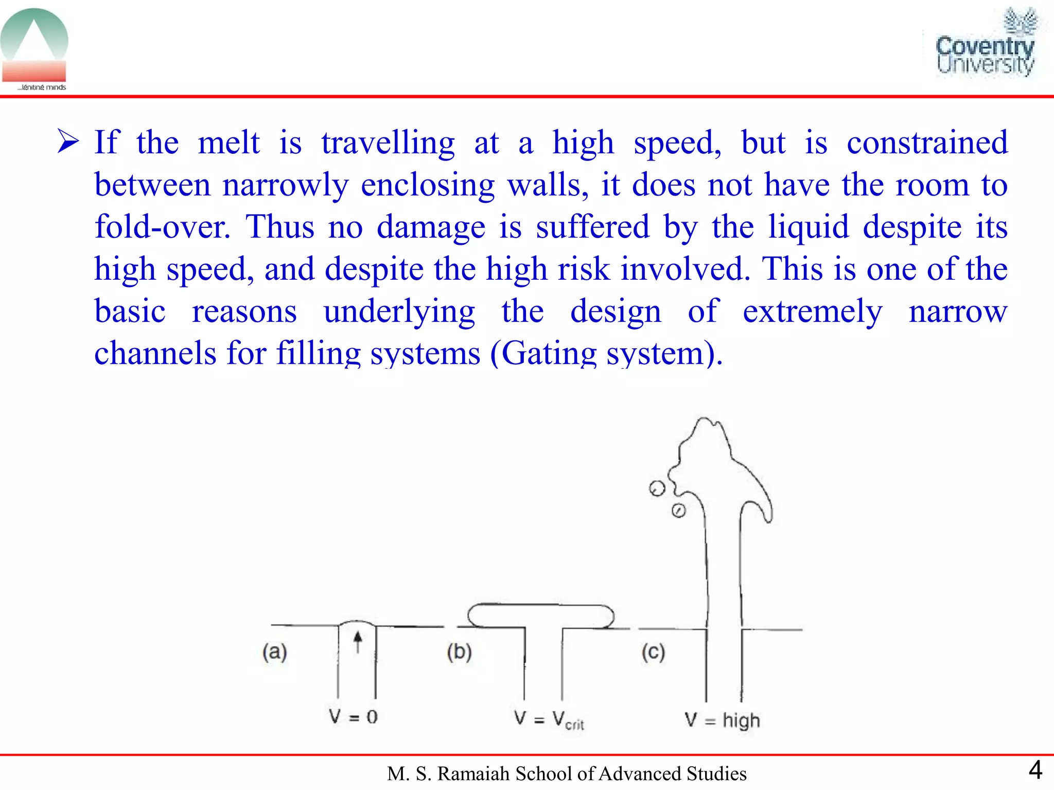
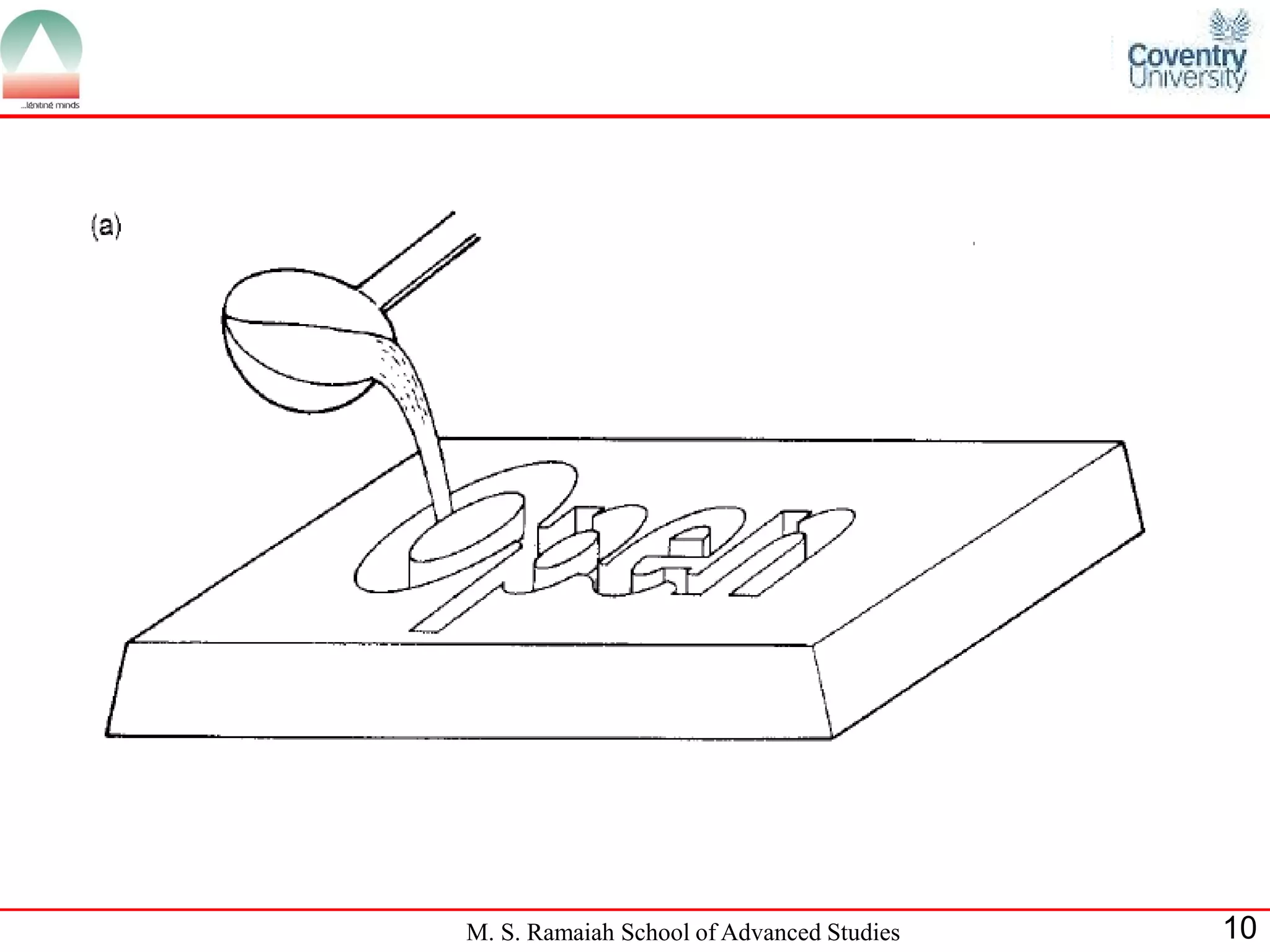
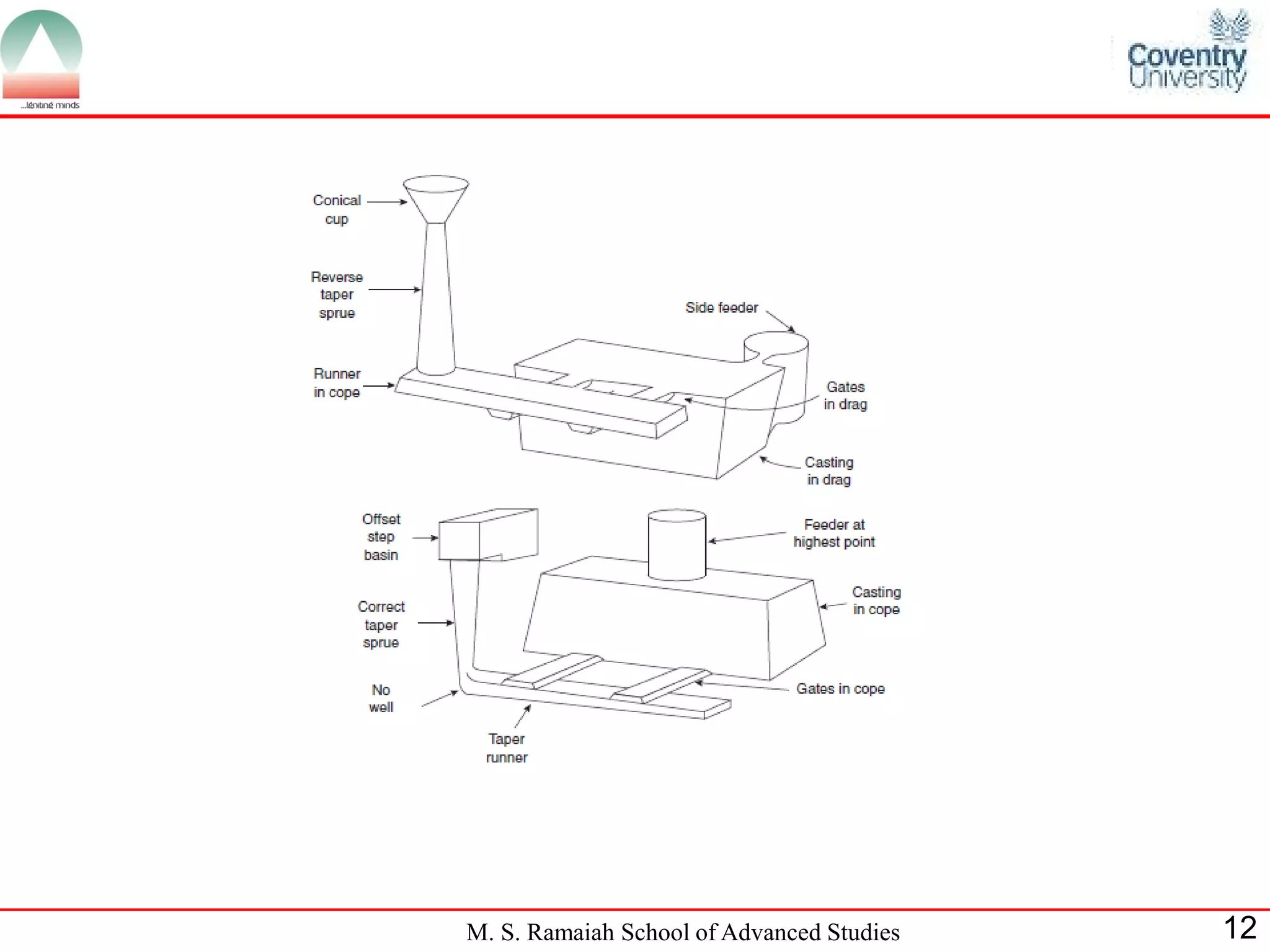
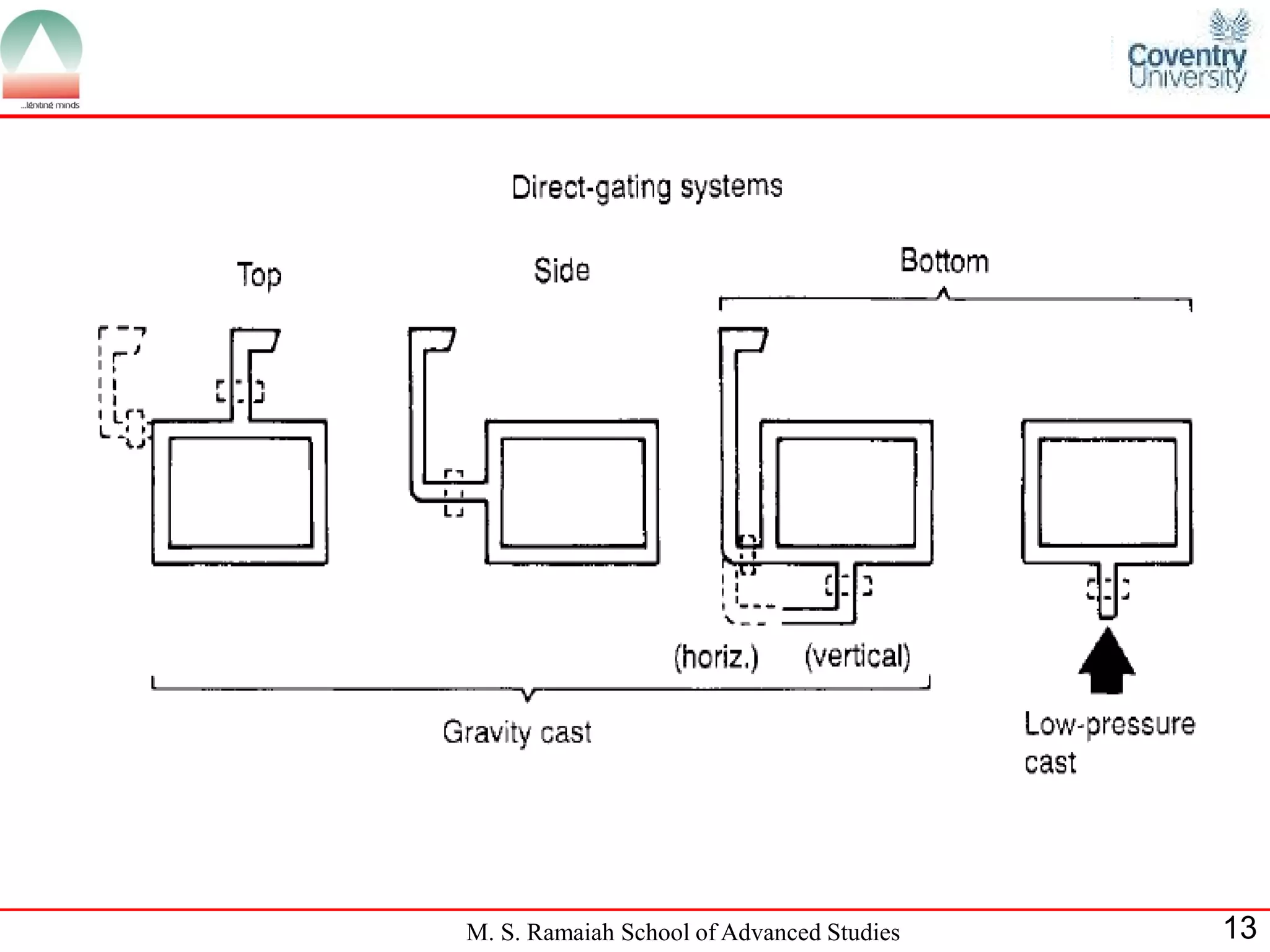
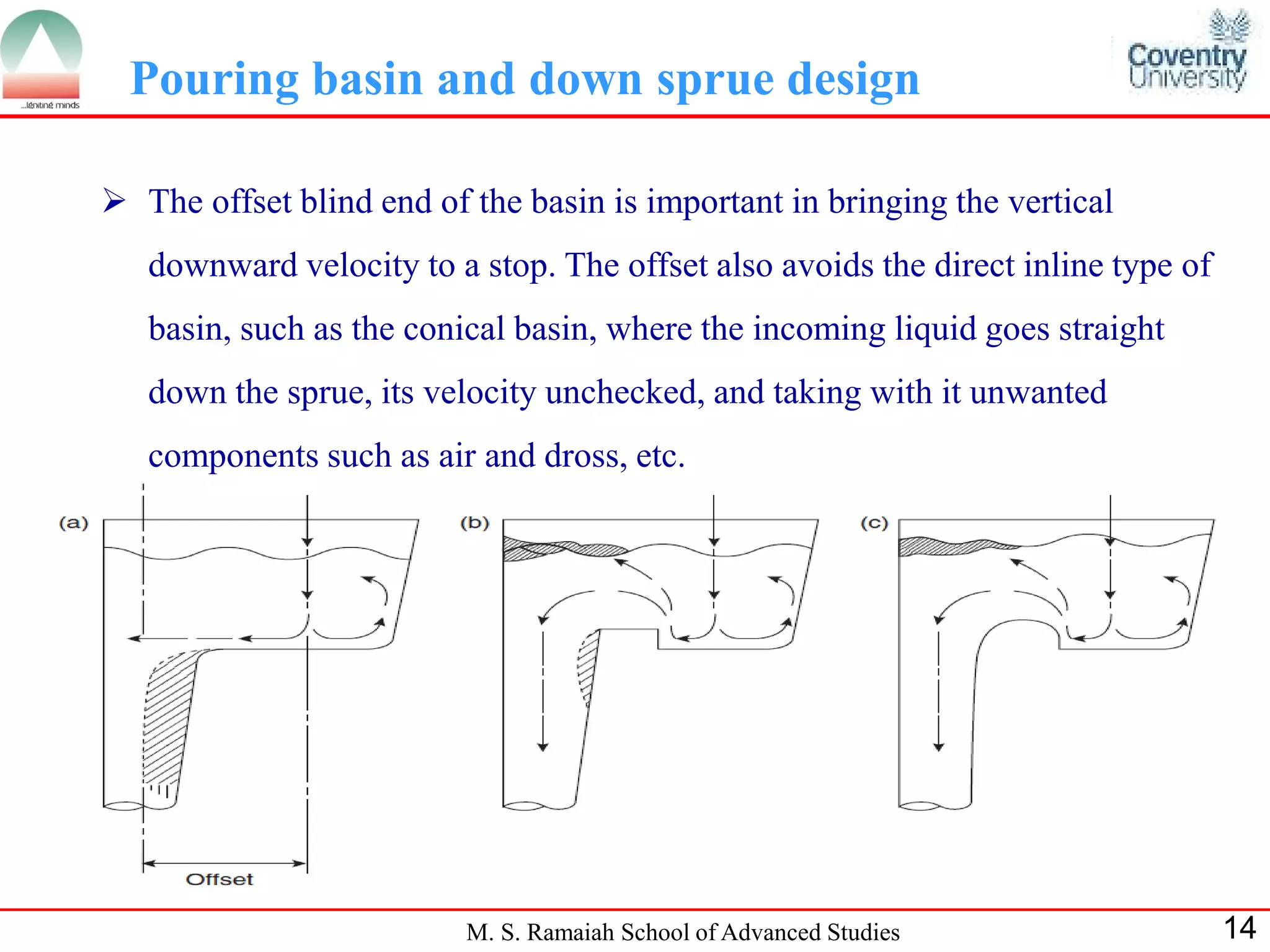
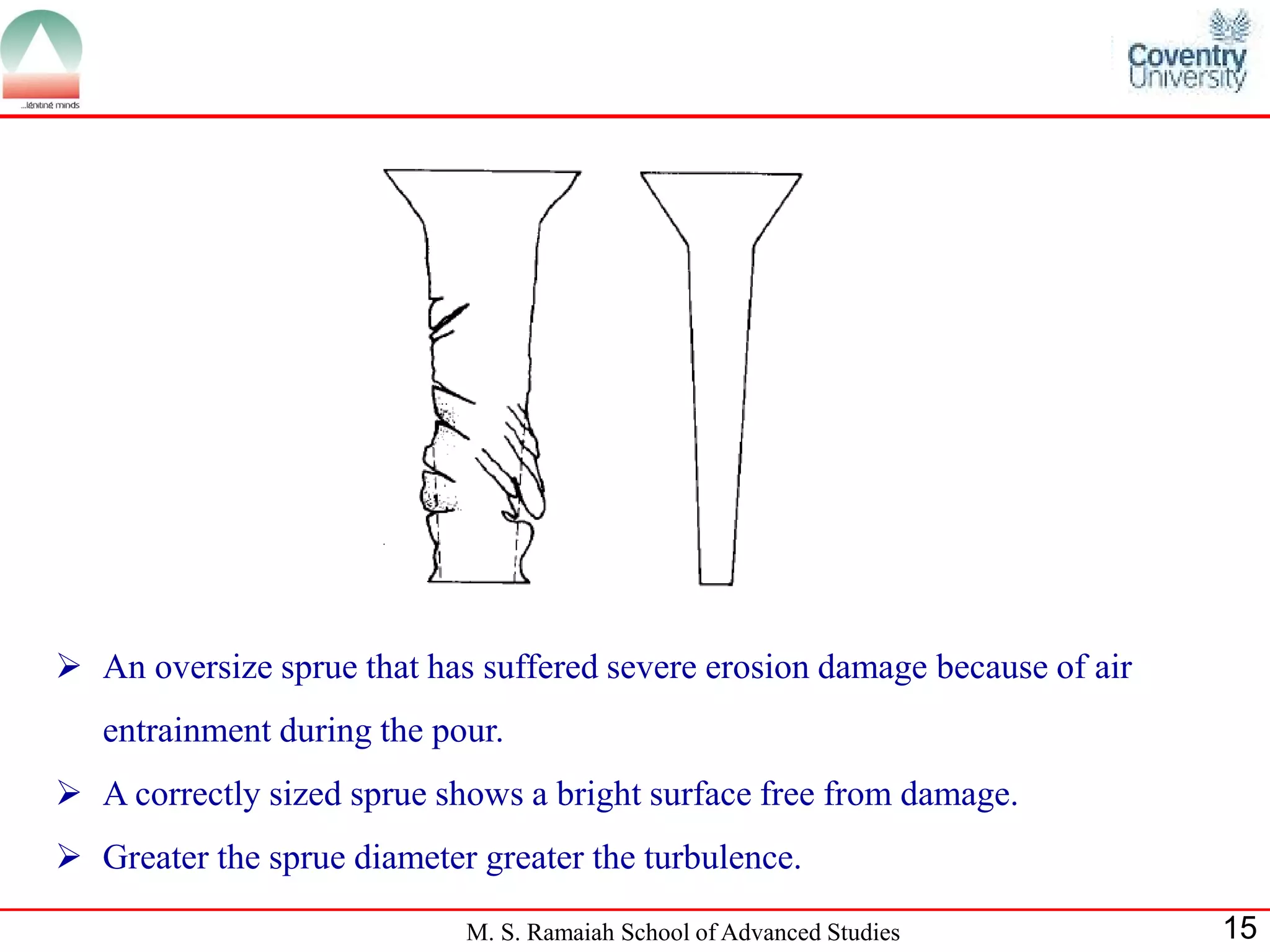
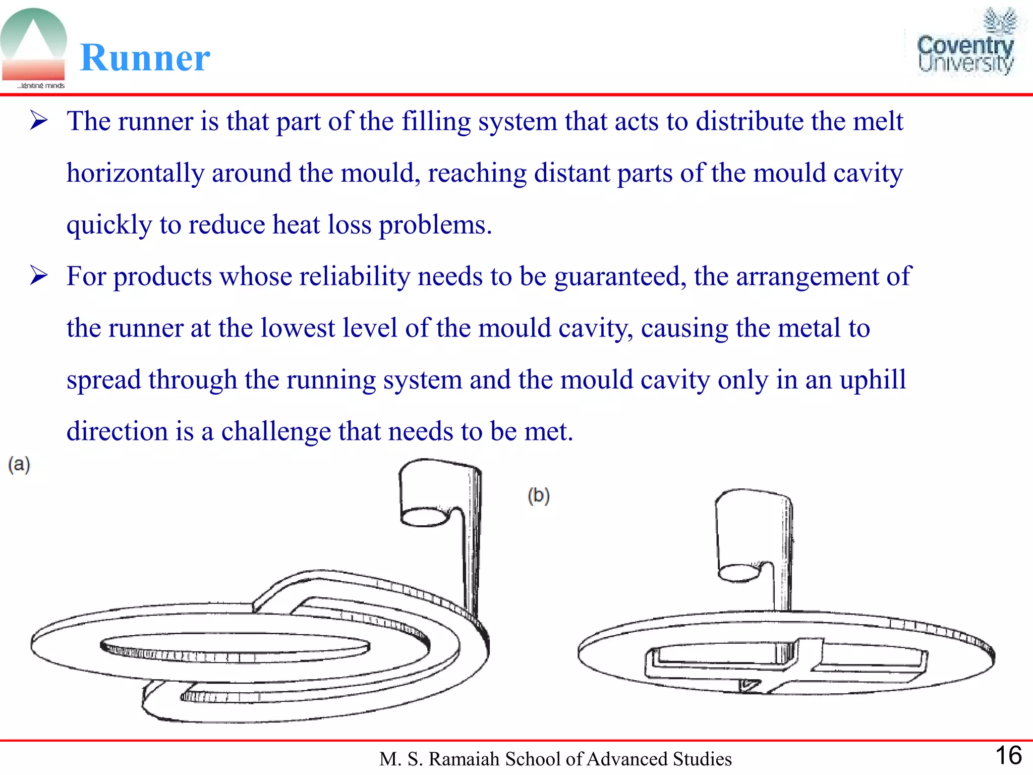
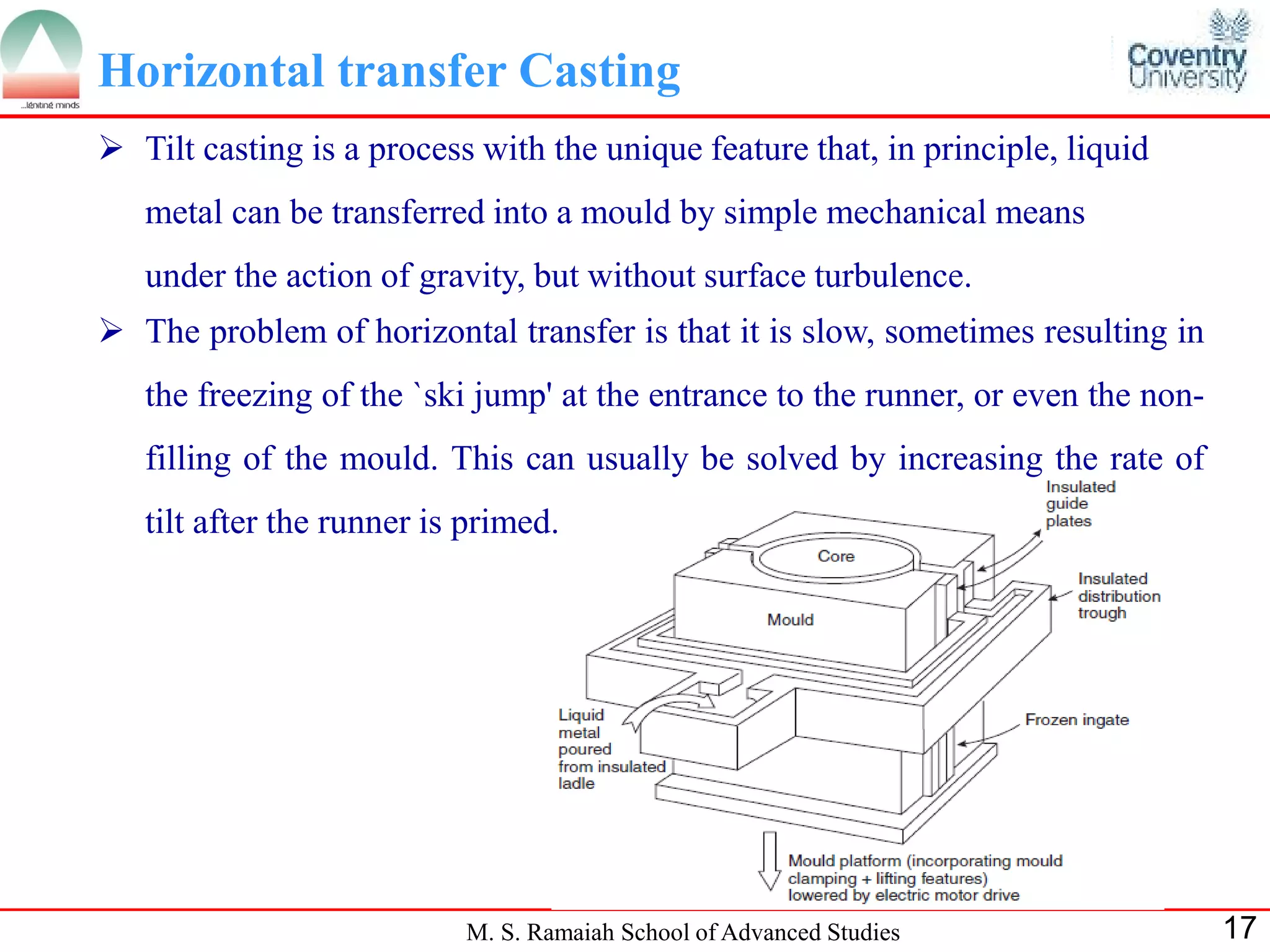

This document discusses metal casting and joining processes. It addresses several key requirements for avoiding defects when pouring molten metal into molds, including avoiding velocities above the critical velocity to prevent entrainment, designing narrow channels to constrain the flow, and ensuring the metal does not fall more than 15mm to limit turbulence. It also describes considerations for different filling system designs like gravity pouring into open or closed molds, and techniques like using offset pouring basins and designing sprues and runners to efficiently distribute the flow. Horizontal transfer casting is also discussed as a way to move liquid metal without surface turbulence.


![SY Lectures Gating designe, Raisers Problems[1].pdf](https://cdn.slidesharecdn.com/ss_thumbnails/sylecturesgatingdesigneraisersproblems1-240402183803-58d6d3a8-thumbnail.jpg?width=640&height=640&fit=bounds)


![Coded Agents – with UiPath SDK + LangGraph [Virtual Hands-on Workshop]](https://cdn.slidesharecdn.com/ss_thumbnails/codedagentsdeck-251215155422-5497c599-thumbnail.jpg?width=640&height=640&fit=bounds)


