The document provides an overview of computer-aided design (CAD) software and the AutoCAD interface. It discusses the history and benefits of CAD, the differences between manual and CAD drafting, and explores the various components of the AutoCAD interface such as the ribbon, workspace, drawing area, command window, and object snaps. It also describes common commands for zooming, panning, selecting objects, and setting display options in AutoCAD.


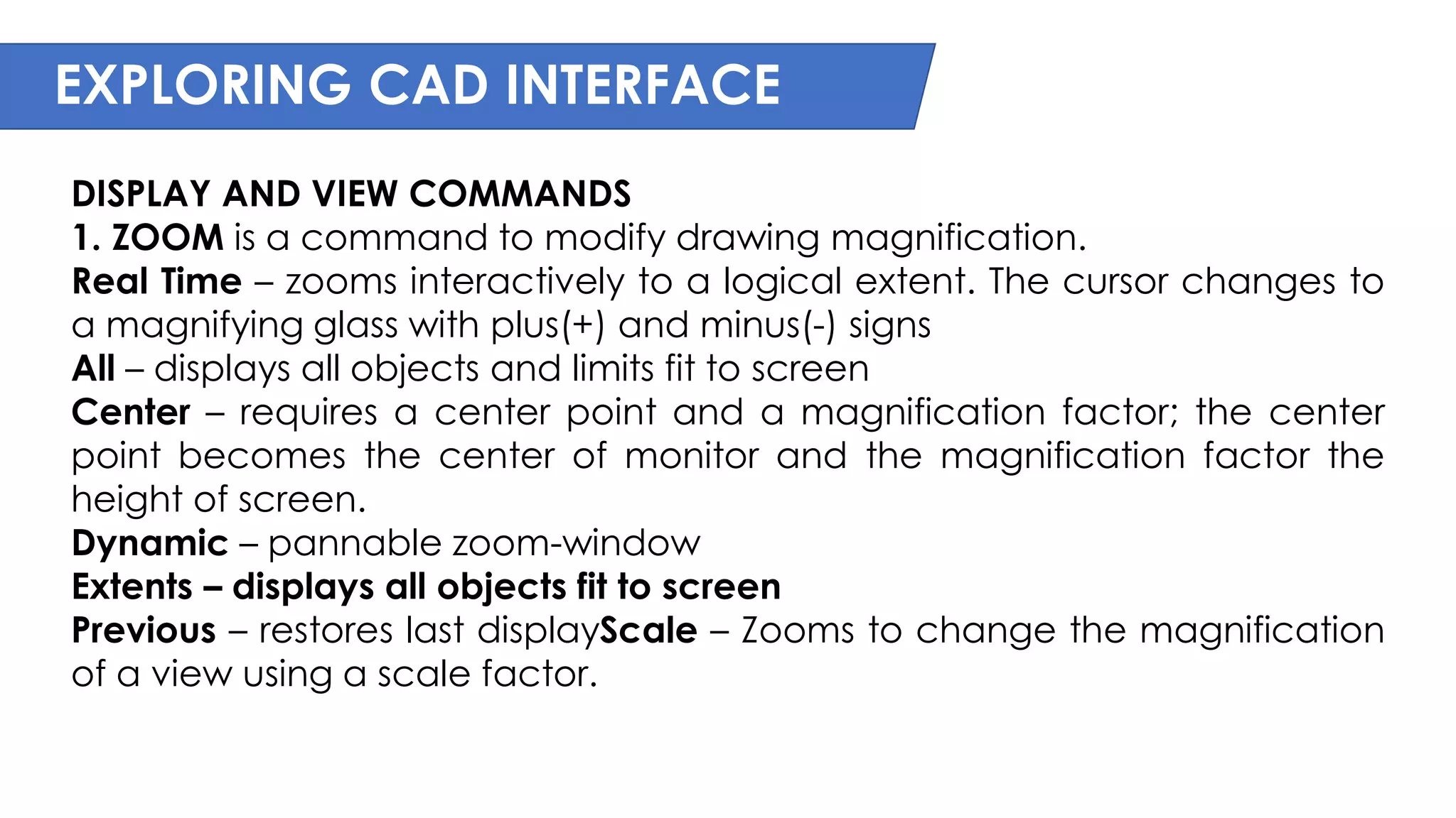
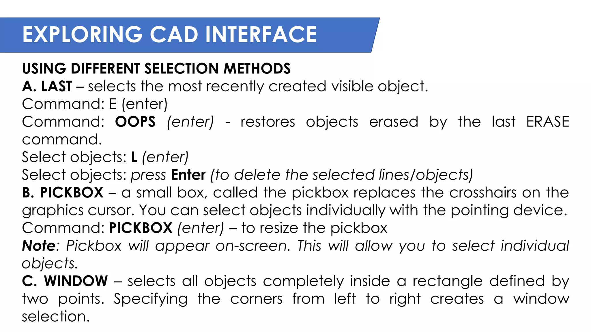
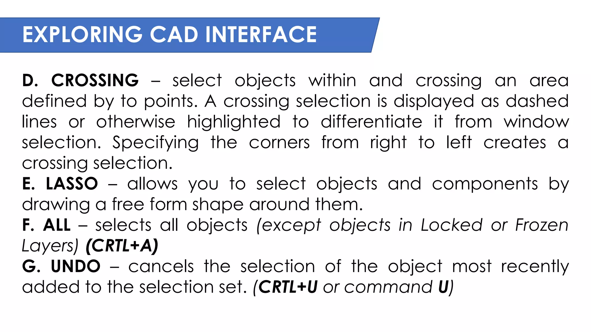
![EXPLORING CAD INTERFACE
MODEL SPACE VIEWPORT CONTROLS - are displayed at the top-
left corner of each viewport, and provide a convenient way of
changing views, visual styles, and other settings. (See figure 2)
You can click within each of the three bracketed areas to
change the settings.
[+] [Top] [2D Wireframe]
• Click + to display options for maximizing the viewport,
changing the viewport configuration, or controlling the display
of navigation tools.
• Click Top to choose between several standard and custom
views.
• Click 2D Wireframe to choose one of several visual styles. Most
of the other visual styles are used for 3D visualization](https://image.slidesharecdn.com/autocad-review-2-230915015703-d6e3a913/75/AUTOCAD-REVIEW-2-pdf-24-2048.jpg)