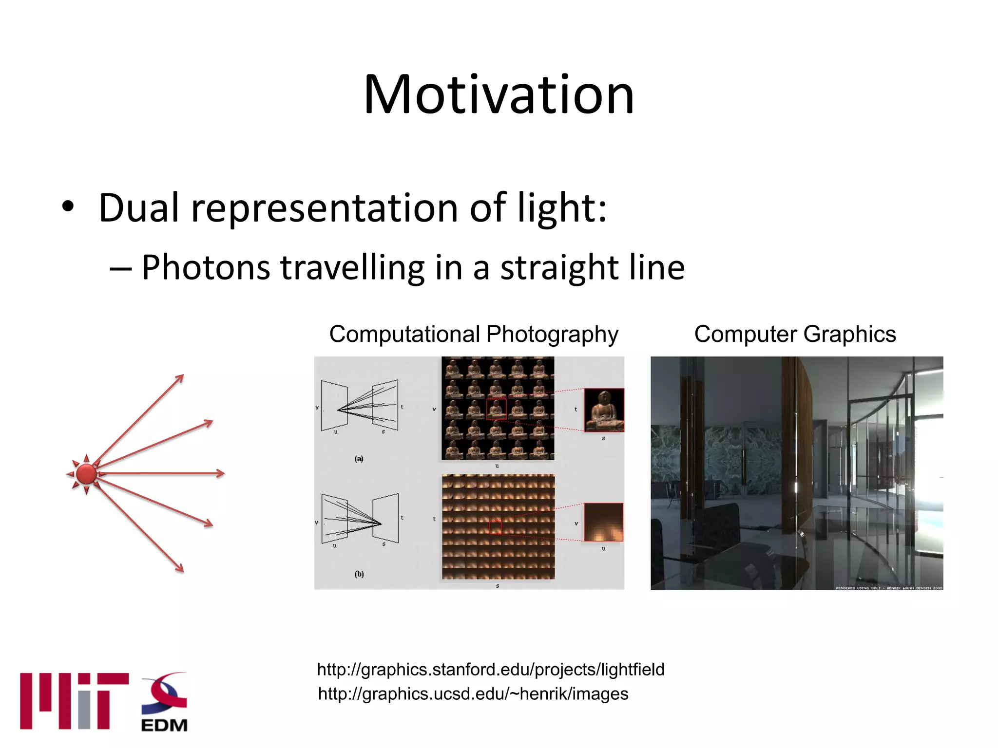
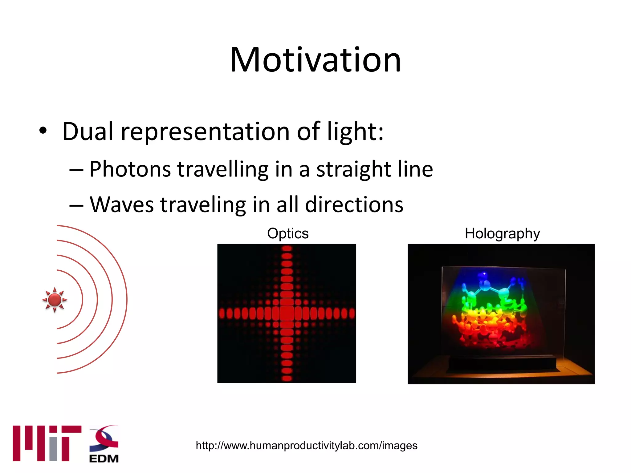
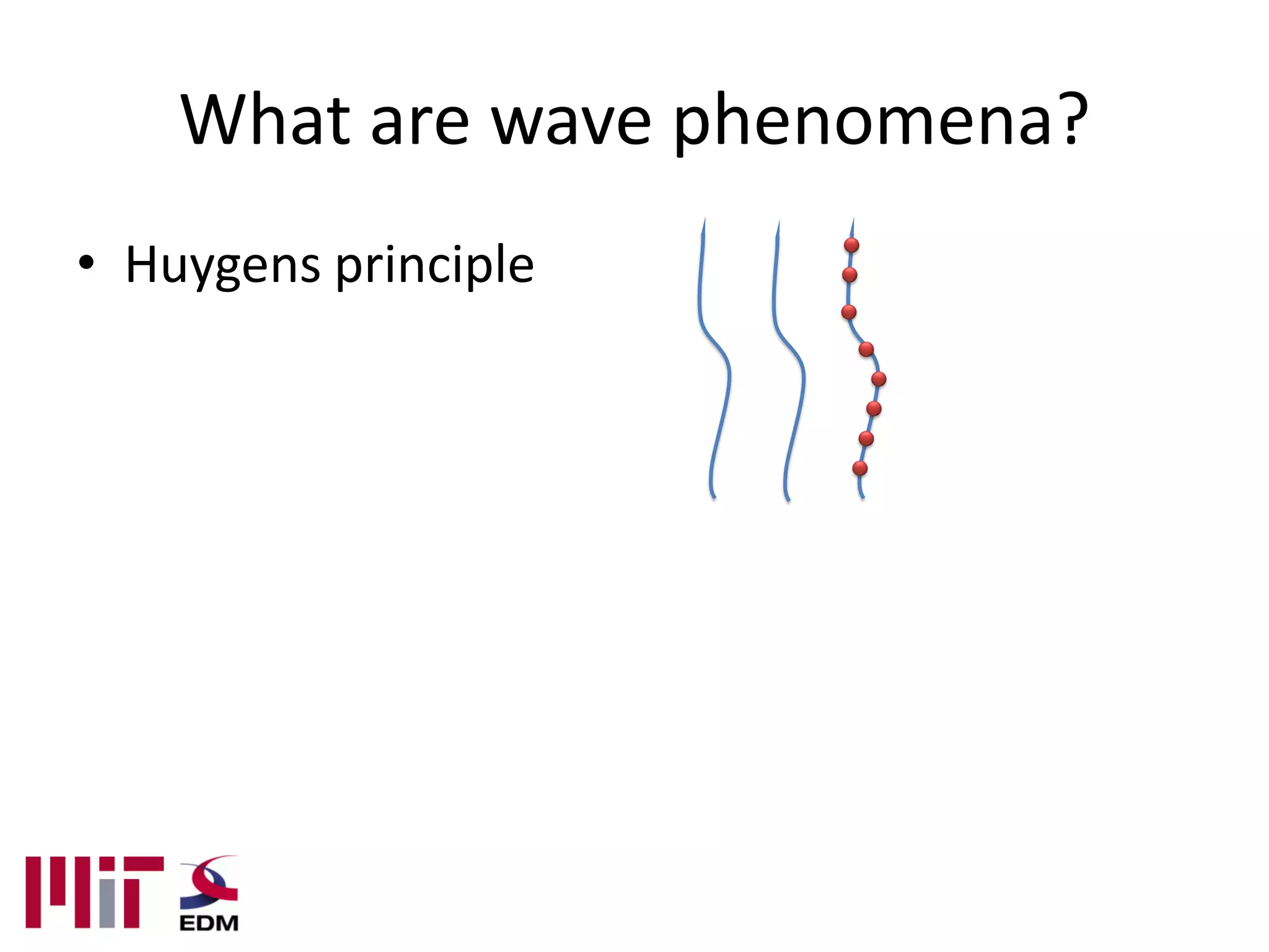
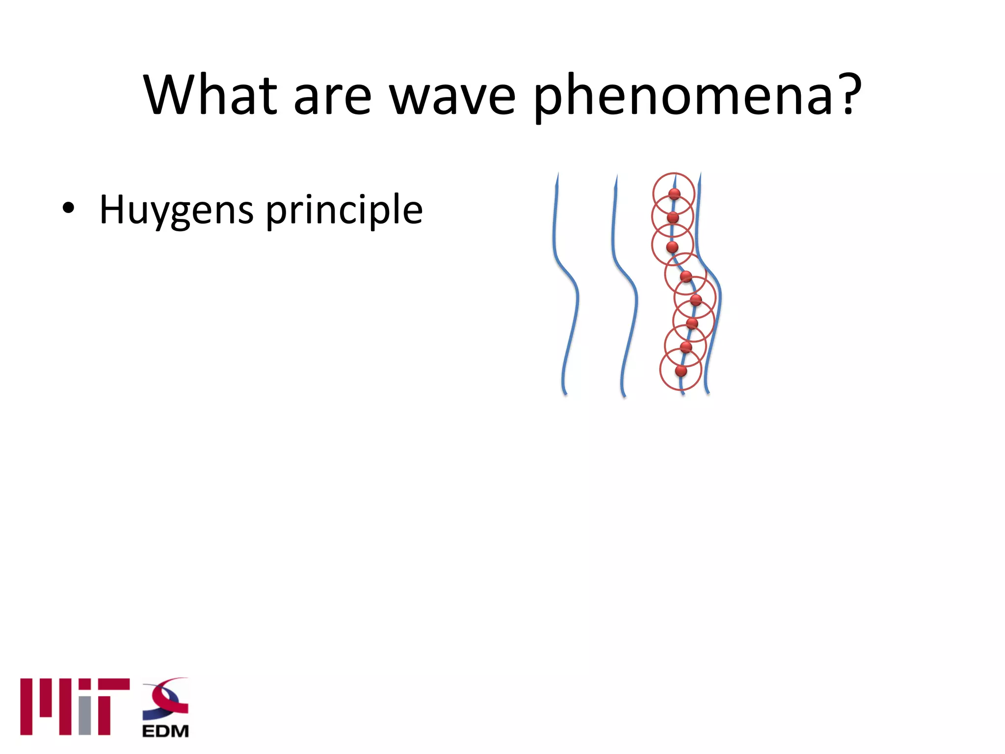
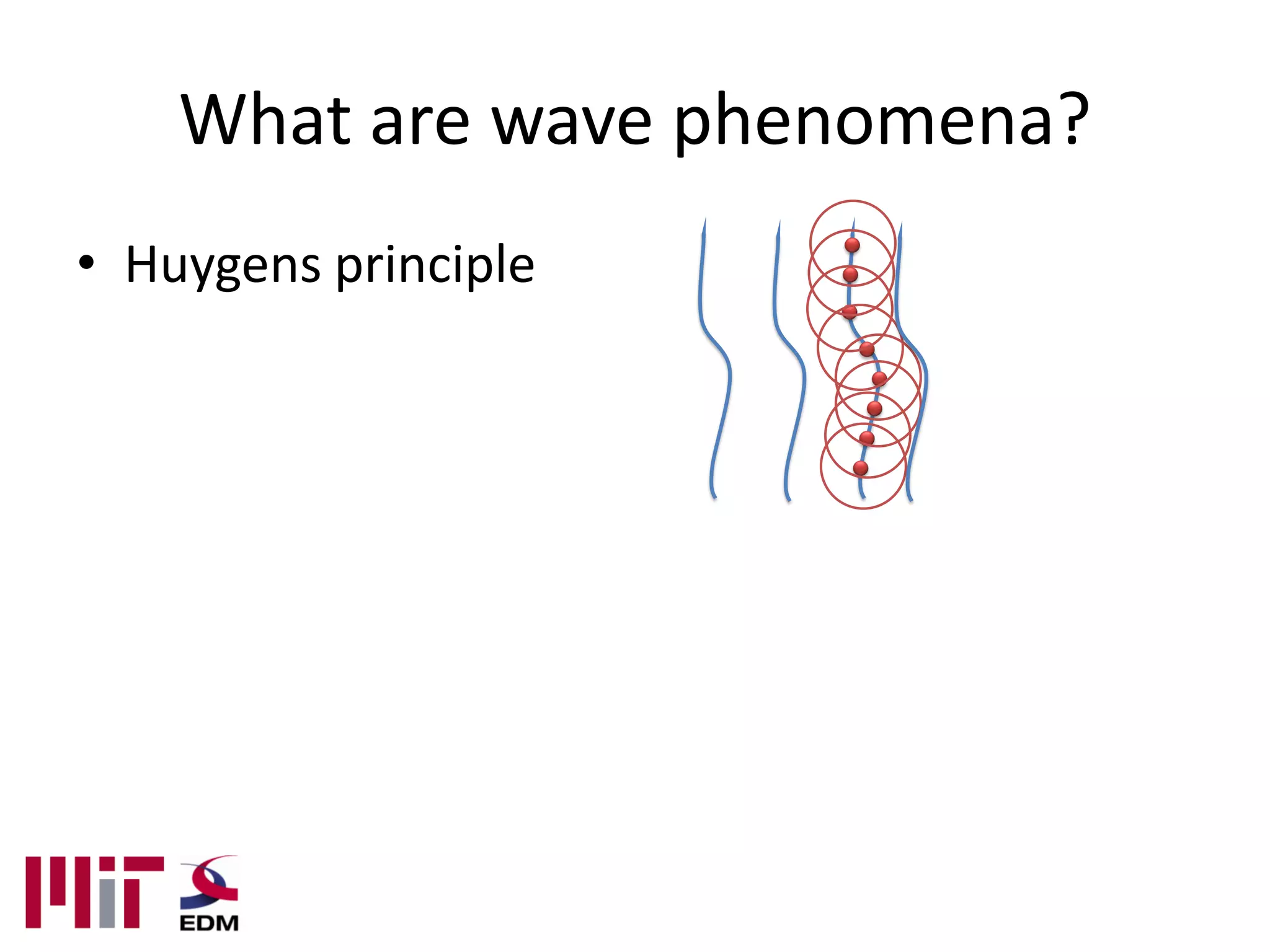
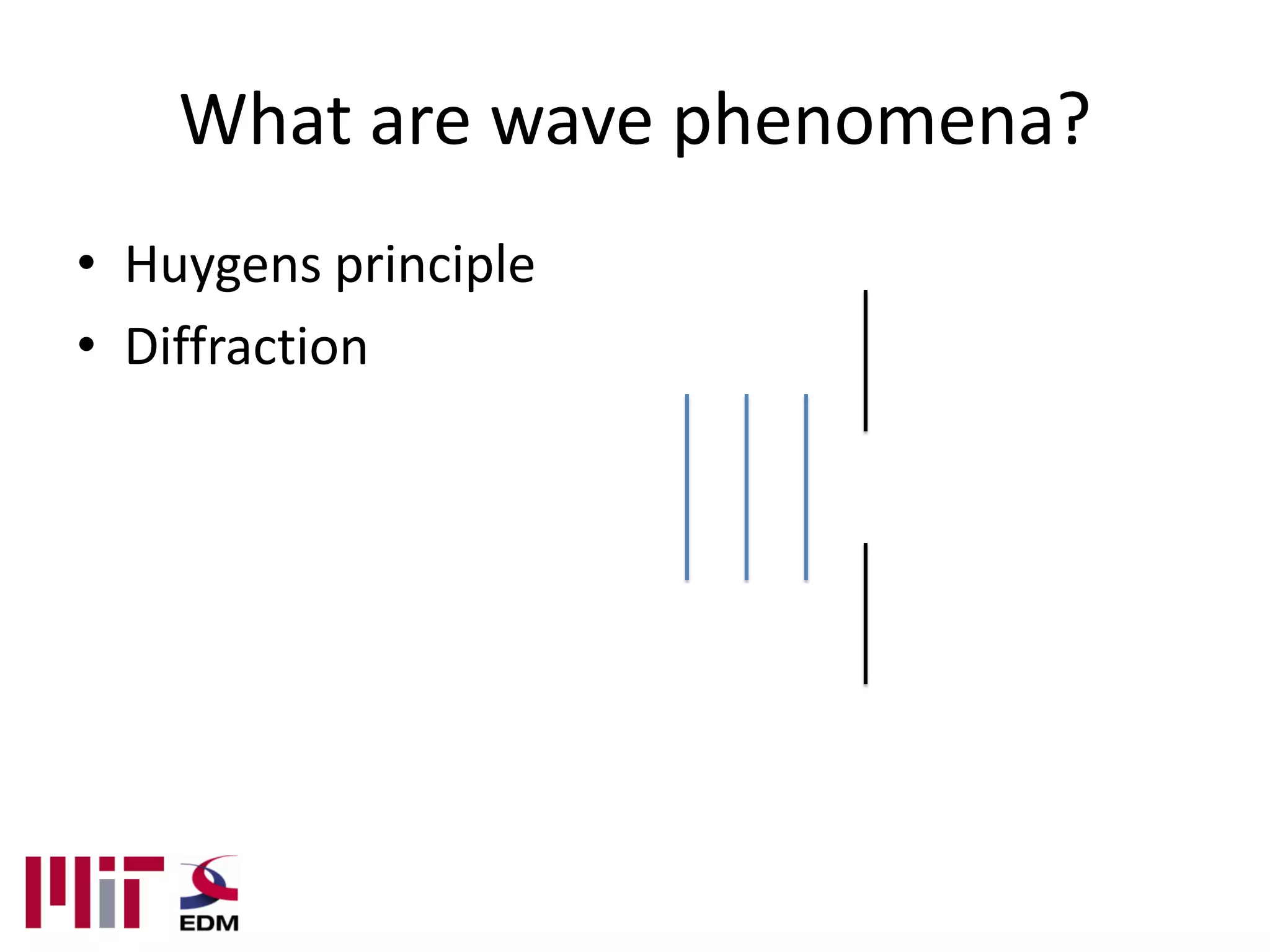
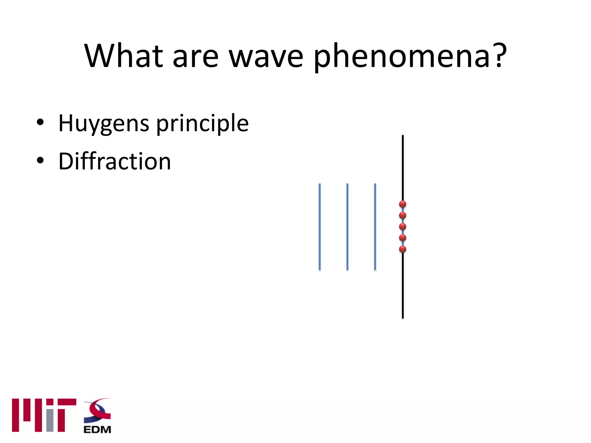
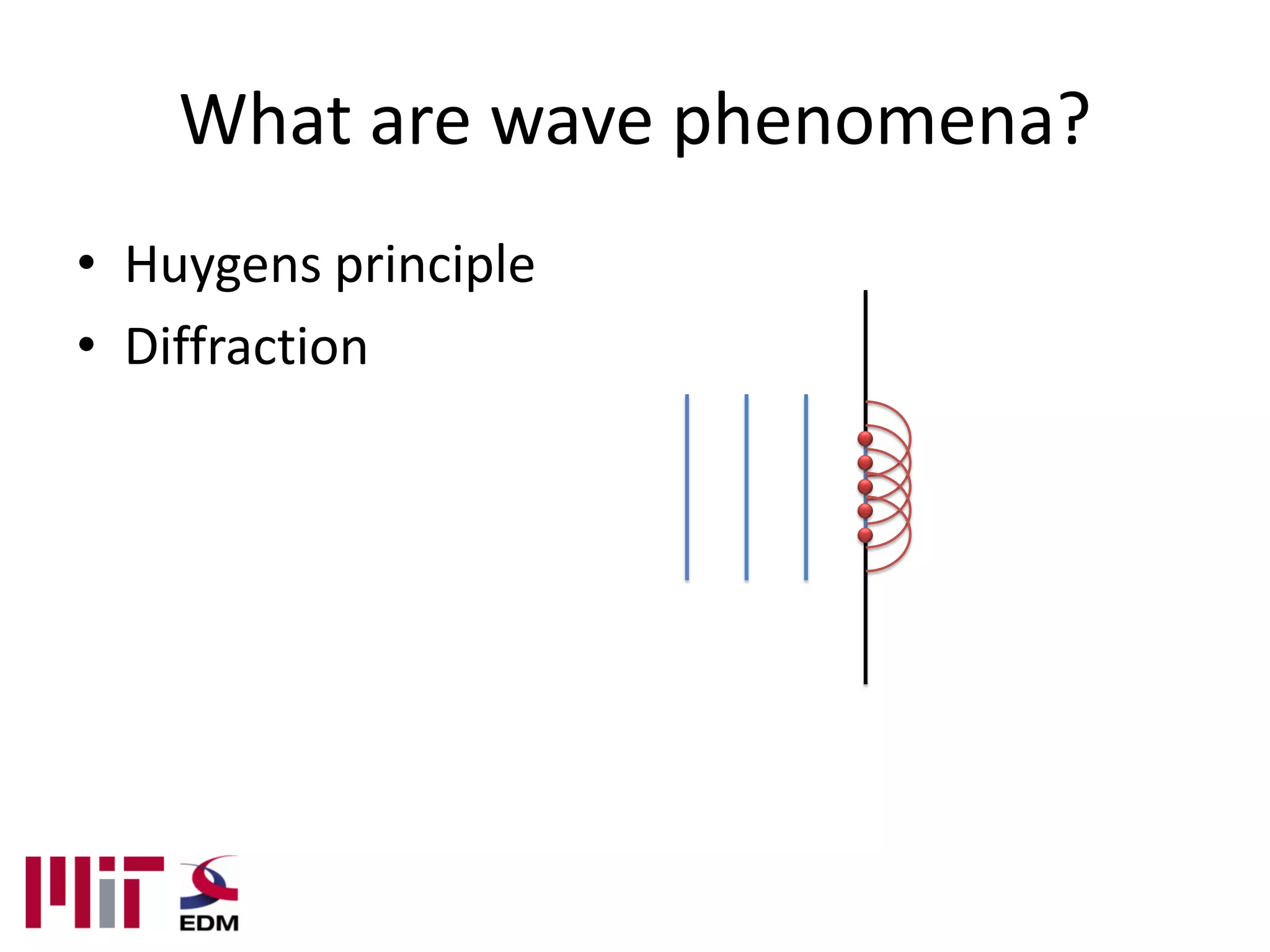
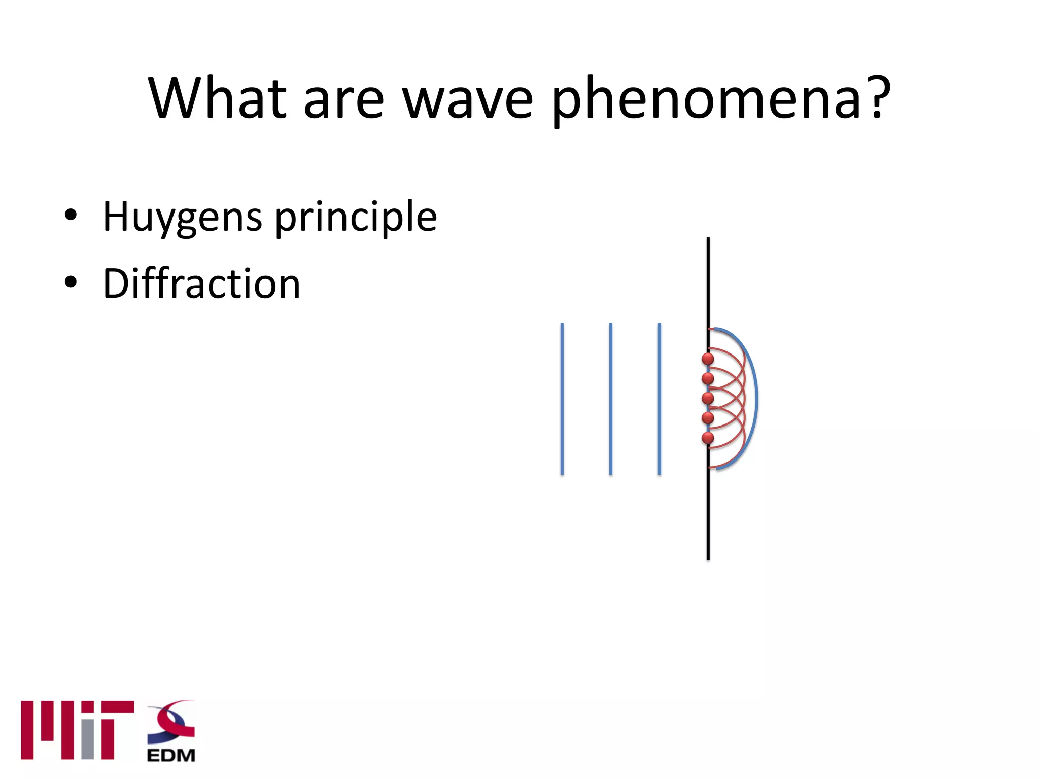
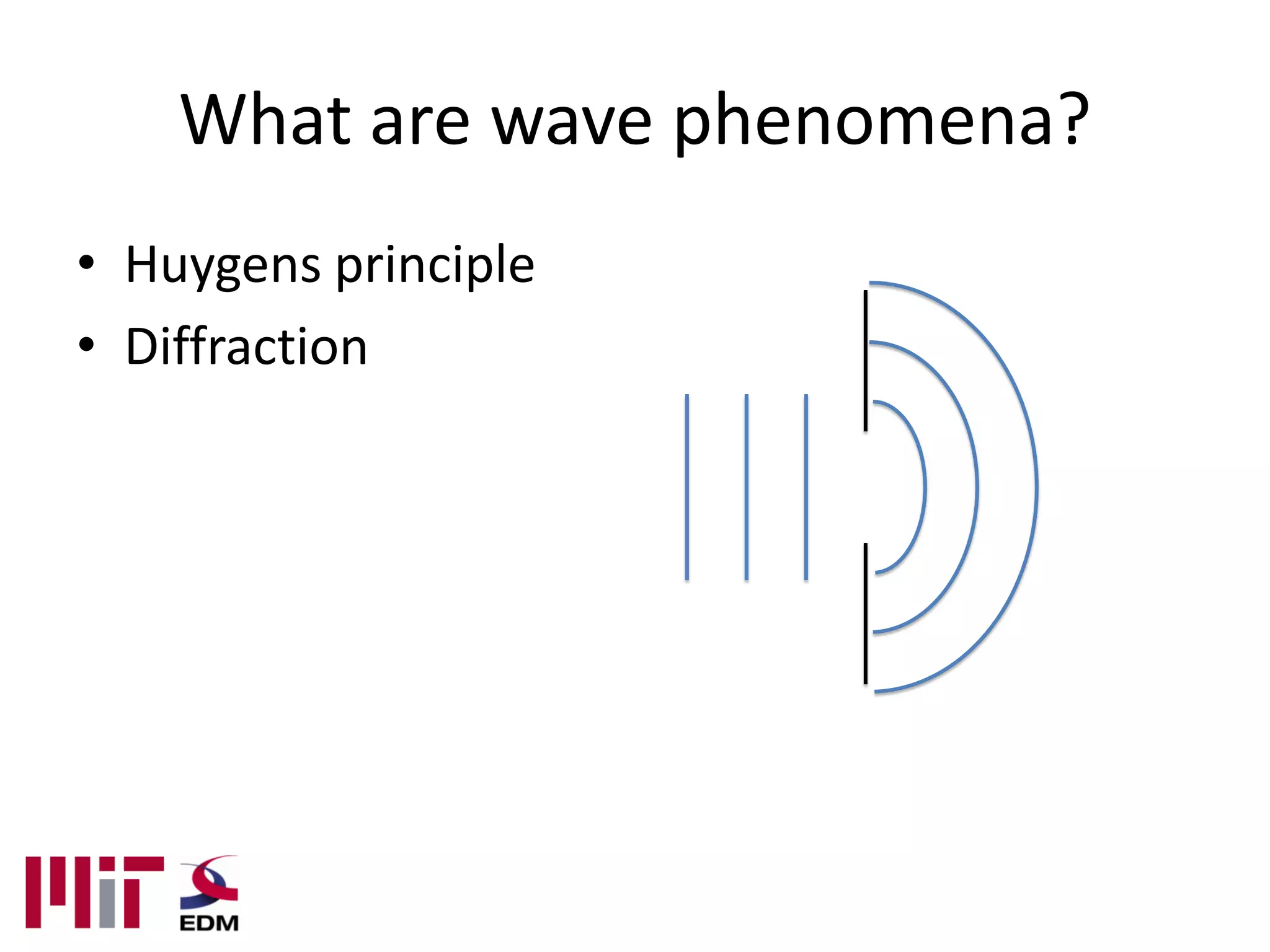
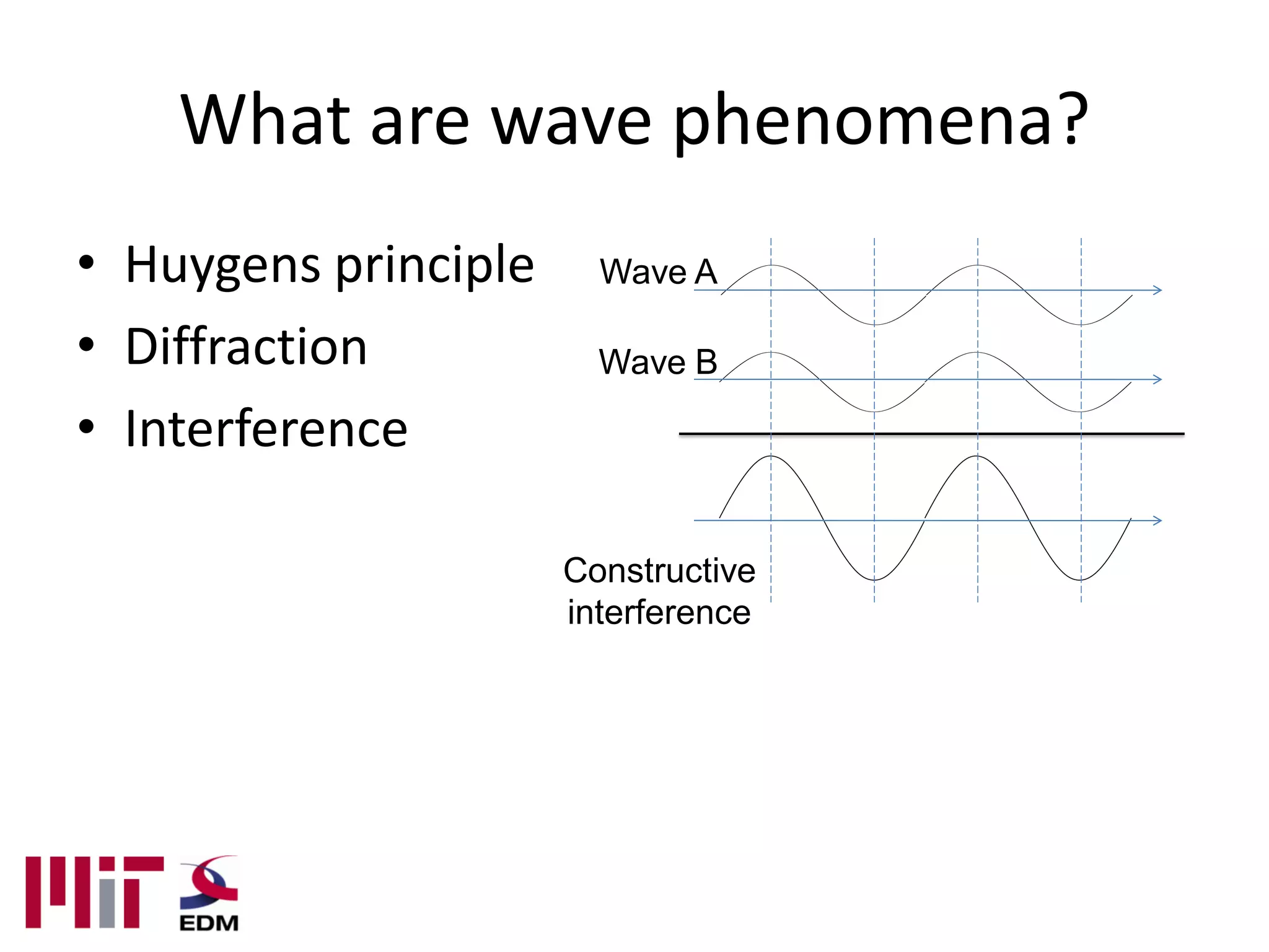
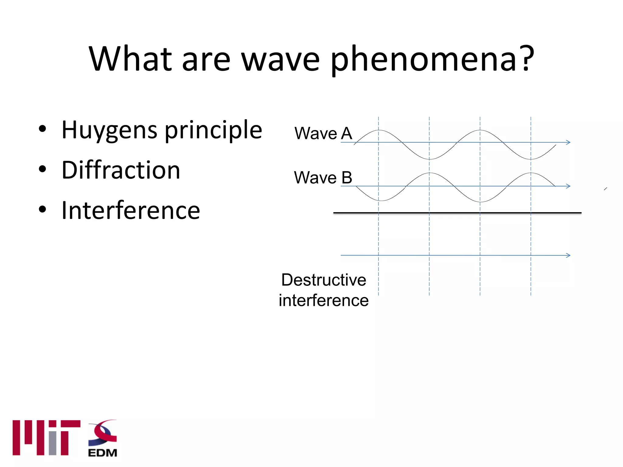
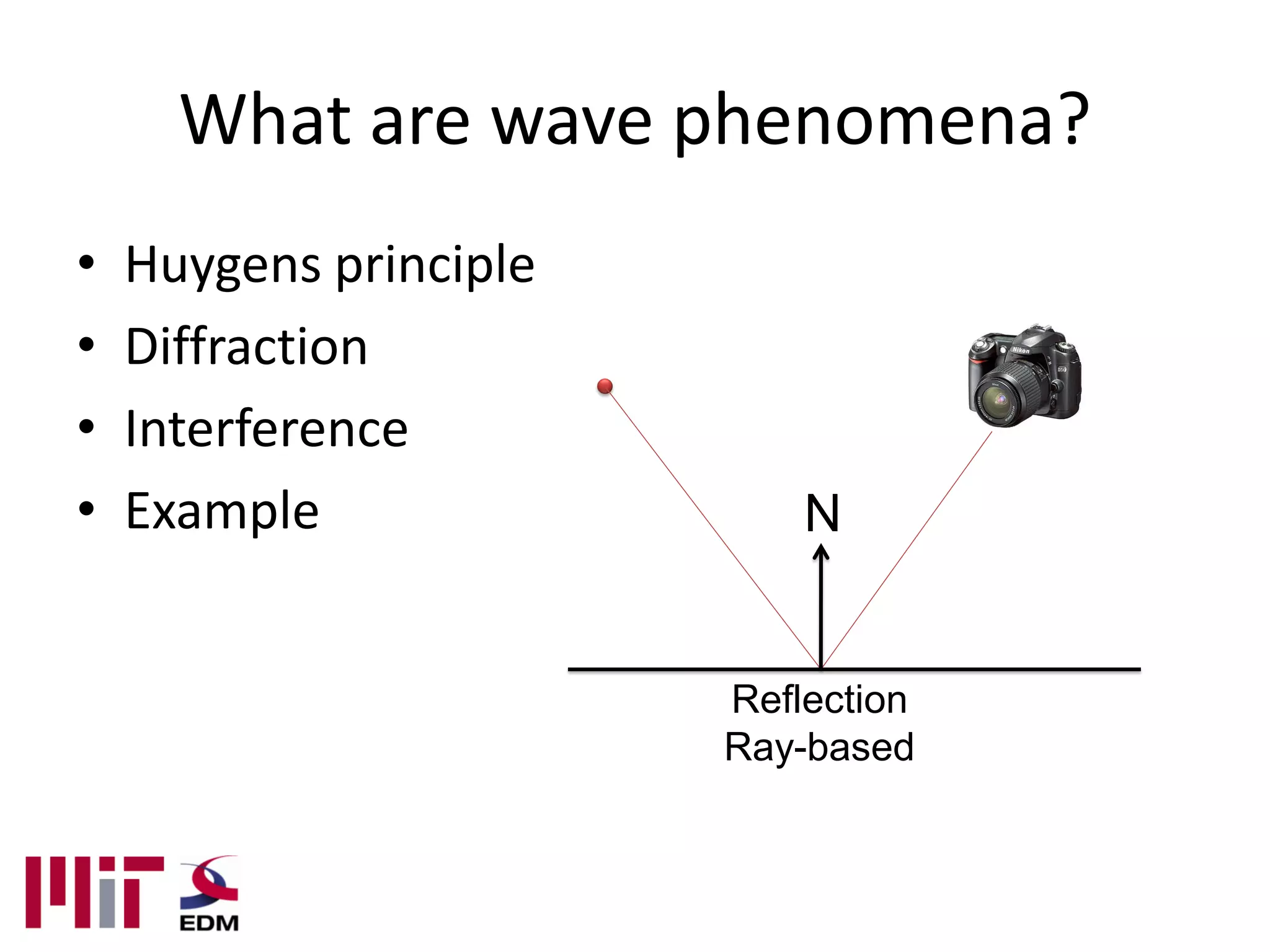
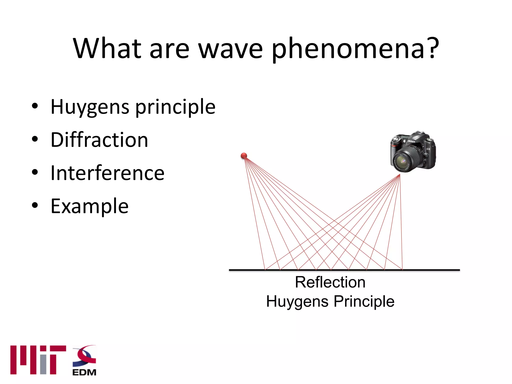
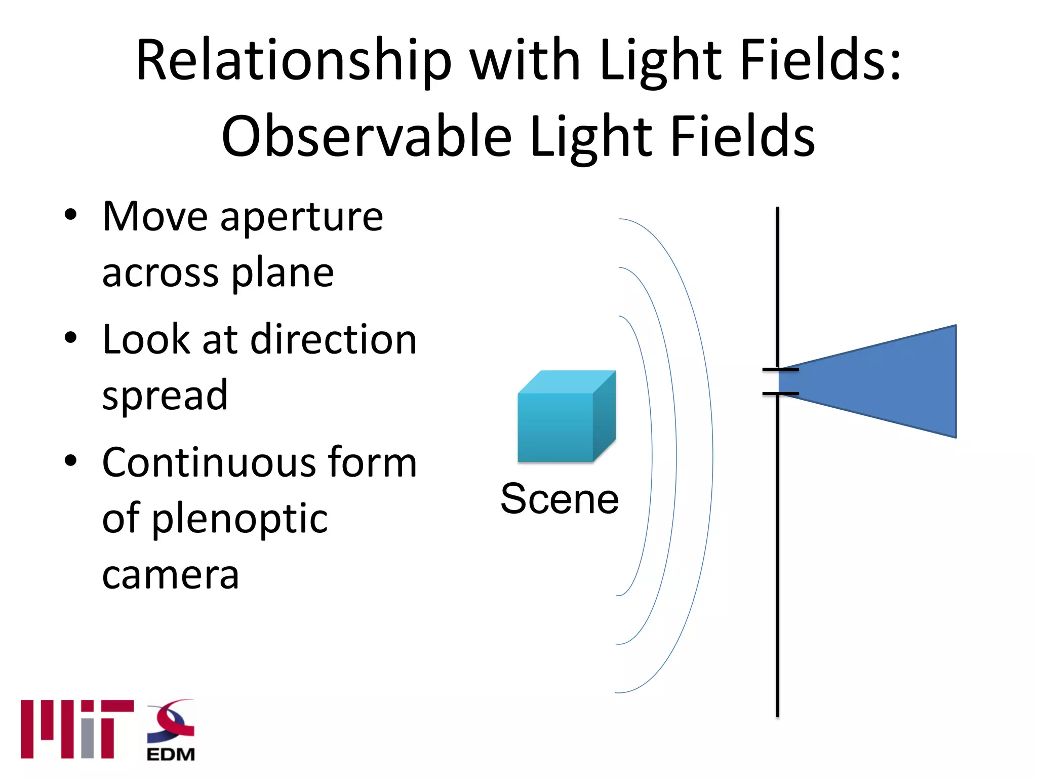
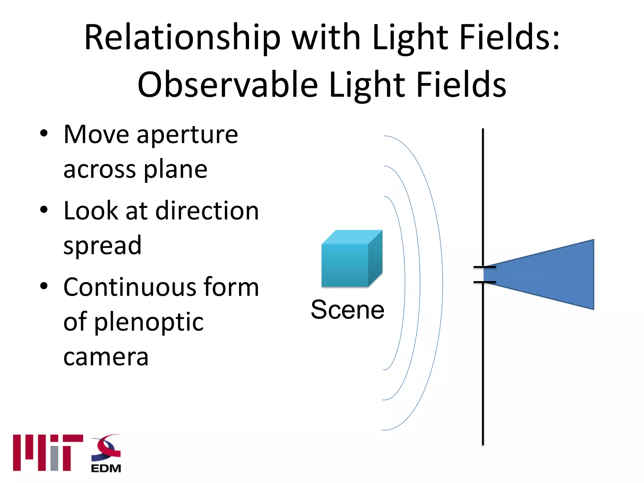
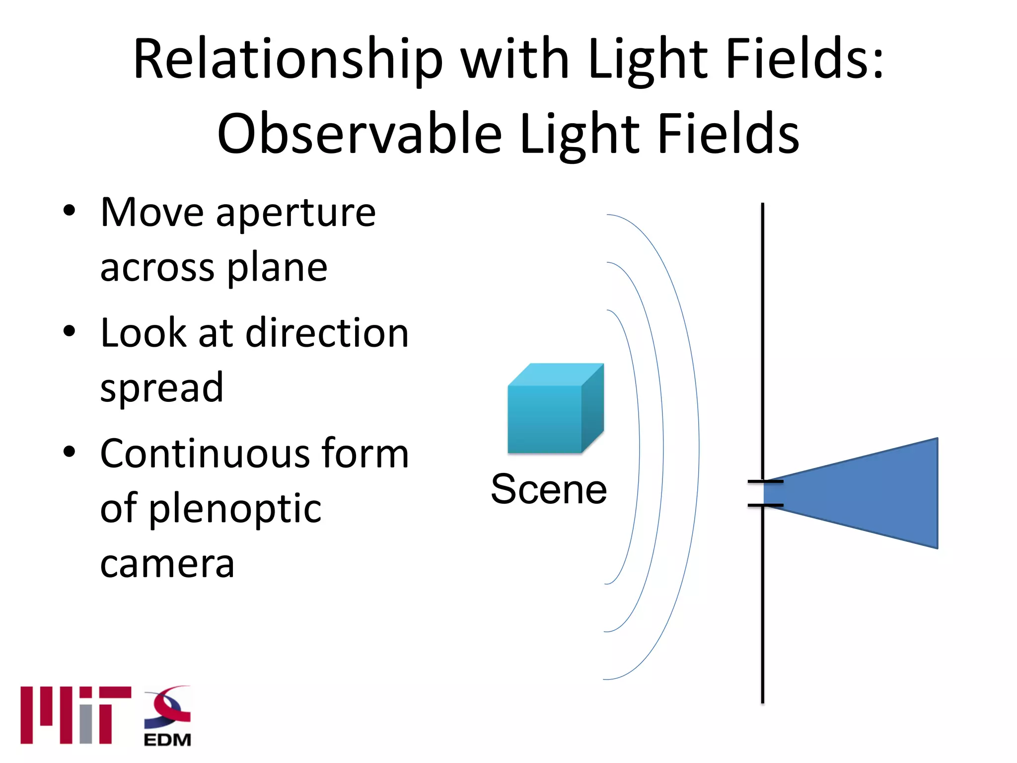
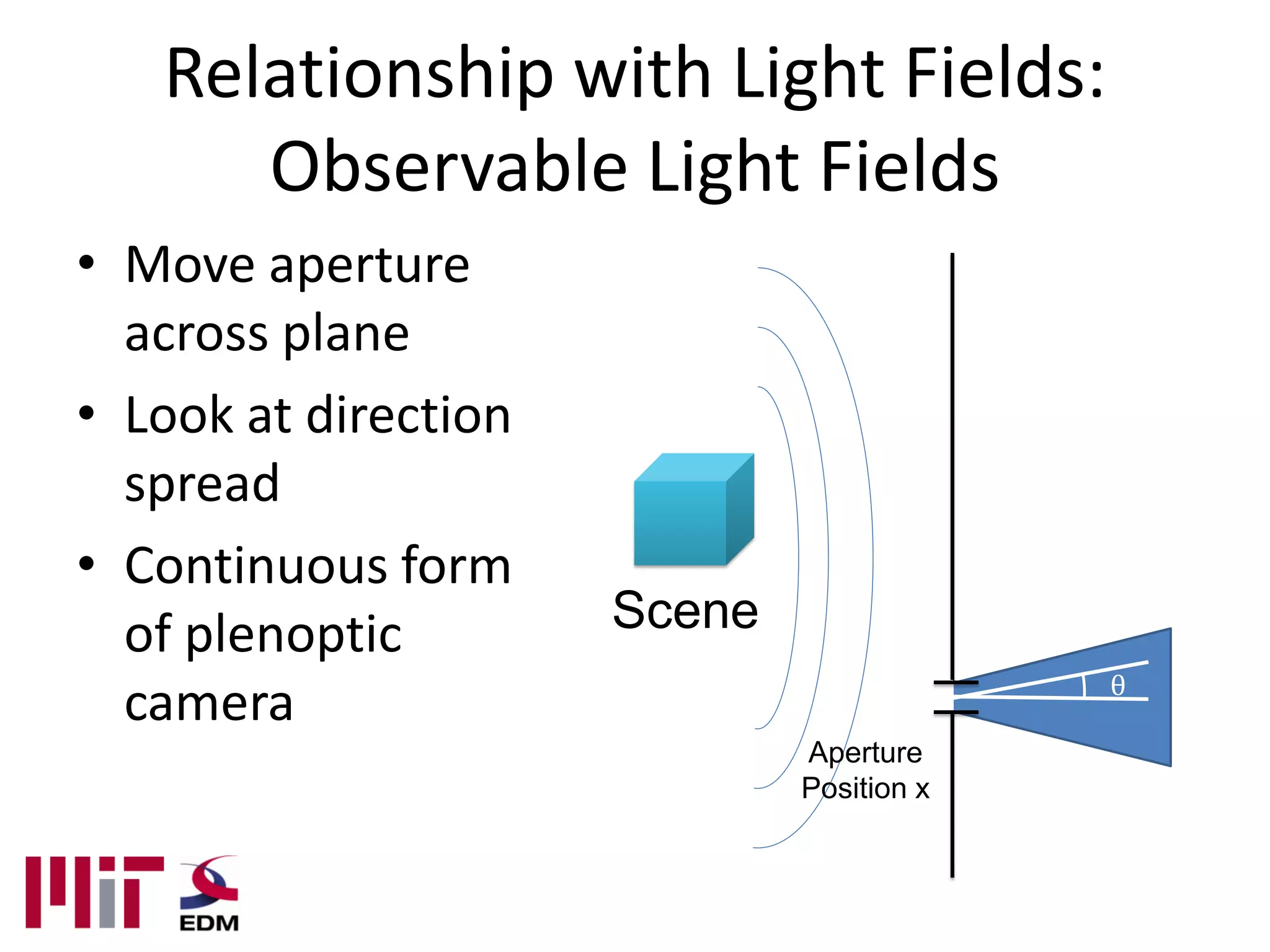
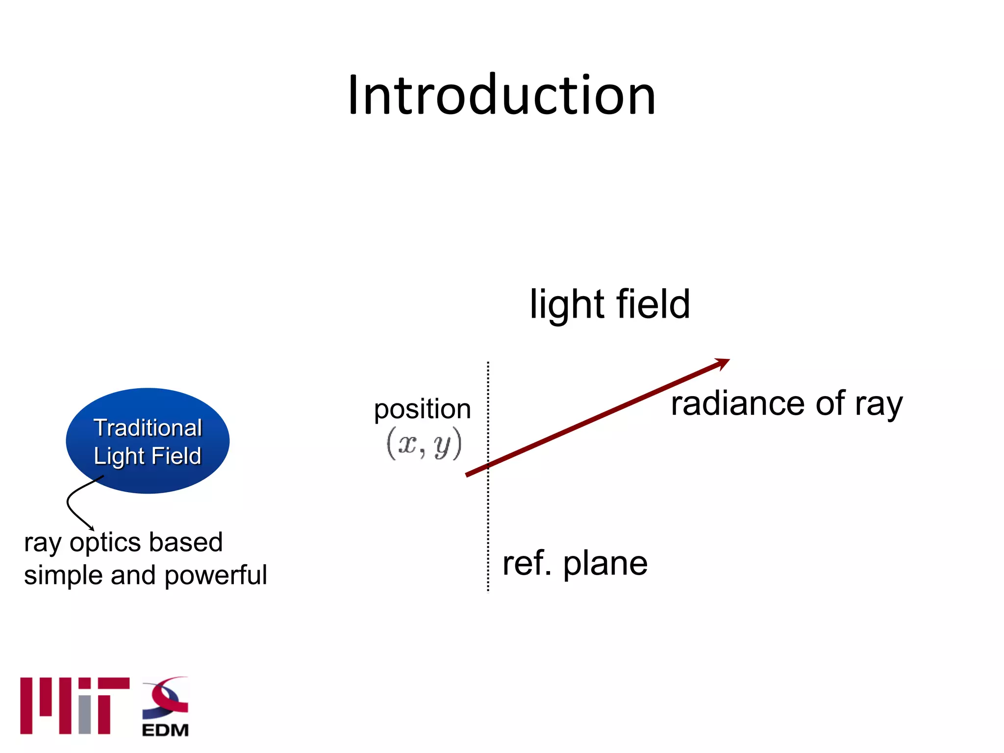
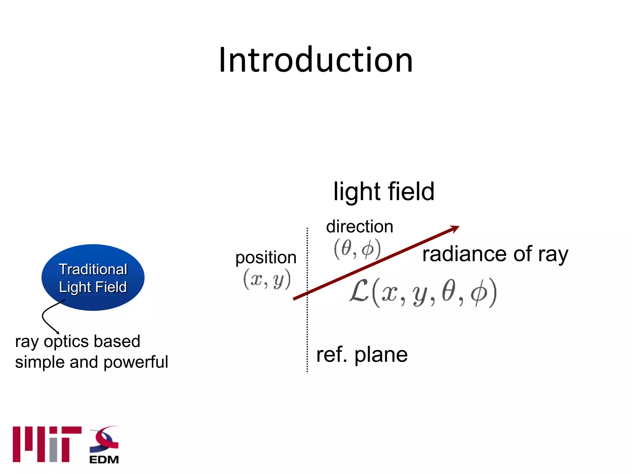
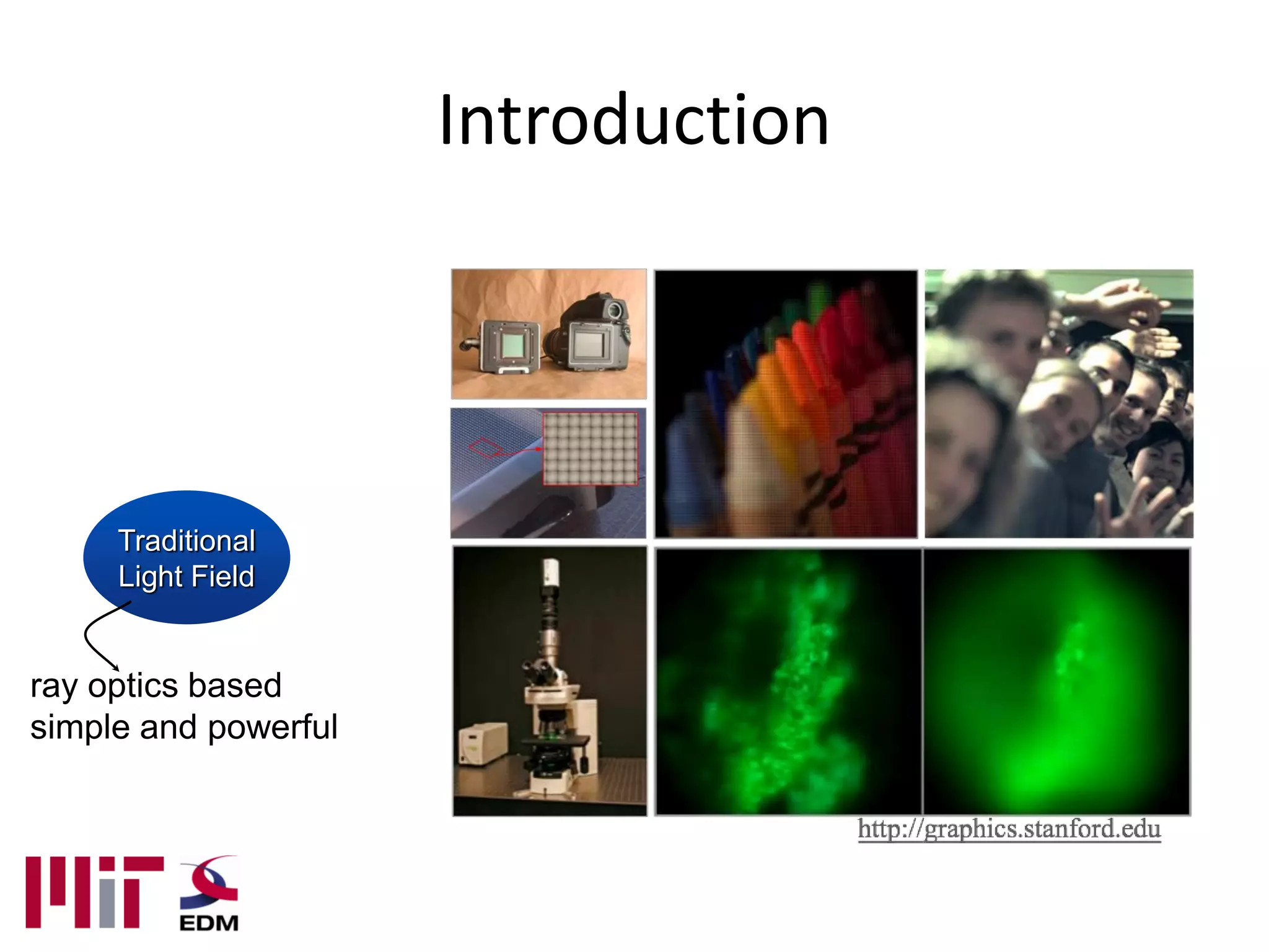
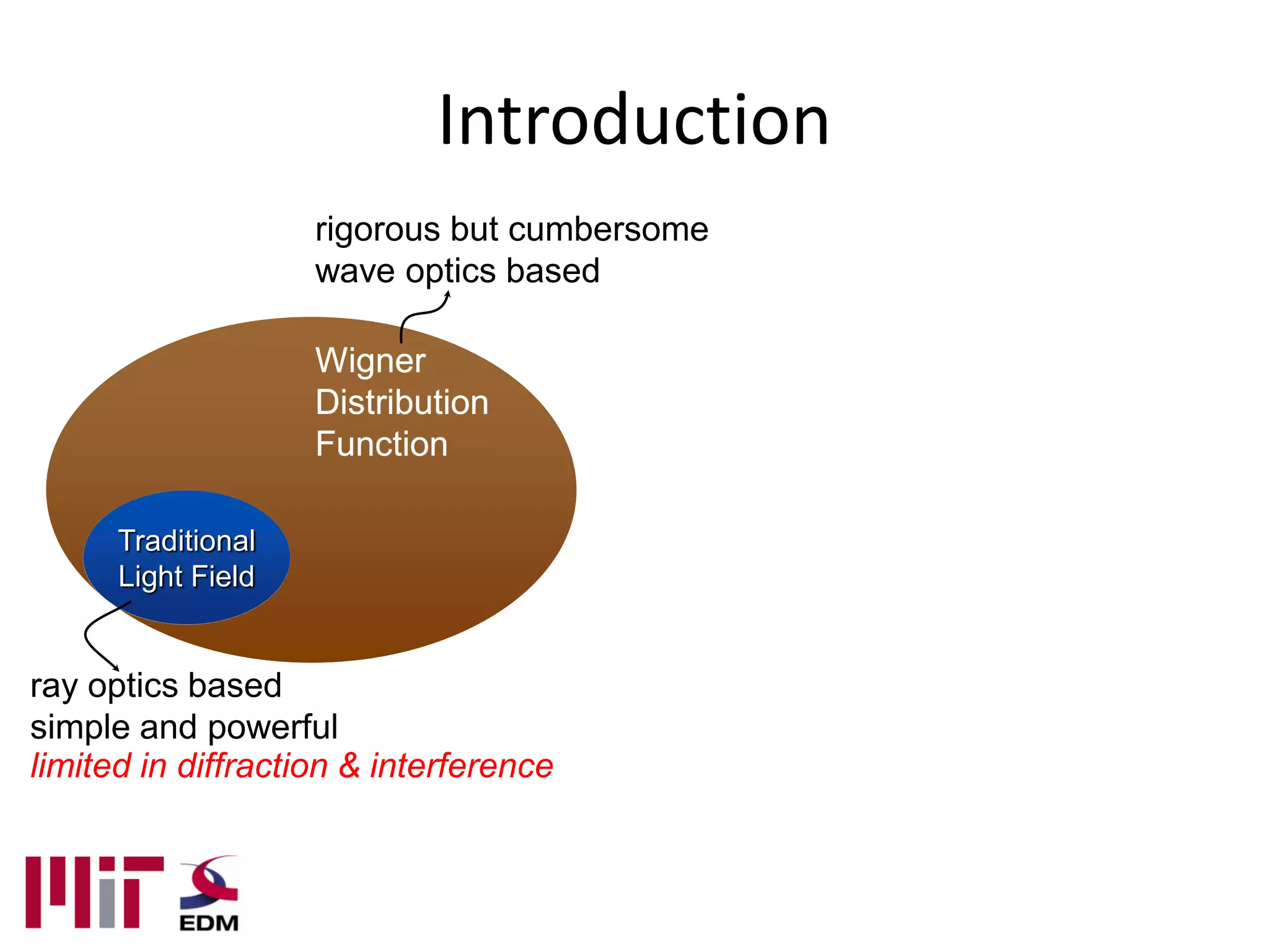
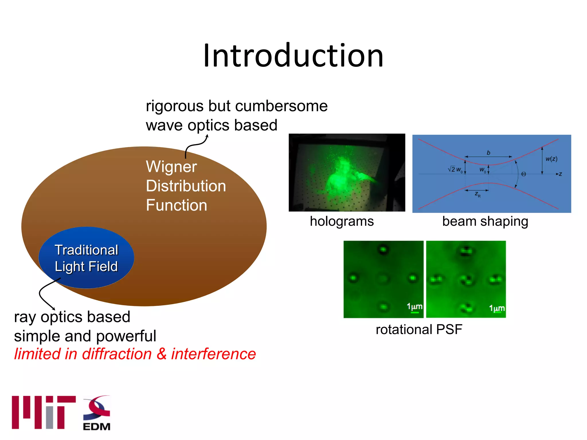
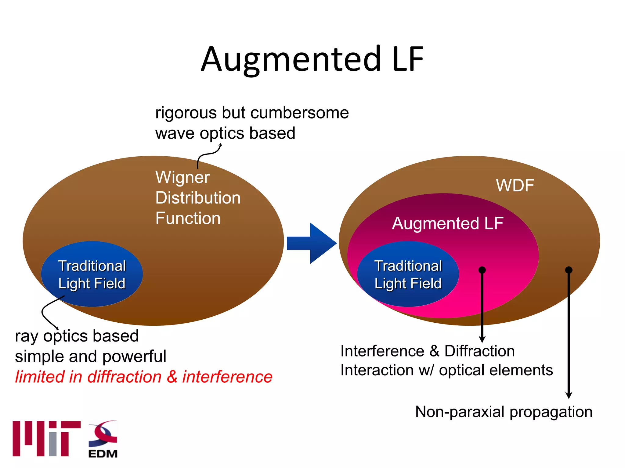
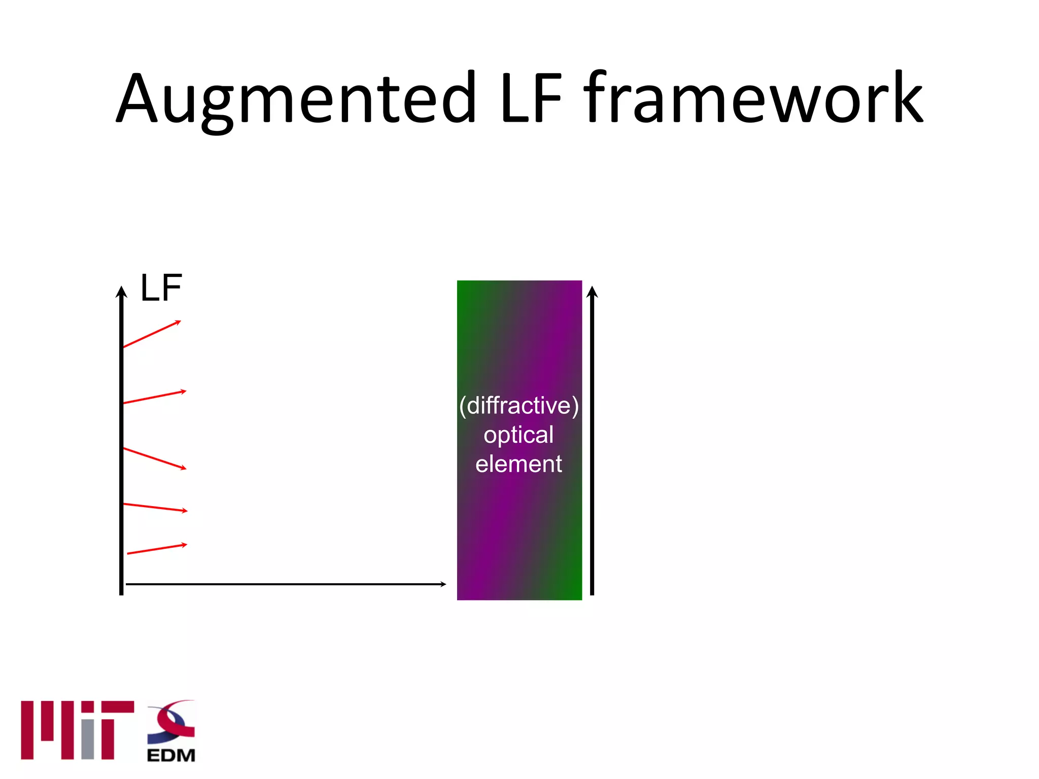
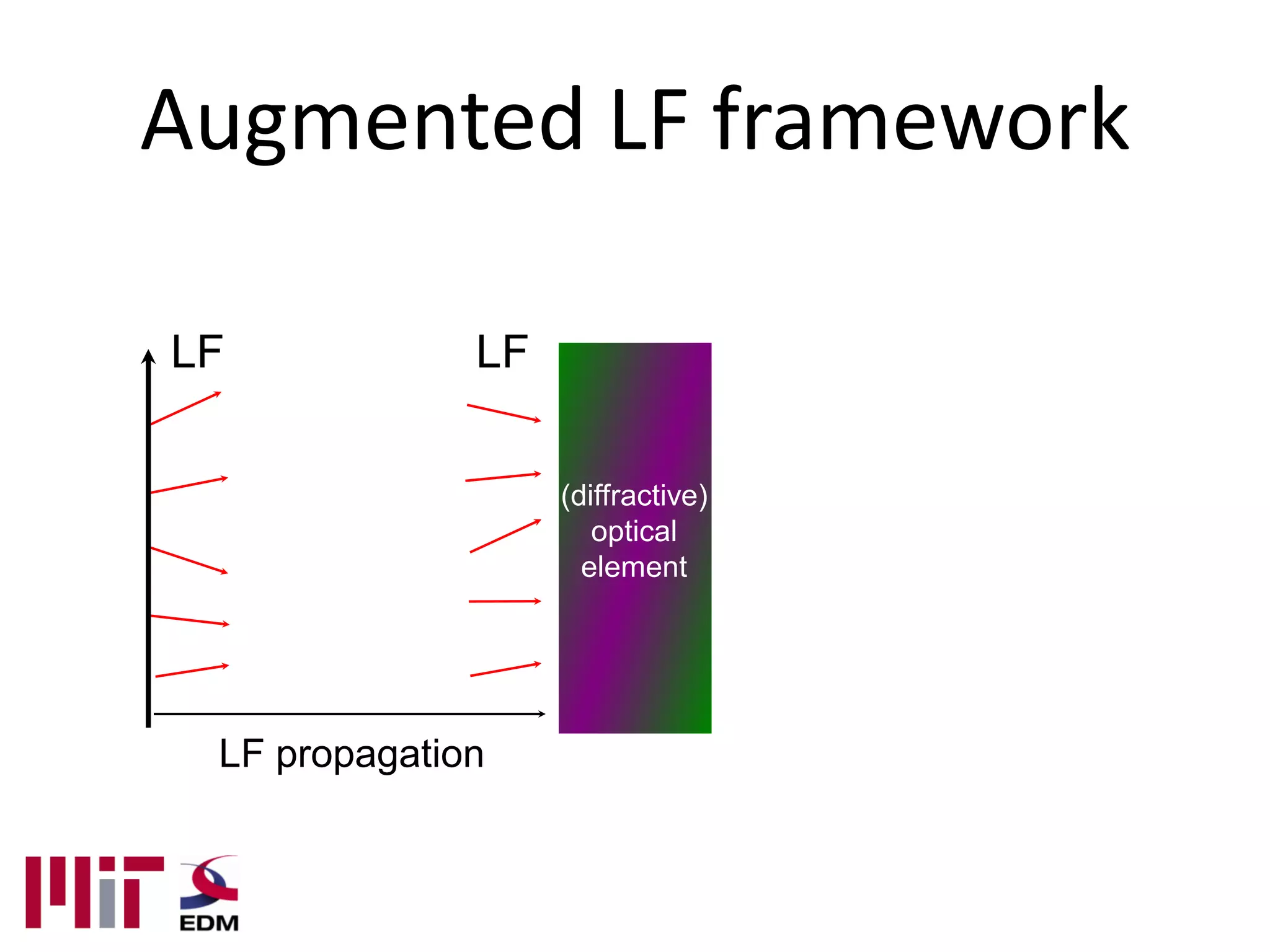
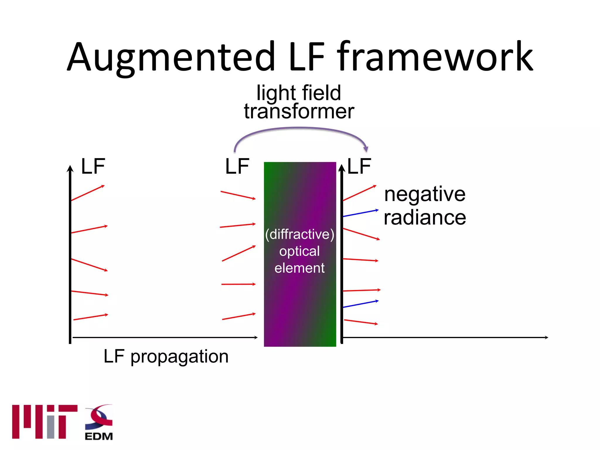
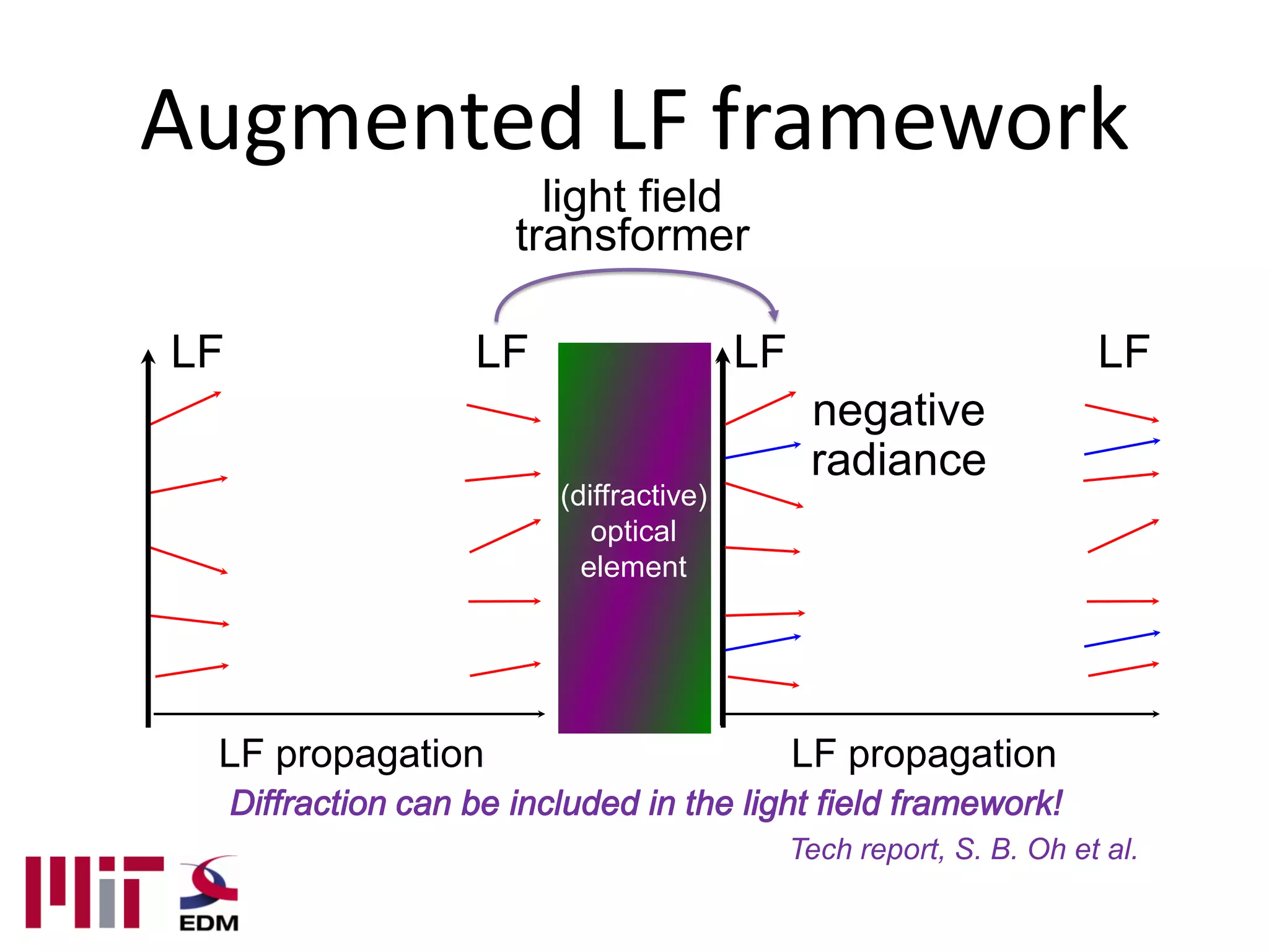
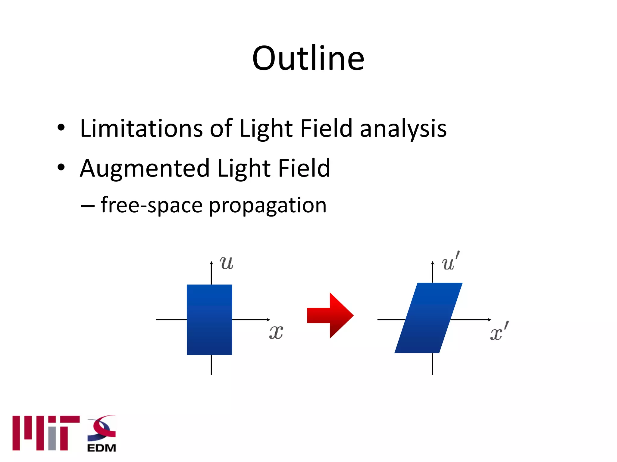
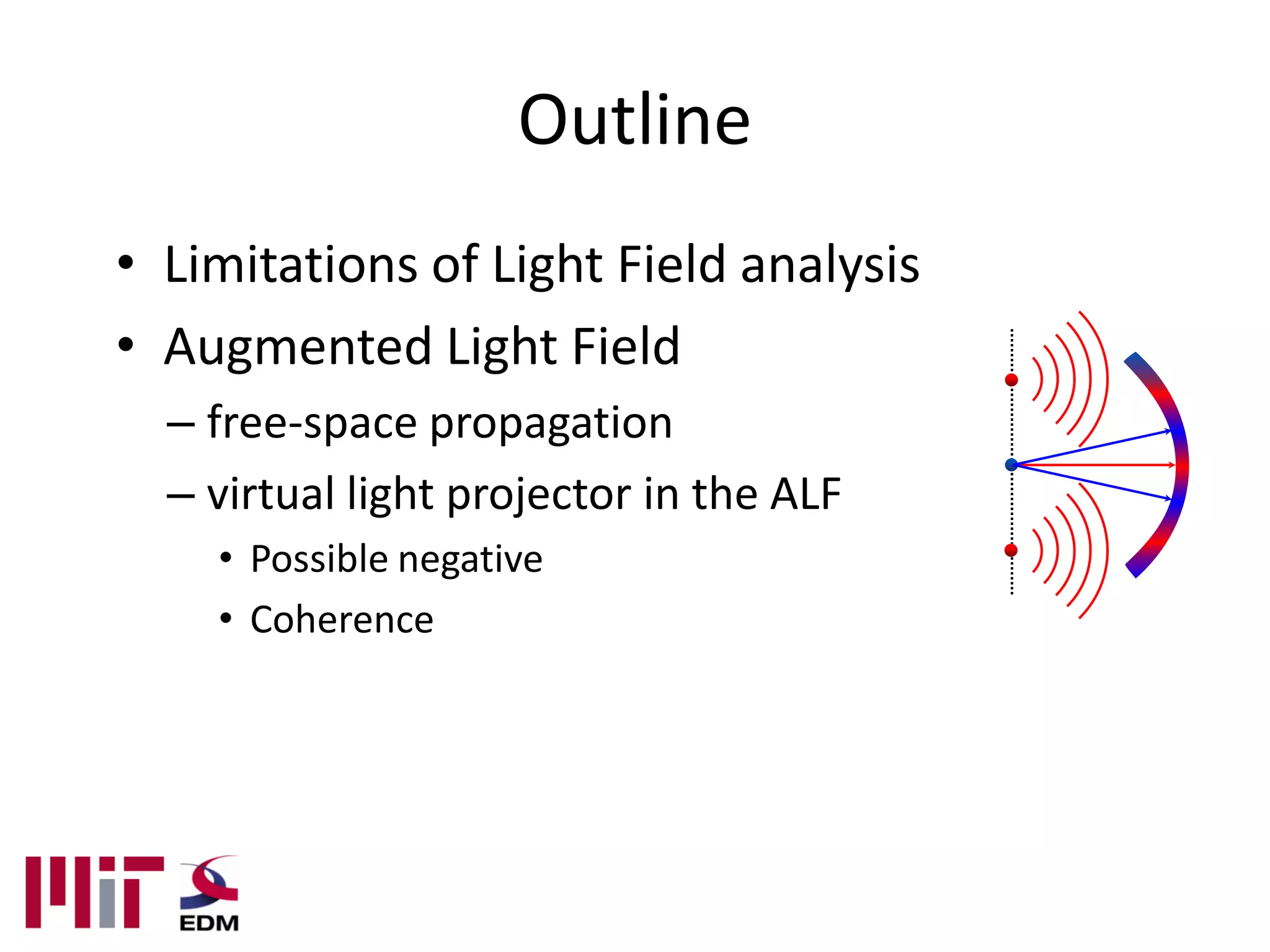
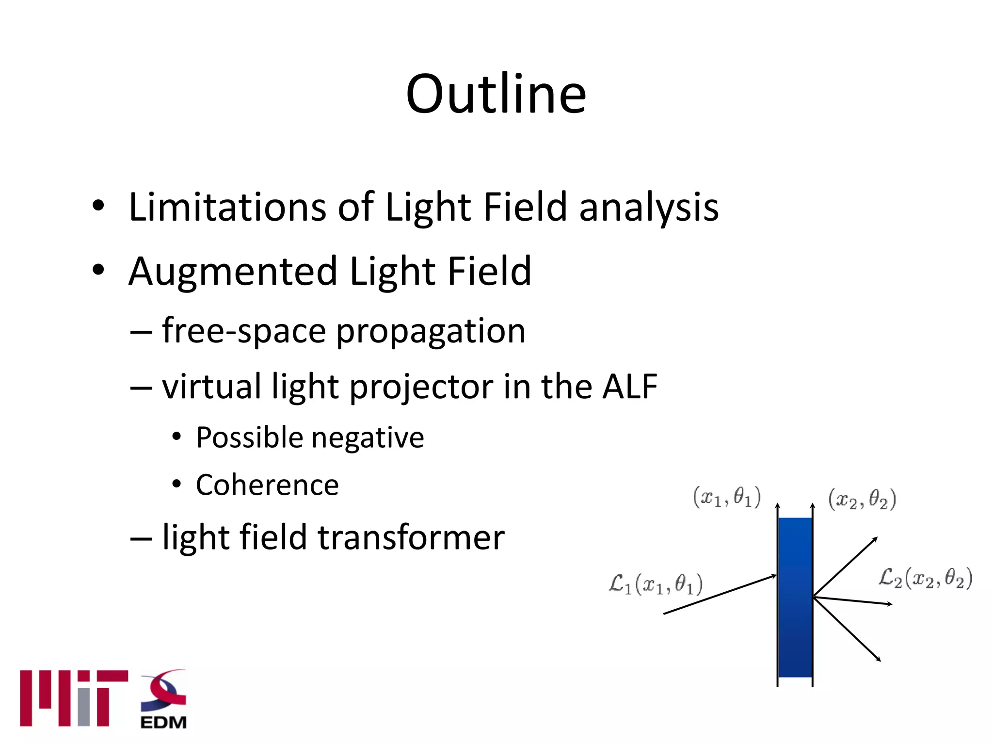
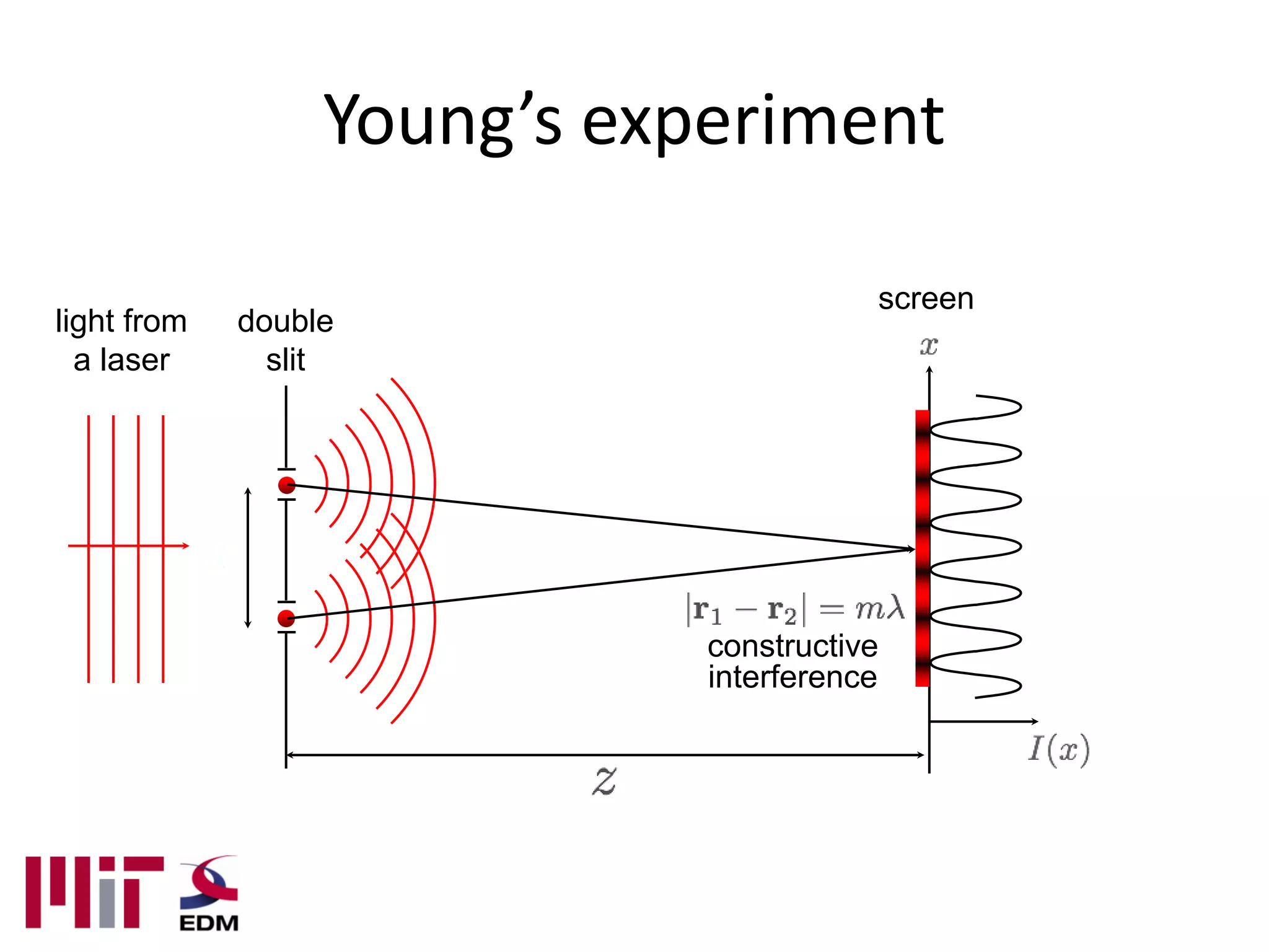
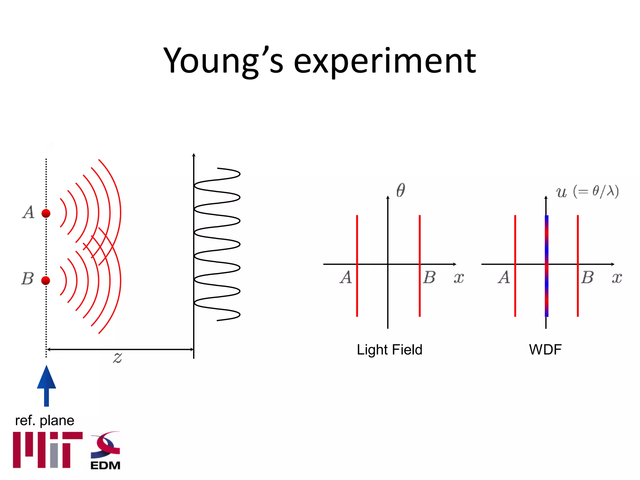
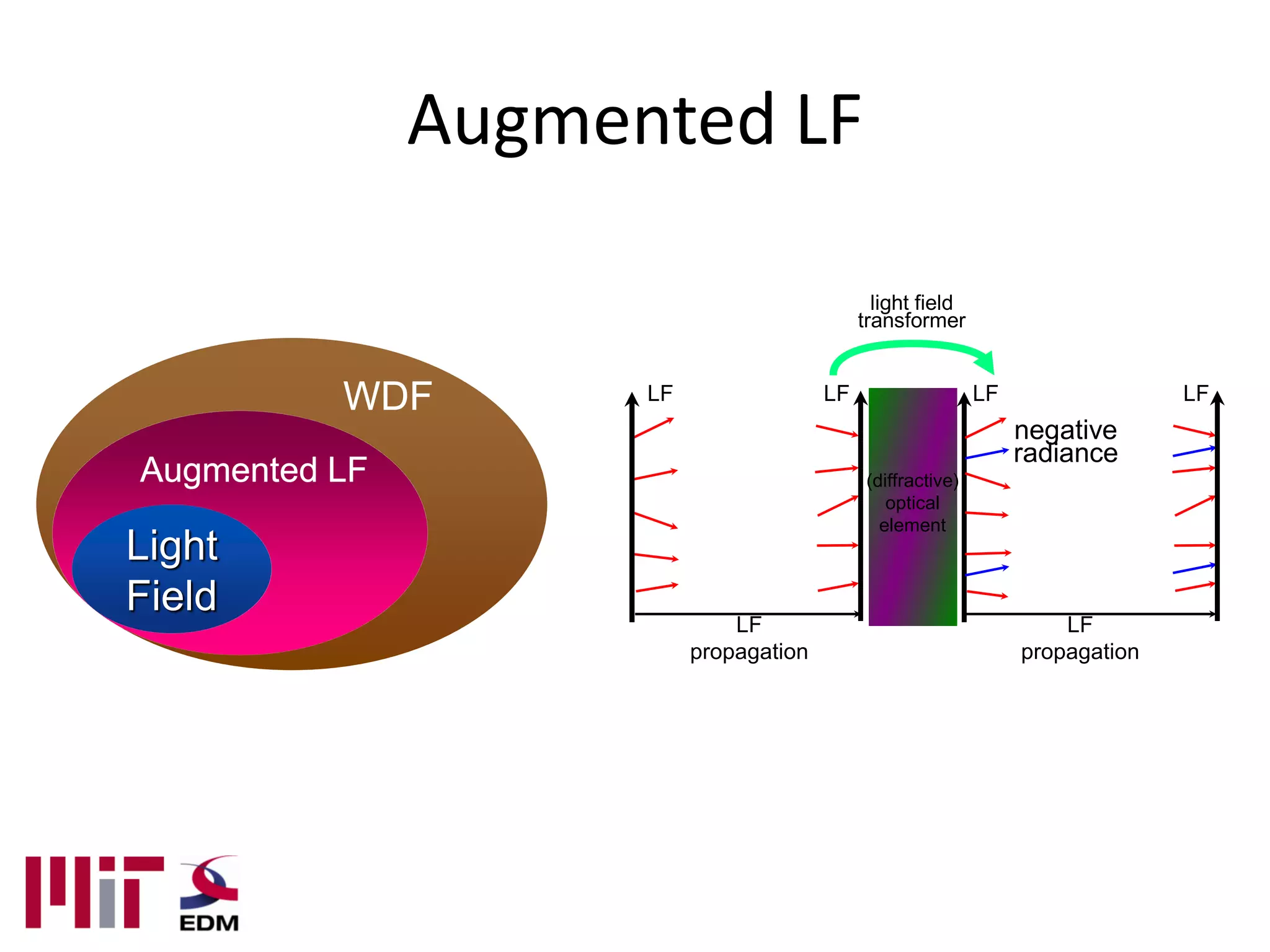
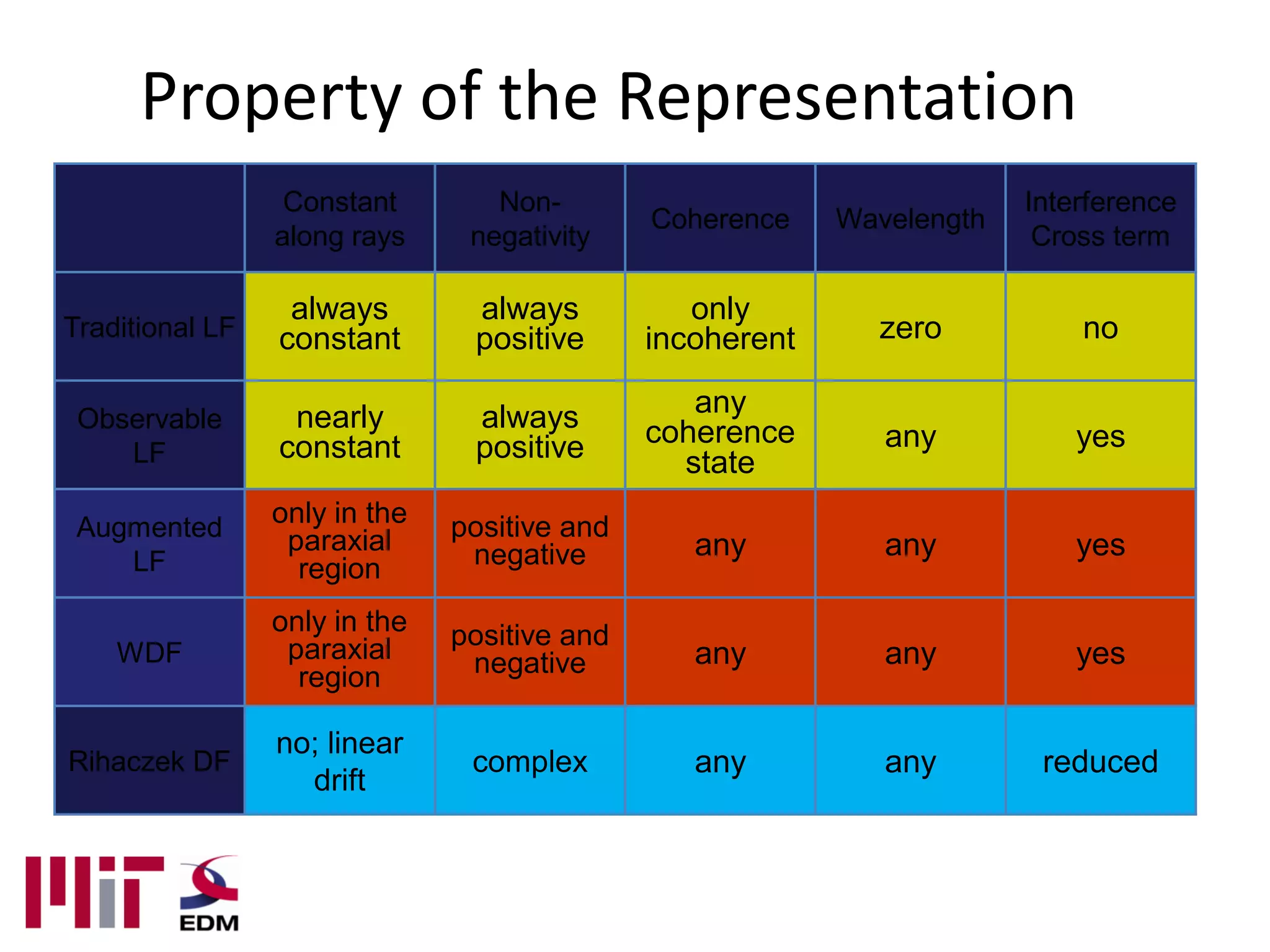
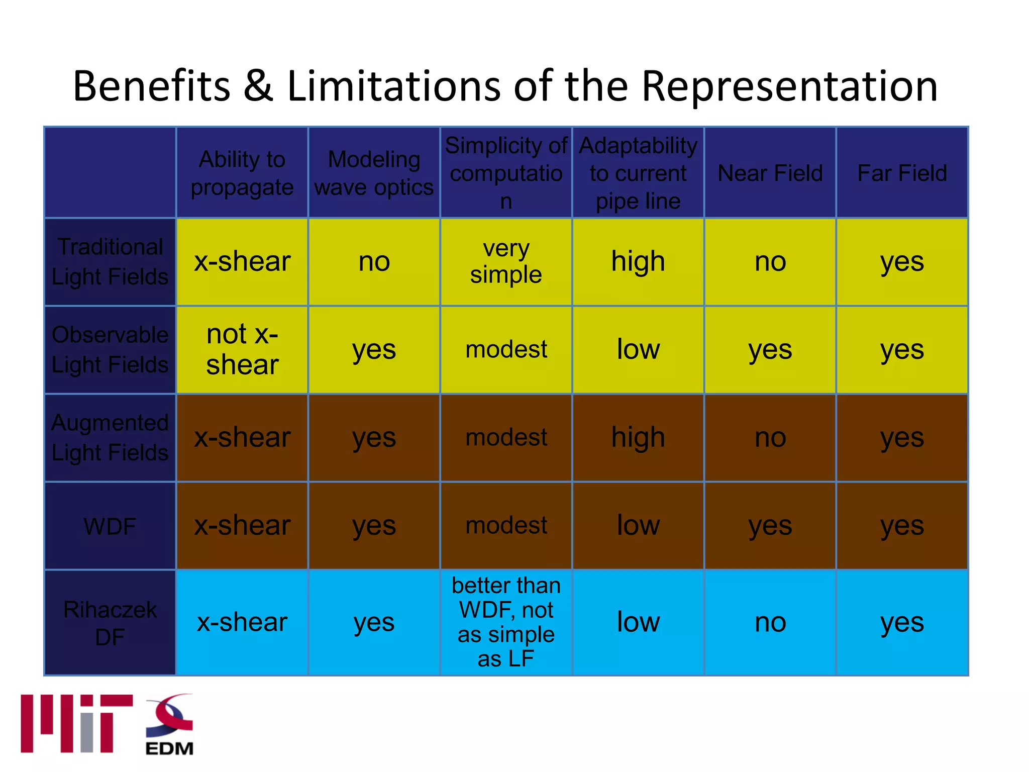
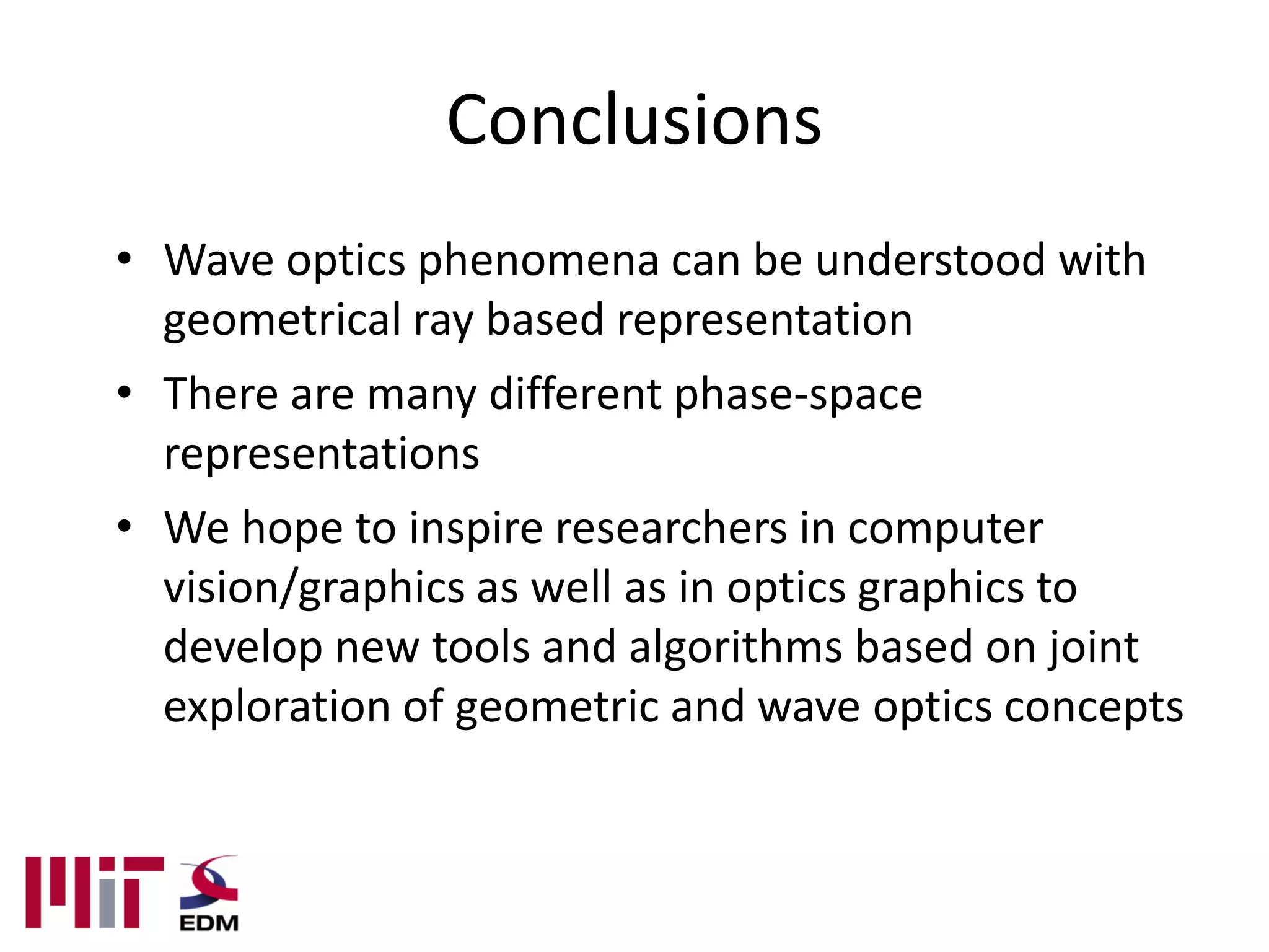
3. Overview
1. Introduction and Welcome
2. Relating wave propagation to Light Fields
3. Augmented Light Fields
4. Applications in Imaging
4. Motivation
• Dual representation of light:
– Photons travelling in a straight line
Computational Photography Computer Graphics
http://graphics.stanford.edu/projects/lightfield
http://graphics.ucsd.edu/~henrik/images
5. Motivation
• Dual representation of light:
– Photons travelling in a straight line
– Waves traveling in all directions
Optics Holography
http://www.humanproductivitylab.com/images
6. Motivation
• Dual representation of light:
– Photons travelling in a straight line
– Waves traveling in all directions
• Goal of the course:
Provide a gentle introduction of wave
phenomenon using ray-based representations
7. Wave phenomena in the real world
• Fluid surfaces
http://4.bp.blogspot.com/_NpINLHeo8rM/Rsl52vjOKII/AAAAAAAAFMM/WnESejvzq5Y/s400/s
plash-water-waves-4559.JPG
8. Wave phenomena in the real world
• Fluid surfaces
• Sound waves
http://fetch1.com/wp-content/uploads/2009/11/hd-800_detail_sound-waves1.jpg
9. Wave phenomena in the real world
• Fluid surfaces
• Sound waves
• Electromagnetic waves
– Microscopic scale
http://upload.wikimedia.org/wikipedia/commons/archive/1/1f/20090127195426!Ggb_in_soap_bubble_1.jpg
10. Coherence
• Degree of making interference
– coherent ⇐ partially coherent ⇒ incoherent
• Correlation of two points on wavefront
– (≈phase difference)
Coherent: deterministic phase relation
Incoherent: uncorrelated phase
relation
11. Coherence
• throwing stones......
single point source many point sources
⇒ coherent ⇒ if thrown identically, still coherent!
⇒ if thrown randomly, then incoherent!
14. What is a wave?
• Types
– Electromagnetic waves
– Mechanical Waves
http://en.wikipedia.org/wiki/File:EM_spectrum.svg
15. What is a wave?
• Types
– Electromagnetic waves
– Mechanical Waves
http://www.gi.alaska.edu/chaparral/acousticspectrum.jpg
16. What is a wave?
• Types λ
• Properties A
– Wavelength: λ
– Frequency : p=0
p=π/2
– Phase: p p=π
p=3π/2
– Amplitude: A
– Polarization
http://www.ccrs.nrcan.gc.ca/glossary/images/3104.gif
36. Introduction
• Review of Light Fields
• Review of Waves using Fourier optics
principles ? (intro)
• Introduction to the Wigner Distribution
Function
• Augmented Light Fields to represent wave
phenomena
37. Plenoptic Function
• Q: What is the set of all things that we can ever see?
• A: The Plenoptic Function (Adelson & Bergen)
Let’s start with a stationary person and try to parameterize
everything that he can see…
38. Gray Snapshot
• P(θ,φ) is intensity of light
– Seen from a single view point
– At a single time
– Averaged over the wavelengths of the visible spectrum
• (can also do P(x,y), but spherical coordinate are nicer)
39. Color Snapshot
P(θ,φ,λ) is intensity of light
– Seen from a single view point
– At a single time
– As a function of wavelength
41. Holographic Movie
P(θ,φ,λ,t,Vx, Vy, Vz) is intensity of light
• – Seen from ANY single view point
• – Over time
• – As a function of wavelength
42. Plenoptic Function
P(θ,φ,λ,t,Vx, Vy, Vz)
• Can reconstruct every possible view, at every moment, from every position,
at every wavelength
• Contains every photograph, every movie, everything that anyone has ever
seen.
48. Why Study Light Fields Using Wave Optics?
z=z0 θ
x
Light
z=0 Field
Macro
Micro f
z=z0
x
Wigner
z=0 Distribution
49. Wave Optics
• Waves instead of rays Parallel rays Plane waves
• Interference & diffraction
• Plane of point emitters
(Huygen’s principle)
• Each emitter has amplitude
and phase
53. Wigner Distribution Function
Auto correlation of complex wavefront
• Input: one-dimensional function of position
• Output: two-dimensional function of position
and spatial frequency
• (some) information about spectrum at each
position
55. 2D Wigner Distribution
• Projection along
frequency yields power
• Projection along position
yield spectral power
f W(x,f)
x
56. 2D Wigner Distribution
|h(x)|² • Projection along
frequency yields power
x • Projection along position
yield spectral power
f W(x,f)
x
57. 2D Wigner Distribution
|h(x)|² • Projection along
frequency yields power
x • Projection along position
yield spectral power
f W(x,f) f
|f(x)|²
x
58. 2D Wigner Distribution
|h(x)|² • Projection along
frequency yields power
x • Projection along position
yield spectral power
f W(x,f) f
|f(x)|²
x
59. 2D Wigner Distribution
Remarks:
• Possible negative values
• Uncertainty principle
f W(x,f)
x
60. Relationship with Light Fields:
Observable Light Fields
• Move aperture
across plane
• Look at direction
spread
• Continuous form
of plenoptic Scene
camera
61. Relationship with Light Fields:
Observable Light Fields
• Move aperture
across plane
• Look at direction
spread
• Continuous form
of plenoptic Scene
camera
62. Relationship with Light Fields:
Observable Light Fields
• Move aperture
across plane
• Look at direction
spread
• Continuous form
of plenoptic Scene
camera
63. Relationship with Light Fields:
Observable Light Fields
• Move aperture
across plane
• Look at direction
spread
• Continuous form
of plenoptic Scene
camera
64. Relationship with Light Fields:
Observable Light Fields
• Move aperture
across plane
• Look at direction
spread
• Continuous form
of plenoptic Scene
camera
65. Relationship with Light Fields:
Observable Light Fields
• Move aperture
across plane
• Look at direction
spread
• Continuous form
of plenoptic Scene
camera
66. Relationship with Light Fields:
Observable Light Fields
• Move aperture
across plane
• Look at direction
spread
• Continuous form
of plenoptic Scene
θ
camera
Aperture
Position x
68. Relationship with Light Fields:
Observable Light Fields
Aperture Window Power
Wave Fourier Transform
69. Relationship with Light Fields:
Observable Light Fields
Aperture Window Power
Wave Fourier Transform
70. Relationship with Light Fields:
Observable Light Fields
Aperture Window Power
Wave Fourier Transform
Wigner Distribution Wigner Distribution
of wave function of aperture window
71. Relationship with Light Fields:
Observable Light Fields
Blur trades off
resolution in position
with direction
Wigner Distribution Wigner Distribution
of wave function of aperture window
72. Relationship with Light Fields:
Observable Light Fields
At zero wavelength limit
(regime of ray optics)
Wigner Distribution
of wave function
73. Relationship with Light Fields:
Observable Light Fields
At zero wavelength limit
(regime of ray optics)
Observable light field and Wigner equivalent!
74. Observable Light Field
• Observable light field is a blurred Wigner
distribution with a modified coordinate
system
• Blur trades off resolution in position with
direction
• Wigner distribution and observable light field
equivalent at zero wavelength limit
75. Light Fields and Wigner
• Observable Light Fields = special case of
Wigner
• Ignores wave phenomena
• Can we also introduce wave phenomena in
light fields?
– -> Augmented Light Fields
77. Introduction
light field
position radiance of ray
Traditional
Light Field
ray optics based
simple and powerful ref. plane
78. Introduction
light field
direction
position radiance of ray
Traditional
Light Field
ray optics based
simple and powerful ref. plane
79. Introduction
Traditional
Light Field
ray optics based
simple and powerful
80. Introduction
rigorous but cumbersome
wave optics based
Wigner
Distribution
Function
Traditional
Light Field
ray optics based
simple and powerful
limited in diffraction & interference
81. Introduction
rigorous but cumbersome
wave optics based
Wigner
Distribution
Function
holograms beam shaping
Traditional
Light Field
ray optics based
rotational PSF
simple and powerful
limited in diffraction & interference
82. Augmented LF
rigorous but cumbersome
wave optics based
Wigner WDF
Distribution
Function Augmented LF
Traditional Traditional
Light Field Light Field
ray optics based
simple and powerful Interference & Diffraction
limited in diffraction & interference Interaction w/ optical elements
Non-paraxial propagation
83. Augmented LF
• Not a new light field
• A new methodology/framework to create,
modulate, and propagate light fields
– stay purely in position-angle space
• Wave optics phenomena can be understood
with the light field
90. Outline
• Limitations of Light Field analysis
• Augmented Light Field
– free-space propagation
– virtual light projector in the ALF
• Possible negative
• Coherence
91. Outline
• Limitations of Light Field analysis
• Augmented Light Field
– free-space propagation
– virtual light projector in the ALF
• Possible negative
• Coherence
– light field transformer
92. Assumptions
• Monochromatic (= temporally coherent)
– can be extended into polychromatic
• Flatland (= 1D observation plane)
– can be extended to the real world
• Scalar field and diffraction (= one polarization)
– can be extended into polarized light
• No non-linear effect (two-photon, SHG, loss,
absorption, etc)
93. Young’s experiment
screen
light from double
a laser slit
constructive
interference
94. Young’s experiment
screen
light from double
a laser slit
destructive
interference
97. Virtual light projector
projection
real projector
negative
virtual light projector positive
at the mid point
real projector
Augmented
LF
intensity=0
Not conflict with physics
98. Virtual light projector
first null
real projector (OPD = λ/2)
virtual light projector
real projector
99. Virtual light projector
hyperbola first null
(OPD = λ/2)
asymptote of
λ/2
hyperbola
valid in Fresnel regime
(or paraxial)
100. Virtual light projector
in high school physics destructive interference
(need negative radiance from
class, virtual light projector)
Video
waves
101. Question
• Does a virtual light projector also work for
incoherent light?
• Yes!
102. Temporal coherence
• Broadband light is incoherent
• ALF (also LF and WDF) can be defined
for different wavelength and treated
independently
106. Spatial coherence
• ALF w/ virtual light projectors is
defined for spatially coherent light
• For partially coherent/incoherent light,
adding the defined ALF still gives valid
results!
110. Young’s Exp. w/ spatially
incoherent light
w/ random
phase
(uncorrelated)
spatially incoherent light:
infinite number of waves propagating along all
the direction with random phase delay
125. Wavefront coding
• ALF of a phase mask(slowly varying ϕ(x))
conventional wavefront coding
extended DOF
(w/ deconvolution)
126. Unusual PSF for depth from
defocus
standard PSF DH PSF
Defocus circle with distance
Prof. Rafael Piestun’s group
Courtesy of S. R. P. Pavani
Univ. of Colorado@Boulder U. of Colorado@Boulder
127. Rotating PSF
• Rotating beams
– Superposition along a straight line
– Rotation rate related to slope of
line
– Both intensity and phase rotate
– Maximum rotation rate in
Rayleigh range
intensity
Courtesy of S. R. P. Pavani
135. Future direction
• Tomography & Inverse problems
• Beam shaping/phase mask design by ray-
based optimization
• New processing w/ virtual light source
136. Space of LF representations
Time-frequency representations
Phase space representations
Quasi light field
Other LF
representations
Observable
LF
WDF
Augmented
LF
Other LF
Traditional
representations light field
incoherent
Rihaczek
Distribution
Function
coherent
137. Property of the Representation
Constant Non- Interference
Coherence Wavelength
along rays negativity Cross term
always always only
Traditional LF constant positive incoherent zero no
Observable nearly always any
constant positive coherence any yes
LF state
Augmented only in the positive and
paraxial negative any any yes
LF region
only in the positive and
WDF paraxial negative any any yes
region
no; linear
Rihaczek DF complex any any reduced
drift
138. Benefits & Limitations of the Representation
Simplicity of Adaptability
Ability to Modeling
computatio to current Near Field Far Field
propagate wave optics
n pipe line
Traditional very
Light Fields
x-shear no simple high no yes
Observable not x-
yes modest low yes yes
Light Fields shear
Augmented
Light Fields
x-shear yes modest high no yes
WDF x-shear yes modest low yes yes
better than
Rihaczek WDF, not
DF
x-shear yes as simple low no yes
as LF
139. Conclusions
• Wave optics phenomena can be understood with
geometrical ray based representation
• There are many different phase-space
representations
• We hope to inspire researchers in computer
vision/graphics as well as in optics graphics to
develop new tools and algorithms based on joint
exploration of geometric and wave optics concepts